

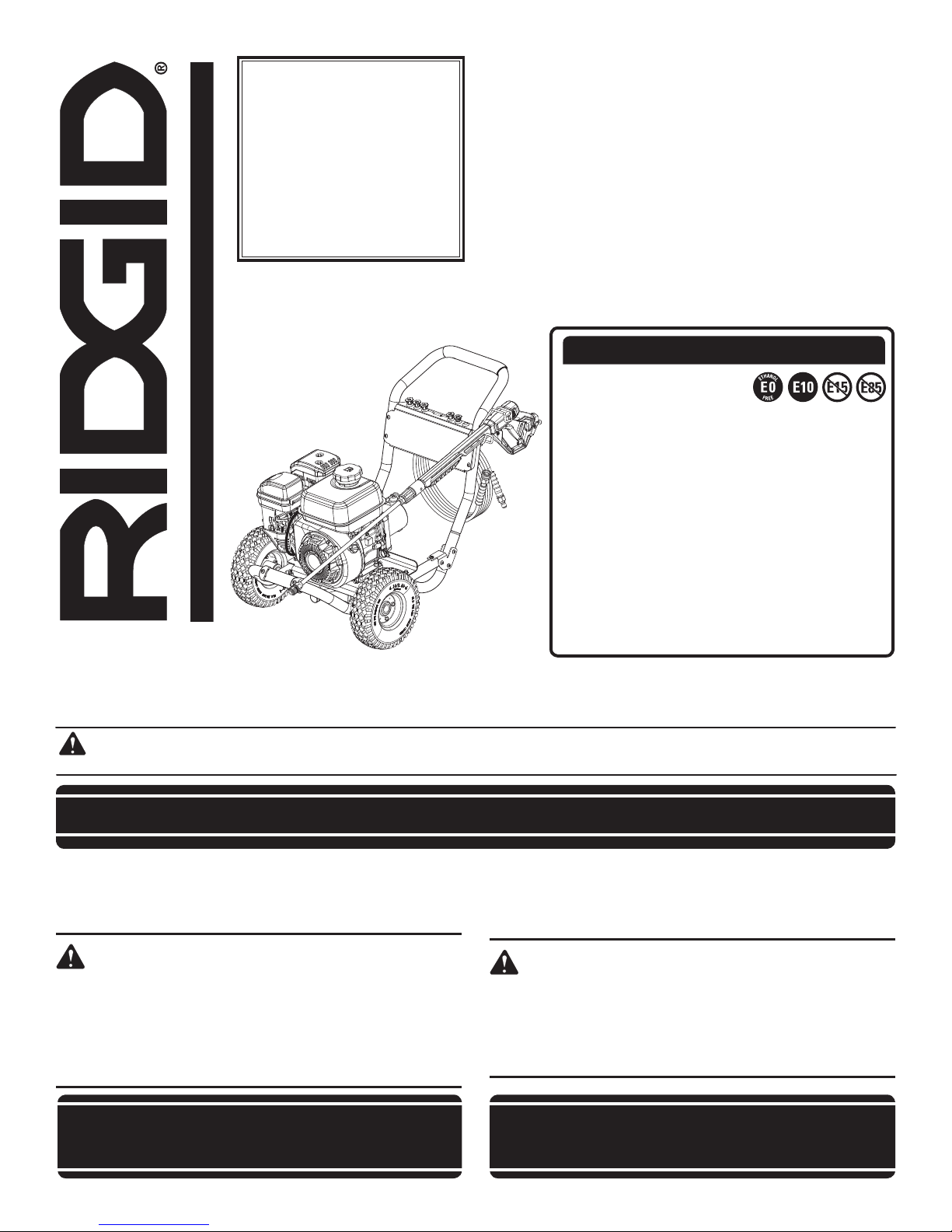
RIDGID RD80955 Operator's Manual
To register your RIDGID
product, please visit:
http://register.RIDGID.com
Pour enregistrer votre
produit de RIDGID, s’il
vous plaît la visite :
http://register.RIDGID.com
Para registrar su producto
de RIDGID, por favor visita:
http://register.RIDGID.com
OPERATOR’S MANUAL
MANUEL D’UTILISATION
MANUAL DEL OPERADOR
3000 PSI PRESSURE WASHER
NETTOYEUR HAUTE PRESSION
DE 3 000 PSI
LAVADORA A PRESIÓN DE 3 000 PSI
RD80955
NOTICE AVIS AVISO
Do not use E15 or E85 fuel
in this product. Only use unleaded gasoline containing
up to 10% ethanol. It is a violation of federal law
and will damage the unit and void your warranty.
Ne pas utiliser d’essence E15 ou E85 dans ce
produit. Utiliser seulement de l’essence sans
plomb ne contenant pas plus de 10 % d’éthanol.
Une telle utilisation représente une violation de la
loi fédérale et endommagera l’appareil et annulera
la garantie.
No utilice combustibles E15 o E85 con este
producto. Utilice únicamente gasolina sin plomo
que contiene hasta 10% de etanol. Esto constituye
una violación a la ley federal, dañará la unidad y
anulará la garantía.
Your pressure washer has been engineered and manufactured to our high standard for dependability, ease of operation, and
operator safety. When properly cared for, it will give you years of rugged, trouble-free performance.
WARNING: To reduce the risk of injury, the user must read and understand the operator’s manual before using this
product. If you do not understand the warnings and instructions in the operator’s manual, do not use this product.
SAVE THIS MANUAL FOR FUTURE REFERENCE
Ce nettoyeur haute pression à essence a été conçu et fabriqué
conformément à nos strictes normes de fiabilité, simplicité d’emploi
et sécurité d’utilisation. Correctement entretenu, cet outil vous
donnera des années de fonctionnement robuste et sans problème.
AVERTISSEMENT :
Pour réduire les risques de blessures, l’utilisateur doit
lire et veiller à bien comprendre le manuel d’utilisation
avant d’employer ce produit. Si tous les avertissements
et toutes les consignes de sécurités et instructions du
manuel d’utilisation ne sont pas bien compris, ne pas
utiliser ce produit.
CONSERVER CE MANUEL POUR
FUTURE RÉFÉRENCE
Su lavadora de presión de gasolina ha sido diseñado y fabricado de
conformidad con nuestras estrictas normas para brindar fiabilidad,
facilidad de uso y seguridad para el operador. Con el debido cuidado,
le brindará muchos años de sólido funcionamiento y sin problemas.
ADVERTENCIA:
Para reducir el riesgo de lesiones, el usuario debe leer y
comprender el manual del operador antes de usar este
producto. Guarde este manual del operador y estúdielo
frecuentemente para lograr un funcionamiento seguro y
continuo de este producto
GUARDE ESTE MANUAL PARA
FUTURAS CONSULTAS
See this fold-out section for all of the figures
referenced in the operator’s manual.
Consulter l’encart à volets afin d’examiner toutes les figures
mentionnées dans le manuel d’utilisation.
Consulte esta sección desplegable para ver todas las figuras
a las que se hace referencia en el manual del operador.
Fig. 1
J
A
C
B
A - Fuel cap (bouchon de carburant, tapa del
combustible)
B - Starter grip and rope (poignée du lanceur et
corde, mango del arrancador y cuerda)
C - Fuel tank (réservoir de carburant, tanque de
combustible)
D - Oil cap/dipstick (bouchon/jauge d’huile, tapa
del aceite con varilla de nivel)
E - Injection hose with filter (flexible d’injection
avec filtre, manguera de inyección con filtro)
K
L
H
N
D
F
F - Engine switch (commutateur de moteur,
interruptor del motor)
G - Choke (volet de départ, anegador)
H - High pressure hose (tuyau haute pression,
manguera de alta presión)
I - Nozzles and nozzle storage (buses et
etrangement de buse, boquillas y
compartimientos para boquillas)
J - Handle (poignée, mango)
E
I
M
G
O
K - Trigger handle (poignée de gâchete, mango
del gatillo)
L- Trigger with lock out (gâchette avec
verouillage, gatillo con seguro)
M- Spray wand (lance de pulvérisation, tubo de
rociado)
N- Muffler (silencieux, silenciador)
O- Fuel valve (robinet de carburant, válvula de
combustible)
Fig. 2
C
D
A - Hitch pin (axe de blocage, pasador de
enganche)
B - Washer (rondelle, arandela)
C - Wheel (roue, rueda)
D - Axle (essieu, eje)
A
B
Fig. 3
A
B
B
C
C
A - Handle (poignèe, mango)
B - Push to insert (capuchon de verrouillage du
manche, tapa de aseguramiento del mango)
C - Push-pin button (bouton-poussoir, para
chinches)
ii
Fig. 4
A
B
A - Trigger handle holder (support poignée de
gâchete, soporte para mango del gatillo)
B - Screw (boulon, perno)
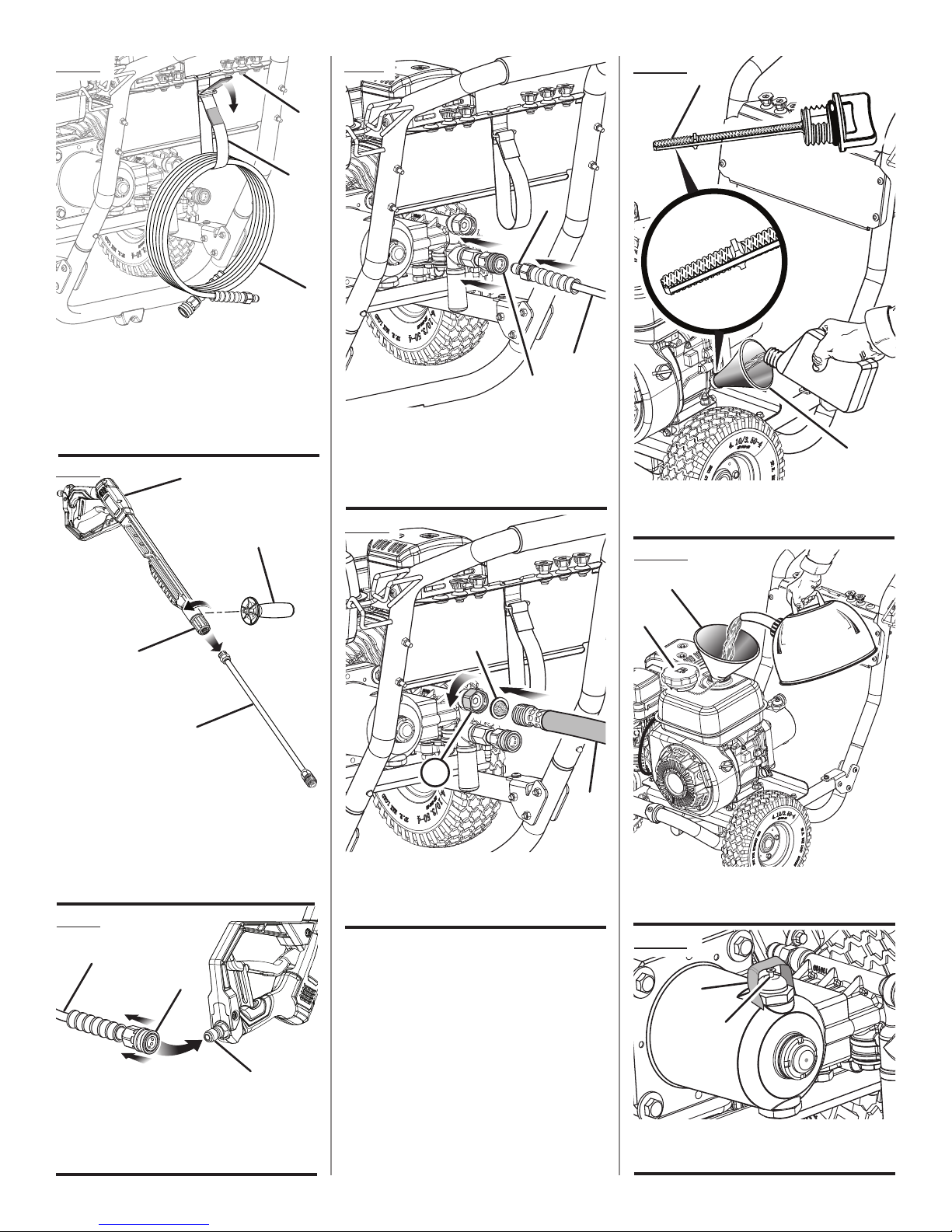
Fig. 5
A
B
A - Nozzle storage panel (panneau etrangement
de buse, panel compartimientos de la
boquilla)
B - Hook and loop strap (courroie de rangement,
correa de gancho y lazada)
C - High pressure hose (tuyau haute pression,
manguera para alta presión)
Fig. 6
A
B
Fig.8
C
A - Inlet coupler (raccord d’entrée, acoplador
de entrada)
B - Collar (collier, collarín)
C - High pressure hose (tuyau haute pression,
manguera de alta presión)
Fig. 9
Fig. 10
A
A
C
B
B
A - Oil cap/dipstick (bouchon / jauge d’huile,
tapa del aceite con varilla de nivel)
B - Funnel (entonnoir, embudo)
Fig. 11
A
C
D
A - Trigger handle (poignée de gâchette, mango
del gatillo)
B - Auxiliary handle (poignée auxiliaire, mango
auxiliar)
C - Connector (connecteur, conector)
D - Spray wand (lance de pulvérisation, tubo
rociador)
Fig. 7
C
B
B
A
C
A - Water intake (rise d’eau, entrada de agua)
B - Screen (tamis, cedazo)
C - Garden hose (tuyau d’arrosage, manguera
de jardín)
B
A - Funnel (entonnoir, embudo)
B - Fuel cap (bouchon du réservoir, tapa del
tanque de combustible)
Fig. 12
B
A
A
A - Inlet coupler (raccord d’entrée, acoplador
de entrada)
B - Collar (collier, collarín)
C - High pressure hose (tuyau haute pression,
manguera de alta presión)
A - Black plug (bouchon noir, tapón negro)
B - Caution label (autocollant de mise en garde,
etiqueta de precaución)
iii
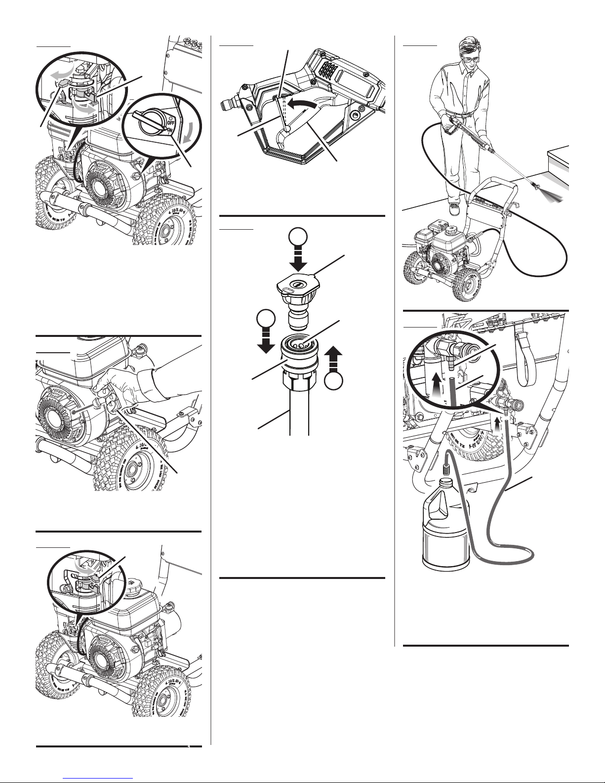
Fig. 13
Fig. 16
A
Fig. 18
B
C
A
A - Engine switch (ON) [commutateur de
moteur (MARCHE), interruptor del motor
(ENCENDIDO)]
B - Fuel valve (OPEN) [robinet de carburant
(OUVERT), válvula de combustible
(ABIERTO)]
C - Choke (START) [volet de départ
(DÉMARRAGE), anegador (ARRANQUE)]
Fig. 14
B
A - Slot (encoche, ranura)
B - Lock out (verrouillage, seguro)
C - Trigger (gâchette, gatillo)
Fig. 17
F
25
E
C
G
C
A
B
Fig. 19
A
B
A
A - Starter grip and rope (poignée du lanceur
avec corde, mango del arrancador con
cuerda)
Fig. 15
A
D
A - Nozzle (buse, boquilla)
B - “Click” (déclic, hasta que trabe)
C - Quick-connect collar (casquillo de conexión
rápida)
D - Spray wand (lance de pulvérisation, tubo de
rociador)
E - Pull back the quick-connect collar (tirer la
bague à connexion rapide, tire del collar de
conexión rápida)
F - Push the nozzle into place (insérer en place la
buse, introduzca la boquilla en su lugar)
G - Push the collar forward (poussez en avant la
bague, empuje del collar adelante)
B
C
A - Injection hose fitting (raccord du flexible
d’injection, adaptador de la manguera de
inyección)
B - Injection hose with filter (flexible d’injection
avec filtre, manguera de inyección con filtro)
C - Detergent (détergent, detergente)
A - Choke (RUN) [volet de départ (MARCHE),
anegador (FUNCIONAMIENTO)]
iv
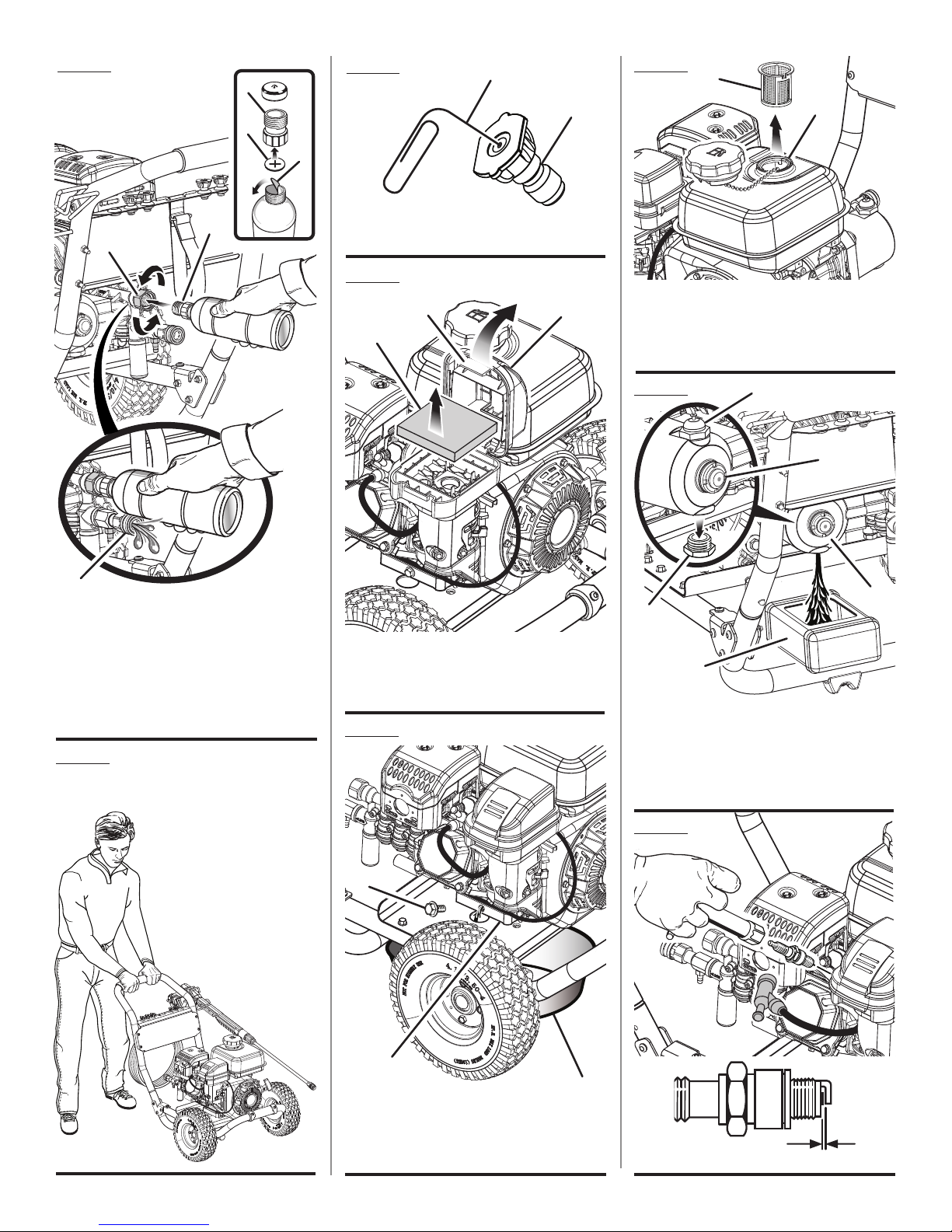
Fig. 20
Fig. 22
A
A
B
Fig. 25
A
B
B
C
A
D
E
A - Threaded top (bouchon vissé, parte superior
roscada)
B - Rubber seal (joint de caoutchouc, sello de
goma)
C - Paper seal (sceaux de papier, sello de papel)
D - Water intake (rise d’eau, entrada de agua)
E - Pump outlet (sortie de la pompe, orificio de
descarga de la bomba)
Fig. 21
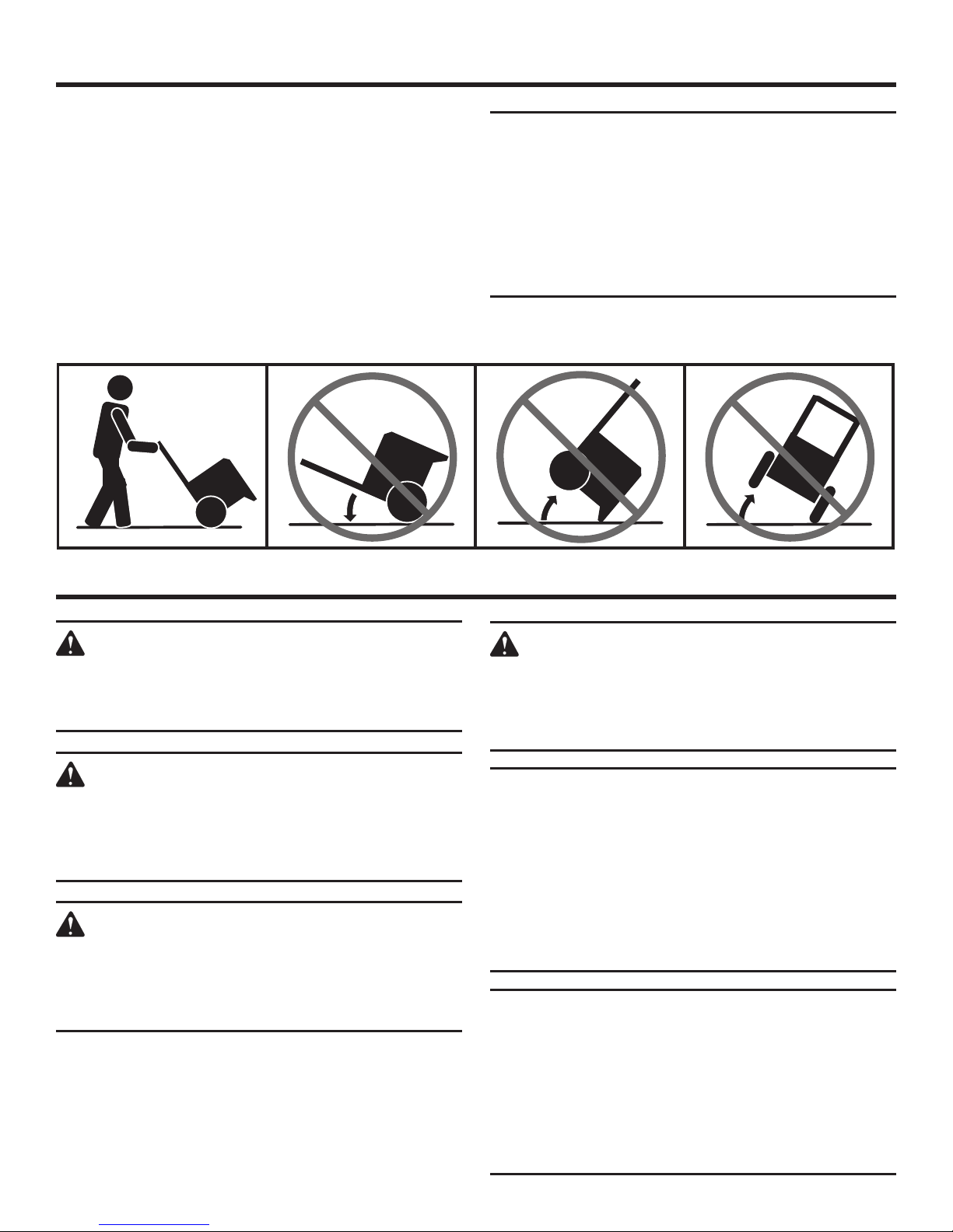
TO MOVE THE MACHINE
DÉPLACEMENT DE LA
MACHINE
PARA MOVER LA
MÁQUINA
A - Paper clip (pièces de papier, clips de papel)
B - Nozzle (buse, boquilla)
Fig. 23
B
C
A - Filter cover (couvercle du filtre à air, tapa de
la cámara de ventilación)
B - Tab (languette, orejeta)
C - Foam filter (filtre, filtro)
A
Fig. 24
A - Fuel tank inlet screen (grillage d’admission
du réservoir de carburant, filtro de entrada
del tanque de combustible)
B - Tank filler neck (goulot de remplissage du
réservoir, boca del depósito)
Fig. 26
D
A
E
B
C
A - Sight glass (voyant d’huile, visor)
B - Oil drain plug (bouchon huile, tapón de
drenaje del aceite)
C - Container (conteneur, recipiente)
D - Pump oil cap (bouchon du réservoir d’huile
de la pompe, tapa de aceite de la bomba)
E - Pump (pompe, bomba)
Fig. 27
A
C
B
A - Oil drain plug (bouchon de vidange d’huile,
tapón de drenaje del aceite)
B - Container (conteneur, recipiente)
C - Engine (moteur, motor)
v
A
A - 0.7 - 0.8 mm (0,7 - 0,8 mm)

TABLE OF CONTENTS
TABLE DES MATIÈRES / ÍNDICE DE CONTENIDO
Introduction ......................................................................................................................................................................2
Introduction / Introducción
Important Safety Instructions ........................................................................................................................................... 3
Instructions importantes concernant la sécurité / Instrucciones de seguridad importantes
Specific Safety Rules ........................................................................................................................................................ 4
Règles de sécurité particulières / Reglas de seguridad específicas
Symbols .........................................................................................................................................................................5-6
Symboles / Símbolos
Features ............................................................................................................................................................................7
Caractéristiques / Características
Assembly .....................................................................................................................................................................8-10
Assemblage / Armado
Operation ...................................................................................................................................................................10-15
Utilisation / Funcionamiento
Maintenance ..............................................................................................................................................................16-19
Entretien / Mantenimiento
Troubleshooting .............................................................................................................................................................. 20
Dépannage / Solución de problemas
Warranty ....................................................................................................................................................................21-22
Garantie / Garantía
Parts Ordering and Service ...............................................................................................................................Back page
Commande de pièces et réparation / Pedidos de piezas y servicio ................................................................páge arrière / pág. posterior
INTRODUCTION
INTRODUCTION / INTRODUCCIÓN
This product has many features for making its use more pleasant and enjoyable. Safety, performance, and dependability
have been given top priority in the design of this product making it easy to maintain and operate.
* * *
Ce produit offre de nombreuses fonctions destinées à rendre son utilisation plus plaisante et satisfaisante. Lors de la
conception de ce produit, l’accent a été mis sur la sécurité, les performances et la fiabilité, afin d’en faire un outil facile à
utiliser et à entretenir.
* * *
Este producto ofrece numerosas características para hacer más agradable y placentero su uso. En el diseño de este producto
se ha conferido prioridad a la seguridad, el desempeño y la fiabilidad, por lo cual se facilita su manejo y mantenimiento.
2

IMPORTANT SAFETY INSTRUCTIONS
DANGER:
Risk of fire and serious burns: Never remove fuel
cap when unit is running. Shut off engine and allow the
unit to cool at least five minutes. Remove cap slowly.
WARNING:
Read and understand all instructions. Failure to
follow all instructions listed below may result in electric
shock, fire and/or carbon monoxide poisoning which
will cause death or serious personal injury.
READ ALL INSTRUCTIONS
Know your tool. Read the operator’s manual carefully.
Learn the machine’s applications and limitations as well
as the specific potential hazards related to this tool.
Keep guards in place and in working order. Never
operate the tool with any guard or cover removed. Make
sure all guards are operating properly before each use.
Remove adjusting keys and wrenches. Form habit of
checking to see that keys and adjusting wrenches are
removed from tool before turning it on.
To reduce the risk of injury, keep children and visitors
away. All visitors should wear safety glasses and be kept
a safe distance from work area.
Keep the area of operation clear of all persons,
particularly small children, and pets.
Do not start or operate the engine in a confined space,
building, near open windows, or in other unventilated
space where dangerous carbon monoxide fumes can
collect. Carbon monoxide, a colorless, odorless, and
extremely dangerous gas, can cause unconsciousness
or death.
Use right tool. Don’t force tool or attachment to do a job it
was not designed for. Don’t use it for a purpose not intended.
Dress properly. Wear long pants and long sleeves. Do
not wear loose clothing, gloves, neckties, or jewelry. They
can get caught and draw you into moving parts. Rubber
gloves and nonskid footwear are recommended when
working outdoors. Also wear protective hair covering to
contain long hair.
Do not operate the equipment while barefoot or when
wearing sandals or similar lightweight footwear. Wear
protective footwear that will protect your feet and improve
your footing on slippery surfaces.
Exercise caution to avoid slipping or falling.
Always wear eye protection with side shields marked
to comply with ANSI Z87.1. Following this rule will
reduce the risk of serious personal injury.
Don’t overreach or stand on ladder, rooftop or other
Use only recommended accessories. The use of
Follow the maintenance instructions specified in this
Check damaged parts. Before further use of the
Never leave tool running unattended. Turn power off.
Keep the engine free of grass, leaves, or grease to
Keep the exhaust pipe free of foreign objects.
Follow manufacturer’s recommendations for
Be thoroughly familiar with controls. Know how to stop
Keep tool dry, clean, and free from oil and grease.
Stay alert and exercise control. Watch what you are
Do not operate the product while under the influence
Check the work area before each use. Remove all
Do not use tool if switch does not turn it off. Have
Before cleaning, repairing, or inspecting, shut off the
Avoid dangerous environment. Don’t use in damp or
Never use in an explosive atmosphere. Normal
Do not operate while smoking or near an open flame.
Do not operate around dry brush, twigs, cloth rags, or
WARNING: Risk of injection or injury – Do not direct
3 - English
unstable support. Keep proper footing and balance at
all times.
improper accessories may cause risk of injury.
manual.
tool, a
guard or other part that is damaged should be carefully
checked to determine that it will operate properly and
perform its intended function. Check for alignment of
moving parts, binding of moving parts, breakage of parts,
mounting, and any other conditions that may affect its
operation. A guard or other part that is damaged must
be properly repaired or replaced by a qualified service
center to avoid risk of personal injury.
Don’t leave tool until it comes to a complete stop.
reduce the chance of a fire hazard.
safeloading, unloading, transport, and storage of
machine.
the product and bleed pressure quickly.
Always use a clean cloth when cleaning. Never use
brake fluids, gasoline, petroleum-based products, or any
solvents to clean tool.
doing and use common sense. Do not operate tool when
you are tired. Do not rush.
of drugs, alcohol, or any medication.
objects such as rocks, broken glass, nails, wire, or string
which can be thrown or become entangled in the machine.
defective switches replaced by a qualified service center.
engine and make certain all moving parts have stopped.
Disconnect the spark plug wire, and keep the wire away
from the plug to prevent accidental starting.
wet locations or expose to rain. Keep work area well lit.
sparking of the motor could ignite fumes.
other flammable materials.
discharge stream at persons.

SPECIFIC SAFETY RULES
Use caution when positioning the pressure washer
for use. Warm air from the engine could cause discol-
ored spots on grass.
Never direct a water stream toward people or pets,
or any electrical device.
Before starting any cleaning operation, close doors
and windows. Clear the area to be cleaned of debris,
toys, outdoor furniture, or other objects that could create
a hazard.
Never pick up or carry a machine while the engine is
running.
Never start the machine if ice has formed in any part
of the equipment.
Do not use acids, alkalines, solvents, flammable
material, bleaches, or industrial grade solutions
in this product. These products can cause physical
injuries to the operator and irreversible damage to the
machine.
Always operate the machine on a level surface. If the
engine is on an incline, it could seize due to improper
lubrication (even at the maximum lubricant level).
WARNING: High pressure jets can be dangerous if
subject to misuse. The jet must not be directed at
persons, animals, electrical devices, or the machine
itself.
Hold the trigger handle securely with both hands.
Expect the trigger handle to move when the trigger is
pulled due to reaction forces. Failure to do so could cause
loss of control and injury to yourself and others.
Never attempt to make any adjustments while the
engine (motor) is running (except where specifically
recommended by the manufacturer).
Protective covers must always cover rotating parts
when the engine is running.
Keep cooling air intake (starter grip and rope area)
and muffler side of the engine at least 3 feet away from
buildings, obstructions, and other combustible objects.
Keep the engine away from flammables and other
hazardous materials.
Keep away from hot parts. The muffler and other engine
parts become very hot; use caution.
Do not touch the spark plug and ignition cable when
starting and operating the engine.
Check fuel hoses and joints for looseness and fuel
leakage before each use.
Check bolts and nuts for looseness before each use.
A loose bolt or nut may cause serious engine problems.
Always refuel outdoors. Never refuel indoors or in a
poorly ventilated area.
Never store the machine with fuel in the fuel tank
inside a building where ignition sources are present, such
as hot water and space heaters, clothes dryers, and the
like.
If the fuel tank has to be drained, do this outdoors into
a container approved for gasoline and away from all
ignition sources.
To reduce the risk of fire and burn injury, handle fuel
with care. It is highly flammable.
Do not smoke while handling fuel.
Add fuel before starting the engine. Never remove the
cap of the fuel tank or add fuel while the engine is running
or when the engine is hot.
Loosen fuel cap slowly to release pressure and to keep
fuel from escaping around the cap.
Replace all fuel tank and container caps securely.
Wipe spilled fuel from the unit. Move 30 feet away from
refueling site before starting engine.
If fuel is spilled, do not attempt to start the engine but
move the machine away from the area of spillage and
avoid creating any source of ignition until fuel vapors
have dissipated.
Never attempt to burn off spilled fuel under any
circumstances.
Before storing, allow the engine to cool and drain fuel
from the unit.
Store fuel in a cool, well-ventilated area, safely away
from spark and/or flame-producing equipment.
Store fuel in containers specifically designed for this
purpose.
Empty fuel tank and restrain the unit from moving
before transporting in a vehicle.
When servicing use only recommended or equivalent
replacement parts. Use of any other parts may create a
hazard or cause product damage.
ONLY use cold water.
Make sure minimum clearance of 3 feet is maintained
from combustible materials.
Never spray close to the surface to be cleaned as you
can damage the surface.
After stopping the engine, always pull the trigger on
the trigger handle to relieve stored pressure in the high
pressure hose. Failure to do so could result in serious
personal injury.
Ensure the high pressure hose is properly connected
before using the product.
For outdoor use only.
Save these instructions. Refer to them frequently and
use them to instruct other users. If you loan someone this
tool, loan them these instructions also.
4 - English
SYMBOLS
The following signal words and meanings are intended to explain the levels of risk associated with this product.
SYMBOL SIGNAL MEANING
DANGER:
WARNING:
CAUTION:
NOTICE:
Some of the following symbols may be used on this product. Please study them and learn their meaning for safe
operation of this product.
SYMBOL NAME EXPLANATION
Safety Alert Indicates a potential personal injury hazard.
Read Operator’s Manual
Indicates an imminently hazardous situation, which, if not avoided, will result
in death or serious injury.
Indicates a potentially hazardous situation, which, if not avoided, could result
in death or serious injury.
Indicates a potentially hazardous situation, which, if not avoided, may result in
minor or moderate injury.
(Without Safety Alert Symbol) Indicates important information not related to an
injury hazard, such as a situation that may result in property damage.
To reduce the risk of injury, user must read and understand
operator’s manual before using this product.
Eye Protection
Wet Conditions Alert Do not expose to rain or use in damp locations.
Hot Surface
Risk of Injections
Risk of Explosion
Risk of Fire
Always wear eye protection with side shields marked to comply
with ANSI Z87.1.
To reduce the risk of injury or damage, avoid contact with any
hot surface.
To reduce the risk of injection or injury, never direct a water
stream towards people or pets or place any body part in the
stream. Leaking hoses and fittings are also capable of causing
injection injury. Do not hold hoses or fittings.
Do not spray flammable liquids. Flammable liquids, fuel, and
their vapors are explosive and can cause severe burns or death.
Fuel and its vapors are extremely flammable and explosive. Fire
can cause severe burns or death.
5 - English
SYMBOLS
Some of the following symbols may be used on this product. Please study them and learn their meaning for safe
operation of this product.
SYMBOL NAME EXPLANATION
Gas products emit carbon monoxide, an odorless, colorless,
Toxic Fumes
poison gas. Breathing carbon monoxide can cause nausea,
fainting, or death.
Kickback
Electric Shock
Chemical Burns
To reduce the risk of injury from kickback, hold the spray wand
securely with both hands when the machine is on.
Failure to use in dry conditions and to observe safe practices
can result in electric shock.
To reduce the risk of injury or damage, DO NOT USE ACIDS,
ALKALINES, BLEACHES, SOLVENTS, FLAMMABLE MATERIAL,
OR INDUSTRIAL GRADE SOLUTIONS in this product.
CALIFORNIA PROPOSITION 65
WARNING:
This product, its exhaust, and other substances that may become airborne from its use may contain chemicals,
including lead, known to the State of California to cause cancer, birth defects, or other reproductive harm. Wash
hands after handling.
6 - English

FEATURES
PRODUCT SPECIFICATIONS
Lubricant Fill Volume .............................................................................................................................Approximately 17 oz.
Spark Plug .................................................................................................................................Torch/LG F6TC or equivalent
Fuel Tank Capacity ..................................................................................................................................................... 0.98 gal
Maximum Pounds Per Square Inch Pressure* .........................................................................................................3,000 psi
Maximum Gallons Per Minute* ...................................................................................................................................2.6 gpm
Maximum Inlet Water Temperature ................................................................................................................................104˚F
*Max. rating determined by PWMA Standard 101, when tested with red nozzle
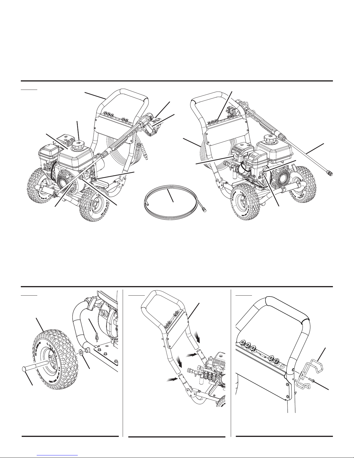
KNOW YOUR PRESSURE WASHER
See Figure 1.
The safe use of this product requires an understanding of
the information on the tool and in this operator’s manual as
well as a knowledge of the project you are attempting. Before
use of this product, familiarize yourself with all operating
features and safety rules.
ENGINE SWITCH
The engine switch is used in combination with the starter
grip and rope to start the engine. It is also used to turn the
engine off.
FUEL TANK
This fuel tank has a maximum capacity of 0.98 gal. (3.7 liters).
Use unleaded automotive gasoline in the engine.
HOSE STORAGE
Once the high pressure hose is rolled, hang it on the back of
the machine using the hook and loop strap to secure in place.
IDLE DOWN
The engine idle speed is automatically reduced when the
trigger is released. This feature increases fuel efficiency,
reduces the noise level, and decreases wear and tear over
the life of the pressure washer.
SOAP NOZZLE
The blue soap nozzle is used to apply detergent at low
pressure only.
STARTER GRIP AND ROPE
The starter grip and rope is pulled to start the machine.
THERMAL RELIEF VALVE
This pump feature will prevent water temperatures from
reaching harmful levels by releasing a small amount of
water. Once the water has drained, the thermal relief valve
will reset itself.
TRIGGER HANDLE
The trigger handle has a gripping surface that provides
added control of the spray wand and helps reduce fatigue.
TRIGGER WITH LOCK OUT
Pulling the trigger releases a stream of water for high
pressure cleaning. The lock out provides protection against
unauthorized use.
7 - English
ASSEMBLY
UNPACKING
This product requires assembly.
Carefully cut the box down the sides then remove the
product and any accessories from the box. Make sure
that all items listed in the packing list are included.
NOTE: This product is heavy. To avoid back injury, lift with
your legs, not your back, and get help when needed.
WARNING:
If any parts are damaged or missing do not operate
this product until the parts are replaced. Use of this
product with damaged or missing parts could result
in serious personal injury.
WARNING:
Do not use this product if any parts on the Packing
List are already assembled to your product when
you unpack it. Parts on this list are not assembled
to the product by the manufacturer and require
customer installation. Use of a product that may
have been improperly assembled could result in
serious personal injury.
Inspect the product carefully to make sure no breakage
or damage occurred during shipping.
Do not discard the packing material until you have care-
fully inspected and satisfactorily operated the product.
If any parts are damaged or missing, please call
1-866-539-1710 for assistance.
PACKING LIST
Pressure Washer
30 ft. High Pressure Hose
Auxiliary handle
Trigger Handle
Spray Wand
Quick-connect Nozzles (5)
Injection Hose with Injection Hose Filter
4-Cycle Engine Lubricant (SAE 30 or SAE 10W30)
Handle
Trigger Handle Holder
Screw
Axle (2)
Hitch pins (2)
Wheels (2)
Washers (2)
Hook-and-Loop Strap
Disposable Funnel
Operator’s Manual
WARNING:
Do not attempt to modify this product or create
accessories not recommended for use with this
tool. Any such alteration or modification is misuse
and could result in a hazardous condition leading
to possible serious personal injury.
WARNING:
To prevent accidental starting that could cause
serious personal injury, always disconnect the
engine spark plug wire from the spark plug when
assembling parts.
INSTALLING THE WHEELS
See Figure 2.
Locate the axles, hitch pins, washers, and wheels.
Slide the axle through the hole in the center of the wheel.
Slide the washer onto the axle.
Lift the machine and slide the axle into the wheel mount-
ing hole in the machine base as shown.
Push the hitch pin into the hole on the end of the axle to
secure the wheel assembly.
NOTE: The hitch pin should be pushed into the axle until
the center of the pin rests on top of the axle.
Repeat with the second wheel.
INSTALLING THE HANDLE
See Figure 3.
CAUTION:
Be careful to avoid pinching your fingers or hands
when installing the handle onto the frame.
8 - English

ASSEMBLY
To install the handle:
Push and hold the push-pin buttons on the frame as you
slide the handle onto the frame and over the buttons.
Adjust the handle so that the frame push-pin buttons
snap into holes in the base of the handle.
NOTE: Before use, pull the handle up until the push-pin
buttons snap through the locking holes to secure the
handle in place.
INSTALLING TRIGGER HANDLE HOLDER
See Figure 4.
Insert trigger handle holder into hole in handle, as shown.
Thread screw through holder and into handle. Tighten
securely.
ATTACHING HOOK-AND-LOOP HOSE
STORAGE STRAP
See Figure 5.
Locate the slot in the top of the nozzle storage panel.
Slide hook and loop strap into slot and buckle.
Neatly coil the high pressure hose and store with hook
and loop strap.
CONNECTING THE SPRAY WAND TO THE
TRIGGER HANDLE
See Figure 6.
Place the threaded end of the spray wand in the connec-
tor on the end of the trigger handle.
Turn the connector clockwise until it stops. This secures
the wand in place.
ATTACHING THE AUXILIARY HANDLE
See Figure 6.
Place the threaded stud on the end of the auxiliary handle
into the hole in the trigger handle as shown. Turn clockwise to tighten.
NOTE: You can install the handle on either the left or right
side of the spray wand, depending on operator preference.
To switch sides, loosen the auxiliary handle and rotate to
the opposite side. Tighten securely before use.
CONNECTING HIGH PRESSURE HOSE TO
TRIGGER HANDLE
See Figure 7.
Pull back and hold the collar on the high pressure hose.
Insert the inlet coupler on the trigger handle into the collar.
Release the collar and push until it locks into place. Pull
on the hose to be certain it is properly secured.
CONNECTING THE HIGH PRESSURE HOSE TO
THE PUMP
See Figure 8.
Completely uncoil and straighten the high pressure hose
to prevent kinks.
NOTE: See Using The High Pressure Hose in Operation
for more information about using the high pressure hose.
Pull back and hold the collar on the pump outlet. Insert
the inlet coupler on the high pressure hose into the collar.
Release the collar and push until it locks into place. Pull
on the hose to be certain it is properly secured.
CONNECTING THE GARDEN HOSE TO THE
PRESSURE WASHER
See Figure 9.
NOTICE:
Always observe all local regulations when connecting hoses to the water main. Some areas have
restrictions against connecting directly to public
drinking water supply to prevent the feedback of
chemicals into the drinking water supply. Direct
connection through a receiver tank or backflow
preventer is usually permitted.
The water supply must come from a water main. NEVER use
hot water or water from pools, lakes, etc. Before connecting
the garden hose to the pressure washer:
Run water through the hose for 30 seconds to clean any
debris from the hose.
Inspect the screen in the water intake.
If the screen is damaged, do not use the machine until
the screen has been replaced.
If the screen is dirty, clean it before connecting the garden
hose to the machine.
9 - English
ASSEMBLY
To connect the garden hose to the machine:
Completely uncoil the garden hose or remove completely
from reel to prevent kinks.
NOTE: There must be a minimum of 10 feet of unrestricted
hose between the pressure washer intake and the hose
faucet or shut off valve (such as a “Y” shut off connector).
With the hose faucet turned completely off, attach the
end of the garden hose to the water intake. Tighten by
hand.
DO NOT OVERTILT THE UNIT!
NOTICE:
Do not run the pressure washer without water supply connected and turned on, as this may damage
the high pressure seals and decrease pump life.
Completely unwind the hose from its reel or coil
and make sure the hose is not being restricted by
tires, rocks, or any other objects that may lessen or
prevent water flow to the pressure washer.
OPERATION
WARNING:
Do not allow familiarity with this product to make
you careless. Remember that a careless fraction of
a second is sufficient to inflict serious injury.
WARNING:
Always wear eye protection with side shields
marked to comply with ANSI Z87.1. Failure to do
so could result in objects being thrown into your
eyes, resulting in possible serious injury.
WARNING:
Do not use any attachments or accessories not
recommended by the manufacturer of this product.
The use of attachments or accessories not recommended can result in serious personal injury.
WARNING:
Never direct a water stream toward people or pets,
or any electrical device. Failure to follow these
instructions could result in serious injury, electric
shock, or death.
NOTICE:
The spark arrestor on this product has not been
evaluated by the USDA Forest Service and cannot
be used on U.S. forest lands. In addition, product
users must comply with Federal, State, and local
fire prevention regulations. Check with appropriate
authorities. Contact customer service or a qualified
service center to purchase a replacement spark
arrestor.
NOTICE:
Before each use, inspect the entire product for
damaged, missing, or loose parts such as screws,
nuts, bolts, caps, etc. Tighten securely all fasteners and caps and do not operate this product until
all missing or damaged parts are replaced. Please
contact customer service or a qualified service
center for assistance.
10 - English

OPERATION
APPLICATIONS
You may use this tool around the house for cleaning most
small to large horizontal or vertical exterior surfaces, smaller
exterior objects and structures, and outdoor equipment and
tools.* You can:
Clean or remove mold and mildew from weathered decks,
driveways, patios, walkways, sidewalks, etc.
Remove dirt from various exterior vertical surfaces such
as house exteriors, siding, fences, brick, concrete or stone
walls, etc.
Wash boats, outdoor furniture, powered or non-powered
garden equipment, gutters, window screens, grills, playground equipment, etc.
*Always test in an inconspicuous area first.
ADDING/CHECKING ENGINE LUBRICANT
See Figure 10.
NOTE: This machine has been shipped with approximately
2 oz. of lubricant in the engine from testing. You must add
lubricant to the engine before starting it the first time.
NOTICE:
Any attempt to start the engine without adding
lubricant will result in engine failure.
To add engine lubricant:
Place pressure washer on a flat, level surface. Do not tilt.
Unscrew the oil cap/dipstick by turning counter-
clockwise.
Before first use, squeeze the entire contents of the
lubricant container provided into the oil reservoir.
After initial use, add 4-stroke engine lubricant (SAE 30 or
SAE 10W30) until the fluid level rises to the upper portion
of the hatched area on the dipstick. Do not overfill.
Replace the oil cap / dipstick and securely tighten.
To check engine lubricant level:
Place pressure washer on a flat, level surface. Do not tilt.
Unscrew the oil cap/dipstick by turning counter-
clockwise.
Wipe dipstick clean and re-seat in hole; do not rethread.
Remove dipstick again and check lubricant level. Lubricant
level should fall within the hatched area on the dipstick.
If level is low, add engine lubricant until the fluid level rises
to the upper portion of the hatched area on the dipstick.
Replace and secure the oil cap/dipstick.
OXYGENATED FUELS
NOTICE:
Do not use E15 or E85 fuel in this product. Only
use unleaded gasoline containing up to 10%
ethanol. It is a violation of federal law and will
damage the unit and void your warranty.
Fuel system damage or performance problems resulting
from the use of an oxygenated fuel containing more than
the percentage of oxygenates stated below are not covered
under warranty.
ADDING GASOLINE TO THE FUEL TANK
See Figure 11.
DANGER:
Risk of fire and serious burns: Never remove fuel
cap when unit is running. Shut off engine and allow the unit to cool at least five minutes. Remove
cap slowly.
WARNING:
Gasoline and its vapors are highly flammable and
explosive. To prevent serious personal injury and
property damage, handle gasoline with care. Keep
away from ignition sources, handle outdoors only,
do not smoke while adding fuel, and wipe up spills
immediately.
WARNING:
Always shut off engine before fueling. Never remove
fuel cap or add fuel to a machine with a running
or hot engine. When adding gas to the pressure
washer, make sure the unit is sitting on a flat, level
surface and only add fuel outdoors. If the engine
is hot, let the pressure washer cool for at least five
minutes before adding gas. Immediately replace
fuel cap after fueling and tighten until the cap
“clicks.” Move at least 30 ft. from refueling site
before starting engine. Do not smoke and stay
away from open flames and sparks! Failure to follow
these instructions could result in a fire and cause
serious personal injury.
NOTICE:
Do not overfill. Overfilling the crankcase may cause
excessive smoke and engine damage.
NOTE: This is a 4-cycle engine. DO NOT mix fuel and
lubricant together.
Mix fuel stabilizer with gasoline according to fuel stabilizer
manufacturer’s directions.
11 - English
OPERATION
Before removing the fuel cap, clean the area around it.
Remove the fuel cap.
Insert a clean funnel into the fuel tank then slowly
pour gasoline into the tank. Fill tank to approximately
1-1/2 in. below the top of the tank neck (this allows for
fuel expansion).
Replace fuel cap and tighten until the cap “clicks”.
Clean up any spills before starting the engine.
STARTING AND STOPPING THE PRESSURE
WASHER
See Figures 12 - 15.
NOTICE:
Do not run the pressure washer without water supply connected and turned on, as this may damage
the high pressure seals and decrease pump life.
Completely unwind the hose from its reel or coil
and make sure the hose is not being restricted by
tires, rocks, or any other objects that may lessen or
prevent water flow to the pressure washer.
Before first time use:
Remove caution label and black plug from the red cap
on pump.
Before starting the engine:
Connect all hoses.
NOTE: Make sure the pressure washer’s water intake
screen is in place and unclogged before connecting
garden hose.
Check all fluids (lubricants and gas).
NOTE: The engine is equipped with a low oil sensor that
will prevent the engine from starting and/or running if
there is insufficient lubricant in the crankcase.
Turn on the garden hose then pull the trigger to relieve air
pressure; hold the trigger until a steady stream of water
appears.
NOTE: Make sure the faucet is turned on fully and that
there are no kinks or leaks in the hose.
To start the engine:
Place the engine switch in the ON ( l ) position.
Open the fuel valve.
Move the choke lever to the START position.
NOTE: If restarting after a brief stop (i.e., after refueling
or moving), leave the choke lever in the RUN position.
Pull the starter grip and rope until the engine runs (a
maximum of 6 times).
NOTE: Do not allow the grip to snap back after starting;
return it gently to its original place.
Pull the trigger to relieve air pressure; hold the trigger until
a steady stream of water appears.
WARNING:
If the engine does not start after each pull of the
starter grip and rope, squeeze the trigger to relieve
water pressure before attempting to start the engine again. Failure to relieve water pressure can
cause the starter grip and rope to lock up and result
in serious personal injury.
As the engine warms up, move the choke lever slowly to
the RUN position.
Let the engine warm up a few minutes before using.
NOTICE:
Routinely make a visual inspection of the pump
and engine during use. If you notice any lubricant
leaking around the pump or engine seals, stop
using the pressure washer immediately. Contact
customer service or a qualified service center for
repair. Failure to do so may cause property damage.
To stop the engine:
Turn the engine switch to OFF ( O ) position.
Close the fuel valve.
Pull trigger to release water pressure.
Disconnect all hoses.
WARNING:
While operating and storing, keep at least 3 feet
of clearance on all sides of this product, including overhead. Allow a minimum of 30 minutes of
“cool down” time before storage. Keep all body
parts, clothing, combustible materials, and hoses
away from the muffler. Heat created by muffler
and exhaust gases could be hot enough to cause
serious burns, ignite combustible objects, and/or
damage high pressure hoses that can result in an
injection injury.
12 - English
OPERATION
USING THE TRIGGER HANDLE
See Figure 16.
WARNING:
Hold the trigger handle securely with both hands.
Expect the trigger handle to move when the trigger
is pulled due to reaction forces. Failure to do so
could cause loss of control and injury to yourself
and others.
Pull back and hold the trigger to operate the pressure
washer.
Release the trigger to stop the flow of water through the
nozzle.
To engage the lock out:
Push up on the lock out until it clicks into the slot.
To disengage the lock out:
Push the lock out down and into its original position.
Start with the nozzle 1-2 ft. away from the cleaning surface
and carefully approach the surface just until the desired
level of cleaning is achieved. If the spray is too close it can
damage the cleaning surface.
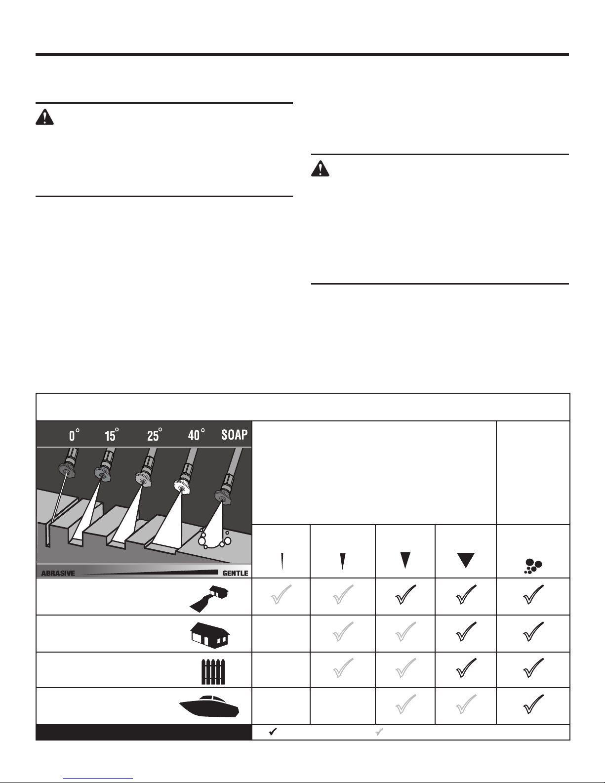
SELECTING THE RIGHT NOZZLE FOR THE JOB
See Figure 17.
Each of the nozzles has a different spray pattern. Before
starting any cleaning job, determine the best nozzle for the
job. Refer to the Nozzle Selection Guide, for more information about which nozzle to choose.
WARNING:
NEVER remove nozzles without first turning off the
engine, relieving the water pressure in the trigger
handle, and locking the lock out on the trigger
handle. NEVER point the nozzle at your face or at
others. The quick-connect feature contains small
springs that could eject the nozzle with some force.
Failure to follow these instructions could result in an
eye injury or other serious personal injury.
To connect a nozzle to the spray wand:
Turn off the pressure washer and shut off the water
supply. Pull trigger to release water pressure.
Engage the lock out on the trigger handle by pushing up
on the lock out until it clicks into the slot.
Pull back the quick-connect collar.
Concrete, Brick, Masonry
Siding, Gutters, House
Fencing, Deck, Patio
NOZZLE SELECTION GUIDE
HIGH PRESSURE
(NO SOAP WHEN USING THESE NOZZLES)
0º Red
15º
Yellow
25º Green 40º White
LOW
PRESSURE
(FOR SOAP OR
GENTLE RINSE)
Blue Soap
Nozzle
Lawn Equipment, Boat, RV
Recommended Nozzle Use With Caution for Certain Applications
13 - English

OPERATION
Push the nozzle into place in the spray wand.
Push the collar forward so that the nozzle is secured
properly. Check to see that the nozzle is secure.
To disconnect a nozzle from the spray wand once the
cleaning job is complete:
Turn off the pressure washer and shut off the water
supply. Pull trigger to release water pressure.
Engage the lock out on the trigger handle by pushing up
on the lock out until it clicks into the slot.
Pull back and hold the quick-connect collar.
Remove the nozzle by pulling it from the quick-connect
collar. Place nozzle in the nozzle storage area on the top
of the machine.
USING THE HIGH PRESSURE HOSE
See Figure 18.
WARNING:
Injection hazard. Fully unwrap and straighten high
pressure hose prior to and during each use and
do not allow it to become kinked. The high pressure hose features an outer covering that provides
strength to the hose. If the outer covering becomes
damaged, stop using the hose and replace it immediately. A kinked or damaged hose can develop a
high pressure leak and result in a possible injection
or other serious personal injury.
To prevent damage to the outer covering:
Inspect the hose before every use.
Fully unwrap and straighten hose before use.
Do not allow the high pressure hose to be kinked.
Keep hose away from hot surfaces and sharp edges.
Do not pull unit by high pressure hose.
Do not allow hose to be crushed or wrapped around
objects.
WASHING WITH DETERGENT
See Figure 19.
As sold, this unit is designed for use with “downstream” pressure washer detergents. To convert for use with “upstream”
detergents, contact customer service or a qualified service
center for more information.
NOTICE:
USE ONLY DETERGENTS DESIGNED FOR
PRESSURE WASHERS. Do not use household
detergents, acids, alkalines, bleaches, solvents,
flammable material, or industrial grade solutions,
which can damage the pump or cause property
damage. Many detergents may require mixing prior
to use. Prepare cleaning solution as instructed on
the solution bottle. Always test in an inconspicuous
area before beginning.
Remove the cap from the detergent container and place
the detergent injection hose with filter in the container.
NOTE: The machine setting of this unit is 20:1, which usu-
ally allows the use of 1 gallon pressure washer detergent
without further dilution. Check your detergent instructions
to be sure additional dilution is not necessary.
Install the blue soap nozzle on the spray wand.
Squeeze the trigger and wait approximately 5 seconds
for the detergent to appear.
Spray the detergent on a dry surface using long, even,
overlapping strokes. To prevent streaking, do not allow
detergent to dry on the surface.
Before shutting off the engine:
Place the filter end of the detergent injection hose in a
bucket of clean water.
Flush for 1-2 minutes (spray clear water through the spray
wand).
Shut off the engine.
NOTE: Shutting off the engine will not relieve pressure in the
system. Pull trigger to release water pressure.
14 - English

OPERATION
RINSING WITH THE PRESSURE WASHER
Turn off the pressure washer and shut off the water
supply. Pull trigger to release water pressure.
Engage the lock out on the trigger handle by pushing up
on the lock out until it clicks into the slot.
Remove the soap nozzle by placing hand over nozzle then
pulling back the quick-connect collar. Place soap nozzle
in the nozzle storage area on the top of the machine.
Select the right nozzle for the job. See the chart on the
previous page for selecting the appropriate nozzle.
Start at the top of the area to be rinsed and work down,
overlapping the strokes.
USING PUMP PROTECTOR
See Figure 20.
Regular use of a commercially available pump protector
prolongs the life of the pressure washer by removing hard
water mineral deposits, lubricating pump seals and pistons,
and preventing freeze damage. Pump protector should be
added to the unit after every use and before storage. Pump
protector can be purchased at the retailer where you purchased your pressure washer, or by calling customer service.
The instructions below are for a typical pump protector. Follow the instructions provided by the manufacturer.
Turn off the pressure washer engine and shut off the water
supply. Pull trigger to release water pressure.
Disconnect garden hose and high pressure hose.
Unscrew threaded top from pump protector bottle and
remove paper seal from bottle. Reinstall top on bottle and
tighten securely.
NOTE: The rubber seal should remain inside the threaded
top. If it comes out, be sure to replace before reinstalling
the top.
Remove bottle cap and attach threaded end of bottle
securely to pressure washer pump water intake.
Squeeze bottle to inject contents into pump.
With engine still off, pull starter grip and rope to cycle
pump, then squeeze bottle again to guarantee complete
coverage.
Pump is protected when the protector fluid exits the pump
outlet.
MOVING THE PRESSURE WASHER
See Figure 21.
NOTE: Never lift or carry this product using the moving
handle and never place the unit in any position other than
upright on its wheels.
Turn the pressure washer off.
Tilt the machine away from you slightly until it balances on
the wheels then roll the machine to the desired position.
Do not tilt backward or sideways when moving.
DO NOT attempt to move the unit by pulling on any of
the hoses.
HIGH ALTITUDE OPERATION
Your engine is configured for operation below 3000 feet
altitude at the factory. Your engine must be re-configured
for operation above 3000 feet altitude. Operating the engine
with the wrong engine configuration at a given altitude may
increase its emissions, decrease fuel efficiency, degrade
performance and cause irreversible damage. Engines
configured for high altitude operation cannot be operated
in standard altitude conditions. A qualified service center
should ensure that your engine is properly configured for
your location.
15 - English

MAINTENANCE
Normal maintenance, replacement or repair of emission control devices and systems may be performed by any qualified
repair establishment or individual with original or equivalent
parts. Warranty and recall repairs must be performed by an
authorized service center; please contact customer service
for assistance.
WARNING:
When servicing, use only recommended or equivalent replacement parts. Use of any other parts could
create a hazard or cause product damage.
WARNING:
Always wear eye protection with side shields
marked to comply with ANSI Z87.1. Failure to do
so could result in objects being thrown into your
eyes, resulting in possible serious injury.
WARNING:
Before inspecting, cleaning or servicing the machine, shut off engine, wait for all moving parts to
stop, and disconnect spark plug wire and move
it away from spark plug. Failure to follow these
instructions can result in serious personal injury or
property damage.
NOTICE:
The spark arrestor on this product has not been
evaluated by the USDA Forest Service and cannot
be used on U.S. forest lands. In addition, product
users must comply with Federal, State, and local
fire prevention regulations. Check with appropriate
authorities. Contact customer service or a qualified
service center to purchase a spark arrestor.
NOTICE:
Periodically inspect the entire product for damaged,
missing, or loose parts such as screws, nuts, bolts,
caps, etc. Tighten securely all fasteners and caps
and do not operate this product until all missing
or damaged parts are replaced. Please contact
customer service or a qualified service center for
assistance.
GENERAL MAINTENANCE
Avoid using solvents when cleaning plastic parts. Most
plastics are susceptible to damage from various types of
commercial solvents and may be damaged by their use. Use
clean cloths to remove dirt, dust, oil, grease, etc.
WARNING:
Do not at any time let brake fluids, gasoline,
petroleum-based products, penetrating oils, etc.,
come in contact with plastic parts. Chemicals can
damage, weaken or destroy plastic which could
result in serious personal injury.
Before running the engine, perform the following preoperation steps:
Check that all bolts, nuts, etc., are securely tightened.
Make sure the air filter is clean.
Check both the engine lubricant level and the fuel tank
level; refill as needed.
Inspect the work area for hazards.
If there is excessive noise or vibration, stop the unit
immediately.
NOZZLE MAINTENANCE
See Figure 22.
Excessive pump pressure (a pulsing sensation felt while pulling the trigger) may be the result of a clogged or dirty nozzle.
Turn off the pressure washer and shut off the water
supply. Pull trigger to release water pressure.
Remove the nozzle from the spray wand.
WARNING:
NEVER remove nozzles without first turning off the
engine, relieving the water pressure in the trigger
handle, and locking the lock out on the trigger
handle. NEVER point the nozzle at your face or at
others. The quick-connect feature contains small
springs that could eject the nozzle with some force.
Failure to follow these instructions could result in an
eye injury or other serious personal injury.
To free any foreign materials clogging or restricting the
nozzle, blow out or remove debris with a straightened
paperclip or with a fine needle.
Using a garden hose, flush debris out of nozzle by back
flushing (running the water through the nozzle backwards
or from the outside to the inside).
Reconnect the nozzle to the spray wand.
16 - English

MAINTENANCE
CLEANING/REPLACING THE AIR FILTER
See Figure 23.
A dirty air filter will cause starting difficulty, loss of performance, and shorten the life span of the engine. Check the
air filter monthly. For best performance, replace the air filter
at least once a year.
The filter cover pivots up and lifts off.
Push the tab on the air filter cover to open, then remove
the air filter cover.
Using a damp cloth, wipe the air filter cover and inner
surface. Take care not to allow dust to enter the carburetor.
Remove the air filter.
Rinse filter with clean water.
Gently squeeze filter until excess water is removed.
Apply a light coat of engine lubricant to the filter, then
squeeze it out.
Reinstall the foam filter.
NOTE: Make sure the filter is seated properly inside the
compartment. Installing the filter incorrectly will allow dirt
to enter the engine, causing rapid engine wear.
Reinstall the filter cover.
CLEANING THE FUEL TANK INLET SCREEN
See Figure 25.
For best performance, clean the tank’s inlet screen yearly or
after every 100 hours of use. If the screen is damaged, call
customer service to order a replacement screen.
Remove fuel tank inlet screen.
Flush with warm soapy water.
Rinse and re-install screen in tank filler neck.
NOTICE:
When reinstalling the fuel tank inlet screen, ensure
that it is properly seated in the tank filler neck so
that it does not interfere with the fuel cap. After
reinstalling the fuel tank inlet screen, reinstall the
fuel cap by turning it clockwise to a complete stop
to ensure that it is properly sealed.
NOTE: Dirty tank fuel filters will cause starting difficulty, loss
of performance, and shorten the life span of the engine. Contact customer service or a qualified service center to check
and clean the tank outlet filter yearly. For best performance,
have the filter replaced after 200 hours of use.
CHANGING ENGINE LUBRICANT
See Figure 24.
Shut off the engine.
Clean the area around the oil fill cap/dipstick, then remove
the oil fill cap/dipstick.
Disconnect the spark plug wire from the engine.
To drain the lubricant, remove the drain plug from the bot-
tom of the engine. Drain lubricant into approved container.
NOTE: Remove the dipstick to allow lubricant to drain
easier and more quickly.
NOTE: Drain the lubricant while the engine is still warm
but not hot. Warm lubricant will drain quickly and more
completely.
WARNING:
Do not change engine lubricant while it is hot. Accidental contact with hot engine lubricant could
result in serious burns.
Replace the drain plug.
Fill with lubricant following the instructions in Adding/
Checking Engine Lubricant earlier in this manual. For
amount of lubricant needed to refill, see Product Specifi-
cations earlier in this manual or the accompanying engine
manual, if applicable.
Before using the pressure washer, check to ensure that
no lubricant is leaking from the engine.
NOTE: Used lubricant should be disposed of at an approved
disposal site. See your local oil retailer for more information.
CHANGING THE PUMP LUBRICANT
See Figure 26.
NOTE: The pump was filled with lubricant at the factory.
Fill the crankcase with special Cat Pumps lubricant per
pump specifications listed below. Do not run pump without
lubricant in crankcase. Change initial fill after 50 hours of
run time. Thereafter, change lubricant every 3 months or
500 hour intervals.
To check pump lubricant:
Place unit on a flat, level surface.
The sight glass is located above the drain plug. There is
a red dot in the center of the glass.
A lubricant level at the top of the red dot indicates lubri-
cant is at maximum level.
A lubricant level at or below the bottom of the red dot
indicates lubricant is below desired level, and lubricant
should be added.
To change pump lubricant:
Place a container under the pressure washer.
Loosen the pump oil cap. Remove the oil drain plug and
drain the old lubricant.
NOTE: Drain the lubricant while the pump is still warm
but not hot. Warm lubricant will drain quickly and more
completely.
17 - English
 Loading...