

Page 1
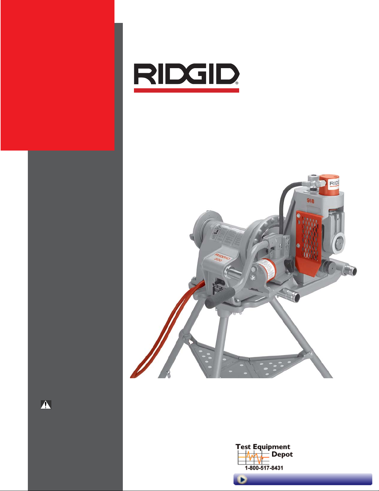
Roll Groover
OPERATOR’S
MANUAL
918
WARNING!
Read this Operator’s Manual
carefully before using this
tool. Failure to understand
and follow the contents of
this manual may result in
electrical shock, fire and/or
serious personal injury.
99 Washington Street
Melrose, MA 02176
Phone 781-665-1400
Toll Free 1-800-517-8431
Visit us at www.TestEquipmentDepot.com
Page 2
918 Roll Groover
Ridge Tool Company2
General Safety Information
WARNING! Read and understand all instructions. Failure
to follow all instructions listed below may
result in electric shock, fire, and/or serious
personal injury.
SAVE THESE INSTRUCTIONS!
Work Area Safety
• Keep your work area clean and well lit. Cluttered
benches and dark areas invite accidents.
• Do not operate electric tools in explosive atmo-
spheres, such as in the presence of flammable
liquids, gases, or dust. Electric motors create sparks
which may ignite the dust or fumes.
• Keep bystanders, children, and visitors away while
operating a tool. Distractions can cause you to lose
control.
• Keep floors dry and free of slippery materials such
as oil. Slippery floors invite accidents.
Electrical Safety
• Grounded tools must be plugged into an outlet,
properly installed and grounded in accordance
with all codes and ordinances. Never remove the
grounding prong or modify the plug in any way. Do
not use any adapter plugs. Check with a qualified
electrician if you are in doubt as to whether the outlet is properly grounded. If the tools should electrically
malfunction or break down, grounding provides a low
resistance path to carry electricity away from the user.
• Avoid body contact with grounded surfaces. There
is an increased risk of electrical shock if your body is
grounded.
• Don’t expose electrical tools to rain or wet condi-
tions. Water entering an electrical tool will increase the
risk of electrical shock.
• Do not abuse cord. Never use the cord to pull the
plug from an outlet. Keep cord away from heat, oil,
sharp edges or moving parts. Replace damaged
cords immediately. Damaged cords increase the risk
of electrical shock.
• When operating a tool outside, use an outdoor
extension cord marked “W-A” or “W”. These cords
are rated for outdoor use and reduce the risk of electrical shock.
• Keep all extension cord connections dry and off the
ground. Do not touch plugs with wet hands. This
practice reduces the risk of electrical shock.
• Use only three-wire extension cords which have
three-prong grounding plugs and three-pole receptacles which accept the machine plug. Use of
other extension cords will not ground the tool and increase the risk of electrical shock.
• Use proper extension cords.
(See chart.)
Insufficient
conductor size will cause excessive voltage drop, loss
of power.
Personal Safety
• Stay alert, watch what you are doing and use com-
mon sense when operating a tool. Do not use tools
while tired or under the influence of drugs, alcohol,
or medications. A moment of inattention while oper-
ating tools may result in serious personal injury.
• Dress properly. Do not wear loose clothing or jew-
elry. Contain long hair. Keep your hair and clothing
away from moving parts. Loose clothes, jewelry, or
long hair can be caught in moving parts.
• Avoid accidental starting. Be sure switch is OFF be-
fore plugging in. Plugging tools in that have the
switch ON invites accidents.
• Remove wrenches or adjusting keys before turning
the tool ON. A wrench or a key that is left attached to
a rotating part of the tool may result in personal injury.
• Do not over-reach. Keep proper footing and bal-
ance at all times. Proper footing and balance enables
better control of the tool in unexpected situations.
• Use safety equipment. Always wear eye protec-
tion. Dust mask, non-skid safety shoes, hard hat,
or hearing protection must be used for appropriate
conditions.
Grounding prong
Cover of
grounded
outlet box
Grounding prong
Minimum Wire Gauge for Extension Cord
Nameplate
Amps Total Length (in feet)
0-25 26-50 51-100
0-6 18 AWG 16 AWG 16 AWG
6-10 18 AWG 16 AWG 14 AWG
10-12 16 AWG 16 AWG 14 AWG
12-16 14 AWG 12 AWG
NOT RECOMMENDED
Page 3

918 Roll Groover
Ridge Tool Company 3
Tool Use and Care
• Do not use tool if switch does not turn it ON or
OFF. Any tool that cannot be controlled with the switch
is dangerous and must be repaired.
• Disconnect plug from the power source before
making any adjustments, changing accessories, or
storing the tool. Such preventive safety measures re-
duce risk of starting the tool accidentally.
• Store idle tools out of the reach of children and
other untrained persons. Tools are dangerous in
the hands of untrained users.
• Check for misalignment or binding of moving parts,
breakage of parts, and any other condition that
may affect the tool’s operation. If damaged, have
the tool serviced before using. Many accidents are
caused by poorly maintained tools.
• Use only accessories that are recommended by the
manufacturer for your model. Accessories that may
be suitable for one tool may become hazardous when
used on another tool.
• Keep handles dry and clean; free from oil and
grease. This allows for better control of the tool.
Service
• Tool service must be performed only by qualified
repair personnel. Service or maintenance performed
by unqualified repair personnel could result in injury.
• When servicing a tool, use only identical replace-
ment parts. Follow instructions in the Maintenance
Section of this manual. Use of unauthorized parts or
failure to follow maintenance instructions may create a
risk of electrical shock or injury.
Specific Safety Information
WARNING
Foot Switch Safety
Using a threading machine without a foot switch increases
the risk of serious injury. A foot switch provides better
control by letting you shut off the motor by removing your
foot. If clothing should become caught in the machine, it will
continue to wind up, pulling you into the machine. Because
the machine has high torque, the clothing itself can bind
around your arm or other body parts with enough force to
crush or break bones.
Roll Groover Safety
• Roll Groover is made to groove pipe and tubing.
Follow instructions in Operator’s Manual on machine uses. Other uses may increase the risk of injury.
• Keep hands away from grooving rolls. Do not wear
loose fitting gloves when operating unit. Fingers
could get caught between grooving and drive rolls.
• Keep guards in place. Do not operate the groover
with guard removed. Exposure to grooving rolls may
result in entanglement and serious injury.
• Set-up Groover on a flat, level surface. Be sure
the machine, stand, and groover are stable. Will prevent tipping of the unit.
• Do not wear loose clothing. Keep sleeves and
jackets buttoned. Do not reach across the machine or pipe. Clothing can be caught by the pipe
resulting in entanglement and serious injury.
• Do not use this Roll Groover with a Power Drive or
Threading Machine that does not have a foot
switch. Foot switch is a safety device to prevent seri-
ous injury.
• When grooving pipe, keep hands away from the
end of the pipe. Do not reach inside pipe end. Will
prevent being cut on sharp edges and burrs.
• Be sure groover is properly secured to the power
drive or threading machine. Carefully follow the setup procedures. Will prevent tipping of the pipe or
grooving unit.
• Properly support pipe with pipe stands. Use two
pipe stands to groove pipe over 36″ long. Prevents
tipping of the unit.
• Use only power drives and threading machines
that operate under 58 RPM. Higher speed machines
increase the risk of injury.
• Lock foot switch when not in use.
(See Figure 1.)
Avoids accidental starting.
Figure 1 – Locked Foot Switch
WARNING
Read this operator’s manual carefully before using
the Roll Groover. Failure to understand and follow
the contents of this manual may result in electrical
shock, fire and/or serious personal injury.
Page 4
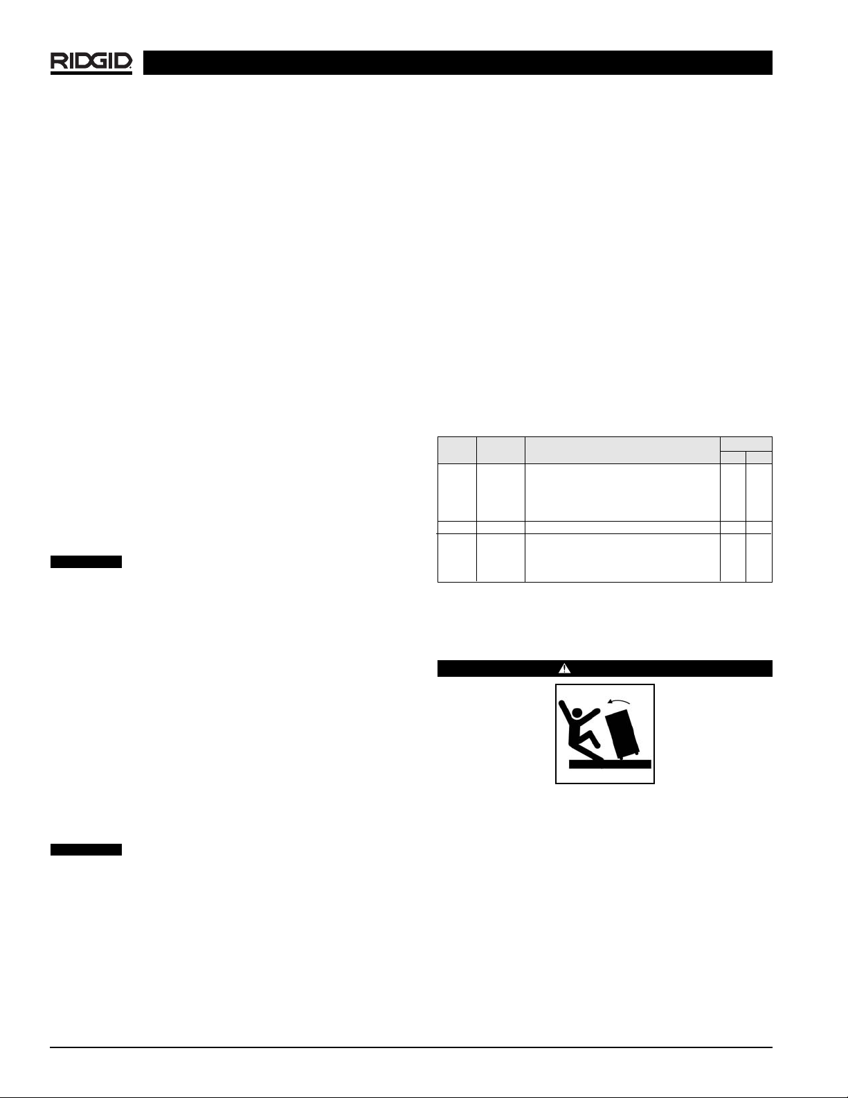
Used in Conjunction with the Following Power
Drives and Threading Machines
• 300 Power Drive (38 and 57 RPM)
• 535 Threading Machine (38 and 54 RPM)
• 1822 Threading Machine
• 1224 Threading Machine
• 535 Automatic Threading Machine
Standard Equipment
918 Roll Groover Only
• 918 Groover with 2″ – 6″ drive shaft and groove set
•8″ – 12″ Drive shaft and groove set
• Carrying case for drive shaft and groove set
•1/8″ T-Handle hex wrench (groove roll change out)
• Wrench (drive shaft changeout)
918 Roll Groover Models
Roll Groover Assembly
Instructions
WARNING
The 918 Roll Groover should only be used with the
following power drives and threading machines.
• 300 Power Drive (38 and 57 RPM)
• 535 Threading Machine (38 and 54 RPM)
• 1822 Threading Machine
• 1224 Threading Machine
• 535 Automatic Threading Machine
Use only power drives and threading machines
that operate at 58 RPM or less. Higher speed machines increase risk of injury.
To prevent serious injury, proper assembly of the
Roll Groover is required. The following procedures
should be followed:
918 Roll Groover
Ridge Tool Company4
Description, Specifications and
Standard Equipment
Description
The RIDGID 918 Heavy Duty Roll Groover forms rolled
grooves in steel, stainless steel, aluminum, PVC pipe and
copper tubing. The grooves are formed by the hydraulic
feeding of a grooving roll into the pipe which is supported by a drive roll.
The 918 Roll Groover includes two (2) groove and drive
shaft sets that can groove the following pipe:
•2″ – 6″ Schedule 10 and 40
•8″ – 12″ Schedule 10 and 8″ Schedule 40
With additional roll sets, the groover can also be adapted
to groove the following:
•2″ – 6″ copper tubing (Types K, L, M, DWV);
•1″ Schedule 10 and 40;
•11/4″ – 11/2″ Schedule 10 and 40.
The 918 Heavy Duty Roll Groover is specifically designed
for use with the RIDGID 300 Power Drive, as well as
RIDGID 535, 535A, 1822, and 1224 Threading Machines.
Different mounting kits are required for each power source.
When properly used, the Model 918 makes
grooves that are dimensionally within the specifications of
AWWA C606-87. Selection of appropriate materials and
joining methods is the responsibility of the system designer and/or installer. Before any installation is attempted,
careful evaluation of the specific service environment, including chemical environment and service temperature,
should be completed.
Specifications
Roll Grooving Capacity
(See Table II for wall thickness)
•1″ – 12″ Schedule 10
•1″ – 8″ Schedule 40
•2″ – 6″ Copper types K, L, M, DWV
•2″ – 8″ Schedule 40 PVC
Do not use to groove 8″ schedule 40 steel
pipe harder than 150 BHN. Doing so may result in improperly formed grooves that do not meet required
specifications.
Depth Adjustment ..........Indexed adjustment knob
Actuation ........................Hydraulic hand pump
CAUTION
Catalog Model Weight
No. No. Description lb. kg.
48297 918-1 918 Roll Groover w/300 Power Drive Mount Kit 81 36,7
48377 918-2 918 Roll Groover w/1822 Carriage Mount Kit 81 36,7
48382 918-4 918 Roll Groover w/1224 Carriage Mount Kit 81 36,7
48387 918-5 918 Roll Groover w/535 Carriage Mount Kit 81 36,7
47222 918 Only 918 Roll Groover Only 75 34,0
Mounting Kit Only
48292 911 300 Power Drive Mount Kit Only 9 4
48392 912 1822 Carriage Mount Kit Only 39 17,7
48397 914 1224 Carriage Mount Kit Only 36 16,4
48402 915 535 Carriage Mount Kit Only 22 10
CAUTION
Page 5

918 Roll Groover
Ridge Tool Company 5
Installing the 918-1 Roll Groover on the
300 Power Drive
Figure 2 – Installing on 300 Power Drive
1. Remove carriage or other attachments from the 300
Power Drive.
2. Fully open front chuck of power drive.
3. Slide the base assembly onto the support arms of the
300 Power Drive.
(Figure 2)
4. Align the notched flats of the drive shaft with the
jaws on the 300 Power Drive chuck.
5. Close and tighten the front chuck.
Installing the 918-2 Roll Groover on the
1822 Threading Machine
Sub-Assembly
1. Position 918 Roll Groover on the mounting base as
shown in
Figure 3
.
2. Install and tighten the (2) 1/2″ x 11/4″ hex bolts which
connect 918 to mounting base.
3. Position hydraulic pump and securely bolt in place
with (4) 1/4″ x 3/4″ hex bolts.
4. Attach drive bar adapter to roll groover by tightening
two (2) set screws.
Figure 3 – 918 Heavy Duty Roll Groover on 1822 Mounting
Base
Installing on 1822 Threading Machine with 1406
Stand
1. Position carriage towards front chuck and swing tools
to the rear position. Remove carriage stop pin at the
end of rail.
Position reamer inside the die head to
prevent accidental contact.
2. Front chuck must be open. Position 918-2 so that the
base slides onto the support rails and drive bar feeds
into open chuck.
3. Place carriage stop pin in support rail hole.
4. Install support legs into socket holes on the base.
(Figure 4)
and tighten locking bolts.
Drive bar must be centered in front chuck
jaws. All bolts must be tight and the drive bar must be
securely held in chuck when closed.
Installing on 1822 Threading Machine with 100,
150, or 200 Stands
1. Position carriage towards front chuck and swing tools
to the rear position. Remove carriage stop pin at the
end of the rail.
Position reamer inside the die head to
prevent accidental contact.
2. Front chuck must be open. Position 918-2 so that the
base slides onto the support rails and drive bar feeds
into open chuck.
3. Replace carriage stop pin in support rail hole.
Drive Bar
Hydraulic
Pump
Mounting
Base
1
/
4
″ x
3
/
4
″
Bolts (4)
1
/
2
″ x 1
1
/
4
″
Bolts (2)
CAUTION
WARNING
CAUTION
Page 6
918 Roll Groover
Ridge Tool Company6
NOTE! Support legs are not needed when when using
these stands.
Drive bar must be centered in front chuck
jaws. All bolts must be tight and the drive bar must be
securely held in chuck when closed.
Figure 4 – 918 Roll Groover Mounted on 1822 with 1406
Stand
Installing the 918-4 Roll Groover on the
1224 Threading Machine
Sub-Assembly
1. Align housing plate in recessed area of 1224.
2. Align 918 on the 1224 mounting base.
(Figure 5)
3. Install and tighten the (2) 1/2″ x 11/4″ hex bolts which
connect the 918 to mounting base.
4. Attach pump bracket with the two (2) 3/8″ x 1/2″ hex
bolts.
5. Position hydraulic pump and securely bolt in place
with (4) 1/4″ x 3/4″ hex bolts.
6. Attach drive bar adapter to roll groover by tightening
(2) set screws.
Figure 5 – 918 Heavy Duty Roll Groover on 1224
Threading Machine Mounting Base
Installing on 1224 Threading Machine
1. Position carriage towards front chuck and swing carriage tools to rear position.
Position reamer inside the die head to
prevent accidental contact.
2. Place 918-4 on the far side carriage rail and lower
onto near side rail.
(Figure 6)
3. Position base so that the drive bar feeds into the
open chuck.
4. Tighten chuck jaws securely into drive bar.
Drive bar must be centered in front chuck
jaws. All bolts must be tight and the drive bar must be securely held in chuck.
Front Chuck
Foot Switch
Drive Bar
Carriage
918-2
Sub-assembly
Hydraulic Pump
1224
Mounting
Base
1
/4″ x 3/4″ bolts (4)
for mounting
hydraulic pump
1
/2″ x 11/4″ bolts (2)
for mounting base
Support
Leg
Support
Leg
WARNING
1406
Stand
Housing
Plate
CAUTION
WARNING
Page 7
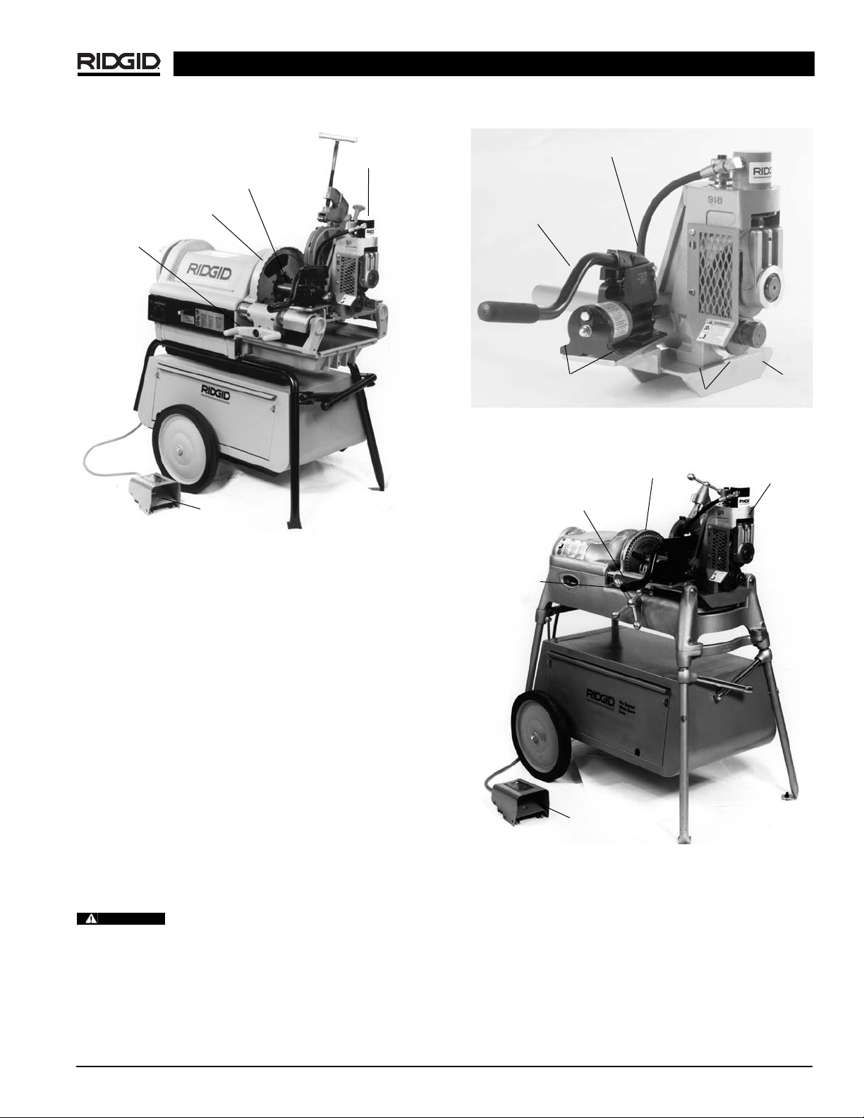
Ridge Tool Company 7
Figure 6 – 918-4 Roll Groover on 1224 Threading Machine
Installing the 918-5 Heavy Duty Roll
Groover on the 535 Manual and
Automatic Threading Machines
Sub-Assembly
1. Position 918 Roll groover on the mounting base as
shown.
(Figure 7)
2. Install and tighten the (2) 1/2″ x 11/4″ hex bolts which
connect 918 to mounting base.
3. Position hydraulic pump and securely bolt in place with
(4)1/4″ x 3/4″ hex bolts.
4. Attach drive bar adapter to roll groover by tightening
two (2) set screws.
Installing on 535 Manual and Automatic Threading
Machines
1. Position carriage towards front chuck and swing carriage tools to the rear position.
Position reamer inside the die head to
pre vent accidental contact.
2. Place 918-5 on far side of carriage rail, lower onto front
rail and tighten front chuck
(Figure 8).
3. Position base so that drive bar feeds into open chuck.
4. Tighten chuck jaws securely on to drive bar.
Figure 7 – 918 Roll Groover on 535 Threading Machine
Mounting Base
Figure 8 – 918-5 Roll Groover on 535 Threading Machine
918 Roll Groover
918-4
Sub-assembly
Drive Bar
Front Chuck
Carriage
Foot Switch
Drive Bar
Hydraulic
Pump
1
/4″ x 3/4″ Bolts (4)
1
/2″ x 11/4″ Bolts (2)
Mounting
Base
918-5
Sub-assembly
Front Chuck
Drive Bar
Carriage
Foot Switch
CAUTION
Page 8
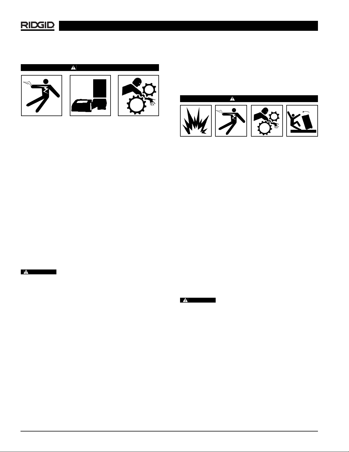
918 Roll Groover
Ridge Tool Company8
Machine Inspection
WARNING
Do not use this Roll Groover with a power drive or
threading machine that does not have a foot switch.
To prevent serious injury, inspect your Roll Groover
and machine. The following inspection procedures
should be performed on a daily basis.
1. Make sure machine is unplugged and the directional
switch is set to the OFF position.
2. Make sure the foot switch is present and attached to
the machine.
3. Inspect the power cord and plug for damage. If the
plug has been modified, is missing the grounding pin
or if the cord is damaged, do not use the machine until
the cord has been replaced.
4. Make sure all bolts holding the Roll Groover and hydraulic pump to the base are tight.
5. Drive bar must be centered and securely held in the
front chuck.
6. Check that guard mounted to the roll groover is in
place
(Figure 3)
.
Do not operate Roll Groover with guard
removed. Exposure to moving grooving rolls may result in fingers being crushed.
7. Inspect the Roll Groover and machine for any broken,
missing, misaligned or binding parts as well as any
other conditions which may affect the safe and normal
operation of this equipment. If any of these conditions
are present, do not use the Roll Groover until any
problem has been repaired.
8. Lubricate the Roll Groover if necessary according to
the Maintenance Instructions.
9. Use groover rolls and accessories that are designed
for your Roll Groover and meet the needs of your application. The correct groover tools and accessories
allow you to do the job successfully and safely. Ac cessories suitable for use with other equipment may
be hazardous when used with this Roll Groover.
10. Clean any oil, grease or dirt from all equipment handles and controls. This reduces the risk of injury due
to a tool or control slipping from your grip.
11. Inspect the groove rolls to insure they are not damaged or worn. Worn groover rolls can lead to pipe
slippage and poor quality grooves.
Machine and Work Area Set-Up
WARNING
To prevent serious injury, proper set-up of the machine
and work area is required. The following procedures
should be followed to set-up the machine:
1. Locate a work area that has the following:
• Adequate lighting
• No flammable liquids, vapors or dust that may ignite.
• Grounded electrical outlet
• Clear path to the electrical outlet that does not
contain any sources of heat or oil, sharp edges or
moving parts that may damage electrical cord.
• Dry place for machine and operator. Do not use
the machine while standing in water.
• Level ground
2. Clean up the work area prior to setting up any equipment. Always wipe up any oil that may be present.
3. Place machine on a flat level surface. Be sure the machine, stand and groover are stable.
4. Properly support the pipe with pipe stands. See
Chart
“A”
for maximum pipe lengths to be grooved with
one stand.
Failure to properly support the pipe can
result in the unit tipping or the pipe falling.
5. Make sure FOR/OFF/REV switch is in the OFF position.
6. Position the foot switch so that the operator can
safely control the machine, roll groover and workpiece. It should allow the operator to do the following:
• Stand facing the hydraulic pump.
• Use the foot switch with his left foot.
• Have convenient access to the groover and hydrau -
lic controls without reaching across the machine.
Machine is designed for one person operation.
7. Plug the machine into the electrical outlet making
sure to position the power cord along the clear path
selected earlier. If the power cord does not reach
the outlet, use an extension cord in good condition.
WARNING
WARNING
Page 9
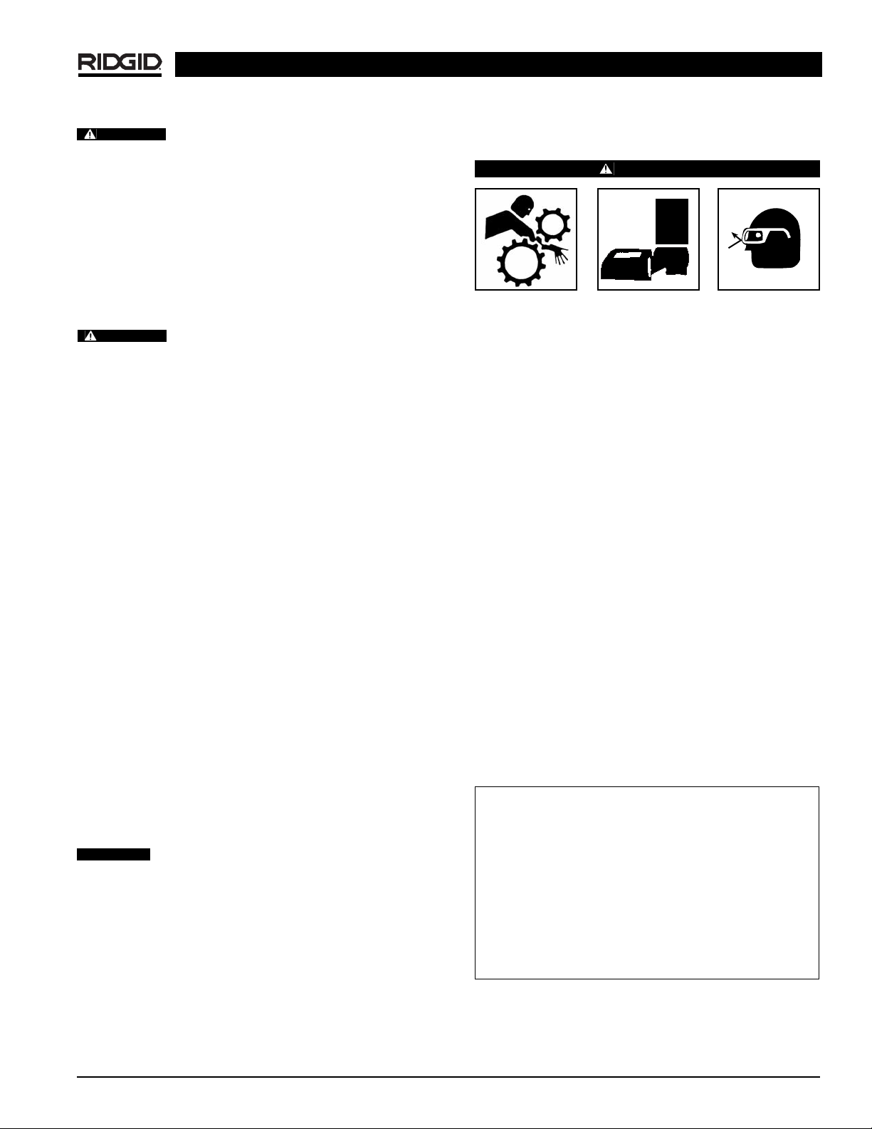
918 Roll Groover
Ridge Tool Company 9
To avoid electrical shock and electrical fires,
never use an extension cord that is damaged or does not
meet the following requirements.
• The cord has a three-prong plug similar to shown in
Electrical Safety section.
• The cord is rated as “W” or “W-A” if being used outdoors.
• The cord has sufficient wire thickness (14 AWG
below 25′/12AWG 25′ - 50′). If the wire thickness is
too small, the cord may overheat, melting the cord’s
insulation or causing nearby objects to ignite.
To reduce risk of electrical shock, keep all
electrical connections dry and off he ground. Do not touch
plug with wet hands.
8. Check the unit to insure it is operating properly.
• Flip the directional switch to FOR (Forward). Press
and release the foot switch. Check that the groove
roll rotates in a counterclockwise direction as you
are facing the groover. Have the power drive or
threading machine serviced if it rotates in the wrong
direction or if the foot switch does not control its
stopping or starting.
• Depress and hold the foot switch. Inspect the moving parts for misalignment, binding, odd noises or any
other unusual conditions that may affect the safe and
normal operation of the machine. If such conditions
are present, have the roll groover drive serviced.
• Check the speed of the machine to insure it rotates
under 58 RPM. Higher speed machine increases
the risk of injury.
• Flip the directional switch to REV (Reverse) (Except
1822-I and 535 Automatic machines). Press and
release the foot switch. Check that the drive roll rotates in a clockwise direction as you are facing the
roll groover.
• Release the foot switch and flip the directional
switch to OFF.
9. Check the groove and drive rolls to insure they are the
correct size.
Use of roll sets on both carbon and stainless
steel pipe can lead to contamination of the stainless steel
material. This contamination could cause corrosion and premature pipe failure. To prevent ferrous contamination, use
roll sets dedicated for stainless steel grooving.
Operating the 918 Roll Groover
WARNING
Do not wear loose clothing when operating a Roll
Groover. Keep sleeves and jackets buttoned. Do
not reach across the machine or pipe.
Do not use this Roll Groover with a Power Drive or
Threading Machine that has a broken or missing foot
switch. Always wear eye protection to protect eyes
from dirt and other foreign objects.
Keep hands away from grooving rolls. Do not wear
loose fitting gloves when operating groover. Use
pipe stands to support pipe.
Pipe Preparation
1. Pipe ends must be cut square. Do not use cutting
torch.
2. Pipe out-of-roundness must not exceed the
total O.D. tolerance listed in groove specifications,
Table 1
.
NOTE! Determine out-of-roundness by measuring max-
imum and minimum O.D. at 90 degrees apart.
3. All internal or external weld beads, flash or seams
must be ground flush at least 2″ back from pipe end.
NOTE! Do not cut flats on gasket seat area.
Pipe/Tubing Length
Chart A lists the minimum length of pipe or tubing to be
grooved and the maximum length to be grooved with (1)
pipe stand.
Pipe Set-Up
1. Pipe or tubing longer than the specified maximum
Groovable Pipe Lengths – Inches
Nom. Min. Max. Nom. Min. Max.
Size Length Length Size Length Length
1 8 36 4 8 36
1
1
/
4
8364
1
/
2
832
1
1
/
2
836 5 832
2 8 36 6 O.D. 10 30
2
1
/
2
8 36 6 10 28
383681024
3
1
/
2
836101024
12 10 24
Chart A – Minimum/Maximum Pipe Length
WARNING
WARNING
CAUTION
Page 10
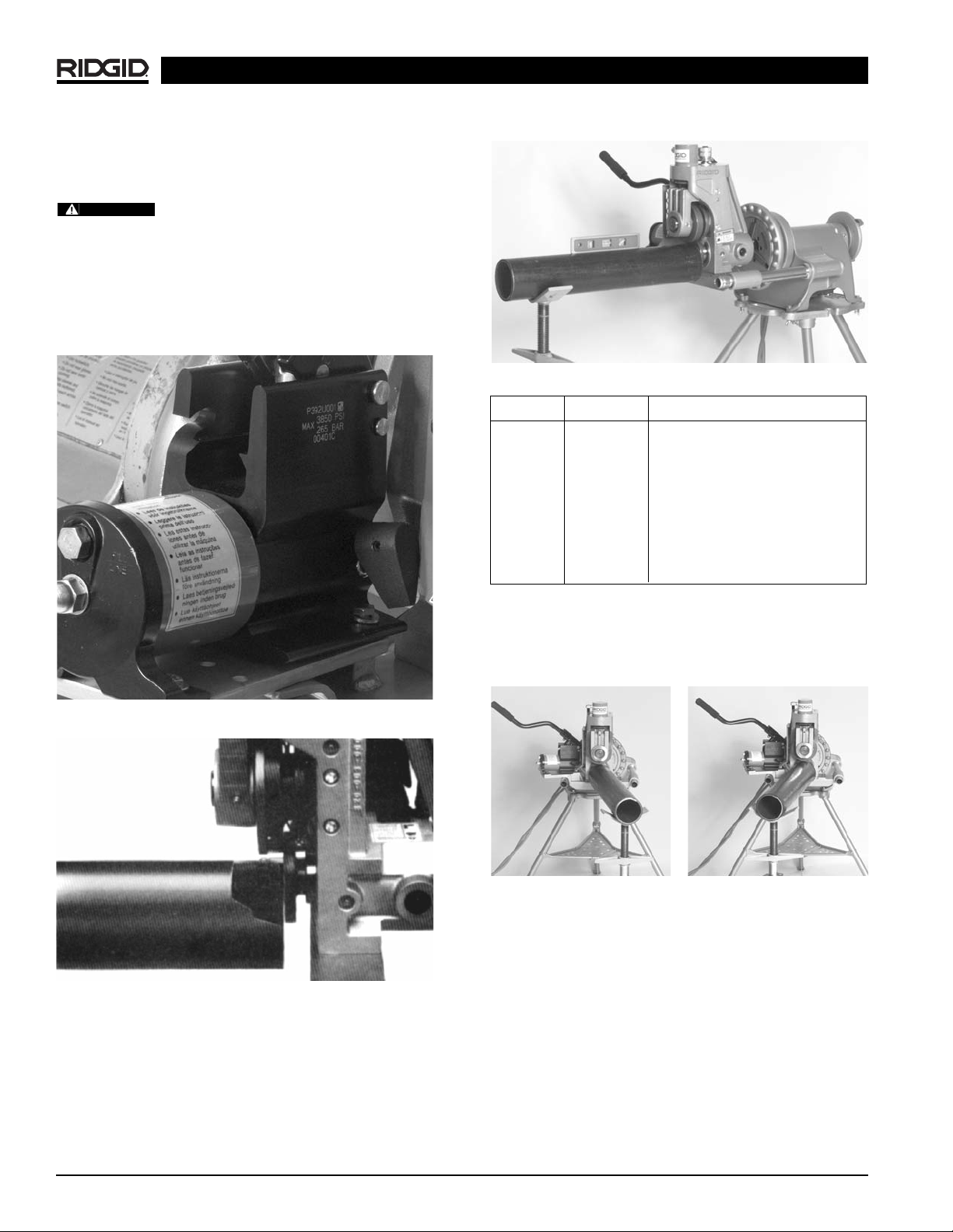
918 Roll Groover
Ridge Tool Company10
lengths listed in
Chart A
must be supported with 2
pipe stands. The second pipe support should be located 3/4of pipe length from roll groover.
Failure to use two stands may result in the
unit tipping or the pipe falling.
2. Raise upper groove roll housing by placing pump release lever in RETURN position (away from operator).
(Figure 9)
3. Square pipe and pipe support to roll groover making
sure pipe is flush against drive roll flange.
(Figure 10)
Figure 9 – Close-Up of Release Lever on 918 Pump
Figure 10 – Close-Up of Pipe Against Drive Roll Flange
4. Level pipe by adjusting pipe stand.
(Figure 11)
5. Slightly offset pipe and pipe stand (approx. 1/2° away
from or toward operator as directed below:
Figure 11 – Leveling Pipe on Pipe Support and 918
NOTE! If running machine in forward, offset pipe 1/2°
away from operator.
(Figure 12)
NOTE! If running machine in reverse, offset pipe 1/2°
toward operator.
(Figure 13)
Adjusting Roll Groove Depth
NOTE! Due to differing pipe characteristics, a test groove
should always be performed when setting up or
changing pipe sizes. The index depth adjustment
knob must be reset for each diameter of pipe/tube.
1. Advance the upper groove roll by placing the pump release lever in ADVANCE position (toward operator)
and pump the handle until the upper roll contacts the
pipe to be grooved.
Figure 12 – Offset Pipe on
918 in
FORWARD
Position
Figure 13 – Offset Pipe on
918 in
REVERSE
Position
Mount Setting Degree
300 REV
1
/2° toward operator
300 FOR
1
/2° away from operator
1822 FOR
1
/2° away from operator
1224 REV
1
/2° toward operator
1224 FOR
1
/2° away from operator
535 REV
1
/2° toward operator
535 FOR
1
/2° away from operator
WARNING
Page 11
918 Roll Groover
Ridge Tool Company 11
NOTE! Upper roll should only touch the pipe surface.
Care must be taken not to penetrate pipe surface
with upper roll by applying excessive pressure.
2. Turn down the indexed depth adjustment knob (clockwise) until it stops against the top of the machine.
3. Back the depth adjustment knob off one turn.
(Figure
14)
Figure 14 – Close-Up of Depth Adjustment Knob Backed
Up with Gap Between Bottom of Knob and
Casting
Forming the Roll Groove
Pipe wall thickness cannot exceed the maximum wall thickness specified in the “Pipe Max i mum
and Minimum Wall Thickness” Table II. Do not use to
groove 8″ schedule 40 steel pipe harder than 150 BHN.
1. Flip the directional switch from OFF and step on
power drive or threading machine foot switch while applying downward pressure on the 918 pump handle.
Allow one full pipe rotation between quarter strokes of
the pump handle.
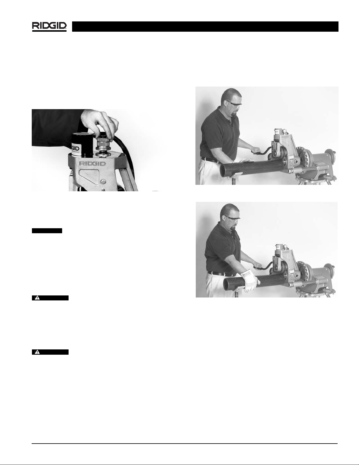
If pipe begins to “walk off” the drive roll,
stop the machine and check “Pipe Set-Up” procedure.
2. To help prevent “walking”, apply pressure on outside of
pipe with right hand: away from operator when running
the power drive or machine in FORWARD mode
(Figure 15)
; toward operator when running the power
drive or machine in REVERSE mode
(Figure 16)
Keep hands away from the end of pipe.
Do not reach inside pipe end. Will prevent being cut on
sharp edges and burrs.
NOTE! Do not overfeed upper groove roll. Maintain con-
stant downward pressure, pausing to allow one
pipe revolution per quarter stroke of the pump
handle.
3. When the depth adjustment knob contacts the machine casting, allow two complete pipe revolutions
to even out groove depth.
4. Release foot switch and retract upper groove roll by
placing the pump release lever in the RETURN position (toward operator).
5. Check groove diameter before proceeding with additional grooves.
Figure 15 – Applying Pressure on Pipe with Power Drive
in FORWARD Mode
Figure 16 – Applying Pressure on Pipe with Power Drive
in REV Mode.
NOTE! Groove diameter should be measured using a
Diameter - tape. To increase groove depth, rotate
the index depth adjustment knob one mark count er clockwise. To decrease groove depth, rotate the
depth adjustment knob clockwise.
6. Periodically check groove with a Diameter-Tape or
similar measuring device.
Roll Grooving Tips with 918
1. If pipe tends to “walk off” drive roll, increase offset dimension.
(Figures 12 & 13)
2. If drive roll flange shaves pipe end, decrease offset dimension.
3. If pipe end flare is excessive, lower pipe end to level
with roll groover.
WARNING
CAUTION
WARNING
Page 12
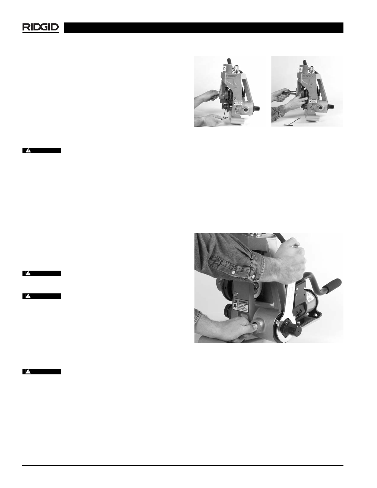
3. Removing Solid Drive Shaft:
• Manually rotate the drive shaft while applying
pressure to the spindle lock pin until the lock pin
engages the spindle lock hole in the driveshaft.
• With the spindle lock engaged, use the box wrench
to remove the drive shaft bearing retaining nut
(Figure 19)
.
• Release pressure on the spindle lock pin, allowing
to retract.
• Remove the drive shaft
(Figure 20)
.
Figure 19 – Engaging Spindle Lock and Removing Drive
Shaft Retaining Nut
918 Roll Groover
Ridge Tool Company12
4. If pipe wobbles and/or “walks off” the drive roll, raise
pipe end to level with roll groover.
5. Short lengths of pipe (under three feet) may require
slight pressure to maintain the
1
/2degree offset di-
mension.
Grooving Short Lengths of Pipe
1. When running machine in forward direction, exert
pressure on pipe away from operator.
(Figure 15)
2. When running machine in reverse, exert pressure
on pipe toward operator.
(Figure 16)
Do not attempt to groove any pieces of
pipe shorter than 8″. Increases risk of fingers being
crushed in the grooving rolls.
Removing and Installing
Groove Roll and Drive Shaft
NOTE! As groove dimensions are determined by the roll
set geometry, specific roll sets are required
when grooving the following:
• 2″ – 6″ Schedule 10, 40
• 8″ – 12″ Schedule 10
• 8″ Schedule 40
• 2″ – 6″ Copper tubing (Types K, L, M, DWV)
• 1″ Schedule 10, 40
• 1
1
/4″ - 11/2″ Schedule 10, 40
Make sure power drive or threading machine is unplugged from power source before changing
the Roll Sets or removing the Roll Groover.
When removing rolls and shafts, be sure
they are properly supported.
Removing and Installing Roll Sets with
Solid Drive Shafts (2″ – 6″, 8″ – 12″)
1. Recommend removing 918 Roll Groover from power
drive or machine, and placing it on a work bench in an
upright position. If a suitable workplace is not available,
roll sets can be changed with Groover mounted on the
machine.
Use care that the Groover does not slide
off the support arms on the Model 300 Power Drive.
2. Removing Groove Rolls:
• Fully raise the upper roll housing by moving the
pump release lever to the return position, away
from the operator.
• Loosen groove roll set screw
(Figure 17)
. Grasp
groove roll and remove upper shaft and groove roll
from groover
(Figure 18)
.
Figure 17 – Loosening
Grooving Roll
Set Screw
Figure 18 – Removing
Retain ing Shaft
and Groove Roll
WARNING
WARNING
WARNING
WARNING
Page 13
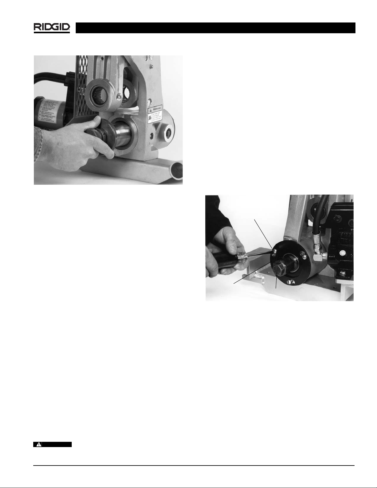
Figure 20 – Removing Drive Shaft
4. Installing Solid Drive Shaft:
• Install new drive shaft.
• Install the drive shaft bearing retaining nut, with
text out.
• Manually rotate the drive shaft while applying
pressure to the spindle lock pin until the lock pin
engages the spindle lock hole in the drive shaft.
• With the spindle lock engaged, use the box wrench
to tighten the drive shaft bearing retaining nut.
• Release pressure on the spindle lock pin, allowing
to retract.
5. Installing groove roll:
• With upper roll housing fully raised and driveshaft
in place, insert groove roll into upper roll assembly
and fully insert upper roll shaft through bearings
and groove roll.
• Tighten groove roll set screw into detent on upper
roll shaft.
6. Using a grease gun, grease the drive shaft through
the fitting on the side of the Groover.
Removing and Installing Roll Sets with
Two-Piece Drive Shafts
(1″, 1
1
/4″ – 11/2″, 2″ – 6″ Copper)
1. Recommend removing 918 Roll Groover from power
drive or machine, and placing it on workbench in an
upright position. If a suitable workplace is not available, roll sets can be changed with the Roll Groover
mounted in the machine.
Use care that the Groover does not slide
off the support arms on the 300 Power Drive.
2. Removing groove roll:
• Fully raise the upper roll housing by moving the
pump release lever to the return position, away
from the operator.
• Loosen groove roll set screw
(Figure 17)
. Grasp
groove roll and remove upper shaft and groove roll
from the Groover
(Figure 18)
.
3. Removing drive shaft:
• Manually rotate the drive shaft while applying
pressure to the spindle lock pin until the lock pin
engages the spindle lock hole in the drive shaft.
• With the spindle lock engaged, use a wrench to
loosen the draw bolt
(Figure 21)
.
• Tap draw bolt with a mallet to release drive roll
from drive shaft.
• Unthread draw bolt from drive roll, remove drive roll.
Figure 21 – Loosening Draw Bolt and Retaining Plate
Hex Screws
4. Installing new drive roll:
• Install new drive roll, insert and hand tighten draw
bolt.
• Manually rotate the drive shaft/drive roll assembly
while applying pressure to the spindle lock pin
until the lock pin engages the spindle lock hole in
the drive shaft.
• With the spindle lock engaged, use a wrench to
tighten the draw bolt.
• Release pressure on the spindle lock pin, allowing
to retract.
5. Installing Groove Roll:
• With upper roll housing fully raised and drive shaft
in place, insert groove roll into upper roll assembly
and fully insert upper roll shaft through bearings
and groove roll.
918 Roll Groover
Ridge Tool Company 13
Loosen Screws
Rear Bearing
Retaining Plate
WARNING
Draw Bolt
Page 14
918 Roll Groover
Ridge Tool Company14
• Tighten groove roll set screw into detent on upper
roll shaft.
6. Using a grease gun, grease the drive shaft through
the fitting on the side of the Groover.
Changing from Solid Drive Shaft Roll
Set to Two-Piece Drive Shaft
1. Recommended removing 918 Roll Groover from
power drive or machine, and placing it on workbench
in an upright position. If a suitable workplace is not
available, roll sets can be changed with the Roll
Groover mounted on the machine.
Use care that the Groover does not slide
off the support arms on the 300 Power Drive.
2. Removing groove roll:
• Fully raise the upper roll housing by moving the
pump release lever to the return position, away
from the operator.
• Loosen groove roll set screw
(Figure 17)
. Grasp
groove roll and remove upper roll shaft and groove
roll from Groover
(Figure 18)
.
3. Changing solid drive shaft rollset to two-piece drive
shaft:
• Manually rotate the drive shaft while applying
pressure to the spindle lock pin until the lock pin
engages the spindle lock hole in the drive shaft.
• With the spindle lock engaged, use the box wrench
to remove the drive shaft bearing retaining nut
(Fi -
gure 19)
.
• Release pressure on the spindle lock pin, allowing
to retract.
• Remove the drive shaft
(Figure 20)
.
• Remove the three 1/4″ bolts that hold the retaining
plate in place, remove retaining plate, remove bearing
(Figure 21)
.
• Insert drive shaft/bearing assembly (for two-piece
driveshaft) into Groover. Replace retaining plate
and bolt, tighten bolts.
• Install new drive roll, insert and hand tighten draw
bolt.
• Manually rotate the drive shaft/drive roll assembly
while applying pressure to the spindle lock pin until
the lock pin engages the spindle lock hole in the
drive shaft.
• With the spindle lock engaged, use a wrench to
tighten the draw bolt.
• Release pressure on the spindle lock pin, allowing
to retract.
4. Installing groove roll:
• With upper housing fully raised and drive shaft in
place, insert groove roll into upper roll assembly
and fully insert upper roll shaft through bearings
and groove roll.
• Tighten groove roll set screw into detent on upper
roll shaft.
5. Using a grease gun, grease the drive shaft through
the fitting on the side of the Groover.
Installing and Operating Pipe
Stabilizer/Nipple Bracket
NOTE! The pipe stabilizer/nipple bracket works on 300
Power Drive Mounting only. Use for grooving
nipples and pipe 21/2″ through 12″ nominal pipe
sizes.
Make sure machine is unplugged from
power source before installing pipe stabilizer/nipple.
Installation
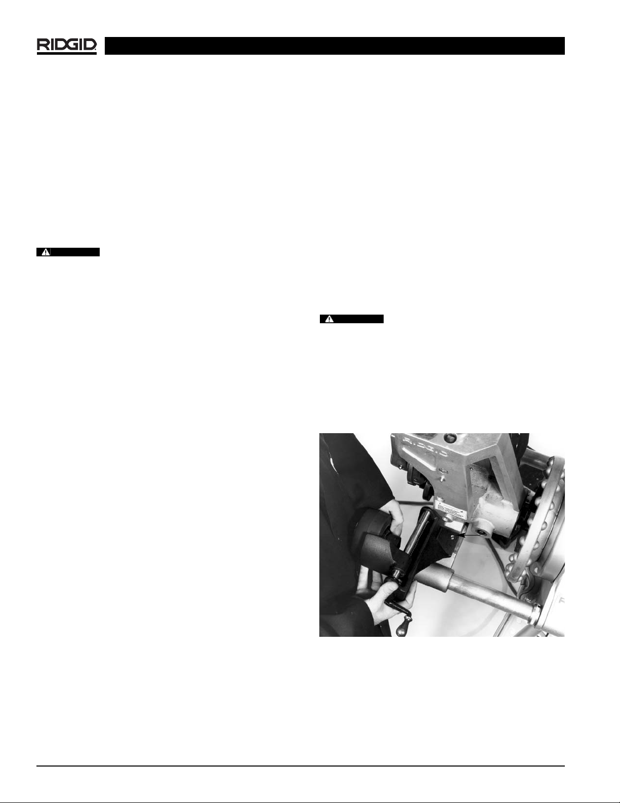
1. Align mounting bracket onto base of roll groover so
that the bolt holes in the mounting bracket line up with
bolt holes in the base.
(Figure 22)
2. Install and tighten two bolts through the bottom of the
roll groover base.
Figure 22 – Line Up Bolt Holes in the Mounting Bracket
with Bolt Holes in the Base
Stabilizer Operation
NOTE! Once the stabilizer is adjusted for a selected
pipe diameter, it does not have to be readjusted.
1. Place pipe on to drive roll on Model 918 Roll Groover.
WARNING
WARNING
Page 15
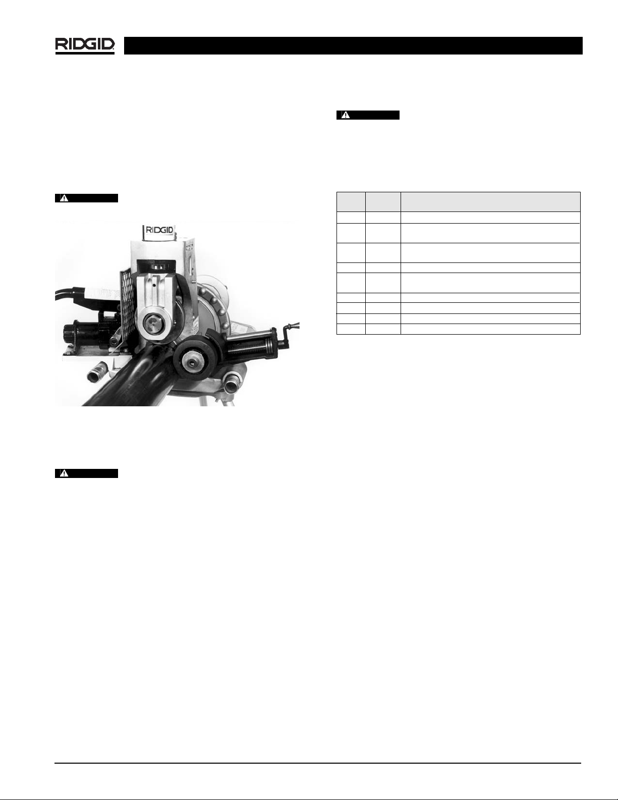
2. Properly set-up pipe to ensure pipe is level and
square on the shoulder of the drive roll.
3. Engage hydraulic pump and bring groove roll (upper
roll) down until it contacts the pipe.
4. Tighten stabilizer roll until roll contacts the pipe.
Continue to tighten stabilizer one full turn after contacting workpiece
(Figure 23).
Do not reach across pipe to adjust stabi-
lizer.
NOTE! If pipe “walks off” the drive shaft, tighten stabi-
lizer
1
/2turn.
Do not use the pipe stabilizer/nipple
bracket on 8″ or shorter workpieces. Increases risk of fingers being crushed in the grooving rolls.
918 Roll Groover
Ridge Tool Company 15
Figure 23 – Stabilizer Positioning
Accessories
Only the following RIDGID products have
been designed to function with the 918 Roll Groover.
Other accessories suitable for use with other tools may become hazardous when used on this Roll Groover.
To prevent serious injury, use only the accessories listed
below.
NOTE! A Roll Set consists of a Groove Roll and a Drive Roll.
Catalog Model
No. No. 918 Accessories
48405 — Roll Set for 8″ Sch. 40, Tool Box Included
48407 — Roll Set for 1
1
/4″ to 11/2″ Sch. 10/40.
Tool Box Includes Drive Shaft, Bolt and Tools
48412 — Roll Set for 1″ Sch. 10/40 and 1
1
/4″ to 11/2″ Sch. 10/40.
Tool Box Includes Drive Shaft, Bolt and Tools
48417 — Roll Set for Copper (2″ - 6″) Types K, L, M and DWV
59992 — 1″ - 12″ Stabilizer for Grooving Nipples.
For 918 w/300 Mounting Kit or 918-I
49662 — Tool Box
76822 — English Diameter Tape
76827 — Metric Diameter Tape
Pipe Stands (See Ridge Tool Catalog)
WARNING
WARNING
WARNING
Page 16
918 Roll Groover
Ridge Tool Company16
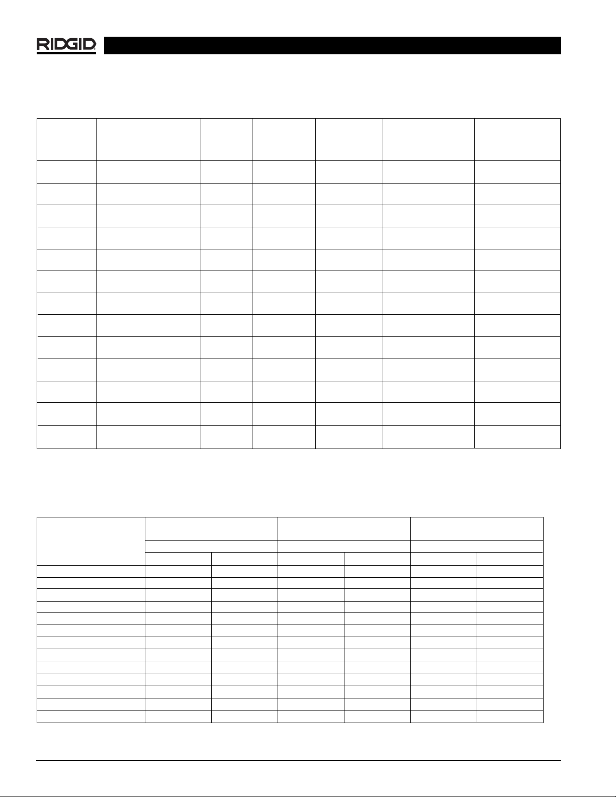
Table II. Pipe Maximum and Minimum Wall Thickness
NOTE! All Dimensions are in Inches.
CARBON STEEL OR STAINLESS STEEL
ALUMINUM PIPE OR TUBE PIPE OR TUBE PVC PIPE
Pipe Size
Wall Thickness Wall Thickness Wall Thickness
Min. Max. Min.
Max. Min. Max.
1″ .065 .133 .065 .109 .133 .133
1
1
/4″ .065 .140 .065 .140 .140 .140
1
1
/2″ .065 .145 .065 .145 .145 .200
2″ .065 .154 .065 .154 .154 .154
2
1
/2″ .083 .203 .083 .188 .203 .276
3″ .083 .216 .083 .188 .216 .300
3
1
/2″ .083 .226 .083 .188 .226 .318
4″ .083 .237 .083 .188 .237 .337
5″ .109 .258 .109 .188 .258 .258
6″ .109 .280 .109 .188 .280 .280
8″ .109 .322 .109 .188 .322 .322
10″ .134 .165 .134 .188 — —
12″ .156
.180 .156 .188 — —
CAUTION: Do not use to groove 8″ schedule 40 steel pipe harder than 150 BHN. Doing so may result in improperly formed grooves that do not meet
required specifications.
TA B C D
NOM. PIPE MIN. GASKET GROOVE GROOVE NOM.
PIPE DIAMETER WALL SEAT WIDTH DIAMETER GROOVE
SIZE O.D. TOL. THK. +.015/-.030 +.030/-.015 O.D. TOL. DEPTH (Ref. #2)
1 1.315 +.013 .065 .625 .281 1.190 +.000 .063
-.013 -.015
11/
4
1.660 +.016 .065 .625 .281 1.535 +.000 .063
-.016 -.015
1
1
/
2
1.900 +.016 .065 .625 .281 1.775 +.000 .063
-.016 -.015
2 2.375 +.024 .065 .625 .344 2.250 +.000 .063
-.016 -.015
2
1
/
2
2.875 +.030 .083 .625 .344 2.720 +.000 .078
-.018 -.015
3 3.50 +.030 .083 .625 .344 3.344 +.000 .078
-.018 -.015
3
1
/
2
4.00 +.030 .083 .625 .344 3.834 +.000 .083
-.018 -.015
4 4.50 +.035 .083 .625 .344 4.334 +.000 .083
-.020 -.015
5 5.563 +.056 .109 .625 .344 5.395 +.000 .084
-.022 -.015
6 6.625 +.050 .109 .625 .344 6.455 +.000 .085
-.024 -.015
8 8.625 +.050 .109 .750 .469 8.441 +.000 .092
-.024 -.020
10 10.75 +.060 .134 .750 .469 10.562 +.000 .094
-.025 -.025
12 12.75 +.060 .156 .750 .469 12.531 +.000 .110
-.025 -.025
Table I. Standard Roll Groove Specifications
1
NOTE! All Dimensions are in Inches.
1. As per AWWA C606-87.
2. Nominal Groove Depth is provided as a reference dimension. Do not use groove depth to determine groove acceptability.
NOTE! Fitting manufacturer’s recommendations should be followed regarding maximum allowable flare diameters.
Page 17

918 Roll Groover
Ridge Tool Company 17
Table III. Troubleshooting
PROBLEM CAUSE CORRECTION
Rolled groove too
narrow or too wide.
Rolled groove not perpendicular to pipe axis.
Pipe does not track
while grooving.
Pipe flared at groove
end.
Pipe drifts back and
forth on driving roll axis
while grooving.
Pipe rocks from side to
side.
Groover does not roll
groove in pipe.
Groove does not meet
specification.
Pipe slips on driving roll.
Incorrect size of grooving and driving rolls.
Mismatched grooving and driving rolls.
Grooving roll and/or driving roll worn.
Pipe length not straight.
Pipe end not square with pipe axis.
Pipe not level.
Groover not level.
Pipe axis not offset 1/2degree from drive roll axis.
1
/2degree offset not sufficient.
Not applying pressure to pipe.
Not using stabilizer.
Excessive weld seam.
Pipe end not square.
Pipe not level.
Operator is advancing groove roll too fast.
Pipe is too hard.
Stabilizer too tight.
Pipe length not straight.
Pipe end not square with pipe axis.
Pipe stand too close to end of pipe.
Pipe end flattened or damaged.
Hard spots in pipe material or weld seams harder
than pipe.
Grooving roll feed rate too slow.
Power drive speed exceeds 57 rpm.
Pipe support stand rollers not in correct location for
pipe size.
Pipe wall maximum thickness exceeded.
Wrong rolls.
Pipe material too hard.
Adjustment nut not set.
Maximum pipe diameter tolerance exceeded.
Mismatched grooving and driving rolls.
Grooving 8″ Sch. 40 steel pipe harder than 150
BHN.
Driving roll knurling plugged with metal or worn flat.
Grooving roll feed rate too slow.
Install correct size of grooving and driving rolls.
Match grooving and driving rolls.
Replace worn roll.
Use straight pipe.
Cut pipe end square.
Adjust stand to level pipe.
Level groover.
Offset pipe 1/2degree
(See Figs. 12 &13).
Offset pipe slightly more.
Apply pressure to pipe
(See Figs. 15 &16).
Use stabilizer.
Grind flush 2″ from end of pipe.
Cut pipe end square.
Adjust stand to level pipe.
Slow down pumping action.
(Refer to proper oper-
ating instructions.)
Replace pipe.
Adjust stabilizer.
Use straight pipe.
Cut pipe end square.
Move pipe stand in 1/4distance from end of pipe.
Cut off damaged pipe end.
Use high quality pipe of uniform hardness.
Feed grooving roll into pipe faster.
Reduce speed to 57 rpm.
Position pipe stand rollers for pipe size being used.
Check pipe capacity chart.
Install correct rolls.
Replace pipe.
Set depth.
Use correct diameter pipe.
Use correct set of rolls.
Do not groove hard pipe.
Clean or replace driving roll.
Feed grooving roll into pipe faster.
Page 18

918 Roll Groover
Ridge Tool Company18
12345678
ABCD T
Nom. Tubing Outside Gasket Groove Groove Nominal
1
Min. Max.
Size Diameter O.D. Seal Width Dia. Groove Allow. Allow.
Inches A +.03 +.00 Depth Wall Flare
Basic Tolerance +.03 –.00 –.02 Thick. Dia.
–.00
2″ 2.125 ±0.002 0.610 0.300 2.029 0.048 0.064 2.220
2
1
/2″ 2.625 ±0.002 0.610 0.300 2.525 0.050 0.065 2.720
3″ 3.125 ±0.002 0.610 0.300 3.025 0.050 0.045 3.220
4″ 4.125 ±0.002 0.610 0.300 4.019 0.053 0.058 4.220
5″ 5.125 ±0.002 0.610 0.300 5.019 0.053 0.072 5.220
6″ 6.125 ±0.002 0.610 0.300 5.999 0.063 0.083 6.220
Table IV. Copper Roll Groove Specifications
1
Nominal groove depth is provided as a reference dimension. Do not use groove depth to determine groove acceptability.
Table III. Troubleshooting (cont.)
PROBLEM CAUSE CORRECTION
Pipe raises or tends to tip
groover over backwards.
Pump not delivering oil,
cylinder does not
advance.
Pump handle operates
with “spongy” action.
Cylinder extends only
partially.
Not level.
Pump release valve open.
Low oil in reservoir.
Dirt in pump body.
Seats worn or not seating.
Too much oil in reservoir.
Air trapped in system.
Too much oil in reservoir.
Pump reservoir is low on oil.
Depth adjustment set incorrectly.
Adjust stands to level pipe.
Close release valve.
Check oil level per instructions.
Have serviced by qualified technician.
Have serviced by qualified technician.
Check oil level per instructions.
Position ram lower than pump by tipping the
machine on its side opposite the operator. Extend
and return the cylinder piston several times to
permit air to return to the pump reservoir.
Check oil level per instructions.
Fill and bleed system.
Follow depth adjustment instructions.
Page 19
918 Roll Groover
Ridge Tool Company 19
Maintenance Instructions
Make sure machine is unplugged from
power source before performing maintenance or making
any adjustments.
Hydraulic Fluid Level
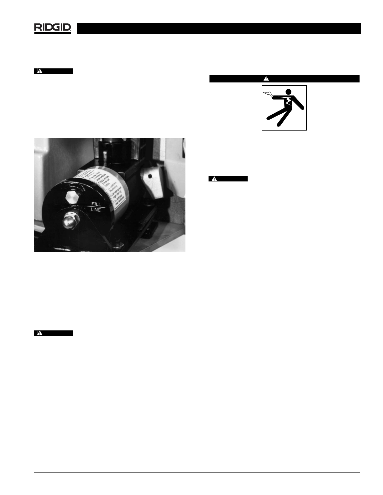
Remove the reservoir filler cap
(Figure 24)
. The oil level
should come to the fill line when the pump is resting on its
base and the ram is fully retracted. Use only high grade hydraulic oil.
Figure 24 – Reservoir Filler Cap
Lubrication
Drive shaft and Groove roll shaft bearings.
Lubricate with multi-purpose grease through fittings located on groove roll shaft and lower roll housing once a
month, and after every roll change.
Machine Storage
Motor-driven equipment must be kept indoors or well covered in rainy weather. Store the machine
in a locked area that is out of reach of children and people
unfamiliar with roll groover equipment. This machine can
cause serious injury in the hands of untrained users.
Service and Repair
WARNING
WARNING
WARNING
Service and repair work on t
formed by qualified repair personnel. Machine should
be taken to a RIDGID Independent Authorized Service
Center or returned to the factory. All repairs made by
Ridge service facilities are warranted against defects in
material and workmanship.
WARNING
cal replacement parts should be used. Failure to follow
these instructions may create a risk of serious injury.
When servicing this machine, only identi-
his Roll Groover must be per-
Page 20

Printed in U.S.A. 12/12 999-998-946.10
EC39404 REV. B
99 Washington Street
Melrose, MA 02176
Phone 781-665-1400
Toll Free 1-800-517-8431
Visit us at www.TestEquipmentDepot.com
 Loading...