

Page 1
Loop Leader PD6620 Series Loop-Powered Rate/Totalizer
Instruction Manual
Loop-Powered Totalizer
IECEx
PD6626 & PD6628 Only
• 4-20 mA Input
• Loop-Powered Flow Rate/Totalizer
• 1.5 Volt Drop (4.5 Volt Drop with Backlight)
• Display Rate & Total Simultaneously
• Loop-Powered Backlight with Red Backlight for Alarm Conditions
• NEMA 4X, IP65 Front
• -40 to 167°F (-40 to 75°C) Safe Area Operating Temperature Range
• Free PC-Based USB Programming Software
• 5-Digit Alphanumeric Top Line
• 8-Digit Alphanumeric Bottom Line
• 8-Digit Total & Grand Total Display with 13 Digits Using Top Line
• 20-Segment Bargraph with Numeric Percent Indication
• Conformal Coated PCBs for Dust & Humidity Protection
• Two Open Collector Outputs Standard
• Dual-Line Display
• 1/8 DIN Shallow Depth Case
• Optional Loop-Powered Solid-State Relays
• Optional 4-20 mA Analog Output
• UL & C-UL 61010 Listed for Electrical Safety
• UL & C-UL Listed as Intrinsically Safe and Nonincendive
• ATEX and IECEx Certified as Intrinsically Safe
PRECISION DIGITAL CORPORATION
Find Quality Products Online at: [email protected]
www.GlobalTestSupply.com
Page 2
Loop Leader PD6620 Series Loop-Powered Rate/Totalizer Instruction Manual
CAUTION: Read complete
instructions prior to installa-
tion and operation of the
meter.
WARNING: Risk of elec-
tric shock or personal
injury.
Warning!
This product is not recommended for life support applications or applications where malfunctioning could result in
personal injury or property loss. Anyone using this product
for such applications does so at his/her own risk. Precision
Digital Corporation shall not be held liable for damages resulting from such improper use.
!
Disclaimer
The information contained in this document is subject to change without notice.
Precision Digital makes no representations or warranties with respect to the contents
hereof and specifically disclaims any implied warranties of merchantability or fitness
for a particular purpose.
Limited Warranty
Precision Digital Corporation warrants this product against defects in material or
workmanship for the specified period under “Specifications” from the date of shipment from the factory. Precision Digital’s liability under this limited warranty shall not
exceed the purchase value, repair, or replacement of the defective unit.
Registered Trademarks
NORYL® and LEXAN® are registered trademarks of SABIC Innovative Plastics. All
other trademarks mentioned in this document are the property of their respective
owners.
Find Quality Products Online at: [email protected]
2
www.GlobalTestSupply.com
Page 3

Loop Leader PD6620 Series Loop-Powered Rate/Totalizer Instruction Manual
Table of Contents
Table of Contents ----------------------------------------- 3
Table of Figures ------------------------------------------- 3
Introduction ------------------------------------------------- 4
Ordering Information ------------------------------------ 5
General Purpose Instruments -------------------------------- 5
Hazardous Area Instruments ---------------------------------- 5
Enclosures ---------------------------------------------------------- 5
Specifications ---------------------------------------------- 6
Input ------------------------------------------------------------------- 6
Display ---------------------------------------------------------------- 6
General --------------------------------------------------------------- 6
Rate/Totalizer ------------------------------------------------------- 7
Batch Control ------------------------------------------------------- 7
Common Open Collector & Relay (Alarm)
Specifications ------------------------------------------------------ 7
Open Collector Output ------------------------------------------ 7
Solid State Relays ------------------------------------------------ 8
4-20 mA Transmitter Output ----------------------------------- 8
MeterView XL Programming Software --------------------- 8
General Compliance Information -------------------- 9
Electromagnetic Compatibility ------------------------------- 9
PD6626 & PD6628 Compliance Information ------ 9
Safety------------------------------------------------------------------ 9
Hazardous Area Approvals ------------------------------------ 9
Safety Information -------------------------------------- 11
Installation ------------------------------------------------ 11
Unpacking --------------------------------------------------------- 11
Panel Mounting Instructions -------------------------------- 12
Mounting Dimensions ----------------------------------------- 12
Connections ------------------------------------------------------ 13
Connectors Labeling ------------------------------------------ 13
Safe Area Current Loop (4-20 mA) Connections ------ 14
Safe Area Digital Input Connection ----------------------- 14
Safe Area 4-20 mA Output Connections ----------------- 15
Safe Area Solid State Relay Connections --------------- 15
Safe Area Open Collector Outputs ------------------------ 16
Setup and Programming ------------------------------ 17
Overview ----------------------------------------------------------- 17
Front Panel Buttons and Status LED Indicators ------ 17
MeterView XL Programming Software ------------------- 18
Display Functions & Messages----------------------------- 19
Main Menu --------------------------------------------------------- 23
Setting Numeric Values -------------------------------------- 23
Setting Up the Input Signal (INPUT) ---------------------- 24
Available Unit Classes and Units -------------------------- 25
Setting Custom Units (CUSTOM) --------------------------- 25
Scaling the 4-20 mA Input ----------------------------------- 25
Setting the Display Features (DISPLAY) ---------------- 26
Changing the Units (UNITS) -------------------------------- 26
Changing the Decimal Point Location (DEC.PT) -------- 26
Enabling or Disabling the Comma on the Bottom
Display (COMMA) ----------------------------------------------- 26
Programming the Bargraph (PD6624 & PD6628 Only)
--------------------------------------------------------------------- 26
Changing What is Displayed (TOP and BOTTOM) ----- 27
Programming the Outputs (OUTPUT) --------------------- 28
Open Collector Outputs (OPEN COLLECTR) ----------- 29
Solid State Relay Outputs (RELAY) ----------------------- 33
4-20 mA Output (4-20 mA) -------------------------------- 38
Output Control (CONTROL) ---------------------------------- 38
Advanced Features Menu (ADVANCED) ------------------ 39
Advanced Rate, Total, and Grand Total Setup (ADV
RATE, TOTAL, GTOTAL) ------------------------------------- 39
Low-Flow Cutoff (CUTOFF) ---------------------------------- 42
Noise Filter (FILTER) ---------------------------------------- 42
Enabling Password Protection (PASSWRD) ------------- 42
Programmable Function Keys User Menu (USER) ---- 43
Changing System Settings (SYSTEM) -------------------- 44
Meter Operation ------------------------------------------ 46
Front Panel Buttons Operation ----------------------------- 46
Function Keys Operation ------------------------------------- 46
Digital Input Operation ---------------------------------------- 46
Maximum/Minimum Readings ------------------------------ 46
Changing Engineering Units -------------------------------- 46
Troubleshooting ----------------------------------------- 47
Reset Meter to Factory Defaults --------------------------- 47
Determining Software Version ----------------------------- 47
Factory Default Settings ------------------------------------- 48
Troubleshooting Tips ------------------------------------------ 49
EU Declaration of Conformity for PD6622 &
PD6624 ------------------------------------------------------ 50
EU Declaration of Conformity for PD6626 &
PD6628 ------------------------------------------------------ 51
Table of Figures
Figure 1. 1/8 DIN Panel Cutout Dimensions and Panel
Mounting Details ................................................... 12
Figure 2. Meter Dimensions - Side View ....................... 12
Figure 3. Meter Dimensions - Front View ...................... 12
Figure 4. Connector Labeling for Fully Loaded Meter ... 13
Figure 5. 4-20 mA Input Connection without Backlight .. 14
Find Quality Products Online at: [email protected]
www.GlobalTestSupply.com
Figure 6. 4-20 mA Input Connection with Backlight ....... 14
Figure 7. Digital Input Connections ................................ 14
Figure 8. 4-20 mA Output Connections .......................... 15
Figure 9. Solid State Relay Connections ....................... 15
Figure 10. Open Collector Output Connections ............. 16
3
Page 4

Loop Leader PD6620 Series Loop-Powered Rate/Totalizer Instruction Manual
Introduction
These loop-powered 1/8 DIN flow rate/totalizers can be installed virtually anywhere to provide convenient
and informative display of flow rate and total from a 4-20 mA signal. One of the most convenient features
of these instruments is their ability to display both flow rate and total at the same time. For instance, flow
rate is typically displayed on the 5-digit alphanumeric top line and flow total or grand total is typically displayed on the 8-digit alphanumeric bottom line.
Both of these lines use 14-segment, alphanumeric characters for clear indication of tags, units or alarm
messages. Further enhancing the display on these instruments is a 20-segment bargraph available on
the PD6624/8 that also includes a numeric value of the percentage the bargraph represents.
These flow rate/totalizers can be installed virtually anywhere because they get their power from the 4-20
mA loop and therefore require no separate power source. And they only drop 1.5 V (4.5 V with backlight),
so they add very little burden to the loop. Additional features that allow these instruments to be installed
virtually anywhere include a NEMA 4X, IP65 front panel, an operating temperature range of -40 to 167°F
(-40 to 75°C) (for safe area products), conformally coated PCBs, and a backlit LCD that can be read in
bright sunlight or dimly lit areas. Finally, there are intrinsically safe and nonincendive versions of these
instruments that can be installed in hazardous areas.
Free, PC-based, software that connects to the meter via a micro USB cable is available for programming
and setup of the meters. In addition, the meter can be programmed, setup and operated via the four front
panel buttons. Three of these buttons can be used as function keys. In addition, a digital input is standard
and is particularly useful for remote reset of the total or to start/stop a timer/batch.
All models come equipped with two open collector outputs and are available with two solid state relays
and 4-20 mA analog output options. The open collector outputs are useful for alarm indication or sending
a pulse to indicate when a certain amount of total has been accumulated. The relays can be programmed
for alarm indication, on/off control, sample taking, or simple batch control.
4
Find Quality Products Online at: [email protected]
www.GlobalTestSupply.com
Page 5
Loop Leader PD6620 Series Loop-Powered Rate/Totalizer Instruction Manual
Loop Leader PD6622 • Standard Decimal Models – General Purpose
Model
Description
PD6622–LNN
Loop-Powered, General Purpose, No Options
PD6622–L2N
Loop-Powered, General Purpose, Two Solid State Relays
PD6622–L3N
Loop-Powered, General Purpose, 4-20 mA Analog Output
PD6622–L5N
Loop-Powered, General Purpose, Two Solid State Relays and 4-20 mA Analog Output
Loop Leader PD6624 • Bargraph Models – General Purpose
Model
Description
PD6624–LNN
Loop-Powered, General Purpose, Bargraph, No Options
PD6624–L2N
Loop-Powered, General Purpose, Bargraph, Two Solid State Relays
PD6624–L3N
Loop-Powered, General Purpose, Bargraph, 4-20 mA Analog Output
PD6624–L5N
Loop-Powered, General Purpose, Bargraph, Two Solid State Relays and 4-20 mA Analog Output
Loop Leader PD6626 • Standard Decimal Models – Hazardous Area
Model
Description
PD6626–LNN
Loop-Powered, Hazardous Area, No Options
PD6626–L2N
Loop-Powered, Hazardous Area, Two Solid State Relays
PD6626–L3N
Loop-Powered, Hazardous Area, 4-20 mA Analog Output
PD6626–L5N
Loop-Powered, Hazardous Area, Two Solid State Relays and 4-20 mA Analog Output
Loop Leader PD6628 • Bargraph Models – Hazardous Area
Model
Description
PD6628–LNN
Loop-Powered, Hazardous Area, Bargraph, No Options
PD6628–L2N
Loop-Powered, Hazardous Area, Bargraph, Two Solid State Relays
PD6628–L3N
Loop-Powered, Hazardous Area, Bargraph, 4-20 mA Analog Output
PD6628–L5N
Loop-Powered, Hazardous Area, Bargraph, Two Solid State Relays and 4-20 mA Analog Output
Enclosures
Model
Description
PDA2301
NEMA 4X Plastic Enclosure
PDA2501
Plastic NEMA 4X Enclosure
PDA2601
Stainless Steel NEMA 4X Enclosure
PDA2701
Painted Steel NEMA 4 Enclosure
PDA2801
Low-Cost Plastic NEMA 4X Enclosure
PDA3407
Internally Mount NEMA 4X Plastic Enclosure
Ordering Information
General Purpose Instruments
Hazardous Area Instruments
Note: All models come with two open collector outputs standard.
Enclosures
5
Find Quality Products Online at: [email protected]
www.GlobalTestSupply.com
Page 6

Loop Leader PD6620 Series Loop-Powered Rate/Totalizer Instruction Manual
Input
4-20 mA
Accuracy
±0.02% of span ±1 count, Square root and
programmable exponent: 10-100% FS
Voltage Drop
Without Backlight: 1.5 V maximum,
With backlight: 4.5 V maximum
Equivalent
Resistance
With backlight off: 75 Ω @ 20 mA
With backlight on: 225 Ω @ 20 mA
Input Overload
Over current protection to 1 A maximum
Over voltage protection to 30 VDC max
(between mA+ and mA-/BL-)
Temperature Drift
25 PPM/°C from -40 to 75°C ambient
Function
Linear, square root, or programmable
exponent
Low-Flow Cutoff
0.0 to 999,999.9
HART
Transparency
Analog input will not interfere with existing
HART communications on the wired 4-20 mA
signal
Display
Dual-line LCD with backlight. Both lines 14segment alphanumeric. Top: 0.7" (17.8 mm),
Bottom: 0.4" (10.2 mm). Display may be programmed to turn red and flash a user-defined
message on alarm condition.
Backlight
Powered by 4-20 mA loop. Intensity varies with
signal level
Top Line
5 digits (-9999 to 99999) or 5 characters (all
capital & most lower-case letters)
Bottom Line
8 digits (-9,999,999 to 99,999,999; separated
by commas) or 8 characters (all capital & most
lower-case letters)
Bargraph
20 segments, numeric percent indication at top
(PD6624 & PD6628 only)
Decimal Point
Up to four decimal places on top line and
up to seven decimal places on bottom line
Commas
Commas to indicate 1000s (e.g. 88,987,628)
on bottom line
Dual-Scale
Feature
The input can be displayed in different scales
on the top and bottom lines. For instance, the
top line could display the flow in GPM and the
bottom line could display that same input in
CFM.
Alarm Indication
Red backlight, flashing display, alarm symbol
(!); Symbols are not available on bargraph
models. Bargraph segment flashes on alarm.
Alarm Message
On or Off; user programmable, 8 characters
maximum. Displayed every 10 seconds for 1
second on bottom line.
Display Update
Rate
Ambient > -10°C: 1 Update/Second
Ambient = -20°C: 1 Update/2 Seconds
From -20°C to -40°C the update rate slows
down 1 second for every -2°C (e.g. at -24°C, 1
update/4 seconds).
Overrange
Top: 99999; Bottom: 99,999,999 (flashing)
Underrange
Top: -9999; Bottom: -9,999,999 (flashing)
Environmental
Operating temperature range:
-40 to 75°C for safe area products
-40 to 70°C for hazardous area products
Storage temperature range: -40 to 85°C
Relative humidity: 0 to 90% non-condensing
Printed circuit boards are conformally coated.
Programming
Method
Front panel & Free PC-based USB
programming software
Enclosure &
Materials
Enclosure: 1/8 DIN, IP65, NEMA 4X front
panel, high impact plastic, NORYL® polyphenylene ether & polystyrene blend (PPE PS)
resin, UL 94V-0, Color: gray
Gasket: Silicone Rubber
Faceplate: LEXAN® polycarbonate (PC) Film
Buttons: Silicone rubber
Noise Filter
Averages the input signal over a period of time
between 1 and 16 seconds to dampen the effects of a noisy signal that causes a jumpy display.
Filter Bypass
0.0 to 99.9% of full scale. Input signal changes
greater than bypass value are displayed immediately.
Recalibration
Recalibration is recommended at least every
12 months.
Max/Min
Display
Max/min readings reached by the process are
stored until reset by the user or until power to
the meter is turned off.
Password
There are three password types available:
Main, Total, and Grand Total. The Main password prevents access to the meter Programming Mode. Total and Grand Total passwords
prevent resetting the total and grand total, respectively.
Non-Volatile
Memory
All programmed settings and total and grand
total values are stored in non-volatile memory
for a minimum of ten years if power is lost.
Normal Mode
Rejection
64 dB at 50/60 Hz
Connections
Removable screw terminals accept 12 to 22
AWG wire
DI Digital Input
Contacts
2.1 VDC on contact. Connect normally open
contacts across DI+ to DI-
DI Digital Input
Logic Levels
Logic High: 2.4 to 30 VDC (max)
Logic Low: 0 to 0.9 VDC
Tightening Torque
Screw terminal connectors: 4.5 lb-in (0.5 Nm)
Mounting screws: 8.0 lb-in max. (0.9 Nm)
Overall
Dimensions
4.68" x 2.45" x 3.79"
(119 mm x 62 mm x 96 mm) (W x H x D)
Weight
8.7 oz (247g) with option board
Warranty
3 years parts and labor
Specifications
Except where noted all specifications apply to operation at +25°C.
Input
Display
General
Find Quality Products Online at: [email protected]
6
www.GlobalTestSupply.com
Page 7

Loop Leader PD6620 Series Loop-Powered Rate/Totalizer Instruction Manual
Rate Display
Capability
Top display: -9999 to 99999; bottom display:
-9,999,999 to 99,999,999 (with commas)
Total & Grand Total Display
Capability
Top display: -9999 to 99999; bottom display:
-9,999,999 to 99,999,999 (with commas)
13-Digit Total &
Grand Total
Capability
Up to 9,999,999,999,999 using both lines with
13-digit total feature enabled.
Total & Grand
Total Indication
On bottom display; “T” indicates total and
“GT” indicates grand total (not available on
bargraph models)
Total Decimal
Point
Up to four decimal places on top, up to seven
decimal places on bottom. Total decimal point
is independent of rate decimal point.
Totalizer
Calculates total based on rate and rate units
to display total in engineering units. A custom
factor must be programmed if using custom
defined units.
Time Base
Seconds, Minutes, Hours, Days
Totalizer Rollover
Totalizer rolls over when display exceeds
99,999,999 (9,999,999,999,999 if 13-digit limit
enabled). Relay status reflects display.
Total & Grand
Total Reset
Via front panel button or external contact closure on digital input
Total & Grand
Total Reset
Passwords
Total and grand total passwords may be entered to prevent resetting the total or grand
total unless a password is entered.
Non-Resettable
Grand Total
Grand total reset may be disabled through the
meter interface. Grand total reset may be permanently disabled by selecting YES at the
PERMLOCK menu.
Caution: Once the Grand Total has been programmed as “non-resettable” the feature cannot be disabled
Methods
Automatic or Manual, count up or count down
Manual Batch
Start
Pressing F1 function key starts the batch
Manual Batch
Pause/Stop
Pressing F3 once pauses the batch, pressing
it twice cancels the batch
Automatic
Batching
The Loop Leader can be used as an automatic batch controller where batches run continuously without operator input
Batching Relay
Operation
Single or dual-relay batching with optional
preclose for dual-stage operation
Batch Preset
Set via F2 function key anywhere between
0.0001 to 99,999 based on batch total decimal point. If batch total is assigned to bottom,
the preset can be up to 8 digits.
Batch Preclose
For two-stage batch application, a preclose
value can be set to close the main flow line.
Automatic Batch
Restart Delay
1 to 9,999 seconds. The batch will automatically restart after completion of the last batch.
High or Low
Alarm
User programmable for high or low alarm
Alarm Deadband
0-100% FS, user programmable
On & Off Time
Delay
0 to 9,999 seconds
Fail-Safe
Operation
Independent for each open collector and relay
Fail-safe on, the output is on under normal
conditions
Fail-safe off, the output is on under alarm
conditions
Alarm Operation
Automatic, automatic with manual override,
latching (manual reset anytime), latching with
reset after cleared (manual reset only after
alarm has cleared)
Alarm Indication
Red backlight, Flashing display, Alarm symbol (!); (symbols not available on bargraph
models); Bargraph segment flashes on alarm.
Alarm Message
On or Off; User programmable, 8 characters
maximum; Displayed every 10 sec for 1 sec
on bottom
Alarm
Acknowledge
Front panel ACK button or external digital input resets output and screen indication
Auto Initialization
When power is applied to the meter, open
collectors and relays will reflect the state of
the input to the meter
Timer Output
One-shot or Continuous
Off Time Delay: 1 sec to 99:59:59
(hrs:min:sec)
On Time: 1 sec to 99:59:59 (hrs:min:sec)
Stopwatch
Output turns on when started and off when
stopped
Rating
Two NPN, Isolated open collector,
5-30 VDC @ 150 mA maximum
Output
Assignment
Pulse, Alarm, Timer, Total Reset, Stopwatch
on/off, or Disable
Pulse Output
Source
Rate, Total, Grand Total, or Test Frequency
Pulse Output
Factor
0.000001 to 999,999.9
Pulse Width
0.5 ms @ 1 kHz; 500 ms @ 1 Hz;
50% duty cycle
Pulse Output
Frequency
1,000 Hz maximum
Quadrature Pulse
Output
Available for Output 2 (90° behind Output 1)
Alarm Output
Source
Assign to Rate, Total, Grand Total or Digital
Input
Rate/Totalizer
Common Open Collector & Relay (Alarm) Specifications
Batch Control
Find Quality Products Online at: [email protected]
www.GlobalTestSupply.com
Open Collector Output
7
Page 8

Loop Leader PD6620 Series Loop-Powered Rate/Totalizer Instruction Manual
Rating
250 VAC/VDC @ 1A resistive
75VA; 250VAC; 0.6A pilot duty (inductive) –
UL Code D300
25VA; 250VDC; 0.6A pilot duty (inductive) –
UL Code R300
Noise
Suppression
Metal oxide varistors across outputs
Relay
Assignment
Alarm, Sample, Timer, Batch, Stopwatch
on/off, or Disable
Alarm Output
Source
Assign to Rate, Total, Grand Total, or Digital
Input
Relay Runtime
Meter will keep track of how long each relay
has operated and display this information
Relay Cycles
Meter will keep track of how many times the
relays have cycled and display this information
Accuracy
±0.05% FS ±0.001mA
Output Source
Rate, total, re-transmit; reverse scaling
allowed
Scaling Range
1.00 to 23.0 mA
Disable
High impedance state, less than 1 mA
Calibration
Factory calibrated 4.00 to 20.00 mA
Underrange
1.0 mA, 3.5 mA, or 3.8 mA (If input < 3.5 mA);
or Off; user selectable
Overrange
20.5 mA, 20.8 mA, or 23.0 mA (If input > 20.5
mA); or Off; user selectable
Isolation
500 V input-to-output
Temperature Drift
0.5 µA/°C max from -40 to 75°C ambient
External Loop
Power Supply
7.0 VDC to 30.0 VDC maximum
Output Loop
Resistance
10-750 Ω @ 24 VDC; 10-1100 Ω @ 30 VDC
System
Requirements
Microsoft® Windows® 7 & 10
Communications
USB 2.0 (Standard USB A to Micro USB B)
Configuration
Configure meters one at a time
Configuration
Files
Generate with or without meter connected;
Save to file for later use
USB Power
Connection
Meter is powered by USB connection during
programming
Solid State Relays
4-20 mA Transmitter Output
MeterView XL Programming Software
Find Quality Products Online at: [email protected]
8
www.GlobalTestSupply.com
Page 9
Loop Leader PD6620 Series Loop-Powered Rate/Totalizer Instruction Manual
EMC Emissions
• CFR 47 FCC Part 15 Subpart B Class A emissions requirements (USA)
• AS/NZS CISPR 11:2004 Class A ISM emissions requirements (Australia)
• EN 55011:2009/A1:2010 Group 1 Class A ISM emissions requirements (EU)
• ICES-001 Issue 4 ISM emissions requirements (Canada)
EMC Emissions
and Immunity
EN 61326-1:2013 EMC requirements for Electrical equipment for measurement,
control, and laboratory use – Inductrial Use
UL & C-UL Listed
USA & Canada
UL 61010-1, 3rd Edition; CAN/CSA-C22.2 No. 61010-1-12, 3rd Edition
UL File Number
E160849
Front Panel
UL Type 4X, NEMA 4X, IP65; panel gasket provided
Low Voltage Directive
IEC 61010-1:2010 (Third Edition)
Safety requirements for electrical equipment for measurement, control, and
laboratory use
Additional Standards
UL 50E
ATEX
Certificate Number: CML 17ATEX2015X
0518
II 1G
Ex ia IIC T4 Ga
-40°C ≤ Ta ≤ 70°C
IECEx
Certificate Number: IECEx CML 17.0008X
Ex ia IIC T4 Ga
Tamb = -40°C to +70°C
UL & C-UL
UL File Number: E494837
Class I, Division 1, Groups A, B, C and D T4
Class I, Division 2, Groups A, B, C and D T4
Ex ia IIC T4 (Canada); Class I Zone 0, Zone 1,
AEx ia IIC T4 (U.S.);
Class I Zone 2, Group IIC T4 (U.S.)
PROCESS CONTROL EQUIPMENT FOR USE IN HAZARDOUS LOCATIONS
ATEX
IECEx
EN 60079-0:2012+A11:2013
EN 60079-11:2012
IEC 60079-0:2011 Ed. 6
IEC 60079-11:2011 Ed. 6
United States Standards
Canadian National Standards
UL 913, Eighth Edition
UL 60079-0, Sixth Edition
UL 60079-11, Sixth Edition
Standard No. UL 121201, 9th Edition
CSA C22.2 No. 60079-0:15
CSA C22.2 No. 60079-11:14
CAN/CSA C22.2 No. 213-17
General Compliance Information
Electromagnetic Compatibility
PD6626 & PD6628 Compliance Information
Safety
Hazardous Area Approvals
ATEX/IECEx Assessment Standards
UL Assessment Standards
Find Quality Products Online at: [email protected]
www.GlobalTestSupply.com
9
Page 10
Loop Leader PD6620 Series Loop-Powered Rate/Totalizer Instruction Manual
I.S. Equipment Entity Parameters
Required Relationship Between
Entity Parameters
I.S. Barrier Entity Parameters
V max (or Ui)
≥
Voc or Vt (or Uo)
I max (or Ii)
≥
Isc or It (or Io)
P max, Pi
≥
Po
Ci + Ccable
≤
Ca (or Co)
Li + Lcable
≤
La (or Lo)
WARNING!
AVERTISSEMENT!
EXPLOSION HAZARD – Do not disconnect equipment unless
power has been removed or the area is known to be non-hazardous
RISQUE D’EXPLOSION – NE PAS BRANCHER NI DÉBRANCHER
SOUS TENSION.
ATEX/IECEx Special Conditions for Safe Use
The following conditions relate to safe installation and/or use of the equipment.
• The permitted ambient temperature range for the PD6606/PD6608 is -40°C to 70°C.
• The equipment must be installed in an enclosure which provides a minimum degree of protection of
IP20 for the equipment connections.
• Under certain extreme circumstances, the non-metallic parts incorporated in the enclosure of this equipment may generate an ignition-capable level of electrostatic charge. Therefore, the equipment shall not
be installed in a location where the external conditions are conducive to the build-up of electrostatic
charge on such surfaces. This is particularly important if the equipment is installed in a zone 0 location.
In addition, the equipment shall only be cleaned with a damp cloth.
• The equipment loop/power port must be connected to an intrinsically safe barrier with Uo ≥ 11V.
• Entity parameters must meet the following requirements:
Ui: 30 V; Ii: 175 mA; Ci: 0 μF; Li: 0 μH; Pi: 1.0 W
• For ATEX Certification, barrier and transmitter must be ATEX Certified with Entity Parameters and must
be connected per manufacturer’s instructions.
For European Community:
The PD6606/PD6608 must be installed in accordance with the Essential Health & Safety Requirements of
Directive 2014/34/EU, the product certificates CML 17ATEX2015X and IECEx CML 17.0008X, and the
product manual.
UL/C-UL Special Conditions for Safe Use
• Associated apparatus may be in a Division 2 or Zone location if so approved.
• Under certain extreme circumstances, the non-metallic parts incorporated in the enclosure of this equip-
ment may generate an ignition-capable level of electrostatic charge. Therefore the equipment shall not
be installed in a location where the external conditions are conducive to the build-up of electrostatic
charge on such surfaces. This is particularly important if the equipment is installed in a zone 0 location.
In addition, the equipment shall only be cleaned with a damp cloth.
• The equipment shall be installed in a tool secured enclosure which provides a minimum degree of protection of IP20 for the equipment connections.
• Entity parameters must meet the following requirements:
Ui: 30 V; Ii: 175 mA; Ci: 0 μF; Li: 0 μH; Pi: 1.0 W
• For Division 2 and Zone 2 Applications: Division 2 and Zone 2 installations do NOT require the use
of an intrinsically-safe barrier or intrinsically-safe entity parameters. Class I, Division 2, Groups A, B, C,
and D T4 and Class I, Zone 2, Group IIC T4, -40C <= Ta <= +70C.
Ratings: V = 30 V dc, I = 30 mA; Relay Ratings: 250V ac/dc 1A
For North American Community:
Installation and service of this device and/or associated apparatus (barrier) should be performed only by
trained service personnel and must be installed in accordance with the manufacturer’s control drawing,
Article 504 of the National Electric Code (ANSI/NFPA 70) for installation in the United States, or Section
18 of the Canadian Electrical Code for installations in Canada.
Year of Construction
This information is contained within the serial number with the first four digits representing the year and
Find Quality Products Online at: [email protected]
month in the YYMM format.
10
www.GlobalTestSupply.com
Page 11
Loop Leader PD6620 Series Loop-Powered Rate/Totalizer Instruction Manual
CAUTION: Read complete in-
structions prior to installation
and operation of the meter.
WARNING: Risk of electric
shock or personal injury.
Warning!
• Hazardous voltages exist within enclosure. Installation and service should be performed only
by trained service personnel.
• Service requiring replacement of internal components must be performed at the factory.
• Control room equipment must not use or generate more than 250 VRMS or VDC.
• Hazardous location installation instructions for associated apparatus (barrier) must be fol-
lowed when installing this equipment.
• For safe installation of an ATEX approved transmitter in series with PD6626/PD6628 loop-
powered meters, the hazardous location installation instructions for the transmitter,
PD6626/PD6628 loop-powered meter, and associated apparatus (barrier) must be compatible.
• PD6626/PD6628 Series Loop-Powered meters do not add capacitance or inductance to the
loop under normal or fault conditions.
• Substitution of components may impair hazardous location safety.
• Equipment contains non-metallic materials and therefore special care and consideration
should be made to the performance of these materials with respect to chemicals which may
be present in a hazardous environment.
!
Safety Information
Installation
There is no need to remove the meter from its case to complete the installation, wiring, and setup of
the meter for most applications.
PD6626 and PD6628 installation must be performed in accordance with Control Drawing
LIM6600-2 in order to meet agency approval ratings.
Unpacking
Remove the meter from box. Inspect the packaging and contents for damage. Report damages, if
any, to the carrier.
If any part is missing or the meter malfunctions, please contact your supplier or the factory for assistance.
Find Quality Products Online at: [email protected]
www.GlobalTestSupply.com
11
Page 12
Loop Leader PD6620 Series Loop-Powered Rate/Totalizer Instruction Manual
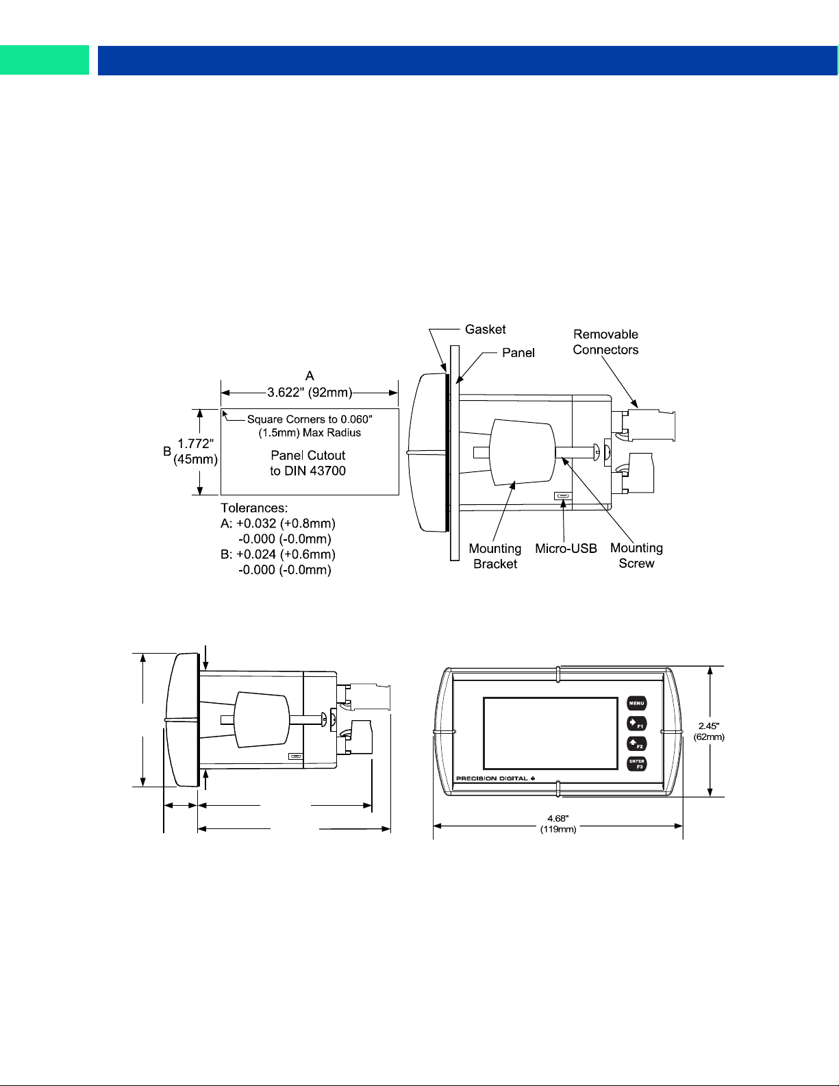
Figure 1. 1/8 DIN Panel Cutout Dimensions and Panel Mounting Details
Figure 2. Meter Dimensions - Side View
Figure 3. Meter Dimensions - Front View
1.76"
(45mm)
0.59"
(15mm)
3.2"
(81mm)
2.45"
(62mm)
3.6"
(91mm)
Panel Mounting Instructions
• Prepare a standard 1/8 DIN panel cutout – 3.622" x 1.772" (92 mm x 45 mm). Refer to Figure 1 be-
low, for more details.
• Clearance: allow at least 4.0" (102 mm) behind the panel for wiring.
• Panel thickness: 0.04" - 0.25" (1.0 mm - 6.4 mm).
Recommended minimum panel thickness to maintain Type 4X rating: 0.06" (1.5 mm) steel panel,
0.16" (4.1 mm) plastic panel.
• Remove the two mounting brackets provided with the meter (back-off the two screws so that there is ¼"
(6.4 mm) or less through the bracket. Slide the bracket toward the front of the case and remove).
• Insert meter into the panel cutout.
• Install mounting brackets and tighten the screws against the panel. To achieve a proper seal, tighten
the mounting bracket screws evenly until meter is snug to the panel along its short side. DO NOT
OVER TIGHTEN, as the rear of the panel may be damaged.
Mounting Dimensions
Find Quality Products Online at: [email protected]
12
www.GlobalTestSupply.com
Page 13
Loop Leader PD6620 Series Loop-Powered Rate/Totalizer Instruction Manual
Use copper wire with 60°C or 60/75°C insulation for all line
voltage connections. Observe all safety regulations. Electrical
wiring should be performed in accordance with all applicable
national, state, and local codes to prevent damage to the meter and ensure personnel safety.
Connections
All connections are made to removable screw terminal connectors located at the rear of the meter.
This section is only intended for PD6622 and PD6624 safe area installations.
PD6626 and PD6628 installation must be performed in accordance with Control Drawing
LIM6600-2 in order to meet agency approval ratings.
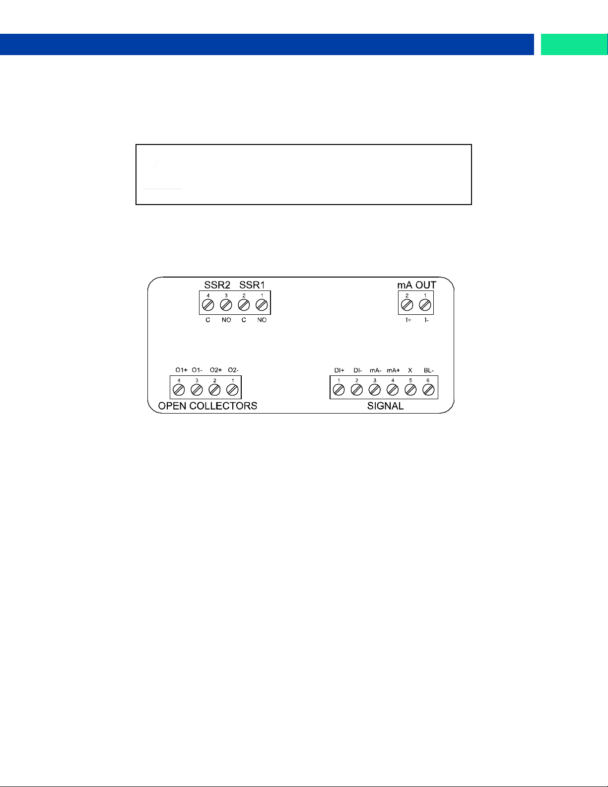
Connectors Labeling
The connectors’ label, affixed to the meter, shows the location of all connectors available with requested
configuration.
Figure 4. Connector Labeling for Fully Loaded Meter
Find Quality Products Online at: [email protected]
www.GlobalTestSupply.com
13
Page 14
Loop Leader PD6620 Series Loop-Powered Rate/Totalizer Instruction Manual
DI+ DI- mA- mA+ BL-X
DI+ DI- mA- mA+ BL-X
DI+ DI- mA- mA+ BL-X
Safe Area Current Loop (4-20 mA) Connections
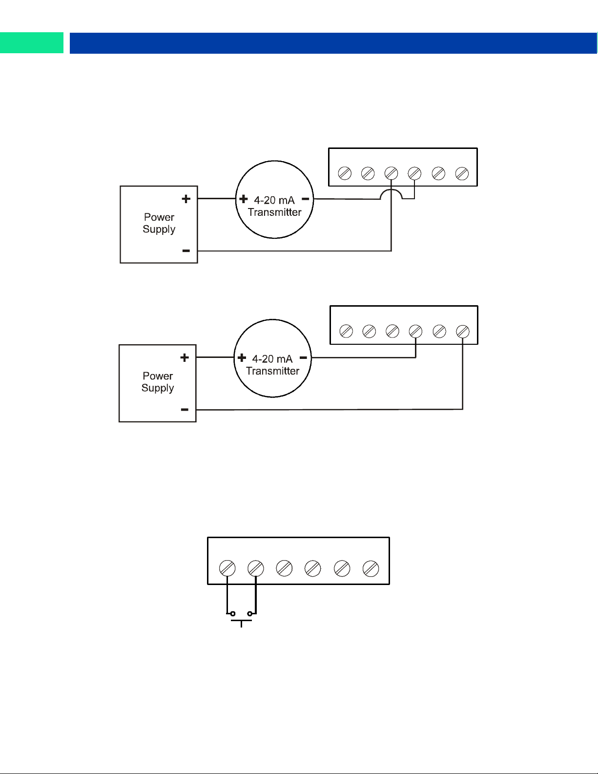
Signal connections are made to a six-terminal connector labeled SIGNAL on Figure 4. The following figures show a 4-20 mA current loop connected to the meter. The first figure shows the connection without
the backlight and the second shows the connection with the backlight (the backlight may also be disabled/enabled in the SYSTEM menu). The meter is powered by the 4-20 mA current loop.
There are no switches or jumpers to set up for the input. Setup and programming is performed through
the front panel buttons or PC-based software.
Figure 5. 4-20 mA Input Connection without Backlight
The current input is protected against current overload up to 1 amp. The display may or may not show a
fault condition depending on the nature of the overload.
Safe Area Digital Input Connection
A digital input is standard on the meter. This digital input is connected with a normally open contact
across DI+ and DI-, or with an active low signal applied to DI+ and DI-.
Figure 6. 4-20 mA Input Connection with Backlight
Figure 7. Digital Input Connections
14
Find Quality Products Online at: [email protected]
www.GlobalTestSupply.com
Page 15
Loop Leader PD6620 Series Loop-Powered Rate/Totalizer Instruction Manual
I+ I-
C NO C NO
Internal
Load Load
Safe Area 4-20 mA Output Connections
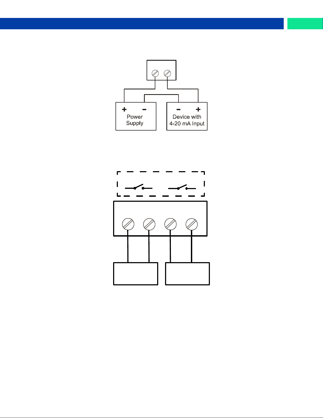
Connections for the 4-20 mA transmitter output are made to the connector terminals labeled mA OUT.
The 4-20 mA output must be powered from an external power supply.
Figure 8. 4-20 mA Output Connections
Safe Area Solid State Relay Connections
Relay connections are made to a four-terminal connector labeled SSR1 and SSR2 in Figure 4. Each relay’s C terminal is common only to the normally open (NO) contact of the corresponding relay.
Figure 9. Solid State Relay Connections
Find Quality Products Online at: [email protected]
www.GlobalTestSupply.com
15
Page 16
Loop Leader PD6620 Series Loop-Powered Rate/Totalizer Instruction Manual
O1+ O1- O2+ O2-
Safe Area Open Collector Outputs
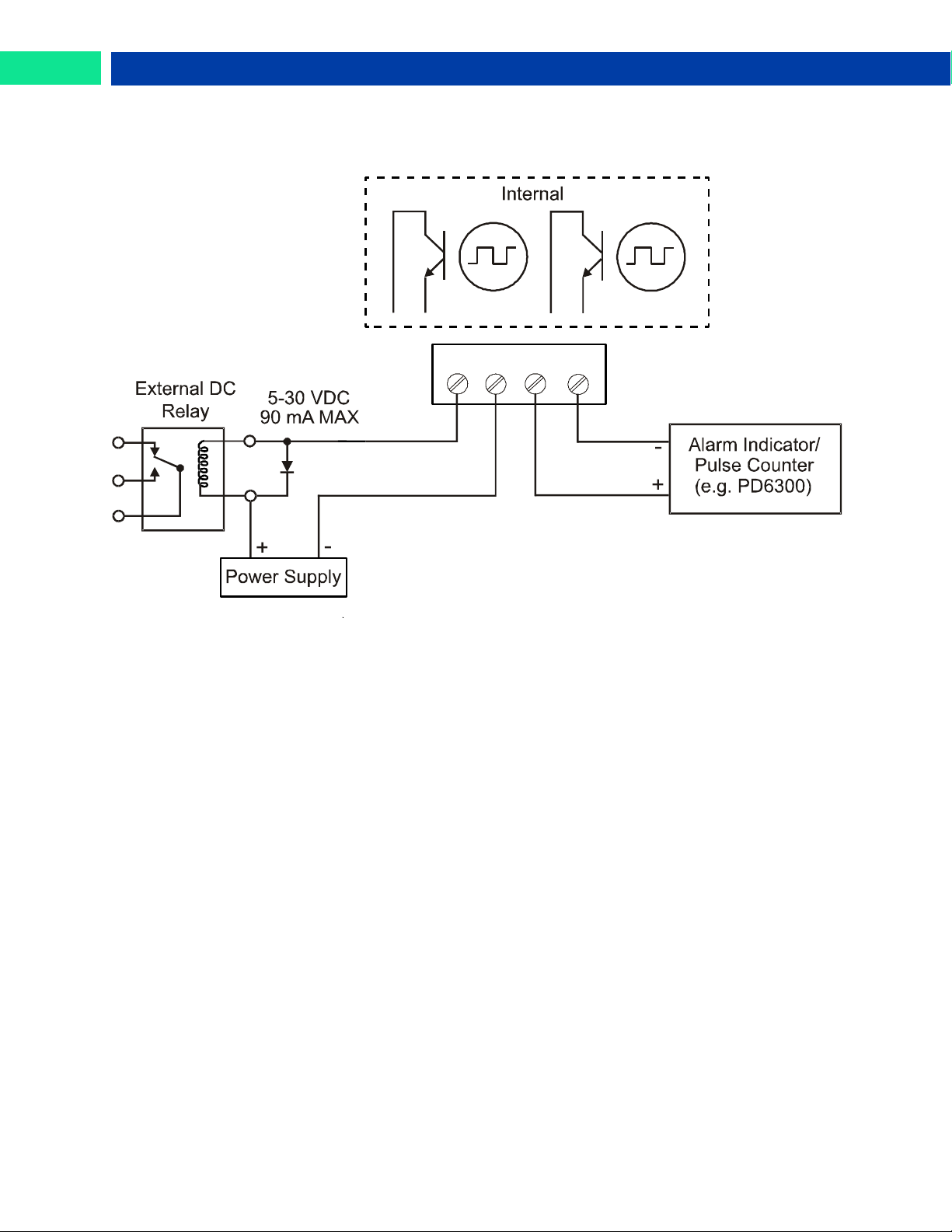
Open collector output 1 and 2 connections are made to terminals labeled O1+ and O1-, and O2+
and O2-. Connect the alarm or pulse input device as shown below.
Figure 10. Open Collector Output Connections
16
Find Quality Products Online at: [email protected]
www.GlobalTestSupply.com
Page 17
Loop Leader PD6620 Series Loop-Powered Rate/Totalizer Instruction Manual
The meter is factory calibrated prior to shipment to display 0 to 100,
which corresponds to the 4-20 mA input. The calibration equipment
is traceable to NIST standards.
Button
Symbol
Description
LCD
Status
Menu
!
Alarm Indicator
(PD6622 Only)
Right-Arrow/F1
Password Protection
Indicator
(PD6622 Only)
Up-Arrow/F2
G
Grand Total Indicator
(PD6622 Only)
Enter/F3
T
Total Indicator
(PD6622 Only)
Setup and Programming
Overview
There are no jumpers to set; setup and programming is done through the front panel buttons or PC-based
software.
The meter may be powered via the micro-USB connection located on the right side of the meter for the
purposes of programming only. The backlight will not work while the meter is powered via the USB connection.
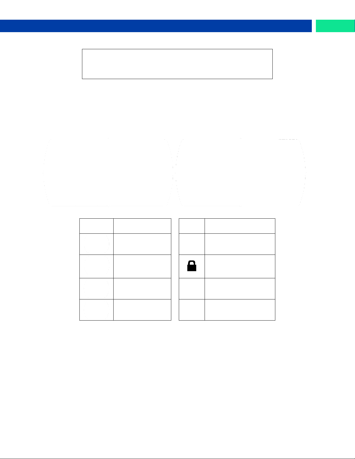
Front Panel Buttons and Status LED Indicators
PD6622/PD6626 PD6624/PD6628
• Press the Menu button to enter or exit the Programming Mode at any time.
• Press or hold the Right-Arrow button to scroll forward through the menus, select digits during nu-
meric programming, select characters during text programming, or decrement the value of a digit or
character selected with the Up-Arrow button.
• Press and hold the Right-Arrow button to zero or clear digits/characters while in data-entry mode.
• Press or hold the Up-Arrow button to scroll backwards through the menus or to increment the value
of a digit or character.
• Press the Enter button to access a menu or to accept a setting or programmed digit/character value.
Find Quality Products Online at: [email protected]
www.GlobalTestSupply.com
17
Page 18
Loop Leader PD6620 Series Loop-Powered Rate/Totalizer Instruction Manual
CAUTION!
Care should be exercised to avoid ground loops when connecting the USB to an active
loop (e.g. power supply, transmitter, loop-powered meter, etc.). It is recommended to
connect the (mA+) terminal of the meter to the (-) terminal of a two-wire transmitter.
!
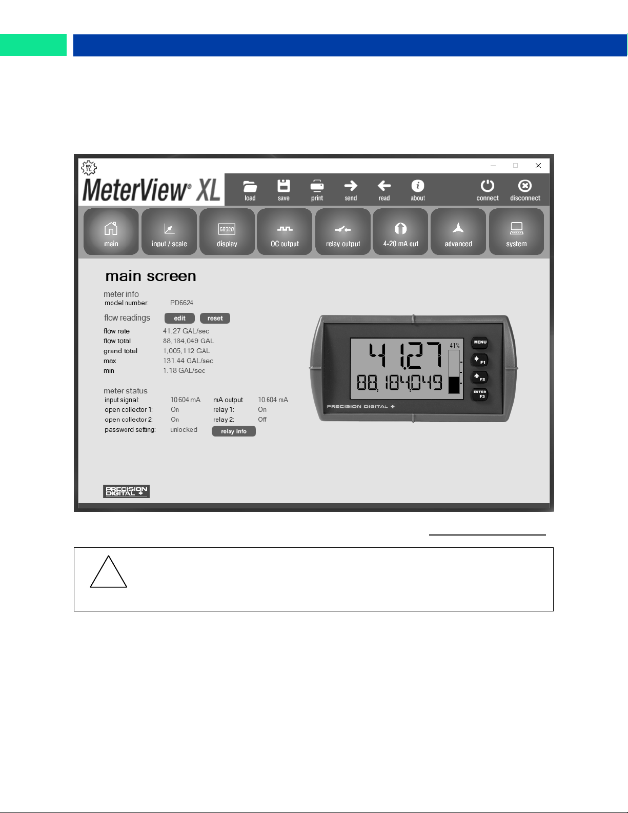
MeterView XL Programming Software
The meter can also be programmed using PC-based MeterView XL software. This software greatly simplifies the programming process and also allows the user to save configuration files for later use.
The meter connects to the PC via a provided micro-USB cable and is powered by the USB connection, so
no additional power is needed during programming.
Find Quality Products Online at: [email protected]
18
www.GlobalTestSupply.com
Page 19

Loop Leader PD6620 Series Loop-Powered Rate/Totalizer Instruction Manual
Parameter
Action/Setting Description
INPUT
Program the meter 4-20 mA input
SCALE RATE
Scale the rate input
UNITS
Select the display units
/SECOND
Units per second
/MINUTE
Units per minute
/HOUR
Units per hour
/DAY
Units per day
GAL/(T)
Gallons per time unit (T)
L/(T)
Liters per time unit (T)
IGAL/(T)
Imperial gallons per time unit (T)
M3/(T)
Cubic meters per time unit (T)
BBL/(T)
Barrels per time unit (T)
BUSH/(T)
Bushels per time unit (T)
cuYD/(T)
Cubic Yards per time unit (T)
cuFt/(T)
Cubic Feet per time unit (T)
cuIn/(T)
Cubic Inches per time unit (T)
LiBBL/(T)
Liquid barrels per time unit (T)
BBBL/(T)
Beer barrels per time unit (T)
HECtL/(T)
Hectoliter per time unit (T)
AF/(T)
Acre-Foot per time unit (T)
CUSTOM/(T)
Custom unit per time unit (T)
INPUT 1
Program input 1 value
INP 1
Enter the input 1 value
DISP 1
Program display 1 value
DSP 1
Enter the display 1 value
INPUT 2
Program input 2 value (up to 32
points)
INP 2
Enter the input 2 value
DISP 2
Program display 2 value (up to 32
points)
DSP 2
Enter the display 2 value
SAVE?
Save programmed units, input,
and display values
OUTPUT
Program the meter’s available outputs
OPEN COLLECTR
Program the meter’s open collector outputs
OUTPUT1
Open collector 1 setup
OUTPUT2
Open collector 2 setup
DISABLE
Disable the open collector
PULSE
Program the open collector for
pulse output
ALARM
Program the open collector for
alarm output
TIMER
Program the open collector as a
timer
Parameter
Action/Setting Description
TOT RST
Program the open collector for total reset
STPWATCH
Program the open collector to turn
on while the stopwatch is running
RELAY
Program the meter’s relay outputs
OUTPUT1
Relay 1 setup
OUTPUT2
Relay 2 setup
DISABLE
Disable the relay
ALARM
Program relay for alarm functionality
SAMPLE
Program relay for sample functionality
TIMER
Program relay as a timer
BATCH
Program the relay for batch control
functionality
STPWATCH
Program relay to turn on while the
stopwatch is running
INFO
View relay run time and cycle
count
4-20 mA
Program the meter’s 4-20 mA output
RATE
Transmit a value based on the rate
display
TOTAL
Transmit a value based on the total display
RETRANS
Retransmit the 4-20 mA input signal
DISABLE
Disable the 4-20 mA output
CONTROL
Program manual or automatic operation for the outputs
OC1
Open collector 1
OC2
Open collector 2
RELAY1
Relay 1
RELAY2
Relay 2
4-20 mA
4-20 mA output
AUTO
Set selected output to automatic
operation
MANUAL
Manually control selected output
operation
ADVANCED
Program the meter’s advanced
features
RATE
Advanced 4-20 mA rate input programming
FUNCTION
Select linear, square root, or programmable exponent function
LINEAR
Set meter for linear function and
select number of linearization
points
SQROOT
Set meter for square root extraction
EXPONENT
Set meter for programmable exponent and enter exponent value
Display Functions & Messages
The meter displays various functions and messages during setup, programming, and operation. The following table
shows the main menu functions and messages in the order they appear in the menu.
Find Quality Products Online at: [email protected]
www.GlobalTestSupply.com
19
Page 20

Loop Leader PD6620 Series Loop-Powered Rate/Totalizer Instruction Manual
Parameter
Action/Setting Description
SCALE.CAL
Scale or calibrate the 4-20 mA input
SCALE RATE
Scale the rate 4-20 mA input
CAL RATE
Calibrate the rate 4-20 mA input
TOTAL
Advanced total programming
COUNT
Program the totalizer functionality
LIMIT
Set the number of digits used for
the total
8-DIGIT
Eight digits max (99,999,999)
13-DIGIT
Thirteen digits max
(9,999,999,999,999) Requires top
and bottom line to display entire
number, total will roll over to zero
when it exceeds the limit.
INITIAL
Set the total to start at a specific
number
RESET
Enable or disable the ability to reset the total
ENABLE
Enable total reset (default)
DISABLE
Disable total reset
GTOTAL
Advanced grand total programming
COUNT
Program the totalizer functionality
LIMIT
Set the number of digits used for
the total
8-DIGIT
Eight digits max (99,999,999)
13-DIGIT
Thirteen digits max
(9,999,999,999,999) Requires top
and bottom line to display entire
number, total will roll over to zero
when it exceeds the limit.
INITIAL
Set the total to start at a specific
number
RESET
Enable or disable the ability to reset the grand total
ENABLE
Enable grand total reset (default)
DISABLE
Disable grand total reset
PERMLOCK
Set grand total as non-resettable
CUTOFF
Set low-flow cutoff
DISABLE
Disable low-flow cutoff
ENABLE
Enable low-flow cutoff
FILTER
Set noise filter value
1.0 SEC
1 second
2.0 SEC
2 seconds
4.0 SEC
4 seconds
8.0 SEC
8 seconds
16.0 SEC
16 seconds
OFF
Turn filter off
BYPASS
Set filter bypass (0.0 to 99.9% FS)
PASSWRD
Set a password for the meter
MAIN
Program the main meter password
TOTAL
Program the total reset password
Parameter
Action/Setting Description
GTOTAL
Program the grand total reset
password
USER
Assign function keys and digital input
F1
Assign F1 function key
F2
Assign F2 function key
F3
Assign F3 function key
DI
Assign digital input
DISP FN
Set the function key or digital input
to display a value
DISPLAY
Cycle max, min, rate, total, and
grand total
D RATE
Display the rate
D TOTAL
Display the total
DISP GT
Display the grand total
PCT.RATE
Display the rate’s percentage of
max (20 mA)
D UNITS
Display the rate, total, and grand
total units
D TAG
Display the tags
DISPMIN
Display the minimum rate value
DISPMAX
Display the maximum rate value
MIN MAX
Display the minimum and maximum rate value
D mA IN
Display the current mA input value
D mAOUT
Display the current mA output
value
MENU FN
Set the function key or digital input
to access a menu
RLYINFO
Go to relay information menu
(INFO)
MANCTRL
Go to output control menu (CONTROL)
TIMR OC1
Open collector 1 timer
TIMR OC2
Open collector 2 timer
TIMER R1
Relay 1 timer
TIMER R2
Relay 2 timer
TIMER.FN
Set the function key or digital input
to start or stop a timer
STRT.ALL
Start all timers
STOP.ALL
Stop all timers
S.STP.ALL
Start or stop all timers
OC1
Start/stop open collector 1 timer
OC2
Start/stop open collector 2 timer
RLY1
Start/stop relay 1 timer
RLY2
Start/stop relay 2 timer
START
Start the selected timer output
STOP
Stop the selected timer output
STR-STP
Start or stop the selected timer
output
BATCH.FN
Set the function key or digital input
to batch control
Find Quality Products Online at: [email protected]
20
www.GlobalTestSupply.com
Page 21

Loop Leader PD6620 Series Loop-Powered Rate/Totalizer Instruction Manual
Parameter
Action/Setting Description
START
Start a batch
STOP
Stop a batch
STR-STP
Start or stop a batch
PRESET
Preset batch amount
ALARM.FN
Set the function key or digital input
to acknowledge an alarm or access set points
ACK
Acknowledge all active alarms
SETPOINT
Access all output set points
SETPT.OC1
Access open collector 1 set point
SETPT.OC2
Access open collector 2 set point
SETPT.R1
Access relay 1 set point
SETPT.R2
Access relay 2 set point
SWATCH.FN
Set the function key or digital input
to activate stopwatch
START
Start the stopwatch
STOP
Pause/Stop the stopwatch
STR-STP
Start or stop the stopwatch
HOLD FN
Set the function key or digital input
to hold an output
HOLD.OUT
Hold all outputs
HLD.UNHLD
Hold or un-hold all outputs
OC1+2
Hold/un-hold open collector outputs
RLY1+2
Hold/un-hold relay outputs
mAOUT
Hold/un-hold 4-20 mA output
HOLD
Hold selected output
HLD.UNHLD
Hold or un-hold selected output
DISABLE
Disable the function key or digital
input
RST FN
Set the function key or digital input
to reset a value
RESET
Reset min, max, or max/min PV
value
R MIN.MAX
Reset max and min PV value
RST T
Reset the total
RST GT
Reset the grand total
RST T.GT
Reset the total and grand total
HINT
Display hint text on first key press
and execute action on second key
press
OFF
Turn the hint function off
ON
Turn the hint function on
SYSTEM
Program system settings
AOUTCAL
Calibrate the analog output
DEFAULT
Reset meter to factory defaults
TOTAL
Enable or disable the totalizer
ENABLE
Enable the totalizer (Default)
DISABLE
Disable the totalizer (see PD6602
manual)
BACKLITE
Enable or disable the display backlight
Parameter
Action/Setting Description
ENABLE
Enable the backlight (default)
DISABLE
Disable the backlight
INFO
View meter software, version, and
model, and change the meter identifier tag
SFT
The software ID number
VER
The software version
MODEL
The meter hardware model number
ID.TAG
The meter identifier tag
Press Enter to edit tag
ICAL
Internal calibration used for scaling
DISPLAY
Program the meter’s display
UNITS
Change the display units within the
selected unit class
DEC.PT
Change the decimal point location
RATE
Program the rate decimal point
TOTAL
Program the total decimal point
GTOTAL
Program the grand total decimal
point
COMMA
Enable or disable the use of a
comma to separate the thousands
place on the bottom display
ENABLE
Enable comma (default)
DISABLE
Disable comma
TOP
Set what to display on the top line
RATE
Display the rate
RATE+U
Display the rate and its units alternating
TOTAL
Display the total
TOTAL+U
Display the total and its units alternating
GTOTAL
Display the grand total
TAG
Display the tag
UNITS
Display the units
PRESET
Display the preset value
STPWATCH
Display the stopwatch
TIMR OC1
Display open collector 1 timer
TIMR OC2
Display open collector 2 timer
TIMER R1
Display relay 1 timer
TIMER R2
Display relay 2 timer
MIN
Display minimum value
MAX
Display maximum value
MIN MAX
Display alternating min and max
BOTTOM
Set what to display on the bottom
line
TOTAL
Display the total
TOTAL+U
Display the total and its units alternating
TOT+TAG
Display the total and its tag alternating
T+U+RU
Display the total, its units, and the
rate units alternating
Find Quality Products Online at: [email protected]
www.GlobalTestSupply.com
21
Page 22

Loop Leader PD6620 Series Loop-Powered Rate/Totalizer Instruction Manual
Parameter
Action/Setting Description
GTOTAL
Display the grand total
GT+UNITS
Display the grand total and its
units alternating
GT+TAG
Display the grand total and its tag
alternating
GT+U+RU
Display the grand total, units, and
rate units alternating
RATE
Display the rate
RATE+TU
Display the rate and the total’s
units alternating
RATE+U
Display the rate and its units alternating
RATE+TAG
Display the rate and its tag alternating
R UNITS
Display the rate units
T UNITS
Display the total units
TAG
Display the tag
Parameter
Action/Setting Description
UNITS
Display the units
PRESET
Display the preset value
STPWATCH
Display the stopwatch
TIMR OC1
Display open collector 1 timer
TIMR OC2
Display open collector 2 timer
TIMER R1
Display relay 1 timer
TIMER R2
Display relay 2 timer
TAG+RU
Display the tag and rate units alternating
TAG+TU
Display the tag and total units alternating
OFF
Disable the bottom display
R PCT
Display the rate’s percentage of
full scale
ma IN
Display the current mA input value
mA OUT
Display the current mA output
value
Find Quality Products Online at: [email protected]
22
www.GlobalTestSupply.com
Page 23
Loop Leader PD6620 Series Loop-Powered Rate/Totalizer Instruction Manual
DSP 1
+00,000.00
DSP 1
00,000.00
Select
Digit to
Change
DSP 1
00,050.00
Increment
Selected
Digit
SCALE
INPUT 2
Accept
Setting
52.86
38,418.2
SETUP
INPUT
SETUP
OUTPUT
SETUP
ADVANCED
SETUP
DISPLAY
OPEN
COLLECTR
ADV
RATE
DSPLY
UNITS
OUT
RELAY
OUT
4-20 mA
OUT
CONTROL
CUTOFF
FILTER
PASSWRD
USER
SYSTEM
DSPLY
DEC.PT
DSPLY
COMMA
DSPLY
TOP
DSPLY
DOTTOM
SCALE
UNITS
SCALE
INPUT 1
SCALE
DISP 1
SCALE
INPUT 2
SCALE
DISP 2
SAVE?
ADV
TOTAL
ADV
GTOTAL
Run Mode
DSPLY
BARGRAPH
*PD6624/8
Only
*
Main Menu
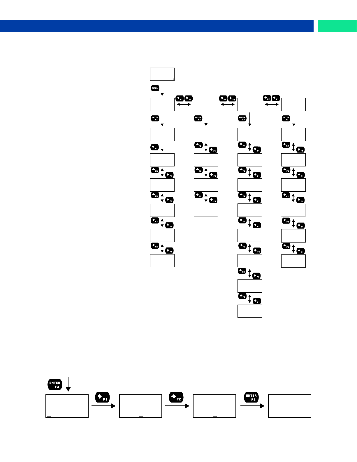
The main menu consists of all the meter’s programmable functions: Input, Output, Advanced, and Display.
• Press Menu button to enter Programming Mode then press the
Right-Arrow button to move forward through the menu and the
Up-Arrow button to move back.
• Press Menu at any time to go back
one level or press & hold to exit
and return to Run Mode. Changes
made to settings prior to pressing
Enter are not saved.
• Changes to the settings are saved
to memory only after pressing En-
ter/F3 to confirm the setting or
pressing Enter/F3 at the SAVE?
screen when available.
Setting Numeric Values
The numeric values are set using the Right and Up-Arrow buttons. Press Right-Arrow to select next
digit and Up-Arrow to increment digit value. The selected digit will flash.
Press and hold Up-Arrow to auto-increment the display value. If you have made a mistake or would like
to enter a new value, select the left-most digit and press and hold the Right-Arrow button until all digits
reset to zero.
Press the Enter button at any time to accept a setting or Menu button to exit without saving changes.
Note: the underscore in the graphic below is provided to show which digit would be flashing.
Find Quality Products Online at: [email protected]
www.GlobalTestSupply.com
23
Page 24
Loop Leader PD6620 Series Loop-Powered Rate/Totalizer Instruction Manual
SETUP
INPUT
SCALE
UNITS
SCALE
INPUT 1
SCALE
DISP 1
TIME
/SECOND
UNIT
GAL/S
/SECOND
/MINUTE
/HOUR
/DAY
Rate Time
Bases
INP 1
04.000
INP 1
mA
Flashes Units
Momentarily
DSP 1
+00,000.00
SCALE
INPUT 2
INP 2
20.000
SCALE
DISP 2
DSP 2
+00,100.00
SAVE? SETUP
INPUT
GAL/(T)
L/(T)
IGAL/(T)
Rate Units
M3/(T)
BBL/(T)
BUSH/(T)
cuYD/(T)
cuFt/(T)
cuIn/(T)
LiBBL/(T)
BBBL/(T)
HECtL/(T)
AF/(T)
CUSTM/(T)
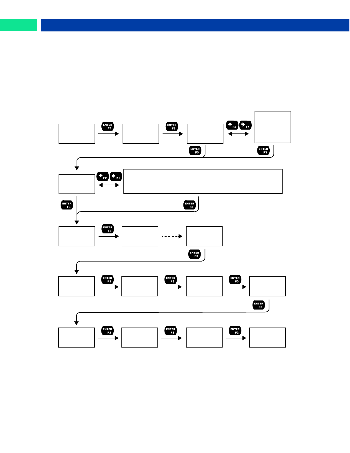
Setting Up the Input Signal (INPUT)
It is very important to read the following information before proceeding to program the meter:
• The meter is factory calibrated prior to shipment to display 0-100 gal/s, which corresponds to the 4-20
mA input. The calibration equipment is traceable to NIST standards.
• A calibrated signal source is not needed to scale the meter.
Enter the Input menu to scale the meter to display the 4-20 mA input. The input is capable of accepting
any signal from 4 to 20 mA.
Find Quality Products Online at: [email protected]
24
www.GlobalTestSupply.com
Page 25
Loop Leader PD6620 Series Loop-Powered Rate/Totalizer Instruction Manual
Rate Time Bases (TIME)
/SECOND
Units per second
/MINUTE
Units per minute
/HOUR
Units per hour
/DAY
Units per day
Rate Units (RATE)
GAL/(T)
Gallons per time unit (T)
L/(T)
Liters per time unit (T)
IGAL/(T)
Imperial gallons per time unit (T)
M3/(T)
Cubic meters per time unit (T)
BBL/(T)
Barrels per time unit (T)
BUSH/(T)
Bushels per time unit (T)
cuYD/(T)
Cubic Yards per time unit (T)
cuFt/(T)
Cubic Feet per time unit (T)
cuIn/(T)
Cubic Inches per time unit (T)
LiBBL/(T)
Liquid barrels per time unit (T)
BBBL/(T)
Beer barrels per time unit (T)
HECtL/(T)
Hectoliter per time unit (T)
AF/(T)
Acre-Foot per time unit (T)
CUSTOM/
Custom unit per time unit (T)
C.UNIT
ABC
C.UNIT
ABC
Select
Character
to Change
C.UNIT
ACC
Increment
Selected
Character
C.UNIT
ABC
Decrement
Selected
Character
C.UNIT
ABC
Accept
Character
Change
Accept
Custom Unit
Name
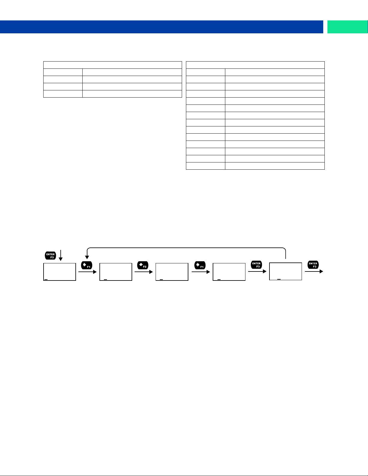
Available Unit Classes and Units
The meter has preprogrammed rate and time base units. The following are available units to choose from:
Note: for access to additional predefined units, you must disable the totalizer. See Disabling the Totalizer
(TOTAL) on page 44.
Setting Custom Units (CUSTOM)
When the desired unit of measure is not available, a custom unit may be programmed. Select the
CUSTOM menu in order to enter a custom unit name.
Text values are set using the Right and Up-Arrow buttons. Press Right-Arrow to select next character
and Up-Arrow to increment character value. The selected character will flash. Press and hold the Up or
Right-Arrow buttons to auto-increment or decrement the character. Press Enter to accept the character.
Notes:
• Press and hold the Right Arrow while no character is being edited to erase all characters to the
right of the flashing character
• Press and hold Up or Right Arrow to auto-increment or decrement a selected character.
• All text values, including tags and alarm messages, are set in a similar fashion.
Scaling the 4-20 mA Input
The 4-20 mA input can be scaled to the appropriate values for a given application. The 4-mA input (input
1) should have a corresponding display value (display 1) which represents the low end of the process
value range being measured by the transmitter. Likewise, the 20-mA input (input 2) should have a display
value (display 2) which represents the high end of the process value range.
For example: If the meter is setup to accept a 4-20 mA input and display the flow of a pipe whose rate of
flow is between 0 and 100 gal/s, the transmitter would send a 4-mA signal when there is zero flow and a
20-mA signal when there is maximum flow. The meter should be programmed to interpret these inputs on
a display range of 0-100, so that at 4-mA the meter will display 0 and at 20-mA the meter will display 100.
Processes which require a non-linear scale can be accommodated using the linear (LINEAR), exponent
(EXPONENT), and square root (SQROOT) functions available in the Advanced menu. See Signal Input
Conditioning Functions (FUNCTION) on page 40.
A signal source is not needed to scale the meter; simply program the inputs and corresponding display
values.
Find Quality Products Online at: [email protected]
www.GlobalTestSupply.com
25
Page 26
Loop Leader PD6620 Series Loop-Powered Rate/Totalizer Instruction Manual
DEC.PT
222222.22
DEC.PT
1111111.1
Move Decimal
to the Right
DEC.PT
222222.22
DSPLY
COMMA
Accept
Decimal
Location
DEC.PT
RATE
Move Decimal
to the Left
DSPLY
BARGRAPH
GRAPH
RATE
GRAPH
TOTAL
GRAPH
OFF
GRAPH
RATE PCT
SETUP
DISPLAY
DSPLY
UNITS
DSPLY
DEC.PT
DSPLY
COMMA
DSPLY
TOP
DSPLY
DOTTOM
DSPLY
BARGRAPH
PD6624/8 Only
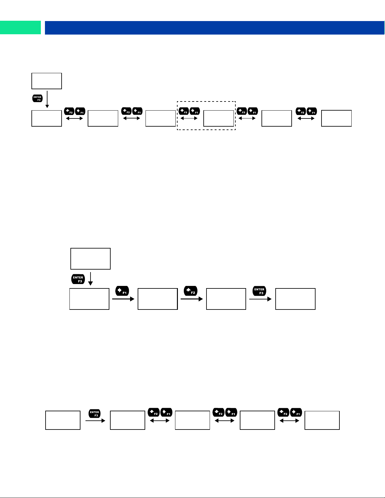
Setting the Display Features (DISPLAY)
The meter’s display functions may be programmed using the Display menu. This menu consists of the
following submenus: Units, Decimal Point, Comma, Bargraph (PD6624/8 Only), Top, and Bottom.
Changing the Units (UNITS)
It is possible to change the display units without the need to re-scale the meter. When selecting a new
unit from within the DISPLAY menu (e.g. changing from gallons/sec. (GAL/s) to liters/sec. (L/s)), the
meter will automatically convert the display values to display the new unit. Enter the UNITS menu, select
a new unit of measure from the list of predefined units, and press the Enter button. If entering a custom
unit (CUSTM), a custom conversion factor will need to be entered.
Changing the Decimal Point Location (DEC.PT)
The decimal point may be set with up to seven decimal places or with no decimal point at all.
Pressing the Right Arrow moves the decimal point one place to the right until no decimal point is displayed, and then it moves to the leftmost position. Pressing the Up-Arrow moves the decimal point one
place to the left.
The decimal point location is set independently for the rate, total and grand total.
Enabling or Disabling the Comma on the Bottom Display (COMMA)
The bottom display is set to show a comma separating the thousands and millions place by default if a
numeric value is being displayed. This feature can be disabled or enabled using the Comma menu.
Programming the Bargraph (PD6624 & PD6628 Only)
The PD6624 and PD6628 come equipped with a bargraph display for applications where a visual representation of the rate or total’s percentage of full scale is desirable. This feature can be changed to represent either rate, a percentage of the rate, or total, or disabled, using the Bargraph menu (BARGRAPH). If
the bargraph is set to represent total, the total full scale will need to be set.
Find Quality Products Online at: [email protected]
26
www.GlobalTestSupply.com
Page 27
Loop Leader PD6620 Series Loop-Powered Rate/Totalizer Instruction Manual
DSPLY
TOP
DSPLY
BOTTOM
DSPLY
RATE
DSPLY
TOTAL
TOTAL+U
TOT+TAG
T+U+TAG
GTOTAL
GT+UNITS
GT+TAG
RATE
GT+U+RU
RATE+U
RATE+TU
RATE+TAG
R UNITS
T UNITS
TAG
UNITS
PRESET TAG+TU
TAG+RU
R PCT
OFF
mA OUT
mA IN
Top Line Display Parameters
RATE+U
TOTAL
TOTAL+U
TAG
PRESET
UNITS
TIMR OC1
STPWATCH
TIMR OC2
TIMER R1
TIMER R2
MIN
MIN MAX
MAX
TIMR OC1
STPWATCH
TIMR OC2
TIMER R1
TIMER R2
Bottom Line Display Parameters
OFF
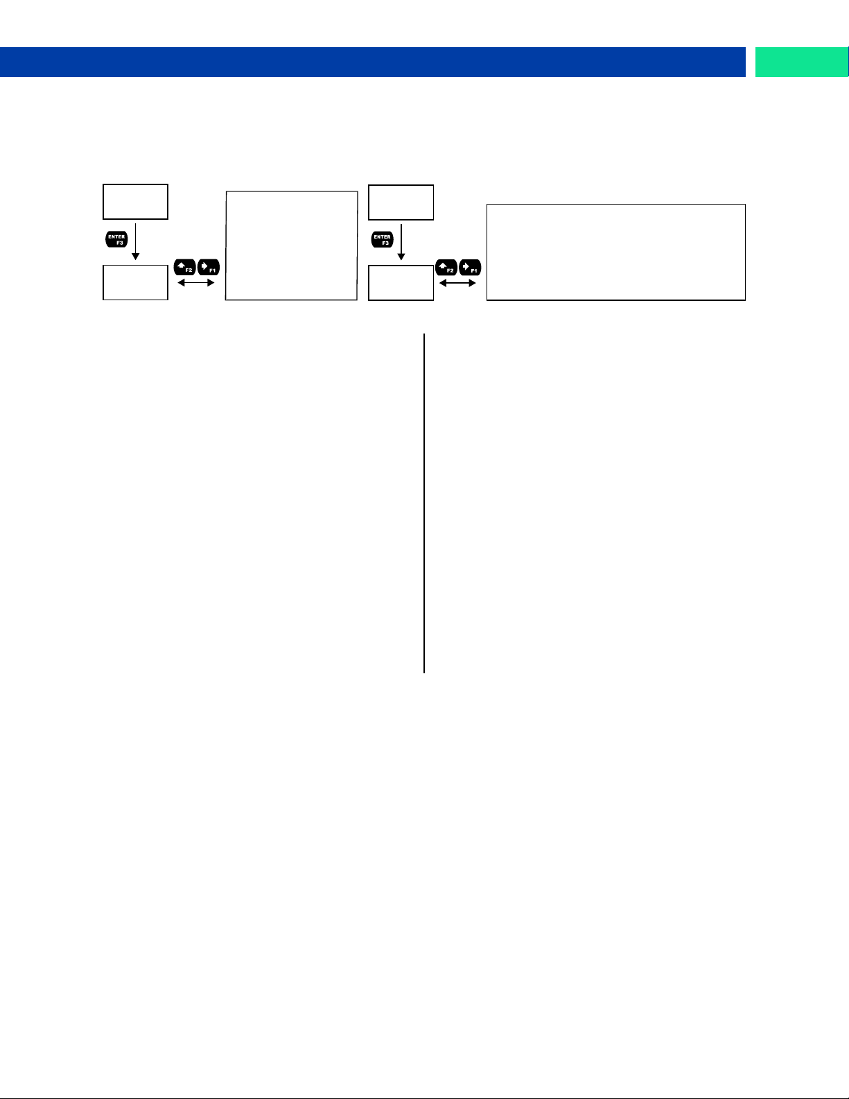
Changing What is Displayed (TOP and BOTTOM)
The two display lines (Top and Bottom) can be programmed to display different values. Use the Top and
Bottom menus to make these changes. If PV2 is enabled, additional options will be available for display-
ing the second PV on the bottom display.
The top display (TOP) can display:
• Rate
• Rate and its units alternating
• Total
• Total and its units alternating
• Grand Total
• Tag
• Units
• Preset batch value
• Stopwatch
• Open Collector 1 or 2 Timer
• Relay 1 or 2 Timer
• Minimum Value, Maximum Value, or Both
• Off (Blank)
The bottom display (BOTTOM) can display:
• Total (with units or tag alternating)
• Total, its units, and the rate units alternating
• Grand total (with units or tag alternating)
• Grand total, units, and rate units alternating
• Rate (with units or tag alternating)
• Rate and the total’s units alternating
• Rate or total units
• Tag
• Units
• Preset batch value
• Stopwatch
• Open Collector 1 or 2 Timer
• Relay 1 or 2 Timer
• Tag and rate units alternating
• Tag and total units alternating
• Off (Blank)
• Rate's percentage of max scale
• mA input value
• mA output value
Find Quality Products Online at: [email protected]
www.GlobalTestSupply.com
27
Page 28
Loop Leader PD6620 Series Loop-Powered Rate/Totalizer Instruction Manual
SETUP
OUTPUT
OPEN
COLLECTR
OUT
RELAY
OUT
4-20 mA
OUT
CONTROL
OC.OUT
OUTPUT1
OC.OUT
OUTPUT2
RELAY
OUTPUT1
RELAY
OUTPUT2
RELAY
INFO
4-20
RATE
4-20
RETRANS
4-20
DISABLE
CTRL
OC1
CTRL
OC2
CTRL
RELAY1
CTRL
RELAY2
CTRL
4-20 mA
4-20
TOTAL
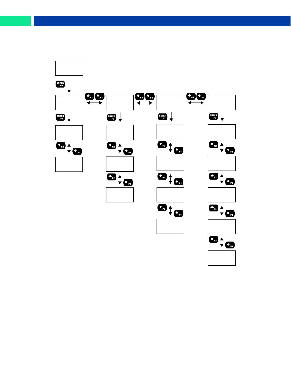
Programming the Outputs (OUTPUT)
Depending on the purchased model, the meter may be available with two open collector outputs, two
solid state relays, and one 4-20 mA output. The Output menu will only show options for the available outputs. See Ordering Information on page 5 for details.
28
Find Quality Products Online at: [email protected]
www.GlobalTestSupply.com
Page 29
Loop Leader PD6620 Series Loop-Powered Rate/Totalizer Instruction Manual
SETUP
OUTPUT
OPEN
COLLECTR
OC.OUT
OUTPUT1
OC.OUT
OUTPUT2
OUT 1
PULSE
PULSE
RATE
PULSE
QUAD
*Available
for output
2 only.
*
OUT 1
ALARM
OUT 1
TIMER
OUT 1
STPWATCH
ALARM
RATE
ALARM
D.INPUT
TIMER
OFF.DLAY
TIMER
ON TIME
TIMER
MODE
TIMER
START
MODE
CONT
MODE
ONE.SHOT
PULSE
TEST
OUT 1
TOT RST
TIME
0000 SEC
PULSE
TOTAL
PULSE
GTOTAL
ALARM
TOTAL
ALARM
GTOTAL
OUT 1
DISABLE
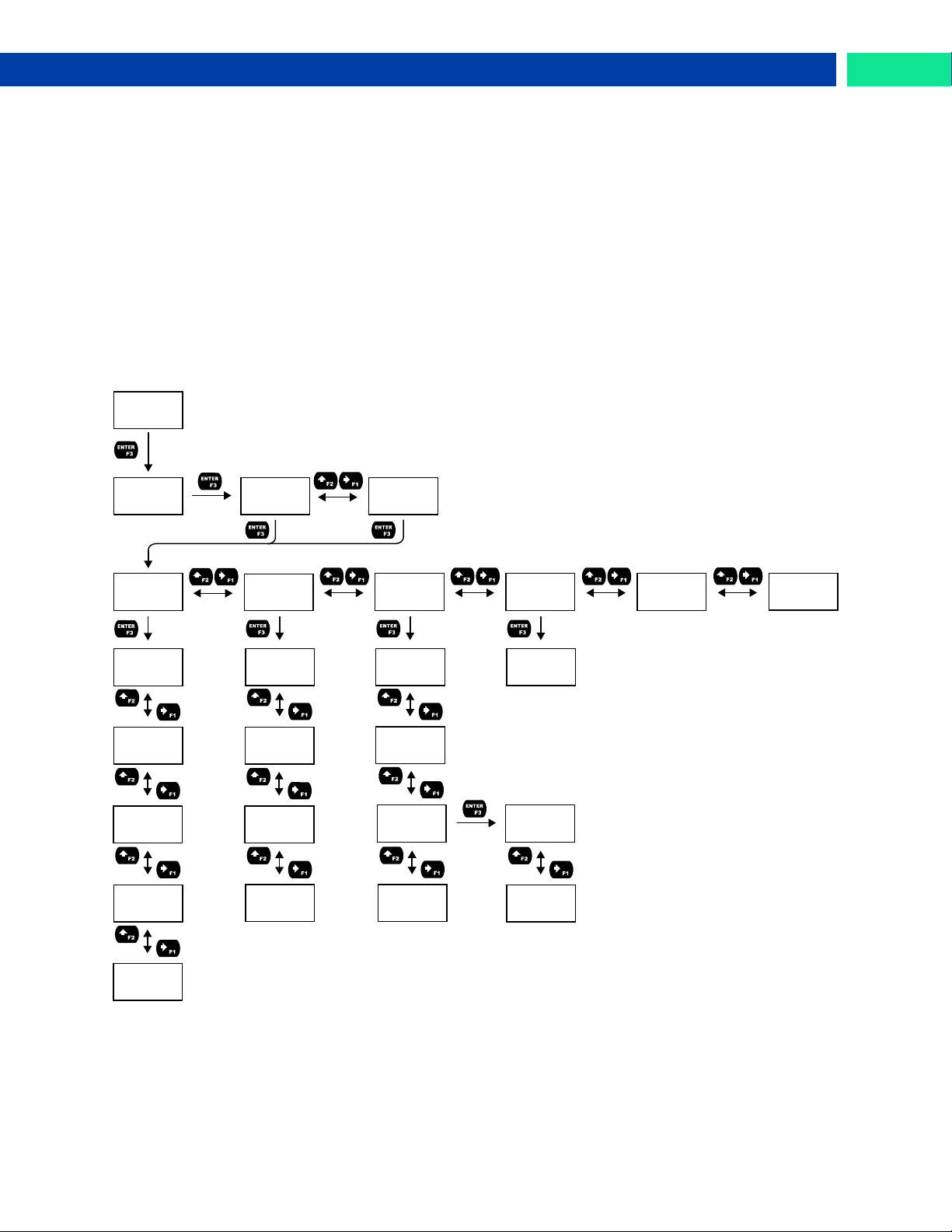
Open Collector Outputs (OPEN COLLECTR)
The meter is equipped with two NPN open collector outputs that may be set up for pulse outputs, alarms,
timed pulses, total reset, or disabled.
Pulse outputs can be set to transmit the rate, total, or grand total. Output 2 may be used to generate a
quadrature output based on the other open collector output. An output test mode is also selectable to
generate pulses at a constant programmable frequency.
Alarms are available based on the PV value or the digital input. The alarm status will show on the display
even if the output is not wired.
A timer output (TIMER) turns the open collector on and off at the specified time intervals. The timer can
be set as single-shot or continuous timer.
A total reset output generates a pulse whenever the total is reset, regardless of the reset method used.
The On time is programmable between 0 and 9,999 seconds.
The stopwatch output (STPWATCH) allows the open collector to be manually activated by starting the
stopwatch. The stopwatch count can be displayed on the top or bottom line.
The output may be disabled by selecting DISABLE.
Find Quality Products Online at: [email protected]
www.GlobalTestSupply.com
29
Page 30
Loop Leader PD6620 Series Loop-Powered Rate/Totalizer Instruction Manual
OUT 1
PULSE
PULSE
TEST
PULSE
QUAD
*Available
for output
2 only.
*
FACTR
GAL/S
Flashes
Units
FACTR
+0,001.000
FREQ
100.0
PULSE
RATE
PULSE
TOTAL
PULSE
GTOTAL
KFACT
P/GAL
Flashes
Units
KFACT
001.0000
Pulse (PULSE)
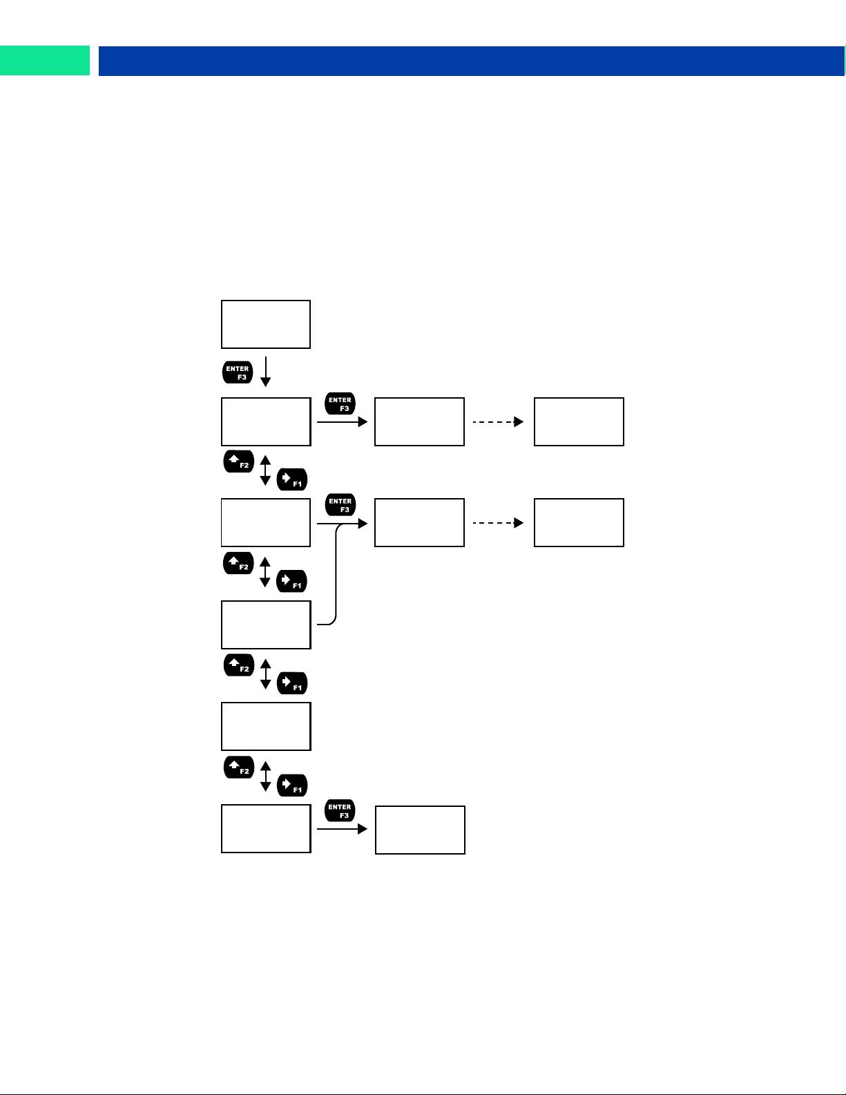
Pulse outputs may be assigned to output the rate, total, or grand total at a programmable factor. If the
output is assigned to rate, the factor is a multiplier that determines the number of pulses generated based
on the rate. For example, if the meter display shows 100 gallons/second and the factor is set to 2, the
number of pulses generated per second would be 200. If the output is assigned to total or grand total, the
k-factor corresponds to the number of pulses generated per unit of measure. For example, if the k-factor
is 0.001 and the units are gallons, one pulse will be generated for every 1,000 gallons. The maximum frequency is 1,000 Hz.
Setting output 2 to quadrature will duplicate the other open collector output, but lag by 90 degrees out of
phase. The other output should be programmed as desired for the quadrature output function and must
be a pulse (PULSE) output selection. The quadrature maximum frequency for both outputs is 500 Hz.
The TEST option will output a fixed number of pulses per second based on the FREQ value entered.
Find Quality Products Online at: [email protected]
30
www.GlobalTestSupply.com
Page 31
Loop Leader PD6620 Series Loop-Powered Rate/Totalizer Instruction Manual
OUT 1
ALARM
ALARM
D.INPUT
ALARM
ACTION
ACTN
AUTO
ACTN
AUTO.MAN
ACTN
LATCH
ACTN
L-CLEAR
SET
+00,040.00
SET
GAL
Flashes
Units
ALARM
RESET
ALARM
SET
RESET
+00,030.00
ALARM
DELAY
DELAY
ON
TIME
0000 SEC
DELAY
OFF
TIME
0000 SEC
ALARM
FAILSAFE
Rate, Total, GTotal Alarm Only
FSAFE
OFF
ALARM
DISPLAY
RED
ON
FLASH
ON
ALARM
GTOTAL
Rate Alarm Only
Rate, Total, Gr.
ALARM
RATE
ALARM
TOTAL
MSG
ON
MSG
ALARM 1
Total Alarm Only
Alarm (ALARM)
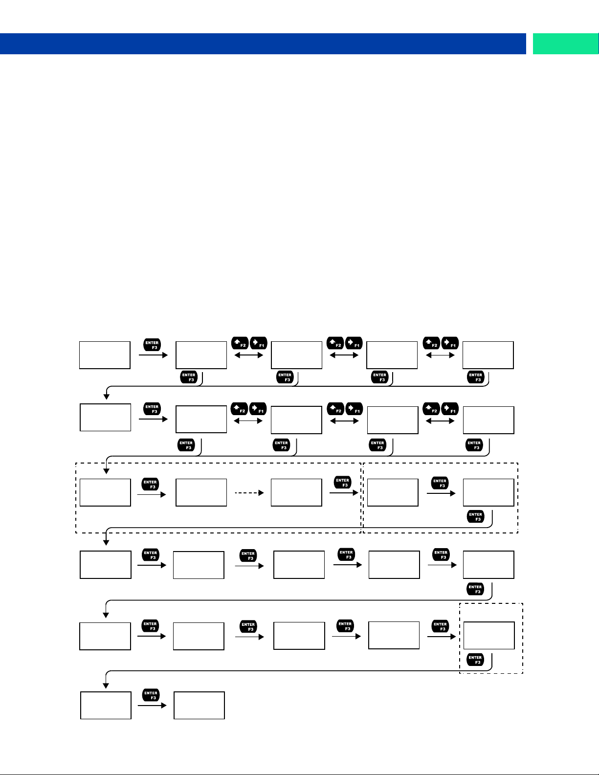
Alarm outputs may be assigned to the rate, total, grand total, or the digital input. When assigned to the
rate, the alarm may be set as either a high alarm or a low alarm. Alarm actions (AUTO, AUTO.MAN, LATCH,
L-CLEAR) determine how and when the alarm should be reset. They operate as follows:
• Automatic (AUTO): Alarm will reset automatically once the alarm condition has cleared.
• Automatic/Manual (AUTO.MAN): Alarm will reset automatically once the alarm condition has
cleared but can also be reset using the Enter button (or whichever function key is set to
acknowledge).
• Latching (LATCH): Alarm will not reset automatically even if the alarm condition has cleared.
Press the Enter button at any time to acknowledge the alarm.
• Latching with Reset after Clear (L-CLEAR): Alarm must be reset manually and can only be
done so after the alarm condition has cleared. Press the Enter (ACK) button after the alarm con-
dition has cleared to reset the alarm.
If the alarm is set to rate, a set and reset point must be programmed. The set point is the display value at
which the alarm will turn on and the reset point is the display value at which the alarm will turn off. If the
set point is lower than the reset point, the alarm will be a low alarm; if the set point is higher than the reset
point, the alarm will be a high alarm. If the alarm is set to total or grand total, only a set point needs to be
programmed. The digital input alarm will engage whenever the digital input is triggered.
For all alarms, a delay before the alarm is turned on or off may be set, as well as a failsafe feature which
will inverse the on/off programming.
Alarm states will be displayed on the meter even if no open collector output is physically connected. The
alarm indicator (!) will display as well as optional red LED backlight, flashing rate, total, or grand total
value (rate, total, or grand total alarms only), and a programmable alarm message.
Find Quality Products Online at: [email protected]
www.GlobalTestSupply.com
31
Page 32
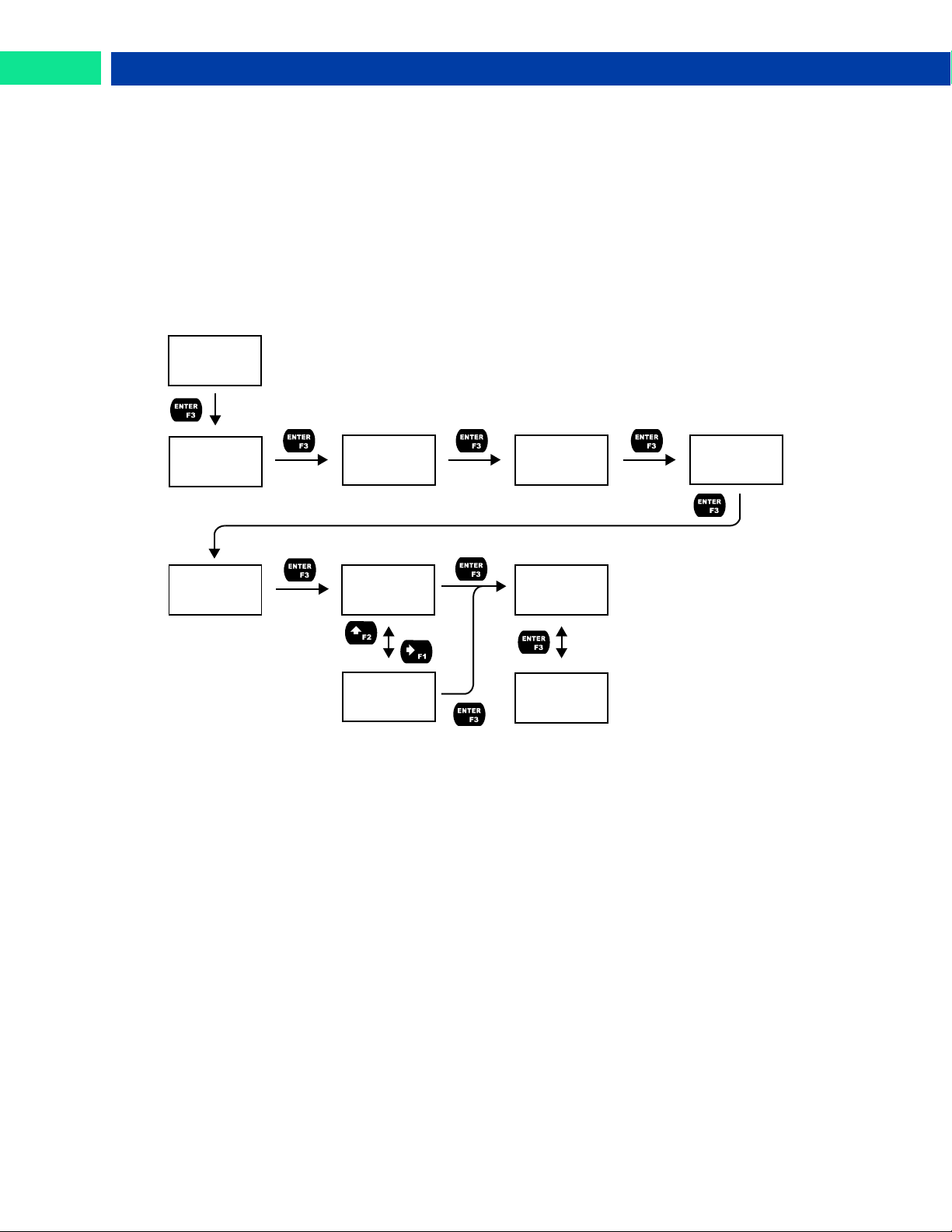
Loop Leader PD6620 Series Loop-Powered Rate/Totalizer Instruction Manual
OUT 1
TIMER
TIMER
OFF.DLAY
TIMER
ON TIME
TIMER
MODE
TIMER
START
MODE
CONT
MODE
ONE.SHOT
H.MM.SS
00.01.00
H.MM.SS
00.00.01
TIMER
STOP
Timer (TIMER)
The timer output may be set to generate the timed pulse only once (ONESHOT) or continuously (CONT).
The timer output produces a constant width pulse at a constant frequency, if set as continuous timer.
Program the Off Delay (OFF.DLAY) from 1 second to 99 hours 59 minutes and 59 seconds. This is the
time it takes from selecting START to turning on the output and for how long the output is off in continuous
mode.
Program the On Time (ONTIME) for the active low pulse from 1 second to 99 hours 59 minutes and 59
seconds (pulse width). This is the period of time for which the output will remain on.
Select Start (START) to begin outputting the constant timed pulse.
Select Stop (STOP) to end outputting the constant timed pulse.
Function keys or the digital input may be assigned to start and stop timer functions (see the USER menu
in Advanced).
Stopwatch (STPWATCH)
The stopwatch function may be used to manually run and control a process for a specific time interval up
to 99 hrs., 59 min, and 59 seconds. The stopwatch function may be assigned to any open collector. There
are three settings needed to use the function effectively.
1. Assign stopwatch to either top or bottom display line
2. Assign the open collector or relay to control the process (on/off)
3. Assign a function key or digital input to start/stop the stopwatch
Application Example
In order to maintain consistency of a product, it is necessary to take and test samples at different times
throughout the day. The stopwatch function is used to open and close a solenoid valve to know the exact
amount of time needed to complete the desired sample. Once this is determined, the timer function can
be used to automatically take a sample (batch) based on the time determined using the stopwatch function.
Setup: Assign the following to Stopwatch Function
Procedure
• Bottom display line
• Relay 1
• F3: Start/Stop
• Press F3 to start the stopwatch; relay 1 turns on and the process starts running.
• Press F3 to stop the stopwatch; relay 1 turns off and the process stops.
• The bottom display indicates the time it took to complete the sample.
32
Find Quality Products Online at: [email protected]
www.GlobalTestSupply.com
Page 33
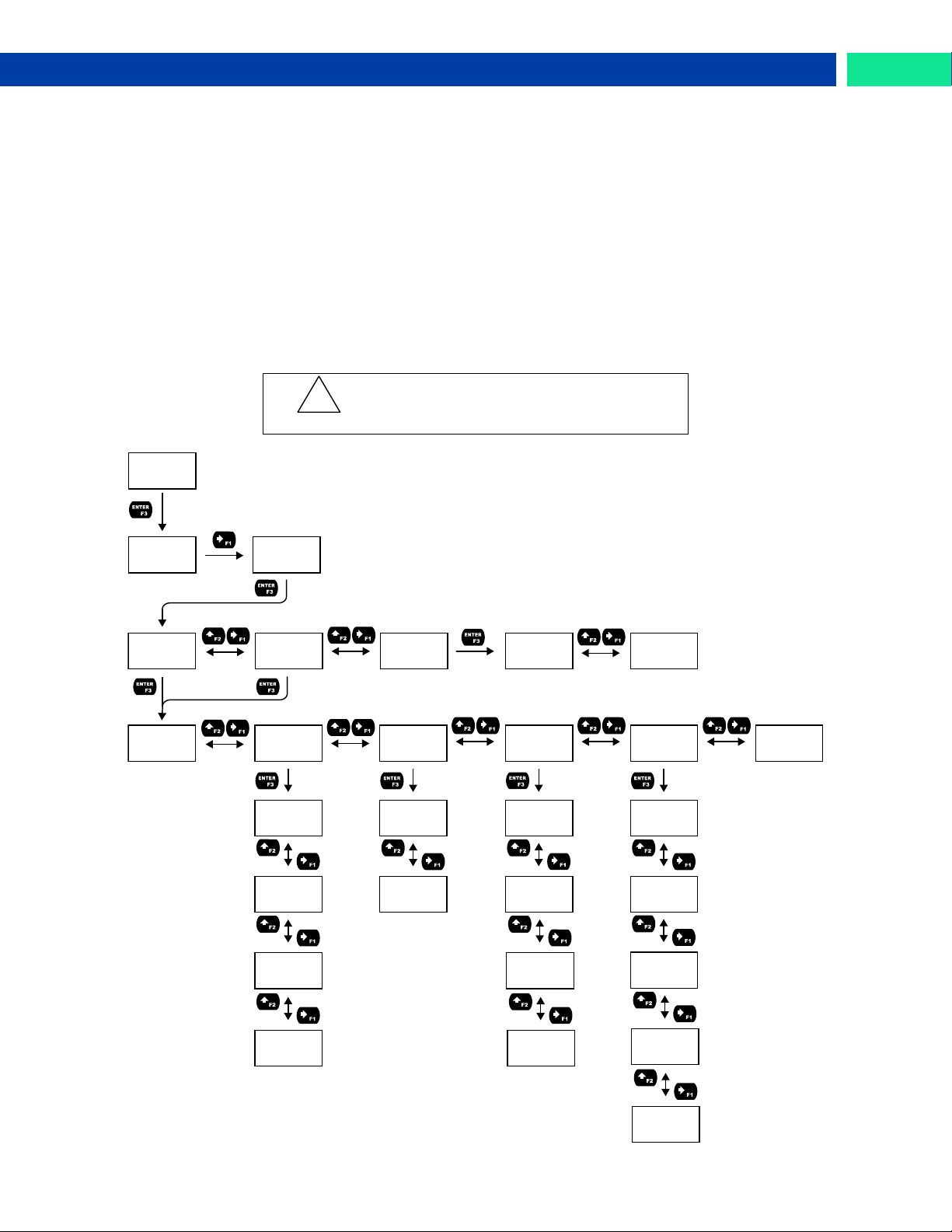
Loop Leader PD6620 Series Loop-Powered Rate/Totalizer Instruction Manual
Caution!
During setup, the relays do not follow the
input and they will remain in the state
found prior to entering the Relay menu.
!
SETUP
OUTPUT
OPEN
COLLECTR
OUT
RELAY
RELAY
OUTPUT1
RELAY
OUTPUT2
RELAY
INFO
INFO
RELAY 1
INFO
RELAY 2
RLY 1
DISABLE
RLY 1
ALARM
RLY 1
SAMPLE
RLY 1
TIMER
ALARM
RATE
ALARM
D.INPUT
TIMER
OFF.DLAY
TIMER
ON TIME
TIMER
MODE
TIMER
START
SAMPL
TOTAL
SAMPL
GTOTAL
RLY 1
BATCH
BATCH
COUNT
BATCH
MAXIMUM
BATCH
MODE
BATCH
PRESET
BATCH
DELAY
ALARM
TOTAL
ALARM
GTOTAL
RLY 1
STPWATCH
Solid State Relay Outputs (RELAY)
The meter is optionally equipped with two solid state relays that may be set up for alarms, sample, timer,
or batch control. Alternatively, they may be disabled.
Alarms are available based on the rate, total, or grand total value, or the digital input. The alarm status
will show on the display even if the output is not wired.
Sample will engage the relay for a programmed period of time when either the total or the grand total
have reach a programmed amount.
A timer output (TIMER) turns the relay on and off at the specified time intervals. The timer can be set as
single-shot or continuous timer.
For use in batch control applications, the meter relays may be set to batch. This will enable the batch
control features of the meter.
The stopwatch output (STPWATCH) allows the relay to be manually activated by starting the stopwatch.
The stopwatch count can be displayed on the top or bottom line.
The output may be disabled by selecting DISABLE.
Find Quality Products Online at: [email protected]
www.GlobalTestSupply.com
33
Page 34
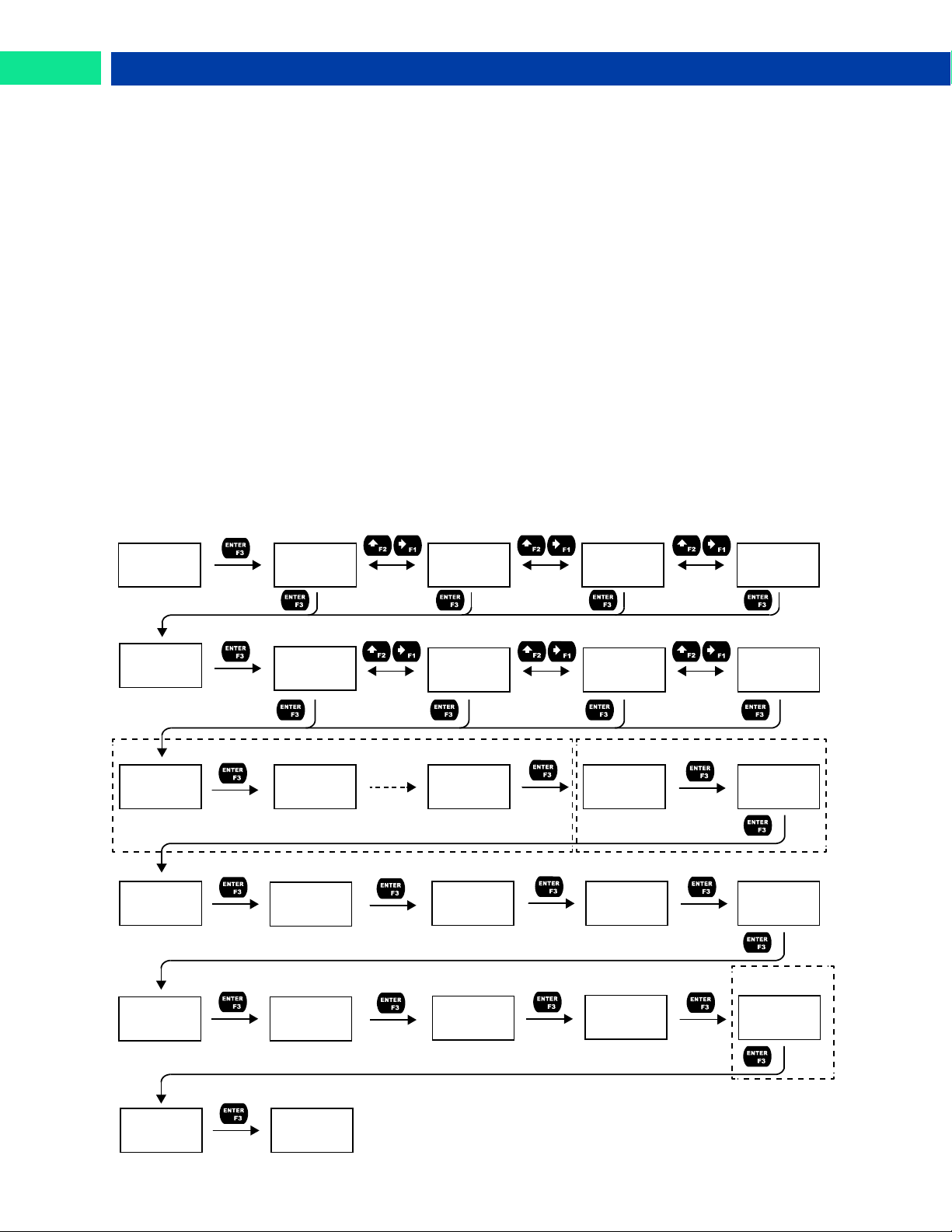
Loop Leader PD6620 Series Loop-Powered Rate/Totalizer Instruction Manual
RLY 1
ALARM
ALARM
D.INPUT
ALARM
ACTION
ACTN
AUTO
ACTN
AUTO.MAN
ACTN
LATCH
ACTN
L-CLEAR
SET
+00,040.00
SET
GAL
Flashes
Units
ALARM
RESET
ALARM
SET
RESET
+00,030.00
ALARM
DELAY
DELAY
ON
TIME
0000 SEC
DELAY
OFF
TIME
0000 SEC
ALARM
FAILSAFE
Rate, Total, GTotal Alarm Only
FSAFE
OFF
ALARM
DISPLAY
RED
ON
FLASH
ON
ALARM
GTOTAL
Rate Alarm Only
Rate, Total, Gr.
ALARM
RATE
ALARM
TOTAL
MSG
ON
MSG
ALARM 1
Total Alarm Only
Alarm (ALARM)
Alarm outputs may be assigned to the rate, total, or grand total values, or the digital input. When assigned
to the rate, the alarm may be set as either a high alarm or a low alarm. Alarm actions (AUTO, AUTO.MAN,
LATCH, L-CLEAR) determine how and when the alarm should be reset. They operate as follows:
• Automatic (AUTO): Alarm will reset automatically once the alarm condition has cleared.
• Automatic/Manual (AUTO.MAN): Alarm will reset automatically once the alarm condition has
cleared but can also be reset using the Enter button (or whichever function key is set to
acknowledge).
• Latching (LATCH): Alarm will not reset automatically even if the alarm condition has cleared.
Press the Enter button at any time to acknowledge the alarm.
• Latching with Reset after Clear (L-CLEAR): Alarm must be reset manually and can only be
done so after the alarm condition has cleared. Press the Enter (ACK) button after the alarm con-
dition has cleared to reset the alarm.
If the alarm is set to rate, a set and reset point must be programmed. The set point is the display value at
which the alarm will turn on and the reset point is the display value at which the alarm will turn off. If the
set point is lower than the reset point, the alarm will be a low alarm; if the set point is higher than the reset
point, the alarm will be a high alarm. If the alarm is set to total or grand total, only a set point needs to be
programmed. The digital input alarm will trigger whenever the digital input is triggered.
For all alarms, a delay before the alarm is turned on or off may be set, as well as a failsafe feature which
will inverse the on/off programming.
Alarm states will be displayed on the meter even if no relay output is physically connected. The alarm indicator (!) will display as well as optional red LED backlight, flashing rate, total, or grand total value (rate,
total, or grand total alarms only), and a programmable alarm message.
Find Quality Products Online at: [email protected]
34
www.GlobalTestSupply.com
Page 35
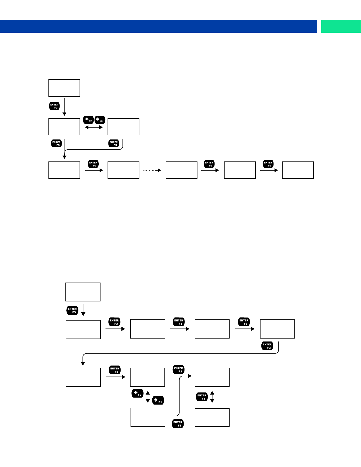
Loop Leader PD6620 Series Loop-Powered Rate/Totalizer Instruction Manual
TOTAL
COUNT
COUNT
GAL
COUNT
0,001,000.0
SAMPL
TIME
TIME
0010 SEC
RLY 1
SAMPLE
SAMPL
TOTAL
SAMPL
GTOTAL
Flashes
Units
RLY 1
TIMER
TIMER
OFF.DLAY
TIMER
ON TIME
TIMER
MODE
TIMER
START
MODE
CONT
MODE
ONE.SHOT
H.MM.SS
00.01.00
H.MM.SS
00.00.01
TIMER
STOP
Sample (SAMPLE)
A relay set to sample will trigger when the total or grand total value has incremented by a programmed
amount. The relay can be programmed to stay on for a specified amount of time.
For example: if a relay is set to sample the total with a COUNT of 1,000 and a TIME of 10 seconds, the
relay will engage for 10 seconds whenever the total has incremented by 1,000 (e.g. 1000, 2000, 3000).
Timer (TIMER)
The timer output may be set to generate the timed pulse only once (ONESHOT) or continuously (CONT).
The timer output produces a constant width pulse at a constant frequency, if set as continuous timer.
Program the Off Delay (OFF.DLAY) from 1 second to 99 hours 59 minutes and 59 seconds. This is the
time it takes from selecting START to turning on the output and for how long the output is off in continuous
mode.
Program the On Time (ONTIME) for the active low pulse from 1 second to 99 hours 59 minutes and 59
seconds (pulse width). This is the period of time for which the output will remain on.
Select Start (START) to begin outputting the constant timed pulse.
Select Stop (STOP) to end outputting the constant timed pulse.
Function keys or the digital input may be assigned to start and stop timer functions (see the USER menu
in Advanced).
Find Quality Products Online at: [email protected]
www.GlobalTestSupply.com
35
Page 36
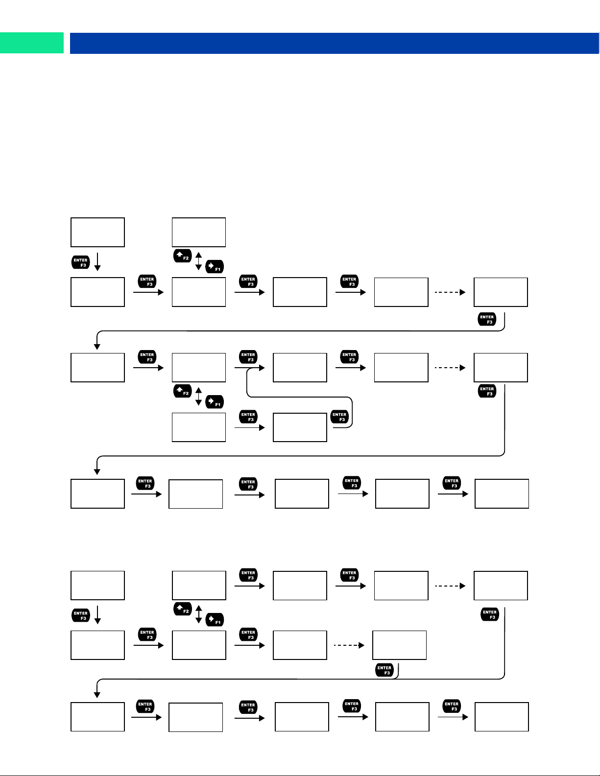
Loop Leader PD6620 Series Loop-Powered Rate/Totalizer Instruction Manual
RLY 1
BATCH
BATCH
COUNT
BATCH
MAXIMUM
BATCH
MODE
BATCH
PRESET
COUNT
UP
COUNT
DOWN
MAX
GAL
MAX
0,010,000.0
Flashes
Units
MODE
MANUAL
MODE
AUTO
PSET
GAL
PSET
0,001,000.0
Flashes
Units
BATCH
DELAY
DELAY
ON
TIME
0000 SEC
DELAY
OFF
TIME
0000 SEC
DELAY
9999 SEC
RLY 2
BATCH
BATCH
PRECLOSE
YES
PRECLOSE
NO
PRECLOSE
CLOSE
GAL
CLOSE
0,000,200.0
Flashes
Units
BATCH
DELAY
DELAY
ON
TIME
0000 SEC
DELAY
OFF
TIME
0000 SEC
BATCH
PRESET2
PSET2
GAL
PSET2
0,000,800.0
Flashes
Units
Batch Control (BATCH)
Selecting batch control for relay 1 will enable batching features on the meter. The top display will be
changed to show the total and the bottom display will be changed to display the preset batch amount. The
function keys will be changed so that F1 starts a batch, F2 opens the preset menu to allow the preset
value to be changed, and F3 stops the currently running batch. Enabling batch control for relay 1 will allow access to the BATCH menu under relay 2 (this menu does not appear by default).
Batch Control Relay 1
The batch total can be set to count UP or DOWN. The batch MAXIMUM is the max preset amount that can
be batched. Batching can be set to either manual or automatic operation (MANUAL or AUTO). If setting
batching to automatic, a delay before the next batch is started must be programmed. The PRESET
amount is the value at which the batch will stop and can be programmed up to the value assigned in the
MAXIMUM menu. An on and off delay may be set for batching relays.
The BATCH option only appears under relay 2 if relay 1 has also been set to batch control. The second
relay may be programmed as a preclose relay or as another batching relay with its own preset amount.
Find Quality Products Online at: [email protected]
36
Batch Control Relay 2
www.GlobalTestSupply.com
Page 37
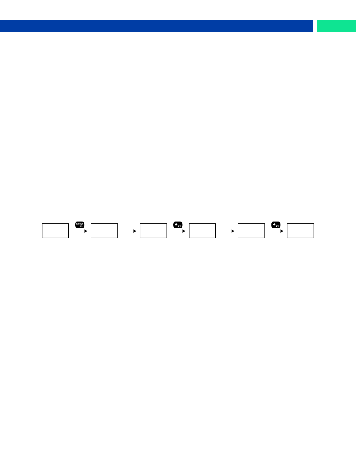
Loop Leader PD6620 Series Loop-Powered Rate/Totalizer Instruction Manual
INFO
RELAY 1
RELAY
RUNTIME
Flashes
Momentarily
TIME
195.0 H
CYCLE
COUNT
CYCLE
51
RLY 1
CLEAR?
Flashes
Momentarily
Stopwatch (STPWATCH)
The stopwatch function may be used to manually run and control a process for a specific time interval up
to 99 hrs., 59 min, and 59 seconds. The stopwatch function may be assigned to any relay. There are
three settings needed to use the function effectively.
1. Assign stopwatch to either top or bottom display line
2. Assign the open collector or relay to control the process (on/off)
3. Assign a function key or digital input to start/stop the stopwatch
Application Example
In order to maintain consistency of a product, it is necessary to take and test samples at different times
throughout the day. The stopwatch function is used to open and close a solenoid valve to know the exact
amount of time needed to complete the desired sample. Once this is determined, the timer function can
be used to automatically take a sample (batch) based on the time determined using the stopwatch function.
Setup: Assign the following to Stopwatch Function
• Bottom display line
• Relay 1
• F3: Start/Stop
Procedure
• Press F3 to start the stopwatch; relay 1 turns on and the process starts running.
• Press F3 to stop the stopwatch; relay 1 turns off and the process stops.
• The bottom display indicates the time it took to complete the sample.
Relay Information (INFO)
The relay information menu shows run times and cycle counts for each relay. These values may be
cleared at any time by selecting the Clear option (CLEAR?).
Find Quality Products Online at: [email protected]
www.GlobalTestSupply.com
37
Page 38
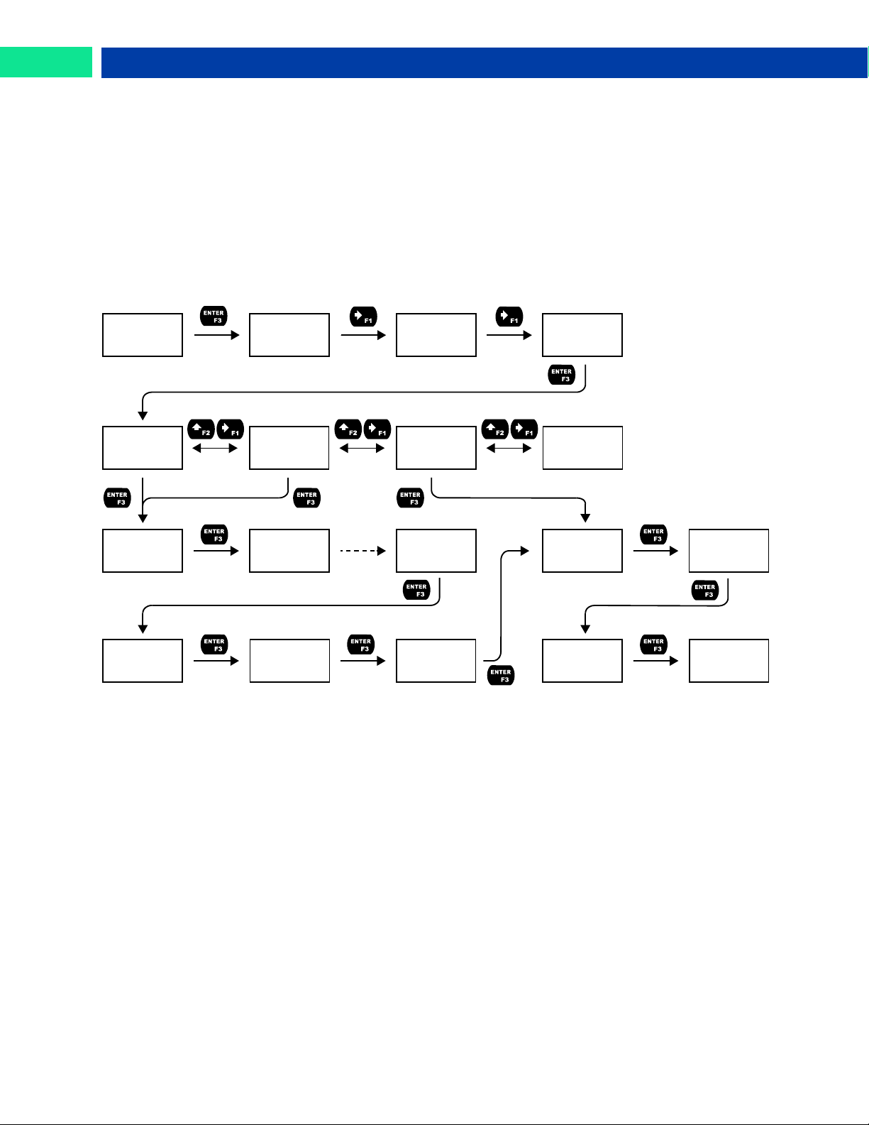
Loop Leader PD6620 Series Loop-Powered Rate/Totalizer Instruction Manual
SETUP
OUTPUT
OPEN
COLLECTR
OUT
RELAY
OUT
4-20 mA
4-20
RETRANS
4-20
DISABLE
DSP 1
+00,000.00
DSP 1
GAL
Flashes
Units
OUT 1
04.000
DSP 2
+00,100.00
OUT 2
20.000
AOUT
UNDER
U-RNG
DISABLE
AOUT
OVER
O-RNG
DISABLE
AOUT
SCALE
4-20
RATE
4-20
TOTAL
4-20 mA Output (4-20 mA)
The 4-20 mA menu is used to scale the 4-20 mA output based on display values. This menu is not
present on models without a 4-20 mA output option.
The 4-20 mA analog output (if equipped) can be scaled to provide a 4-20 mA signal for the rate or total
display range or to simply retransmit the 4-20 mA input. The output may be disabled (DISABLE), and will
only output the minimum signal.
Overrange and underrange values determine what mA signal the meter will output if the mA input is
underrange (<3.5 mA) or overrange (>20.5 mA). This value may be set to 1-mA, 3.5-mA, 3.8-mA, 20.5mA, 20.8-mA, 23-mA, or disabled.
No equipment is needed to scale the analog output; simply program two display values and
corresponding mA output signals.
Rate or Total (RATE or TOTAL)
To scale the analog output, enter display value 1 and a corresponding analog output value for this
display, then enter display value 2 and a corresponding analog output value for this display value. This
Find Quality Products Online at: [email protected]
will provide a linearly scaled analog output.
This option will retransmit the 4-20 mA analog input without the need to scale the output.
The Control menu is used to control the open collector outputs, 4-20 mA analog output, or the relays
manually, ignoring the input. Each open collector, relay, and analog output can be programmed independently for manual control. Selecting automatic control sets all relays and analog output for automatic
operation.
38
Retransmit (RETRANS)
Output Control (CONTROL)
www.GlobalTestSupply.com
Page 39
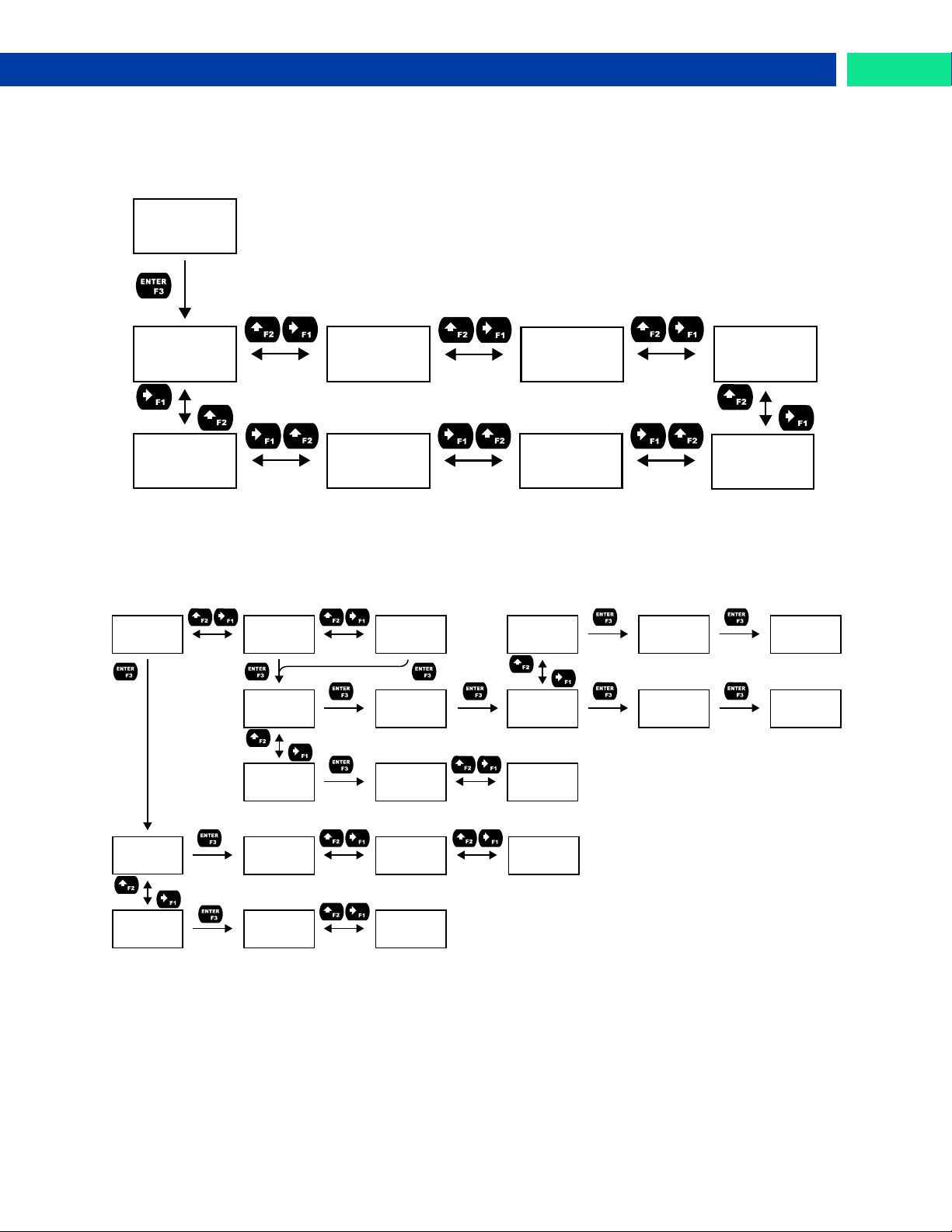
Loop Leader PD6620 Series Loop-Powered Rate/Totalizer Instruction Manual
SETUP
ADVANCED
ADV
RATE
CUTOFF
SYSTEM USER PASSWRD
FILTER
ADV
TOTAL
ADV
GTOTAL
ADV
RATE
RATE
FUNCTION
RATE
SCALE.CAL
ADV
TOTAL
LIMIT
13-DIGIT
RATE
LINEAR
RATE
SQROOT
RATE
EXPONENT
SCALE
RATE
CAL
RATE
ADV
GTOTAL
TOTAL
COUNT
TOTAL
RESET
COUNT
LIMIT
LIMIT
8-DIGIT
COUNT
INITIAL
COUNT
INITIAL
00000
0,000,000.0
COUNT
0,000,000.0
RESET
ENABLE
RESET
DISABLE
Advanced Features Menu (ADVANCED)
To simplify the setup process, functions not needed for most applications are located in the Advanced
Features menu. The options under advanced features include: advanced rate, total, and grand total
setup, cutoff, filter, password, function key programming, and system settings.
Advanced Rate, Total, and Grand Total Setup (ADV RATE, TOTAL, GTOTAL)
The Advanced Rate menu contains options to apply signal input conditioning functions to the input and
scale/calibrate the input signal. The Advanced Total and Advanced Grand Total menus contain options to
change how the value is incremented and if it can be manually reset by the user.
Find Quality Products Online at: [email protected]
www.GlobalTestSupply.com
39
Page 40

Loop Leader PD6620 Series Loop-Powered Rate/Totalizer Instruction Manual
Signal Input Conditioning Functions (FUNCTION)
The Function menu is used to select the signal input conditioner applied to the input: linear, square root,
or programmable exponent calculation. Multi-point linearization is part of the linear function selection.
Meters are set up at the factory for linear function with 2-point linearization. The linear function provides a
display that is linear with respect to the input signal.
Square Root Linearization (SQROOT)
The square root function can be used to linearize the signal from a differential pressure transmitter and
display flow rate in engineering units.
Programmable Exponent Linearization (EXPONENT)
The programmable exponent can be used to linearize the signal from level transmitters in open-channel
flow applications using weirs and flumes.
Multi-Point Linearization (LINEAR)
Meters are set up at the factory for linear function with 2-point linearization. Up to 32 linearization points
can be selected for the scaled value under the linear function. Multi-point linearization can be used to linearize the display for non-linear signals to convert level to flow using weirs and flumes with complex exponent.
Advanced Total and Grand Total Programming (ADV TOTAL & ADV GTOTAL)
The advanced total and grand total menu contain the count (COUNT) and reset (RESET) menus. The
count menu allows the digit limit to be selected between 8-digit (bottom line only) and 13-digit (uses top
and bottom line to display full number) and an initial value at which the total or grand total should begin
counting to be set.
When using a 13-digit total or grand total, press the function key assigned to display (default: F1) to view
the full amount once the value has exceeded 100,000,000 (decimal places are automatically truncated). If
a 13-digit total or grand total is displayed on the bottom line and the value has exceeded eight digits, the
truncated value will flash to indicate that it is not the complete value. To display 13-digit grand total, assigned the top and bottom line to grand total.
The reset menu allows the resetting of total or grand total to zero to be enabled or disabled.
Non-Resettable Grand Total
The grand total reset may be permanently disabled by selecting YES at the PERMLOCK menu after disabling grand total reset. Use caution when selecting the PERMLOCK feature as, once grand total reset has
been permanently locked, it cannot be unlocked.
40
Find Quality Products Online at: [email protected]
www.GlobalTestSupply.com
Page 41
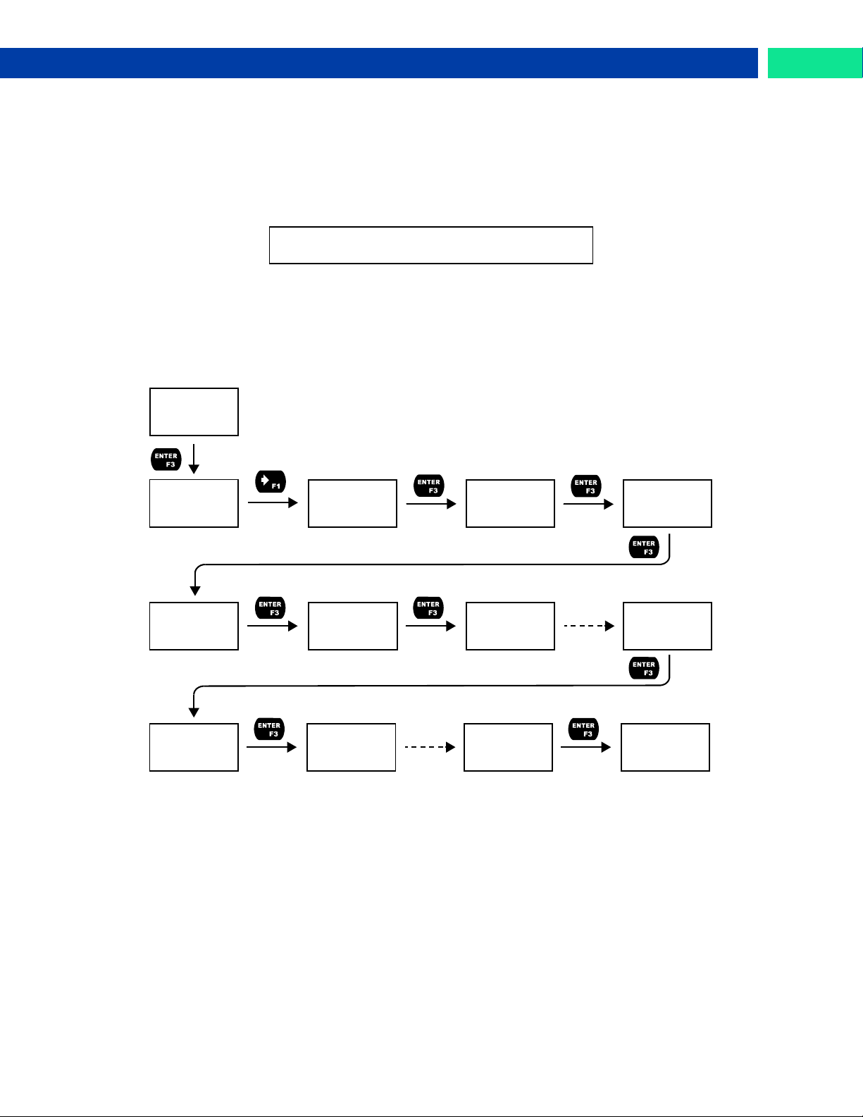
Loop Leader PD6620 Series Loop-Powered Rate/Totalizer Instruction Manual
To scale the meter without a signal source, refer
to Setting Up the Input Signal (INPUT), page 24.
RATE
SCALE.CAL
CAL
UNITS
TIME
/SECOND
UNIT
GAL/S
DSP 1
GAL/S
Flashes
Units
SCALE
RATE
CAL
RATE
INP 1
04.000 mA
DSP 1
+00,000.00
DSP 2
GAL
Flashes
Units
INP 2
20.000 mA
DSP 2
+00,100.00
SAVE?
Advanced Scaling and Calibration (SCALE.CAL)
This menu offers options to scale or calibrate the meter.
Scaling the Input (SCALE)
The scale menu in the Advanced menu is the same as the scale menu in the Input menu. See Setting Up
the Input Signal (INPUT) on page 24 for details about scaling the meter.
Calibrating the Input (CAL)
The meter can be calibrated to display the process in engineering units by applying the appropriate input
signal and following the calibration procedure. The CAL menu should be used with a live signal coming
from a 4-20 mA transmitter connected to the process being measured.
During calibration, the mA input value will be displayed as INP 1 and INP 2. Adjust the input source until the desired mA value is shown. The use of a calibrated signal source is strongly recommended.
Find Quality Products Online at: [email protected]
1. After accessing the SCALE.CAL menu, press the Right-Arrow button to scroll to the Calibration
menu (CAL RATE) and press Enter.
2. Select the appropriate units for the desired process variable, then press Enter. For information on
3. The meter displays INP 1. Apply a known signal and press Enter. The display will flash while
4. After the signal is accepted, the meter displays DSP 1. Enter a corresponding display value for the
5. The meter displays INP 2. Apply a known signal and press Enter. The display will flash while
6. After the signal is accepted, the meter displays DSP 2. Enter a corresponding display value for the
7. After completing calibration, the SAVE? display will need to be acknowledged using the Enter key
units, see Available Unit Classes and Units on page 25.
accepting the signal.
signal input, and press Enter to accept.
accepting the signal.
signal input and press Enter to accept.
before calibration will take effect.
www.GlobalTestSupply.com
41
Page 42
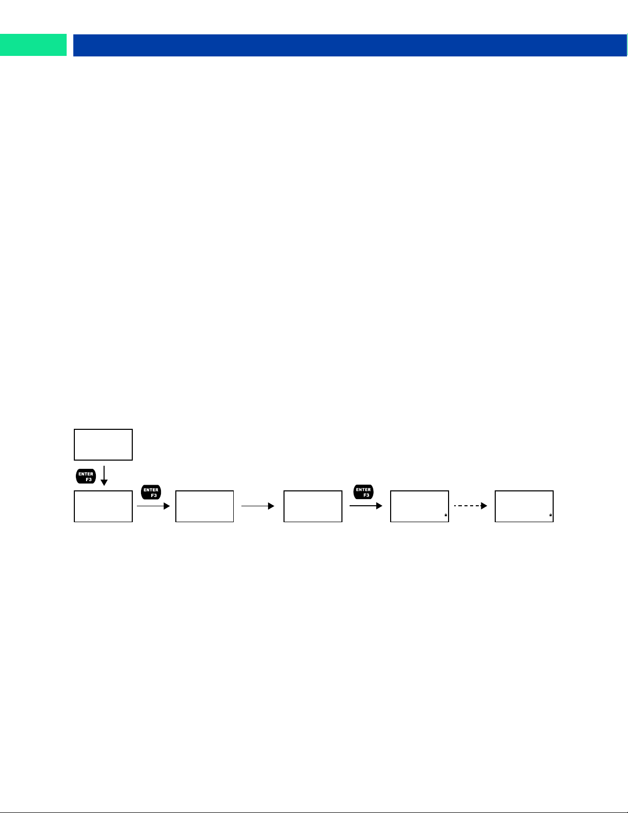
Loop Leader PD6620 Series Loop-Powered Rate/Totalizer Instruction Manual
LOCKED
PASSWRD
PASS
MAIN
LOCK
00000
LOCK
12345
Enter Numeric
Password
PASSWRD
Flashes
Momentarily
Low-Flow Cutoff (CUTOFF)
The low-flow cutoff feature allows the meter to be programmed so that the output from a flowmeter always
displays zero on the meter at low flow rates.
The cutoff value may be programmed from 0 to 999999.9. The meter will display zero below the cutoff
value. The cutoff may also be disabled to display negative values.
Noise Filter (FILTER)
The noise filter is available for unusually noisy signals that cause an unstable process variable display.
The noise filter averages the input signal over a certain period. The filter level determines the length of
time over which the signal is averaged. The filter level can be set between 1 and 16 seconds or turned
off. The higher the filter level, the longer the averaging time and so the longer it takes the display to settle
to its final value. Setting the filter level to off disables the filter function.
Noise Filter Bypass (BYPAS)
The noise filter bypass changes the behavior of the meter so that small variations in the signal are filtered
out but large abrupt changes in the input signal are displayed immediately. The bypass value determines
the minimum amount of signal change to be displayed immediately. All signal changes smaller than the
bypass value are filtered or averaged by the meter. The noise filter bypass may be set between 0.0 and
99.9% of full scale.
Enabling Password Protection (PASSWRD)
The Password menu is used for programming security to prevent unauthorized changes to the programmed parameter settings. There are three password types available: Main, Total, and Grand Total.
The Main password prevents access to the meter Programming Mode. Total and Grand Total passwords
prevent resetting of and changes to the total and grand total, respectively.
In order to set a password, enter the Password menu and program a five-digit password. When the Main
password has been enabled, the lock icon will display in the lower right of the display (PD6622/26 only).
For instructions on how to program numeric values see Setting Numeric Values, page 23.
Making Changes to a Password Protected Meter
If the Main password is enabled, the meter will display the message LOCKED when the Menu button is
pressed. If the Total or Grand Total passwords are enabled, the meter will display the message LOCKED
when trying to reset or change the total or grand total. Press the Enter button while the message is being
displayed and enter the correct password to gain access to the menu. After exiting Programming Mode,
the meter returns to its password protected condition.
Disabling Password Protection
To disable the Main, Total, or Grand Total passwords, access the Password menu and clear the desired
password either by pressing and holding the Right Arrow button until all digits reset to zero or manually
changing all of the digits to zero. When the Enter button is pressed, the meter will display UNLOCKED and
will no longer require a password to access Programming Mode, or a password to reset or change the
total or grand total, depending on which password was cleared.
Note: If the meter is password protected and the password has been forgotten, the password may be
overridden using the master password: 50865
Find Quality Products Online at: [email protected]
42
www.GlobalTestSupply.com
Page 43
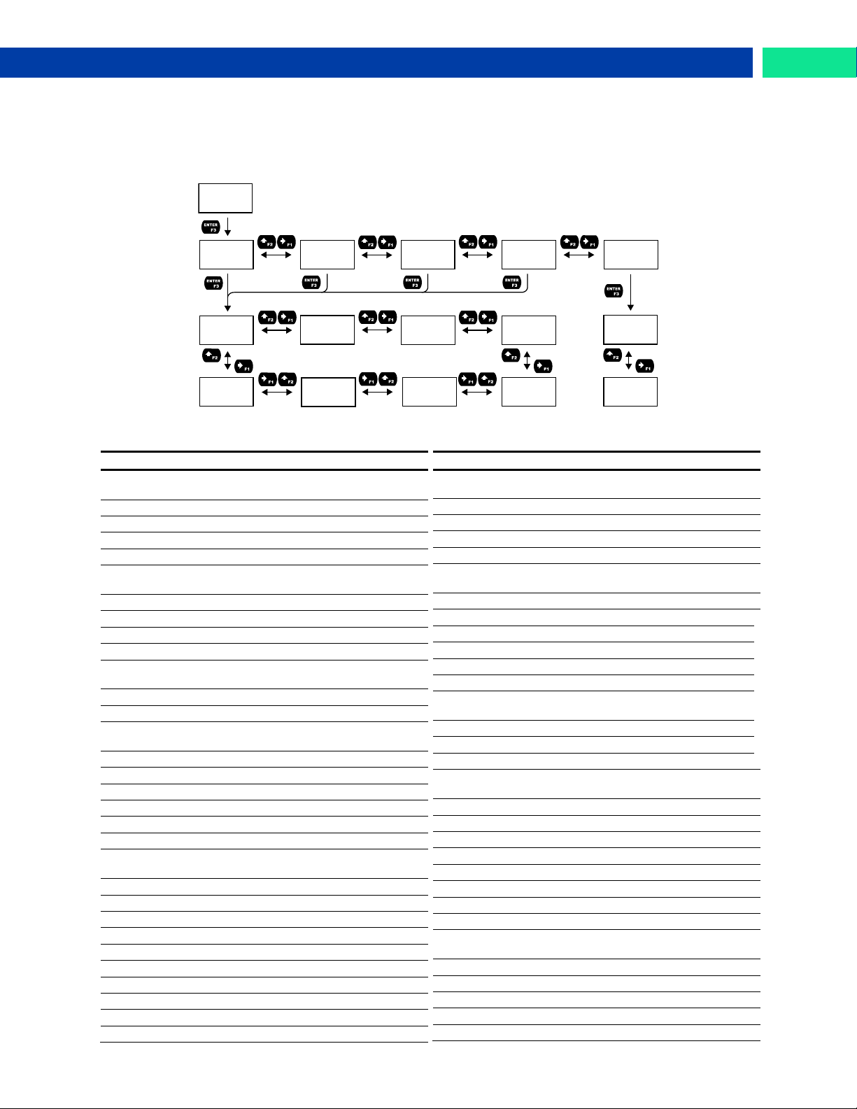
Loop Leader PD6620 Series Loop-Powered Rate/Totalizer Instruction Manual
Display
Description
DISP FN
Set the function key or digital input to display a value
DISPLAY
Cycle max, min, rate, total, and grand total
D RATE
Display the rate
D TOTAL
Display the total
DISP GT
Display the grand total
PCT.RATE
Display the rate’s percentage of max (20
mA)
D UNITS
Display rate, total, and grand total units
D TAG
Display the tags
DISPMIN
Display the minimum rate value
DISPMAX
Display the maximum rate value
MIN MAX
Display the minimum and maximum rate
value
D mA IN
Display the current mA input value
D mAOUT
Display the current mA output value
MENU FN
Set the function key or digital input to access a menu
RLYINFO
Go to relay information menu (INFO)
MANCTRL
Go to output control menu (CONTROL)
TIMR OC1
Open collector 1 timer
TIMR OC2
Open collector 2 timer
TIMER R1
Relay 1 timer
TIMER R2
Relay 2 timer
TIMER.FN
Set the function key or digital input to start
or stop a timer
STRT.ALL
Start all timers
STOP.ALL
Stop all timers
S.STP.ALL
Start or stop all timers
OC1
Start/stop open collector 1 timer
OC2
Start/stop open collector 2 timer
RLY1
Start/stop relay 1 timer
RLY2
Start/stop relay 2 timer
START
Start the selected timer output
STOP
Stop the selected timer output
STR-STP
Start or stop the selected timer output
Display
Description
BATCH.FN
Set the function key or digital input to
batch control
START
Start a batch
STOP
Stop a batch
STR-STP
Start or stop a batch
PRESET
Preset batch amount
ALARM.FN
Set the function key or digital input to
acknowledge an alarm
ACK
Acknowledge all active alarms
SETPOINT
View all output set points
SETPT.OC1
View open collector 1 set points
SETPT.OC2
View open collector 2 set points
SETPT.R1
View relay 1 set points
SETPT.R2
View relay 2 set points
SWATCH.FN
Set the function key or digital input to
activate stopwatch
START
Start the stopwatch
STOP
Pause/Stop the stopwatch
STR-STP
Start or stop the stopwatch
HOLD FN
Set the function key or digital input to hold
an output
HOLD.OUT
Hold all outputs
HLD.UNHLD
Hold or un-hold all outputs
OC1+2
Hold/un-hold open collector outputs
RLY1+2
Hold/un-hold relay outputs
mAOUT
Hold/un-hold 4-20 mA output
HOLD
Hold selected output
HLD.UNHLD
Hold or un-hold selected output
DISABLE
Disable function key or digital input
RST FN
Set the function key or digital input to reset
a value
RESET
Reset min, max, or max/min PV value
R MIN.MAX
Reset max and min PV value
RST T
Reset the total
RST GT
Reset the grand total
RST T.GT
Reset the total and grand total
USER
USER
F1
USER
F2
USER
F3
USER
DI
USER
HINT
F1
DISP FN
F1
MENU FN
F1
TIMER.FN
F1
BATCH.FN
F1
HOLD FN
F1
RST FN
F1
DISABLE
HINT
OFF
HINT
ON
F1
ALARM.FN
Programmable Function Keys User Menu (USER)
The User menu allows the user to assign the front panel function keys F1, F2, and F3, and the digital input (located on the signal input connector) to access some of the menus or to activate certain functions
immediately (e.g. reset max & min, hold relay states, etc.). This allows the meter to be greatly customized
for use in specialized applications.
Function Keys & Digital Input Available Settings
Refer to the following table for descriptions of each available function key or digital input setting.
Find Quality Products Online at: [email protected]
www.GlobalTestSupply.com
43
Page 44
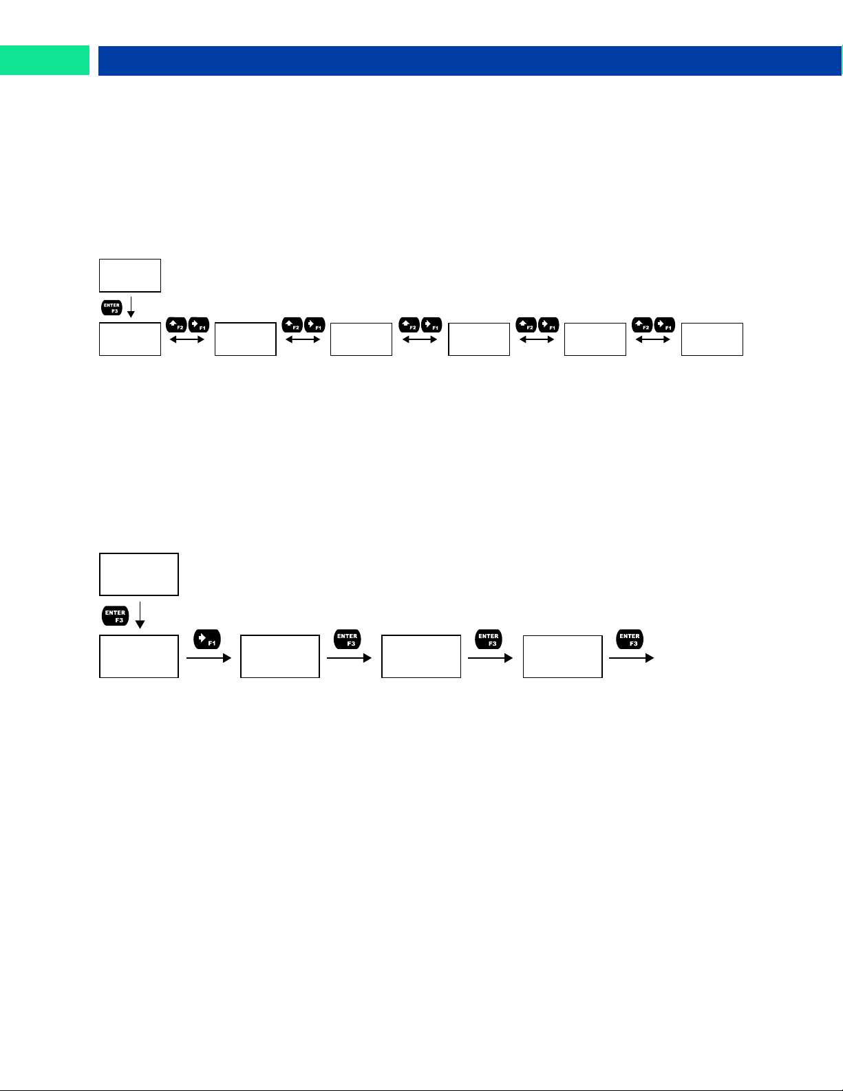
Loop Leader PD6620 Series Loop-Powered Rate/Totalizer Instruction Manual
SYSTEM
SYSTM
AOUTCAL
SYSTM
DEFAULT
SYSTM
TOTAL
SYSTM
BACKLITE
SYSTM
INFO
SYSTM
ICAL
SYSTEM
SYSTM
AOUTCAL
SYSTM
DEFAULT
LOAD?
DEFAULT
RESET
DFAULT?
Meter Loads
Default Settings
and Restarts
Enabling the Function Key Hint Feature (HINT)
Enabling the function key hint feature will cause a hint message to be displayed when pressing the F1,
F2, or F3 function keys. This text gives a brief description of what the button is programmed to do. Pressing that function key a second time will execute that action.
The hint feature does not affect the digital input (DI) which is intended for immediate execution.
Changing System Settings (SYSTEM)
The System menu contains the following menus: Analog Output Calibration, Restore Factory Defaults,
Totalizer, Backlight, Information, and Internal Calibration.
Analog Output Calibration (AOUTCAL)
To perform the analog output calibration, it is recommended to use a milliamp meter with a resolution of
at least 0.1 µA to measure the output current. The values saved internally during this procedure are used
for scaling the 4-20 mA output in the Setup menu.
Resetting the Meter to Factory Defaults (DEFAULT)
When the parameters have been changed in a way that is difficult to determine what’s happening, it might
be better to start the setup process from the factory defaults. To load factory defaults, enter the DEFAULT
menu under the SYSTEM menu and press enter twice in quick succession. The meter will load the default
settings and restart.
Disabling the Totalizer (TOTAL)
The totalizer can be disabled using the TOTAL menu. With the totalizer disabled, the meter will behave as
a PD6602 or PD6604 process meter. Refer to the PD6602/4 instruction manual for instructions about programming a PD6602 or PD6604 process meter.
Enabling or Disabling the Backlight (BACKLITE)
The backlight may be enabled or disabled using the Backlight menu. The backlight is enabled by default,
but the input must be wired appropriately in order for the backlight to function. See Safe Area Current
Loop (4-20 mA) Connections on page 14. The voltage drop is the same if the backlight is not wired or if it
is disabled in the menu.
Viewing System Information (INFO)
System information, such as software number, software version, model number, and system tag, may be
viewed in the INFO menu. Press the Right Arrow button to cycle through all available meter information.
Press Menu to go back to the previous menu.
Find Quality Products Online at: [email protected]
44
www.GlobalTestSupply.com
Page 45
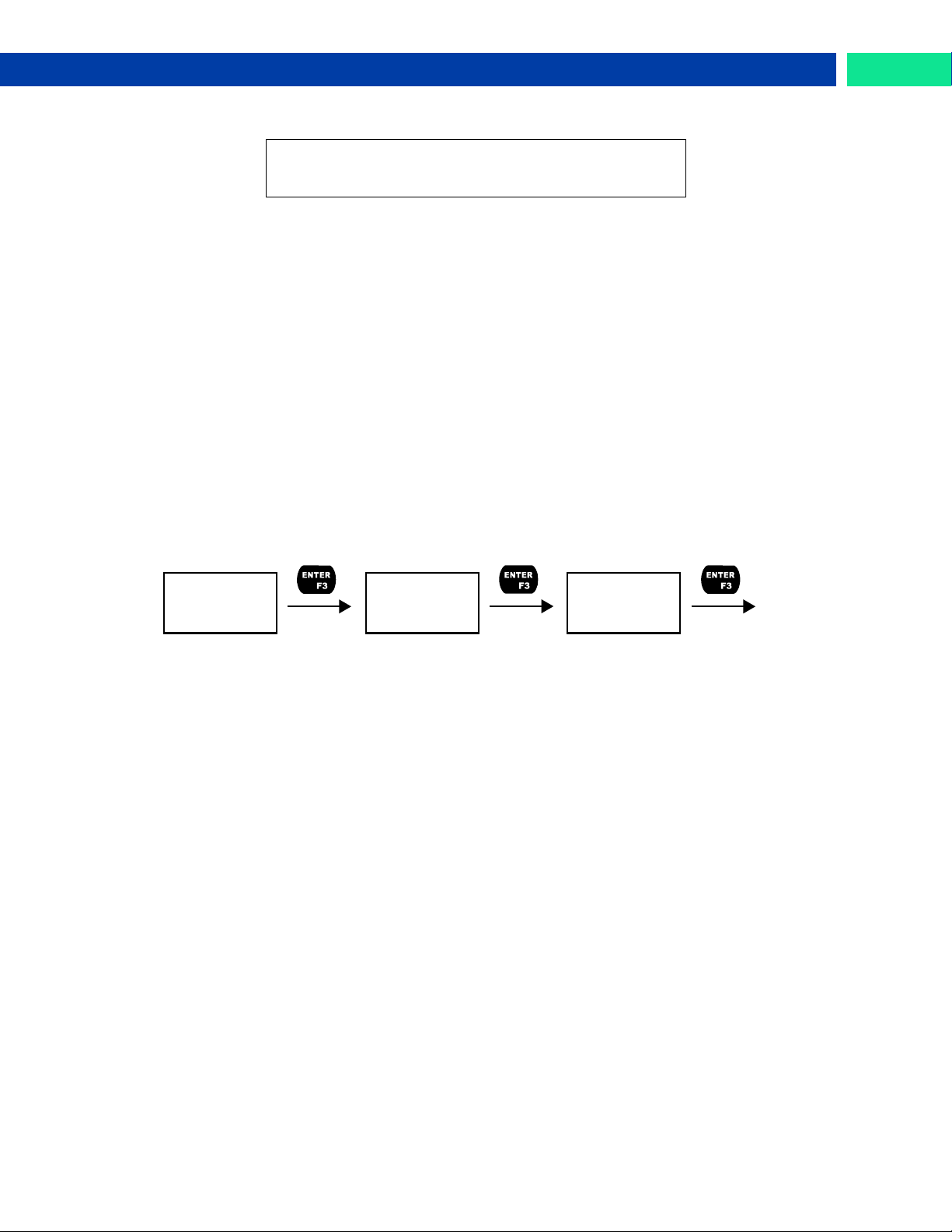
Loop Leader PD6620 Series Loop-Powered Rate/Totalizer Instruction Manual
The meter is factory calibrated prior to shipment to display
0 to 100, which corresponds to the 4-20 mA input. The
calibration equipment is traceable to NIST standards.
SYSTM
ICAL
ICAL
4.000 mA
Display
Flashes While
Accepting Input
ICAL
20.000 mA
Display
Flashes While
Accepting Input
Apply 4-mA
Signal
Apply 20-mA
Signal
Calibrating the Internal mA Reference (ICAL)
The use of calibrated signal sources is necessary to calibrate the internal source of the meter. The meter’s internal source is what allows the user to scale the meter without applying a signal.
Check calibration of the meter at least every 12 months.
Note: Allow the meter to warm up for at least 5 minutes before performing the internal source calibration
procedure.
The Internal Calibration menu is part of the Advanced menu. Internal Calibration is performed as follows:
1. Press the Menu button to enter Programming Mode.
2. Press the Right Arrow button twice and press Enter to access the Advanced menu.
3. Press the Up-Arrow button and press Enter to access the System menu.
4. Press the Up-Arrow button and press Enter to access the ICAL menu.
5. The meter displays low input current message (4.000 mA). Apply a 4-mA signal and press Enter.
The display flashes for a moment while the meter is accepting the low input signal.
6. After the display stops flashing, the display moves to the high input calibration (20.000 mA). Ap-
ply the high input signal and press Enter. The display will flash again while the meter is accepting
the high input signal.
Find Quality Products Online at: [email protected]
www.GlobalTestSupply.com
45
Page 46
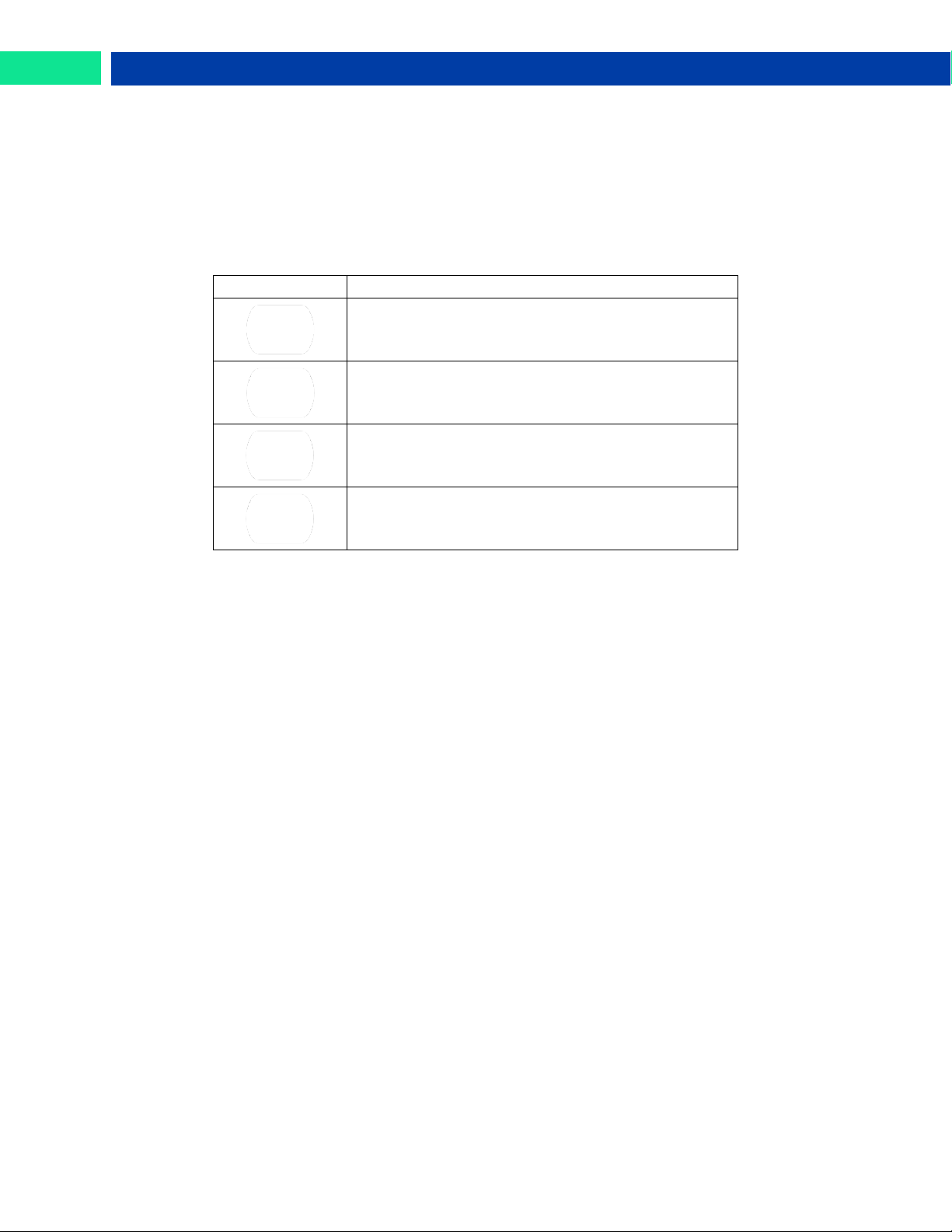
Loop Leader PD6620 Series Loop-Powered Rate/Totalizer Instruction Manual
Button Symbol
Description
Press to enter or exit Programming Mode, view settings, or exit max/min readings
Press to display grand total, max/min readings, or
other parameter/function assigned through the User
menu
Press to reset total, grand total, max/min readings, or
other parameter/function assigned through the User
menu
Press to acknowledge alarms or other parameters/function assigned through the User menu
Meter Operation
The meter is capable of accepting a 4-20 mA current signal and displaying it in engineering units from
-9,999 to 99,999 on the top line or from -9,999,999 to 99,999,999 on the bottom line. For example, a
4-20 mA signal could be displayed as -50.00 to 50.00.
The dual-line display can be customized by the user to operate in such a way as to satisfy a specific application. Typically, the top line is used for the rate variable while the bottom line is used for total, grand total,
engineering units, or custom tag.
Front Panel Buttons Operation
Function Keys Operation
During operation, the programmable function keys operate according to the way they have been programmed in the Advanced Features – User menu. The table above shows the factory default settings for
F1, F2, and F3.
A hint message may be enabled in order to provide a description of what each function key does prior to
executing their assigned function. See Enabling the Function Key Hint Feature (HINT) on page 44.
Digital Input Operation
A digital input is standard on the meter. This digital input is programmed identically to function keys F1,
F2, and F3. The input is triggered with a contact closure between DI+ and DI-, or with an active low signal. During operation, the digital input operates according to the way it has been programmed in the Ad-
vanced Features – User menu.
Maximum/Minimum Readings
The max & min readings (peak & valley) reached by the rate variable can be displayed either continuously or momentary:
1. Display briefly by pressing the F1 key (default) or assigning to any of the other function keys or to
the digital input in the User menu.
2. Display continuously by pressing the Enter button while the max/min is being displayed to lock
the display. Press Enter again to unlock.
Any of the F1-F3 function keys (buttons) and the digital input can be programmed to reset the max & min
readings. The meters are set at the factory to display the max reading by pressing the Right Arrow/F1
button and to use the Up-Arrow/F2 button to access the Reset menu. Press the Right Arrow button to cycle through the available parameters to reset.
Changing Engineering Units
It is possible to change the display units without the need to re-scale the meter. The UNITS menu within
the DISPLAY menu allows the unit of measure to be changed (e.g. from gallons/second (GAL/s) to liters/second (L/s)) and the meter will automatically convert the display values to the new unit of measure.
If entering a custom unit (CUSTOM), a custom conversion factor will need to be entered. See Changing the
Units (UNITS) on page 26.
Find Quality Products Online at: [email protected]
46
www.GlobalTestSupply.com
Page 47
Loop Leader PD6620 Series Loop-Powered Rate/Totalizer Instruction Manual
SYSTEM
SYSTM
AOUTCAL
SYSTM
DEFAULT
LOAD?
DEFAULT
RESET
DFAULT?
Meter Loads
Default Settings
and Restarts
Troubleshooting
Due to the many features and functions of the meter, it’s possible that the setup of the meter does not
agree with what an operator expects to see.
If the meter is not working as expected, refer to the recommendations below.
Reset Meter to Factory Defaults
When the parameters have been changed in a way that is difficult to determine what’s happening, it might
be better to start the setup process from the factory defaults.
To load factory defaults:
1. Press the Menu button to enter Programming Mode.
2. Press the Up-Arrow button twice and press Enter to access the Advanced menu.
3. Press the Up-Arrow button and press Enter to access the System menu.
4. Press the Right-Arrow button and press Enter to access the Default menu.
5. Press Enter twice in quick succession. The meter will load default settings and restart.
Determining Software Version
To determine the software version of a meter:
1. Press the Menu button to enter Programming Mode.
2. Press the Up-Arrow button twice and press Enter to access the Advanced menu.
3. Press the Up-Arrow button and press Enter to access the System menu.
4. Press the Up-Arrow button twice and press Enter to access the Info menu.
5. Press the Right-Arrow button to cycle through the meter information. When done, press the
Menu button to return to the previous menu.
Find Quality Products Online at: [email protected]
www.GlobalTestSupply.com
47
Page 48
Loop Leader PD6620 Series Loop-Powered Rate/Totalizer Instruction Manual
Parameter
Display
Default Setting
Input Menu
Rate Units
UNITS
Gallons/second
Input 1
INP 1
4.000 mA
Display 1
DSP 1
0.00
Input 2
INP 2
20.000 mA
Display 2
DSP 2
100.00
Output Menu
Open Collector
Output 1
OUTPUT 1
Disabled
Pulse Factor
FACTOR
1.0
Test Frequency
FREQ
100
Alarm
ALARM
Rate
Alarm Action
ACTION
AUTO
Set Point
SET
20.00
Reset Point
RESET
10.00
Alarm On Delay
DELAY ON
0 seconds
Alarm Off Delay
DELAY OFF
0 seconds
Alarm Failsafe
FAILSAFE
OFF
Red LED
RED
ON
Flash PV
FLASH
ON
Alarm Message
MSG
ON
Message Text
MSG EDIT
ALARM 1
Timer Off Delay
OFF.DLAY
1 minute
Timer On Time
ON TIME
1 second
Timer Mode
MODE
Continuous
Open Collector
Output 2
OUTPUT 2
Disabled
Set Point
SET
40.00
Reset Point
RESET
30.00
Message Text
MSG EDIT
ALARM 2
Relay Output 1
RELAY 1
Disabled
Alarm
ALARM
Rate
Alarm Action
ACTION
AUTO
Set Point
SET
70.00
Reset Point
RESET
60.00
Alarm On Delay
DELAY ON
0 seconds
Alarm Off Delay
DELAY OFF
0 seconds
Alarm Failsafe
FAILSAFE
OFF
Red LED
RED
ON
Flash PV
FLASH
ON
Alarm Message
MSG
ON
Message Text
MSG EDIT
ALARM 3
Sample Count
TOTAL COUNT
1,000 gallons
Sample Time
TOTAL TIME
10 seconds
Parameter
Display
Default Setting
Batch Count
BATCH COUNT
Up
Batch Max
BATCH MAXIMUM
10,000
Batch Mode
BATCH MODE
Manual
Batch Preset
BATCH PRESET
1,000
Batch On Delay
DELAY ON
0 seconds
Batch Off Delay
DELAY OFF
0 seconds
Timer Off Delay
OFF.DLAY
1 minute
Timer On Time
ON TIME
1 second
Timer Mode
MODE
Continuous
Relay Output 2
RELAY 2
Disabled
Set Point
SET
90.00
Reset Point
RESET
80.00
Message Text
MSG EDIT
ALARM 4
4-20 mA Output
4-20 mA
Rate
Advanced Menu
Signal Conditioning Function
FUNCTION
Linear (2 pts)
Count Limit
COUNT LIMIT
8-Digit
Count Initial
COUNT INITIAL
0
Total Reset
TOTAL RESET
Enabled
GTotal Reset
GTOT RESET
Disabled
Non-Resettable
Grand Total
PERMLOCK
No
Low Cutoff
CUTOFF
Enabled: 0
Filter
FILTER
2.0 seconds
Filter Bypass
BYPAS
0.4 PCT
Main Password
MAIN
00000 (Unlocked)
Total Password
TOTAL
00000 (Unlocked)
GTot Password
GTOTAL
00000 (Unlocked)
Function Key 1
F1
Display
Function Key 2
F2
Reset
Function Key 3
F3
Acknowledge
Digital Input
DI
Reset Total
Function Key
Hint Feature
HINT
Disabled
Totalizer
TOTAL
Enabled
Backlight
BACKLIGHT
Enabled
Display Menu
Unit of Measure
UNITS
Gallons
Decimal Point
Location
DEC.PT
Rate: 2; Total: 1;
Grand Total: 0
Comma
COMMA
Enabled
Top Line
TOP
Rate
Bottom Line
BOTTOM
Total
Factory Default Settings
The following table shows the factory setting for most of the programmable parameters on the meter.
Find Quality Products Online at: [email protected]
48
www.GlobalTestSupply.com
Page 49
Loop Leader PD6620 Series Loop-Powered Rate/Totalizer Instruction Manual
Symptom
Check/Action
No display at all
1. Check that the 4-20 mA current loop is providing
at least 3.5 mA to the meter.
2. Check that the voltage drop of all devices connected to the 4-20 mA current loop does not exceed the max rating of the loop power supply.
Not able to change setup or programming, LOCKED is displayed
Meter is password-protected, enter correct five-digit
password to unlock.
Meter display flashes:
1. 99999
2. -9999
Check that the number of digits required for the
scaled value does not exceed the maximum digits
for the display line. If it does, try adjusting the decimal point location for less precision or changing the
PV display to the bottom line.
Display is unstable
Check:
1. Input signal stability and value.
2. Display scaling vs. input signal.
3. Filter and bypass values (increase).
Display response is too slow
Check filter and bypass values
Display reading is not accurate
Check:
1. Signal input conditioner selected: Linear, square
root, etc.
2. Scaling or calibration
Display does not respond to input
changes, reading a fixed number
Check display assignment. It might be displaying
max, min, or set point.
Display shows MAX, MIN, RATE, TOTAL,
or GTOT and a number
Max or min display has been locked. Press Enter to
unlock max/min display readings.
Relay operation is reversed
Check fail-safe settings in Output menu
Relays do not respond to signal
Check:
1. Relay action in Output menu
2. Set and reset points
3. Check manual control menu
If the display locks up or the meter does
not respond at all
Cycle the power to reboot the microprocessor.
Other symptoms not described above
Call Technical Support for assistance.
Troubleshooting Tips
Note: Certain sequences of events can cause unexpected results. To solve these issues, it is best to start
fresh from factory defaults and map changes ahead of time, rather than at random. See Reset Meter to
Factory Defaults on page 47 for details on resetting the meter.
Find Quality Products Online at: [email protected]
www.GlobalTestSupply.com
49
Page 50
Loop Leader PD6620 Series Loop-Powered Rate/Totalizer Instruction Manual
EU Declaration of Conformity for PD6622 & PD6624
Issued in accordance with ISO/IEC 17050-1:2004.
We,
Precision Digital Corporation
233 South Street
Hopkinton, MA 01748 USA
as the manufacturer, declare under our sole responsibility that the product(s),
Model PD6622 and PD6624 Loop-Powered Process Meters
to which this declaration relates, is in conformity with the European Union Directives shown below:
2014/35/EU Low Voltage Directive
2014/30/EU EMC Directive
2011/65/EU RoHS Directive
This conformity is based on compliance with the application of harmonized or applicable technical standards and, when applicable or required, a European Union notified body certification.
Standards:
EN 55011:2016
EN 60079-0:2012+A11:2013
EN 60079-11:2012
EN 61010-1:2010
EN 61326-1:2013
Product Markings:
Signed for and on behalf of Precision Digital Corporation:
Name: Jeffrey Peters
Company: Precision Digital Corporation
Title: President
Date: 02/12/2018 Document No: DoC PD6622 {021218}
50
Find Quality Products Online at: [email protected]
www.GlobalTestSupply.com
Page 51

Loop Leader PD6620 Series Loop-Powered Rate/Totalizer Instruction Manual
EU Declaration of Conformity for PD6626 & PD6628
Issued in accordance with ISO/IEC 17050-1:2004 and ATEX Directive 2014/34/EU.
We,
Precision Digital Corporation
233 South Street
Hopkinton, MA 01748 USA
as the manufacturer, declare under our sole responsibility that the product(s),
Model PD6626 and PD6628 Loop Powered Rate/Totalizer
to which this declaration relates, is in conformity with the European Union Directives shown below:
2014/35/EU Low Voltage Directive
2014/34/EU ATEX Directive
2014/30/EU EMC Directive
2011/65/EU RoHS Directive
This conformity is based on compliance with the application of harmonized or applicable technical standards and, when applicable or required, a European Union notified body certification.
Standards:
EN 55011:2016
EN 60079-0:2012+A11:2013
EN 60079-11:2012
EN 61010-1:2010
EN 61326-1:2013
EC Type Examination Certificate: CML 17ATEX2015X
Product Markings: II 1 G
Ex ia IIC T4 Ga
Tamb = -40°C to +70°C
ATEX Notified Body for EC Type Examination Certificate: Certification Management Limited, NB 2503
Unit 1 Newport Business Park, New Port Road,
Ellesmere Port CH65 4LZ, UK
ATEX Quality Assurance Notification No.: SIRA 10 ATEX M462
ATEX Notified Body for Quality Assurance: Sira Certification Service, NB 0518
Unit 6, Hawarden Industrial Park
Hawarden, Deeside, CH5 3US, UK
Signed for and on behalf of Precision Digital Corporation:
Name: Jeffrey Peters
Company: Precision Digital Corporation
Title: President
Date: 02/12/2018 Document No: DoC PD6626 {021218}
Find Quality Products Online at: [email protected]
51
www.GlobalTestSupply.com
 Loading...