

Page 1

RE 6/RE 60/RE 600Manual
Electrical Tools
Find Quality Products Online at: [email protected]
www.GlobalTestSupply.com
Page 2

RE 6/RE 60/RE 600 Electrical Tools
Table of Contents
Recording Form For Machine Serial Number ............................................................................................................1
Safety Symbols..............................................................................................................................................................2
General Power Tool Safety Warnings
Work Area Safety........................................................................................................................................................2
Electrical Safety ..........................................................................................................................................................2
Personal Safety ..........................................................................................................................................................3
Power Tool Use And Care ..........................................................................................................................................3
Battery Tool Use And Care ........................................................................................................................................3
Service ........................................................................................................................................................................4
Specific Safety Information
Electrical Tool Safety ..................................................................................................................................................4
RIDGID Contact Information ........................................................................................................................................4
Description
Tool Status Lights ......................................................................................................................................................6
Specifications
Standard Equipment ..................................................................................................................................................6
Pre-Operation Inspection ............................................................................................................................................7
Set-Up And Operating Instructions ............................................................................................................................7
Changing Heads With QCS Coupling (RE 6/RE 60 only) ..........................................................................................8
Operation ....................................................................................................................................................................8
Storage ..........................................................................................................................................................................8
Maintenance Instructions
Cleaning Tool..............................................................................................................................................................9
Cleaning QCS Coupling..............................................................................................................................................9
Troubleshooting ..........................................................................................................................................................9
Required Maintenance By RIDGID Independent Service Center ..............................................................................9
Service And Repair ....................................................................................................................................................9
Optional Equipment ....................................................................................................................................................10
Disposal ......................................................................................................................................................................10
Electromagnetic Compatibility (EMC) ......................................................................................................................10
EC Declaration of Conformity ..........................................................................................................Inside Back Cover
Lifetime Warranty ........................................................................................................................................Back Cover
*Original Instructions - English
ii
Find Quality Products Online at: [email protected]
www.GlobalTestSupply.com
999-999-463.10_REV. H
Page 3

RE 6/RE 60/RE 600
Electrical Tools
RE 6/RE 60
RE 600 Series Tools
WARNING!
Read this Operator’s Manual
carefully before using this
tool. Failure to understand
and follow the contents of
this manual may result in
electrical shock, fire and/or
serious personal injury.
Find Quality Products Online at: [email protected]
www.GlobalTestSupply.com
RE 6/RE 60/RE 600 Electrical Tools
Record Serial Number below and retain product serial number which is located on nameplate.
Serial
No.
Page 4
RE 6/RE 60/RE 600 Electrical Tools
Safety Symbols
In this operator’s manual and on the product, safety symbols and signal words are used to communicate important safety information. This section is provided to improve understanding of these signal words and symbols.
This is the safety alert symbol. It is used to alert you to potential personal injury hazards. Obey all safety messages that follow this
symbol to avoid possible injury or death.
DANGER
WARNING
CAUTION
NOTICE
NOTICE indicates information that relates to the protection of property.
This symbol means read the operator’s manual carefully before using the equipment. The operator’s manual contains
important information on the safe and proper operation of the equipment.
This symbol means always wear safety glasses with side shields or goggles when handling or using this equipment to reduce
the risk of eye injury.
This symbol indicates the risk of hands, fingers or other body parts being crushed.
This symbol indicates the risk of electrical shock.
DANGER indicates a hazardous situation which, if not avoided, will result in death or serious injury.
WARNING indicates a hazardous situation which, if not avoided, could result in death or serious injury.
CAUTION indicates a hazardous situation which, if not avoided, could result in minor or moderate injury.
General Power Tool Safety
Warnings
Read all safety warnings, instructions, illustrations and specifications provided with this power
tool. Failure to follow all instructions listed below
may result in electric shock, fire, and/or serious
injury.
SAVE ALL WARNINGS AND INSTRUCTIONS
The term "power tool" in the warnings refers to your
mains-operated (corded) power tool or battery-operated
(cordless) power tool.
Work Area Safety
• Keep your work area clean and well lit. Cluttered or
dark areas invite accidents.
• Do not operate power tools in explosive atmo-
spheres, such as in the presence of flam mable
liquids, gases, or dust. Power tools create sparks
which may ignite the dust or fumes.
• Keep children and by-standers away while oper-
ating a power tool. Distractions can cause you to lose
control.
*
WARNING
FOR FUTURE REFERENCE!
Electrical Safety
• Power tool plugs must match the outlet. Never
modify the plug in any way. Do not use any adap ter plugs with earthed (grounded) power tools.
Un modified plugs and matching outlets will reduce
risk of electric shock.
• Avoid body contact with earthed or grounded sur-
faces such as pipes, radiators, ranges and refrigerators. There is an increased risk of electrical shock
if your body is earthed or grounded.
• Do not expose power tools to rain or wet condi-
tions. Water entering a power tool will increase the risk
of electrical shock.
• Do not abuse the cord. Never use the cord for
carrying, pulling or unplugging the power tool.
Keep cord away from heat, oil, sharp edges or
moving parts. Damaged or entangled cords increase
the risk of electric shock.
• When operating a power tool outdoors, use an
extension cord suitable for outdoor use. Use of a
cord suitable for outdoor use reduces the risk of electric shock.
• If operating a power tool in a damp location is
unavoidable, use a ground fault circuit interrupter
* The text used in the General Power Tool Safety Warnings section of this manual is verbatim, as required, from the applicable EN 62841-1 standard. This sec-
tion contains general safety practices for many different types of power tools. Not every precaution applies to every tool, and some do not apply to this tool.
2
Find Quality Products Online at: [email protected]
www.GlobalTestSupply.com
999-999-463.10_REV. H
Page 5

RE 6/RE 60/RE 600 Electrical Tools
(GFCI) protected supply. Use of a GFCI reduces
the risk of electric shock.
Personal Safety
• Stay alert, watch what you are doing and use common sense when operating a power tool. Do not
use a power tool while you are tired or under the
influence of drugs, alcohol, or medication. A mo -
ment of inattention while operating power tools may
result in serious personal injury.
• Use personal protective equipment. Always wear
eye protection. Protective equipment such as a dust
mask, non-skid safety shoes, hard hat, or hearing
protection used for appropriate conditions will reduce
personal injuries.
• Prevent unintentional starting. Ensure the switch
is in the OFF-position before connecting to power
source and/or battery pack, picking up or carrying
the tool. Carrying power tools with your finger on the
switch or energizing power tools that have the switch
ON invites accidents.
• Remove any adjusting key or wrench before turn-
ing the power tool ON. A wrench or a key left
attached to a rotating part of the power tool may result
in personal injury.
• Do not overreach. Keep proper footing and bal-
ance at all times. This enables better control of the
power tool in unexpected situations.
• Dress properly. Do not wear loose clothing or
jewel ry. Keep your hair and clothing away from
moving parts. Loose clothes, jewelry, or long hair
can be caught in moving parts.
• If devices are provided for the connection of dust
extraction and collection facilities, ensure these are
connected and properly used. Use of dust collection
can reduce dust-related hazards.
• Do not let familiarity gained from frequent use of
tools allow you to become complacent and ignore
tool safety principles. A careless action can cause
severe injury within a fraction of a second.
Power Tool Use And Care
• Do not force the power tool. Use the correct power
tool for your application. The correct power tool will
do the job better and safer at the rate for which it was
designed.
• Do not use the power tool if the switch does not
turn it ON and OFF. Any power tool that cannot be
controlled with the switch is dangerous and must be
repaired.
• Disconnect the plug from the power source and/or
remove the battery pack, if detachable, from the
power tool before making any adjustments, changing accessories, or storing power tools. Such pre-
ventive safety measures reduce the risk of starting
the power tool accidentally.
• Store idle power tools out of the reach of children
and do not allow persons unfamiliar with the pow er tool or these instructions to operate the power
tool. Power tools are dangerous in the hands of
untrained users.
• Maintain power tools and accessories. Check for
misalignment or binding of moving parts, breakage
of parts and any other condition that may affect the
power tool’s op er ation. If damaged, have the power
tool repaired before use. Many accidents are caused
by poorly maintained power tools.
• Keep cutting tools sharp and clean. Properly main-
tained cutting tools with sharp cutting edges are less
likely to bind and are easier to control.
• Use the power tool, accessories and tool bits etc.
in accordance with these instructions, taking into
account the working conditions and the work to be
performed. Use of the power tool for operations dif-
ferent from those intended could result in a hazardous
situation.
• Keep handles and grasping surfaces dry, clean
and free from oil and grease. Slippery handles and
grasping surfaces do not allow for safe handling and
control of the tool in unexpected situations.
Battery Tool Use And Care
• Recharge only with the charger specified by the
manufacturer. A charger that is suitable for one type
of battery pack may create a risk of fire when used with
another battery pack.
• Use power tools only with specifically designated
battery packs. Use of any other battery packs may
create a risk of injury and fire.
• When battery pack is not in use, keep it away
from other metal objects, like paper clips, coins,
keys, nails, screws or other small metal objects,
that can make a connection from one terminal to
another. Shorting the battery terminals together may
cause burns or a fire.
• Under abusive conditions, liquid may be ejected
from the battery; avoid contact. If contact acciden tally occurs, flush with water. If liquid contacts
eyes, additionally seek medical help. Liquid ejected
from the battery may cause irritation or burns.
999-999-463.10_REV. H
Find Quality Products Online at: [email protected]
www.GlobalTestSupply.com
3
Page 6

RE 6/RE 60/RE 600 Electrical Tools
• Do not use a battery pack or tool that is damaged
or modified. Damaged or modified batteries may
exhibit unpredictable behavior resulting in fire, explosion or risk of injury.
• Do not expose a battery pack or tool to fire or
excessive temperature. Exposure to fire or temperature above 265 °F (130 °C) may cause explosion.
• Follow all charging instructions and do not charge
the battery pack or tool outside the temperature
range specified in the instructions. Charging im -
properly or at temperatures outside the specified range
may damage the battery and increase the risk of fire.
Service
• Have your power tool serviced by a qualified repair
person using only identical replacement parts.
This will ensure that the safety of the power tool is
maintained.
• Never service damaged battery packs. Service of
battery packs should only be performed by the manufacturer or authorized service providers.
Specific Safety Information
WARNING
This section contains important safety information
that is specific to this tool.
Read these precautions carefully before using the
electrical tool to reduce the risk of electrical
shock or serious personal injury.
clear during use and wear appropriate protective equipment, including eye protection
• Do not modify tool. Modifying the tool in any manner
may result in personal injury.
• Never repair a damaged head. A head that has been
welded, ground, drilled or modified in any manner can
break during use. Never replace individual components. Discard damaged heads to reduce the risk of
injury.
• Use proper tool, head, die, connector and cable
combinations. Improper combinations can result in an
incomplete or improper crimp which increases the
risk of fire, severe injury or death.
• One person must control work process and ma -
chine operation. Only the operator should be in the
area when the tool is running. This helps reduce the
risk of injury.
• Before operating a RIDGID Electrical Tool, read and
understand:
– This operator’s manual,
– The specific head instructions,
– The battery/charger manual,
– The connector and die/insert manufacturer’s instal-
lation instructions,
– The instructions for any other equipment used with
this tool.
Failure to follow all instructions and warnings may
result in property damage and/or serious injury.
SAVE THESE INSTRUCTIONS!
A compartment in the tool carrying case is included to keep
this manual with the machine for use by the operator.
Electrical Tool Safety
• Keep your fingers and hands away from the tool
head during the operating cycle. Your fingers or
hands can be crushed, fractured or amputated if they
become caught in the head or between the head and
other objects.
• Do not use on energized electrical lines to reduce
the risk of electrical shock, severe injury and death.
Tool is not insulated for use on energized electrical
lines. Use appropriate work procedures and personal
protective equipment when working near energized
electrical lines.
• Large forces are generated during use that can
break or throw parts and cause injury. Keep all
unnecessary personnel away from work area. Stand
4
Find Quality Products Online at: [email protected]
www.GlobalTestSupply.com
RIDGID Contact Information
If you have any question concerning this RIDGID®product:
– Contact your local RIDGID distributor.
– Visit RIDGID.com to find your local RIDGID contact
point.
– Contact Ridge Tool Technical Service De part ment at
rtctechservices@emer son.com, or in the U.S. and
Canada call (800) 519-3456.
Description
The RIDGID®Models RE 6/RE 60/RE 600 family of
Electrical Tools are used to perform a variety of functions, such as crimping electrical compression connections,
cutting electrical cables and hole punching operations,
depending on the head used with the tool.
The RE 6 and RE 60 Electrical Tools are equipped with
999-999-463.10_REV. H
Page 7
RE 6/RE 60/RE 600 Electrical Tools
the RIDGID®QuickChange System™ (QCS™) Coupling
that allows the installation and use of a variety of interchangeable heads.
The RE 600 series of Electrical Tools have dedicated
(non-interchangeable) heads.
All heads (both interchangeable and dedicated) can be
rotated 360 degrees for better access in tight spaces.
When operated, an internal electric motor powers a
hydraulic pump which supplies fluid to the cylinder of the
tool, moving the ram forward and applying force to specially designed tool heads.
The tools come with two (2) fabric loops that can be
used with appropriate attachments such as shoulder
straps or tie off lanyards.
The tools are equipped with a bright work light that turns
on when the run switch is depressed.This allows the
user to easily illuminate the work area.
The tool status lights indicate the tool’s status (tool
ON/OFF, temperature out of range, service required, etc.).
See specific head instructions for specifications and other
information.
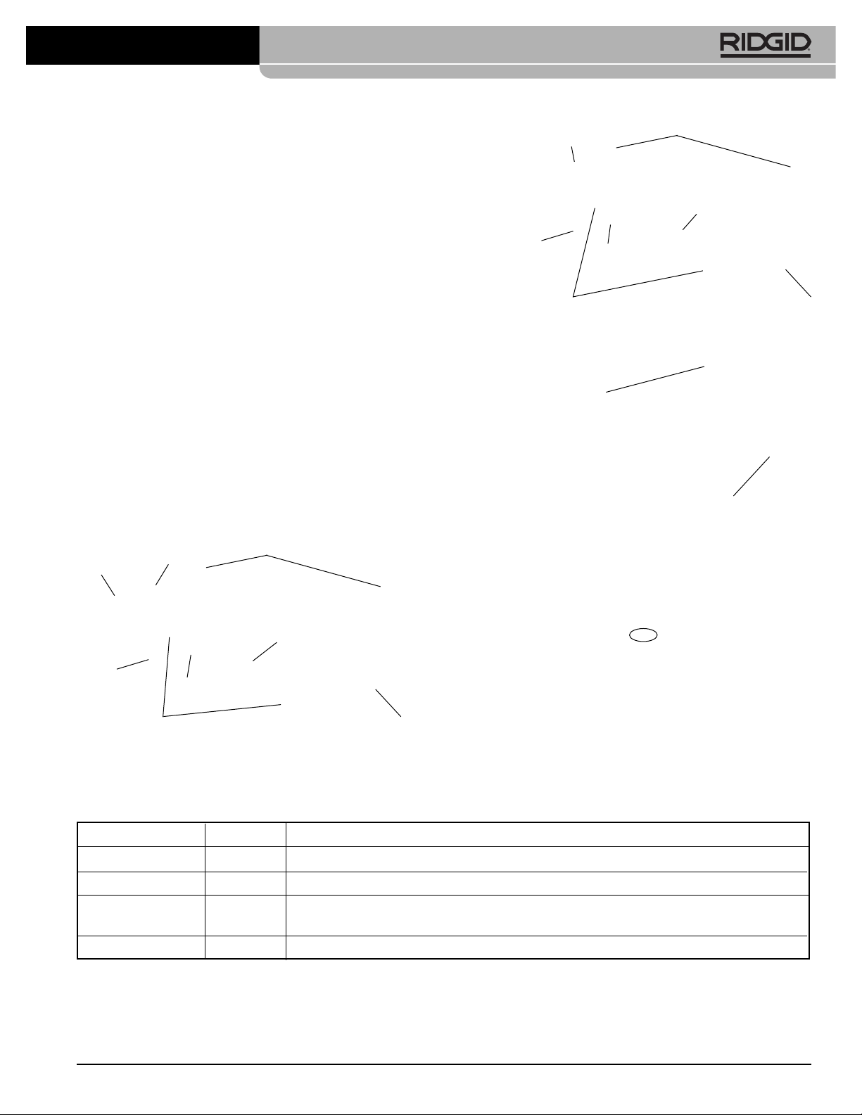
Fabric Loop
QCS Sleeve
QCS Type
Label
Loop
Pressure
Release
Button
LED Work
Light
Type Label
Switch
Warning Labels
Run
Figure 2 – RE 600 Series Dedicated Head Tools
LED
Figure 3 – Tool Status Lights
Battery
ON/OFF
Button
LED
Work
Light
Run
Switch
Pressure
Release
Button
Figure 4 – Machine Serial Number - The first 4 digits (cir-
Warning Labels
Battery
cled) indicate the year and month of manufacture. (12 = year, 06 = month).
Figure 1 – RE 6/RE 60 - Use QCS Coupling for head
attachment
Control Marking Description
On/Off Button
Run Switch — Depress to advance tool ram. In most cases, hold until ram automatically retracts.
Pressure — Allows tool ram retracted prior to automatic retraction. Primarily used with Punch Heads.
Release Button If used with a crimp head, crimp is NOT complete and must be repeated.
QCS Sleeve — Used to retract QCS balls and change heads.
Figure 5 – Controls Chart
I/O Main tool power switch (I = On, O = Off).
999-999-463.10_REV. H
Find Quality Products Online at: [email protected]
www.GlobalTestSupply.com
5
Page 8
RE 6/RE 60/RE 600 Electrical Tools
Green
Red
Yellow
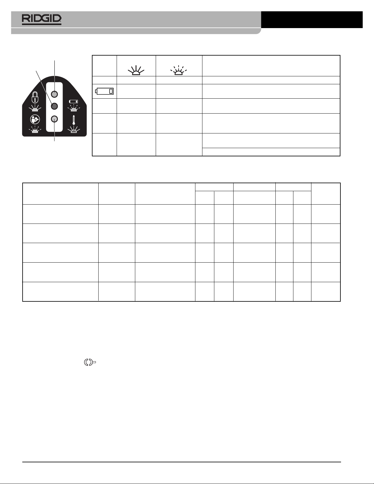
Figure 6 – Tool Status Lights
Specifications
Icon
Solid Light Blinking Light
Meaning
Green Tool ON, ready to use.
Green Battery low. Tool will not operate. Recharge
battery/Insert fully charged battery.
Red
Tool out of Specification temperature range. Bring tool
and battery to correct operating temperature range.
Indicates service interval approaching. Starts 2,000
Yellow
cycles prior to service interval (see Figure 7). Tool is
usable, but tool will lock after service interval.
Tool is locked. Tool has completed service interval
Yellow (see Figure 7) and requires service.
Tool has malfunctioned. Have serviced.
*
Model Description
Weight
g lbs
Dimensions Piston Travel Service
L x H x W (mm)
L x H x W (inch) Cycles
mm inch
RE 6 6T Tool For Use 3000 6.6 318 x 154 x 73 32 1.3 32,000
w/Interchangeable Heads 12.5 x 6.1 x 2.9
RE 60 60 kN Tool For Use 3000 6.6 318 x 154 x 73 32 1.3 32,000
w/Interchangeable Heads 12.5 x 6.1 x 2.9
Interval
RE 600 RDH Latching Round 4300*
1
9.5 395 x 165 x 73 17 0.7 32,000
Die Head 15.6 x 6.5 x 2.9
RE 600 SC Scissor Cut 4800 10.5 473 x 174 x 73 24 0.9 32,000
Head*
2
18.6 x 6.9 x 2.9
RE 600 4PI 4 PIN Indenter 5300 11.7 474 x 192 x 73 32 1.3 32,000
Head 18.7 x 7.6 x 2.9
*
With 2 Ah Battery *1Includes dies *2Versions for Cu/Al wire and ACSR available - See blade markings.
Figure 7 – Specification Chart
Piston Force ...............60 kN (6-ton) (13,500 lbs.)
QCS Coupling Type ...RE 6 6T QCS
RE 60 60 kN QCS
RE 600 Series – N/A
Duty Cycle.................. 3 Cycles per minute
Motor
Voltage ...................18V DC
Amperage ...............18 Amp
Power .....................324 Watts
Battery........................18V Li-Ion, Rechargeable Batter y
(see Optional Equipment)
Ingress Protection .......IP32
Allowable Humidity......0-80%
Operating Temperature
Range ...........................15° F to 122° F (-10° C to 50° C)
Storage Temperature
Range ...........................32° F to 113° F (0° C to 45° C)
Sound Pressure (L
PA
)* ...65 dB(A), K=3
Sound Power (LWA)*.......76 dB(A), K=3
Vibration*.......................<2.5 m/s2, K=1.5
* Sound and Vibration measurements are measured in accordance with a stan-
dardized test per Standard EN 62481-1.
- Vibration levels may be used for comparison with other tools and for preliminary assessment of exposure.
- Sound and vibration emissions may vary due to your location and specific use
of these tools.
- Daily exposure levels for sound and vibration need to be evaluated for each
application and appropriate safety measures taken when needed. Evaluation
of exposure levels should consider the time a tool is switched off and not in
use. This may significantly reduce the exposure level over the total working
period.
Go to RIDGID.com/CrimpDies for the RIDGID Crimp
6
Find Quality Products Online at: [email protected]
www.GlobalTestSupply.com
999-999-463.10_REV. H
Page 9
RE 6/RE 60/RE 600 Electrical Tools
Die/Electrical Connector Compatibility Charts for these
tools with various heads.
Standard Equipment
Refer to the RIDGID catalog for details on equipment
supplied with specific tool catalog numbers.
NOTICE
Selection of appropriate materials and joining
methods is the responsibility of the system designer and/or
installer. Before any installation is attempted, careful evaluation of the specific service environment requirements
should be completed. Consult connector manufacturer
for selection information.
Pre-Operation Inspection
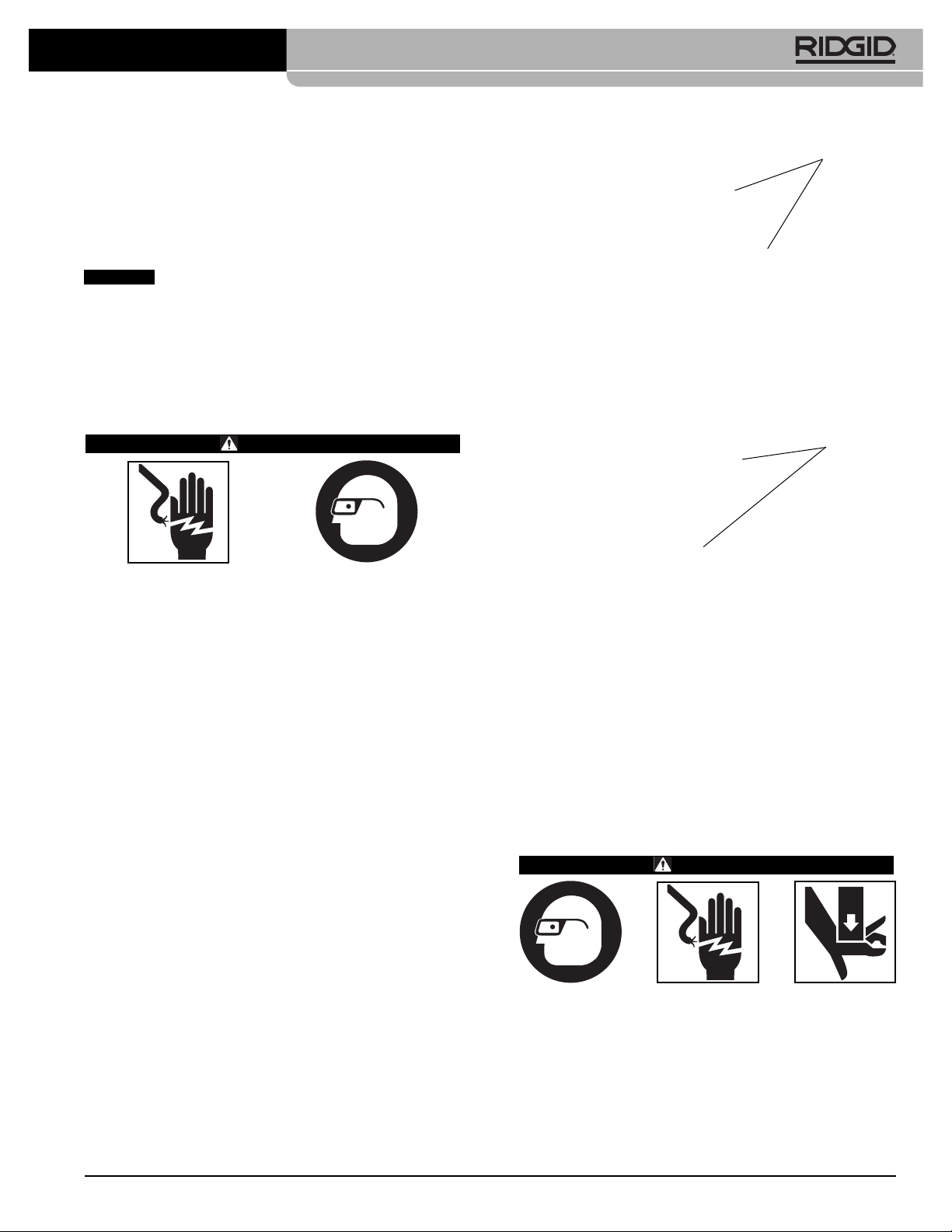
WARNING
Daily before use, inspect your electrical tool and cor rect any problems to reduce the risk of serious in jury
from electric shock, crushing injures, equipment
failure and other causes, and prevent tool damage.
Figure 8 – Inside of QCS Coupling
Figure 9 – Dimples in QCS Coupling Grooves
Retaining
Balls
Dimples
Acceptable
1. Remove battery from tool.
2. Clean any oil, grease or dirt from the tool and head,
including handles and controls. This aids inspection
and helps pre vent the tool or control from slipping from
your grip.
3. Inspect the electrical tool for:
• Proper assembly, maintenance and completeness
(See Figures 1-3).
• Any broken, worn, missing, misaligned or binding
parts.
• Presence and readability of the tool and battery
warning labels.
• Any other condition which may prevent safe and
normal operation.
If equipped with the QCS Coupling, inspect for:
• Foreign material in the QCS coupling (see Main -
tenance section).
• Confirm that all retaining balls are present in all
openings and that there is no damage. Figure 8
shows the inside of a complete and clean QCS
coupling.
• When inspecting the mating QCS coupling on
interchangeable heads, dimples in the grooves
of the QCS coupling are normal with use and are
not considered damage (Figure 9).
If any problems are found, do not use the tool until the
problems have been repaired.
4. Inspect and maintain any other equipment being used
per its instructions to make sure it is functioning properly. Inspect the heads for wear, deformation or other
issues.
Set-Up And Operating
Instructions
WARNING
Keep your fingers and hands away from the tool
head during the operating cycle. Your fingers or
hands can be crushed fractured or amputated in the
head or tool or be tween the tool head, work piece
and other objects.
Do not use on energized electrical lines to reduce
the risk of electrical shock, severe injury and death.
Tool is not insulated. Use appropriate work procedures and personal protective equipment when
working near energized electrical lines.
999-999-463.10_REV. H
Find Quality Products Online at: [email protected]
www.GlobalTestSupply.com
7
Page 10

RE 6/RE 60/RE 600 Electrical Tools
Large forces are generated during use that can
break or throw parts and cause injury. Keep all
unnecessary personnel away from work area. Stand
clear during use and wear appropriate protective
equipment, including eye protection.
Do not operate the electrical tool without inserts in
the tool head. This can damage the electrical tool
and/or cause serious personal injury.
Follow set up and operating instructions to reduce
the risk of injury from crushing, electrical shock
and other causes and to prevent tool damage.
1. Confirm have appropriate work area (See General
Safe ty Rules). Operate in clear, level, stable, dry loca-
tion. Do not use tool while standing in water.
2. Inspect the work to be done and determine the correct RIDGID tool for the application. Using an incorrect tool for an application can cause injury, damage
the tool and make incomplete connections.
3. Confirm that the electrical tool and head have been
inspected and set up as directed in their instructions.
If needed, confirm that proper dies have been in stalled in the head.
Changing Heads With QCS Coupling
(RE 6/RE 60 only)
Remove the battery from the tool. Retract QCS sleeve and
remove/insert the appropriate interchangeable head.
Release QCS sleeve to retain the head (Figure 10).
Confirm that the head is fully inserted and locked into the
tool. Do not operate without an interchangeable head or
head inserts installed - this can damage the electrical
tool. If interchangeable head will not lock into QCS coupling, ensure ram is fully retracted by pressing the pressure release button.
There are different QCS coupling types. Make sure that
the tool and interchangeable head QCS coupling types are
compatible (as marked).
QCS Type
Marking
Insert Head
Depress
QCS Sleeve
Operation
1. With dry hands, install a fully charged battery into the
electrical tool. Press the ON/OFF button (Figure 3) to
power on the electrical tool. All three tool status will
blink once. Then, the green light should solidly illuminate indicating the tool is ready to operate (See Figure
6 for Tool Status Lights). The electrical tool will automatically turn OFF if left unused for 600 seconds.
Figure 11 – Tool in operation
2. Refer to the instructions for the head in use for specific
operating instructions. With hands clear of the head
and other moving parts, depress the Run Switch to
advance the tool ram and activate the head. The
advancement of the ram can be stopped at any point
by releasing the Run Switch. This allows final positioning of the head for cutting, punching or gripping
and positioning of connectors.
Unless otherwise stated in the specific head instructions, continue to press the Run Switch until the ram
automatically retracts. Automatic ram retraction indicates that the electrical tool has reached the appropriate force and the cycle is complete. This is required
to ensure the complete crimping of electrical connections.
If the ram does not fully retract, press the pressure
release button. If the pressure release button is
pressed while crimping an electrical connection, the
crimp is NOT complete and needs to be repeated.
3. When operation is complete, press the ON/OFF button to turn OFF and remove the battery.
Storage
Remove battery from tool. Store electrical tool and battery
in case. Avoid storing in extreme heat or cold. The elec-
Figure 10 – Installing Interchangeable Head in the QCS
Coupling
8
Find Quality Products Online at: [email protected]
www.GlobalTestSupply.com
trical tool will not turn ON if the tool or battery temperature
is outside of the specification range. This will be indicated
by a tool status light. (See Figure 6)
999-999-463.10_REV. H
Page 11
RE 6/RE 60/RE 600 Electrical Tools
WARNING
Store in a dry, secured area that is out of
reach of children and people unfamiliar with the Electric
Tool. The electrical tool is dangerous in the hands of
untrained users.
Maintenance Instructions
WARNING
Remove battery from tool before performing maintenance or making any adjustment.
Cleaning Tool
Wipe exterior of the electrical tool clean daily with a clean,
dry cloth.
Cleaning QCS Coupling
Point the QCS opening down and gently shake any debris
out. Visually inspect the QCS opening for any debris.
Cotton swabs can be used to wipe out debris. Do not let
material build up into the retaining ball pockets (Figure 8).
The QCS coupling is lubricated for life at the factory. Do
not add any lubricant to the QCS coupling,
Required Maintenance By RIDGID
Independent Service Center
The Electrical tool must be serviced at set intervals by a
RIDGID Independent Service Center to ensure proper
operation. This will be indicated by a tool status light (See
Figure 6). See Specifications for service interval.
Service And Repair
WARNING
Improper service or repair can make machine
unsafe to operate.
Service and repair on these Electrical Tools must be performed by an RIDGID Independent Crimp Tool Service
Cent er. Use only RIDGID service parts.
For information on your nearest RIDGID Independent
Service Center or any service or repair questions see
Contact Information section in this manual.
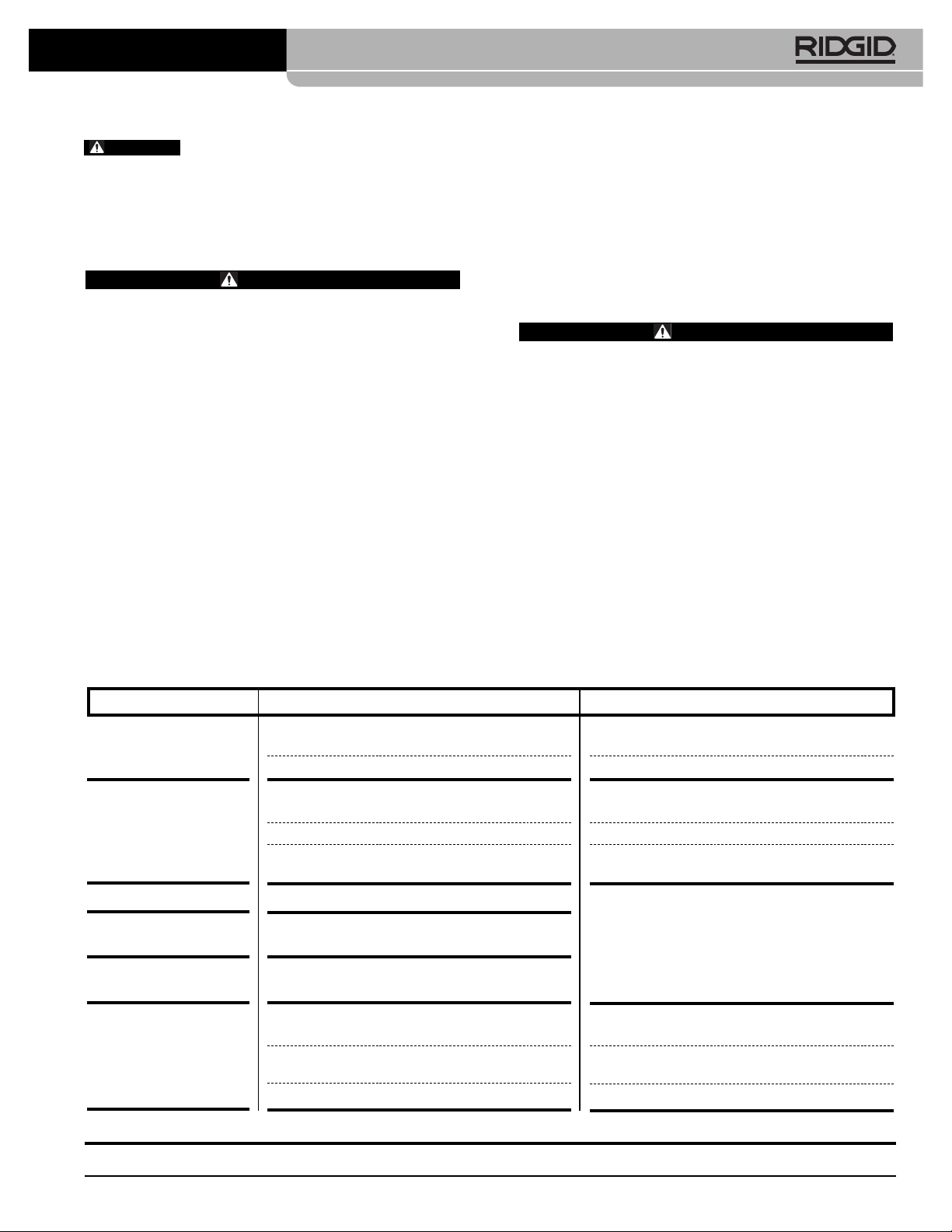
Troubleshooting
SYMPTOM POSSIBLE REASONS SOLUTION
Tool will not turn ON
when ON/OFF button is
pressed.
The connections
produced are not
complete.
Oil leaks from tool.
Motor runs but tool will
not complete a cycle.
Dies stop during
operation.
Cutting tool stops during operation.
Battery is completely discharged or battery has
failed.
Battery not properly inserted into handle of tool.
Used wrong tool/insert for the cable size or material.
The tool was not square to the connector.
Tool is in need of repair.
Seal or mechanical problems.
Oil level low.
Oil level low.
Oil Level low.
Cutting edges are dull or broken.
Material not within blade specification.
Insert fully charged battery/recharge battery.
Check to assure battery is fully inserted.
Install the correct tool/insert.
Make sure that the tool is square to the connector.
See Contact Information for nearest RIDGID Inde pendent Service center.
See Contact Information for nearest RIDGID Inde pendent Service center.
See Contact Information for nearest RIDGID
Inde pendent Service center.
Replace dull or broken blades with appropriate
replacements.
Change to blade specified for material to be cut.
See Figure 6 – Tool Status Lights
999-999-463.10_REV. H
Find Quality Products Online at: [email protected]
www.GlobalTestSupply.com
9
Page 12
RE 6/RE 60/RE 600 Electrical Tools
Optional Equipment
WARNING
To reduce the risk of serious injury, only use equipment specifically designed and recommended for
use with the RIDGID Electrical Tools, such as listed
below.
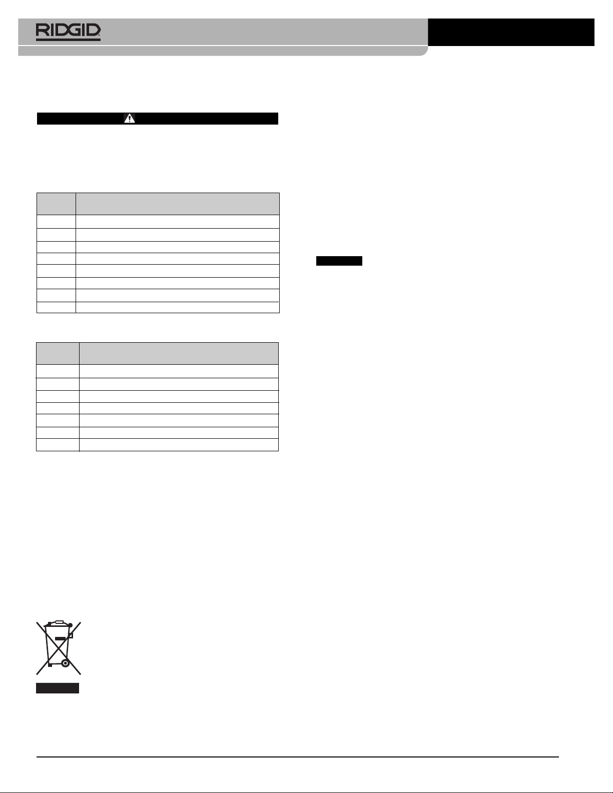
RE 6/RE 60/RE 600 Series
Catalog
No. Description
44693 18V 2.0Ah Battery (North & Latin America, Australia)
44698 18V 4.0Ah Battery (North & Latin America, Australia)
43458 120V Advanced Lithium Battery Charger
43333 230V Advanced Lithium Battery Charger
43323 18V 2.0Ah Battery (Europe & China)
43328 18V 4.0Ah Battery (Europe & China)
RE 6/RE 60 Series
Catalog
No. Description
52283 4P-6 4PIN™ Dieless Crimp Head
52078 Swiv-L-Punch Knockout Punch Head
47918 SC-60C Cutter Head for Copper/Aluminum Wire
49408 SC-60C Cutter Head for ACSR
52083 RE 6 Carrying Case (Plastic)
47773 RE 60 Carrying Case (Plastic)
47753 LR-60B Latching Round Head
Electromagnetic Compatibility
(EMC)
The term electromagnetic compatibility is taken to mean
the capability of the product to function smoothly in an
environment where electromagnetic radiation and electrostatic discharges are present and without causing
electromagnet interference to other equipment.
The RIDGID RE 6/RE 60/RE 600 Family of Electrical
Tools conform to IEC61000-6-5 (Ed. 1.0) Electromagnetic
Compatibility (EMC) Part 6-5: Generic Standards – Im munity for Equipment Used in Power Station and Sub station Environment.
NOTICE
standards. However, the possibility of them causing interference in other devices cannot be precluded. All EMC
related standards that have been tested are called out in
the tool's technical document.
These tools conform to all applicable EMC
For a complete listing of RIDGID equipment available
for these tools, see the Ridge Tool Catalog online at
RIDGID.com or see Contact Information.
Disposal
Parts of the Electrical Tool contain valuable materials
and can be recycled. There are companies that specialize
in recycling that may be found locally. Dispose of the
com ponents in compliance with all applicable regulations. Contact your local waste management authority
for more information.
For EC Countries: Do not dispose of electrical equipment with household waste!
According to the European Guideline 2012/ 19/ EU for Waste Electrical and Electronic
Equipment and its implemen tation into nation-
al legislation, electrical equipment that is no
longer usable must be collected separately and disposed
of in an environmentally correct manner.
10
Find Quality Products Online at: [email protected]
www.GlobalTestSupply.com
999-999-463.10_REV. H
 Loading...