

Page 1
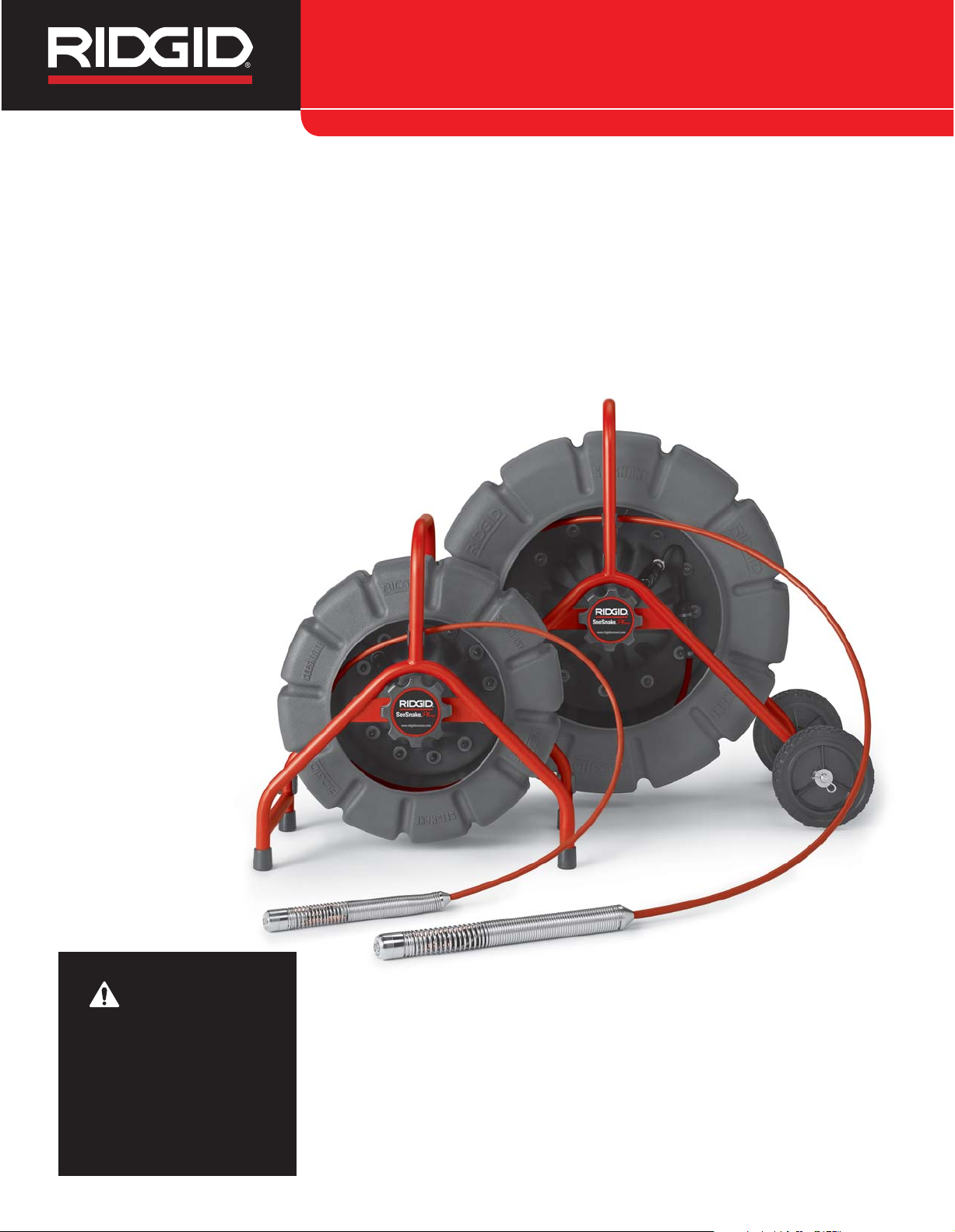
SeeSnake
®
Standard and
Mini Pipe Inspection
Systems
• Français – 21
• Castellano – pág. 43
SeeSnak e
®
Operator’s Manual
WARNING!
Read this Operator’s Manual
carefully before using this
tool. Failure to understand
and follow the contents of
this manual may result in
electrical shock, fire and/or
serious personal injury.
Find Quality Products Online at: [email protected]
www.GlobalTestSupply.com
Page 2

Ridge Tool Company
ii
Table of Contents
Recording Form for Machine Serial Number..............................................................................................................1
Safety Symbols..............................................................................................................................................................2
General Safety Rules
Work Area Safety........................................................................................................................................................2
Electrical Safety ..........................................................................................................................................................2
Personal Safety ..........................................................................................................................................................2
Equipment Use and Care............................................................................................................................................3
Service........................................................................................................................................................................3
Specific Safety Information..........................................................................................................................................3
SeeSnake Inspection System Product Safety ............................................................................................................3
Description, Specifications and Standard Equipment
Description..................................................................................................................................................................4
Specifications..............................................................................................................................................................4
Standard Equipment ..................................................................................................................................................5
SeeSnake System Components ..................................................................................................................................5
Description of the Components ..................................................................................................................................6
Camera Control Unit (CCU)........................................................................................................................................6
Locating System ........................................................................................................................................................6
Assembly
Installing the SeeSnake Wheels (Standard Unit Only) ..............................................................................................7
Installing Pipe Centering Guides ................................................................................................................................7
Installing Star Guides..................................................................................................................................................7
Installing Ball Guides ..................................................................................................................................................8
Installing the Roller Dolly ............................................................................................................................................9
Pre-Operation Inspection ............................................................................................................................................9
Work Area and Equipment Set Up ............................................................................................................................10
Positioning ................................................................................................................................................................10
Connections..............................................................................................................................................................10
Mechanical Checks ..................................................................................................................................................11
Electrical Checks ......................................................................................................................................................11
Count
Plus
Settings ..................................................................................................................................................11
Operating Instructions................................................................................................................................................12
Retrieving The Camera ............................................................................................................................................12
Using The Count
Plus
................................................................................................................................................14
Locating the Sonde ....................................................................................................................................................15
Retrieving The Camera ..............................................................................................................................................15
Maintenance Instructions ..........................................................................................................................................16
Cleaning Instructions ................................................................................................................................................16
Camera Maintenance................................................................................................................................................16
Push Cable, Reel/Frame ..........................................................................................................................................18
Changing the Count
Plus
Battery ..............................................................................................................................18
Camera Control Unit ................................................................................................................................................18
Locating Faulty Components ....................................................................................................................................19
Accessories ................................................................................................................................................................19
Transport and Storage................................................................................................................................................19
Service and Repair......................................................................................................................................................19
Disposal ......................................................................................................................................................................19
Troubleshooting..........................................................................................................................................................20
Lifetime Warranty ........................................................................................................................................Back Cover
SeeSnake®Standard and Mini Pipe Inspection Systems
Find Quality Products Online at: [email protected]
www.GlobalTestSupply.com
Page 3
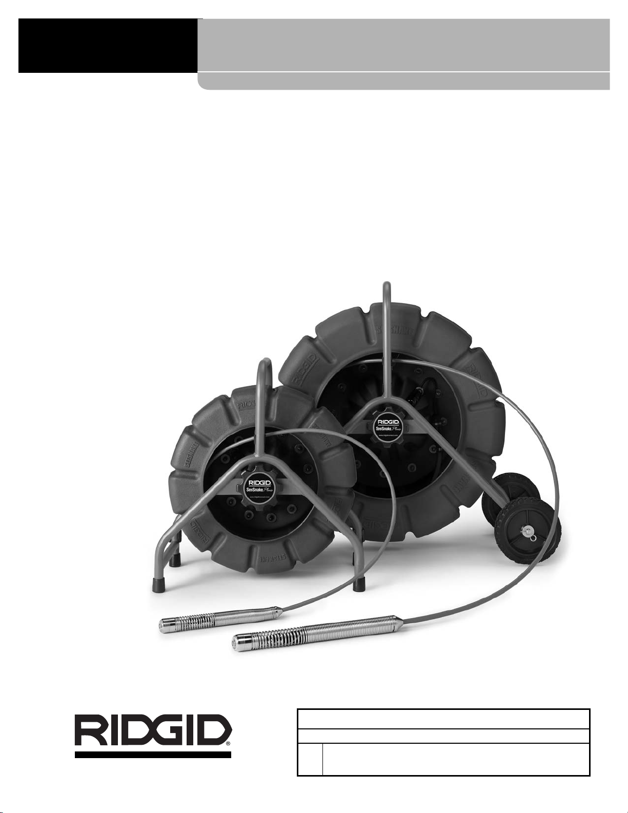
SeeSnake
®
Standard and Mini
Pipe Inspection Systems
SeeSnak e
®
SeeSnake®Standard and Mini
Record Serial Number below and retain product serial number which is located on nameplate.
Serial
No.
Find Quality Products Online at: [email protected]
www.GlobalTestSupply.com
Page 4
Ridge Tool Company
2
SeeSnake®Standard and Mini Pipe Inspection Systems
General Safety Rules
WARNING
Read all safety warnings and instructions. Failure to follow
the warnings and instructions may result in electric shock,
fire and/or serious injury.
SAVE THESE INSTRUCTIONS!
Work Area
• Keep work area clean and well lit. Cluttered or dark
areas invite accidents.
• Do not operate equipment in explosive atmo-
spheres, such as in the presence of flammable
liquids, gases, or dust. Equipment can create sparks
which may ignite the dust or fumes.
• Keep children and by-standers away while oper-
ating equipment. Distractions can cause you to lose
control.
Electrical Safety
• Do not operate the system or a camera control
unit with electrical components removed. Exposure
to internal parts increases the risk of injury.
• Avoid body contact with earthed or grounded sur-
faces such as pipes, radiators, ranges and refrigerators. There is an increased risk of electrical shock
if your body is earthed or grounded.
• Do not expose equipment to rain or wet condi-
tions. Water entering equipment will increase the risk
of electrical shock.
• If operating equipment in a damp location is un-
avoidable, use a ground fault circuit interrupter
(GFCI) protected supply. Use of a GFCI reduces
the risk of electric shock.
• Keep all electrical connections dry and off the
ground. Do not touch equipment or plugs with
wet hands. This reduces the risk of electrical shock.
Personal Safety
• Stay alert, watch what you are doing and use common sense when operating equipment. Do not
use equipment while you are tired or under the influence of drugs, alcohol or medication. A moment
of inattention while operating equipment may result in
serious personal injury.
• Use personal protective equipment. Always wear
eye protection. Protective equipment such as dust
mask, non-skid safety shoes, hard hat, or hearing
protection used for appropriate conditions will reduce
personal injuries.
• Do not overreach. Keep proper footing and balance
at all times. This enables better control of the equipment in unexpected situations.
Equipment Use and Care
• Do not force equipment. Use the correct equipment for your application. The correct equipment will
do the job better and safer at the rate for which it is designed.
Safety Symbols
In this operator’s manual and on the product, safety symbols and signal words are used to communicate important safety
information. This section is provided to improve understanding of these signal words and symbols.
This is the safety alert symbol. It is used to alert you to potential personal injury hazards. Obey all safety messages that follow this
symbol to avoid possible injury or death.
DANGER indicates a hazardous situation which, if not avoided, will result in death or serious injury.
WARNING indicates a hazardous situation which, if not avoided, could result in death or serious injury.
CAUTION indicates a hazardous situation which, if not avoided, could result in minor or moderate injury.
NOTICE indicates information that relates to the protection of property.
This symbol means read the operator’s manual carefully before using the equipment. The operator’s manual contains important
information on the safe and proper operation of the equipment.
This symbol means always wear safety glasses with side shields or goggles when handling or using this equipment to reduce
the risk of eye injury.
This symbol indicates the risk of electrical shock.
NOTICE
DANGER
WARNING
CAUTION
Find Quality Products Online at: [email protected]
www.GlobalTestSupply.com
Page 5

Ridge Tool Company
3
SeeSnake®Standard and Mini Pipe Inspection Systems
• Do not use equipment if the switch does not turn it
ON and OFF. Any equipment that cannot be con-
trolled with the switch is dangerous and must be repaired.
• Disconnect the plug from the power source and/or
the battery pack from the equipment before making
any adjustments, changing accessories or storing. Such preventive safety measures reduce the risk
of injury.
• Store idle equipment out of the reach of children
and do not allow persons unfamiliar with the equipment or these instructions to operate the equipment. Equipment can be dangerous in the hands of
untrained users.
• Maintain equipment. Check for misalignment or bind-
ing of moving parts, missing parts, breakage of parts
and any other condition that may affect the equipment’s operation. If damaged, have the equipment
repaired before use. Many accidents are caused by
poorly maintained equipment.
• Use the equipment and accessories in accordance
with these instructions, taking into account the
working conditions and the work to be performed.
Use of the equipment for operations different from
those intended could result in a hazardous situation.
• Use only accessories that are recommended by
the manufacturer for your equipment. Accessories
that may be suitable for one piece of equipment may
become hazardous when used with other equipment.
• Keep handles dry and clean; free from oil and
grease. Allows for better control of the equipment.
Service
• Have your equipment serviced by a qualified repair
person using only identical replacement parts. This
will ensure that the safety of the equipment is maintained.
Specific Safety Information
WARNING
This section contains important safety information
that is specific to this equipment.
Read these precautions carefully before using the
SeeSnake
®
Inspection System to reduce the risk of
electrical shock, fire or other serious personal injury.
SAVE THESE INSTRUCTIONS!
Keep this manual with the equipment for use by the operator.
SeeSnake Inspection System Product
Safety
• An improperly grounded electrical outlet can cause
electrical shock and or severely damage equipment. Always check work area for a properly grounded
electrical outlet. Presence of a three-prong or GFCI outlet does not insure that the outlet is properly grounded.
If in doubt, have the outlet inspected by a licensed electrician.
• Do not operate this equipment if operator or ma-
chine is standing in water. Operating machine while
in water increases the risk of electrical shock.
• The SeeSnake System camera and pushrod are
waterproof. The camera control unit and other
electrical equipment and connections are not. Do
not expose the equipment to water or rain. This increases the risk of electrical shock.
• Do not use where a danger of high voltage contact
is present. The equipment is not designed to provide high voltage protection and isolation.
• Read and understand this operator’s manual, the
monitor operators’ manual and the instructions
for any other equipment in use before operating
the SeeSnake System. Failure to follow all instruction
may result in property damage and/or serious personal injury.
• Always use appropriate personal protective equip-
ment while handling and using equipment in drains.
Drains may contain chemicals, bacteria and other substances that may be toxic, infectious, cause burns or
other issues. Appropriate personal protective equipment always includes safety glasses, and may include
equipment such as drain cleaning gloves or mitts, latex
or rubber gloves, face shields, goggles, protective
clothing, respirators and steel-toed footwear.
• If using drain cleaning equipment at the same time
as using drain inspection equipment, wear RIDGID
Drain Cleaning Gloves. Never grasp the rotating
drain cleaning cable with anything else, including other
Find Quality Products Online at: [email protected]
www.GlobalTestSupply.com
Page 6

Ridge Tool Company
4
SeeSnake®Standard and Mini Pipe Inspection Systems
gloves or a rag. They can become wrapped around the
cable, causing hand injuries. Only wear latex or rubber
gloves under RIDGID Drain Cleaner Gloves. Do not
use damaged drain cleaning gloves.
• Practice good hygiene. Use hot, soapy water to
wash hands and other exposed body parts exposed to
drain contents after handling or using drain inspection
equipment. Do not eat or smoke while operating or
handling drain inspection equipment. This will help
prevent contamination with toxic or infectious material.
• Turn OFF camera when not in use. This will prolong
the unit’s life and avoid excessive heat buildup.
Description, Specifications
And Standard Equipment
Description
The RIDGID®SeeSnake®Pipe Inspection system is a
durable reel and camera system that helps you diagnose and locate problems in drain and sewer systems.
The SeeSnake family of diagnostic equipment includes
Standard and Mini reels and camera heads, a choice of
camera control, video display and recording options and
a locating system to help you quickly pinpoint problems
underground. Every component in the SeeSnake system has been engineered and tested to ensure rugged
and reliable operation on the kinds of jobs you encounter
every day. SeeSnake Pipe Inspection Cameras are ideal
for inspecting 2" to 12" (Standard SeeSnake) and 1.5" to
8" (Mini SeeSnake) drain lines. Their flexible camera
heads can negotiate multiple hard 90° bends. The fiberglass-reinforced pushrod is flexible enough to easily travel
through bends, yet stiff enough to push the camera head
up to 325' (Standard SeeSnake) and 200' (Mini SeeSnake). The scene as viewed by the camera is transmitted to a viewing screen and may be recorded to DVD,
VCR, SD or USB storage device, depending on the
Camera Control Unit employed.
A self-leveling camera head is also available on the
Standard SeeSnake to help keep the image upright for the
viewer.
The Count
Plus
component enables the display of real-time
distance measurement and custom text overlays on the
video screen which can also be recorded with the video as
an overlay.
Specifications
Available Cable Lengths:
Mini SeeSnake ............200' (61 m)
Standard SeeSnake ....200' (61 m) and 325' (99 m)
Reel & Frame Weight:
Mini SeeSnake ............24.5 lbs. (11.1 Kg) with 200'
cable
Standard SeeSnake ....42 lbs. (19 Kg) with 200' cable
53 lbs. (24 Kg) with 325' cable
Reel & Frame Dimensions:
Mini SeeSnake ............20 x 11 x 23 in.
(51 x 28 x 58 cm)
Standard SeeSnake ....32 x 14 x 30 in.
(81 x 36 x 76 cm)
Power Source................120V/60 Hz, 230V/50 Hz, or
14-16VDC, depending on CCU
Pushrod Diameter .........Mini SeeSnake: 0.315"
(0.8 cm)
Standard SeeSnake: 0.43"
(1.1 cm)
Camera Type.................NTSC/PAL (color) video format
Camera Size & Weight:
Mini SeeSnake .............1.66 x 1.18 in., 2.5 oz.
(42 mm x 30 mm, 69 g)
Standard SeeSnake ....1.80 x 1.38 in., 4.2 oz.
(46 mm x 35 mm, 113 g)
Depth Rating .................Cameras waterproof to 330'
(100 m)
Camera Resolution:
Lighting:
Mini SeeSnake ............6 white high-power LED’s
SeeSnake....................6 white high-power LED’s
Operating Environment:
Temperature................32°F to 104°F (0°C to 40°)
Altitude ........................Up to 6560 ft.(2000 m)
Transient Over
Voltage.........................Installation Categories II
(1500V phase to Earth)
Pollution Degree 2
SeeSnake Pipe Inspection Systems are protected under
one or more of the following patents: 5,457,288, 5,808,239,
5,939,679, 6,545,704, 6,831,679, 6,697,102, 6,958,767,
6,862,945, 6,908,310 and other patents pending.
Standard Equipment
• Camera Reel with Pushrod
• Camera Head
• Count
Plus
• Centering Guides (standard star, ball-type and Roller
Dolly) and C-Rings (for holding Star Guides onto
spring assembly)
Color camera...............656 x 492 NTS
C/768 x 576 PAL
Find Quality Products Online at: [email protected]
www.GlobalTestSupply.com
Page 7
Ridge Tool Company
5
SeeSnake®Standard and Mini Pipe Inspection Systems
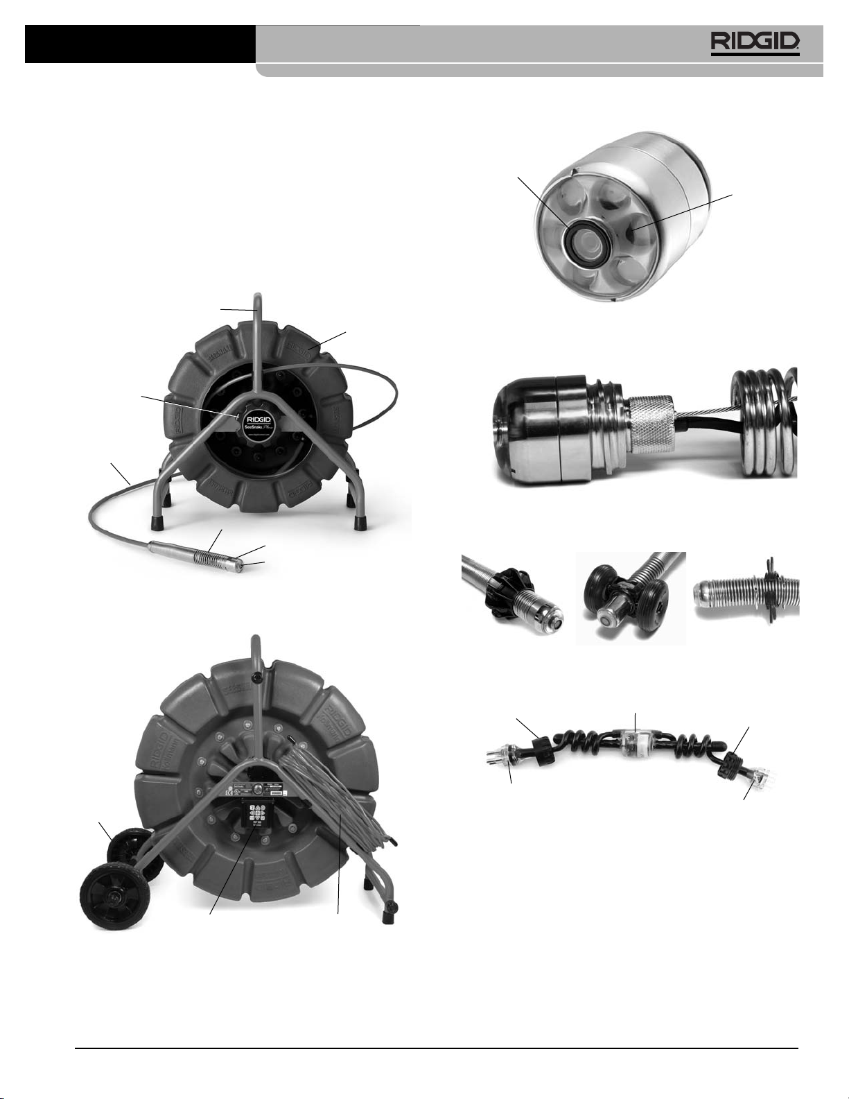
Figure 1 – SeeSnake System Left Side View
SeeSnake System Components
Frame
Drum
Brake
Pushrod
Camera Housing
Spring Assembly
Figure 2 – SeeSnake System Right Side View
Count
Plus
Wheels
System Cable
Figure 3 – Camera Head
Sapphire
Window
LED Ring
• SeeSnake System Cable
• Universal Spanner Wrench (for Camera Head Removal)
• SeeSnake Instructional DVD
• Operator’s Manual for Reel and Count
Plus
Camera Head
Figure 4 – Camera Head and Locking Sleeve
Figure 5 – Centering Guides and Roller Dolly
Figure 6 – Flexmitter
Male Connector
Flexmitter
Assembly
Female In-Line
Locking Sleeve
Female Connector
Male In-Line
Locking Sleeve
Find Quality Products Online at: [email protected]
www.GlobalTestSupply.com
Page 8
Camera Control Unit (CCU)
Be sure you are familiar with the camera control unit
of your system and have read its operator’s manual
carefully.
The CCU provides power to the camera reel and system
accessories. It also provides a control that adjusts the
camera’s lighting and activates the in-line transmitter, or
Sonde.
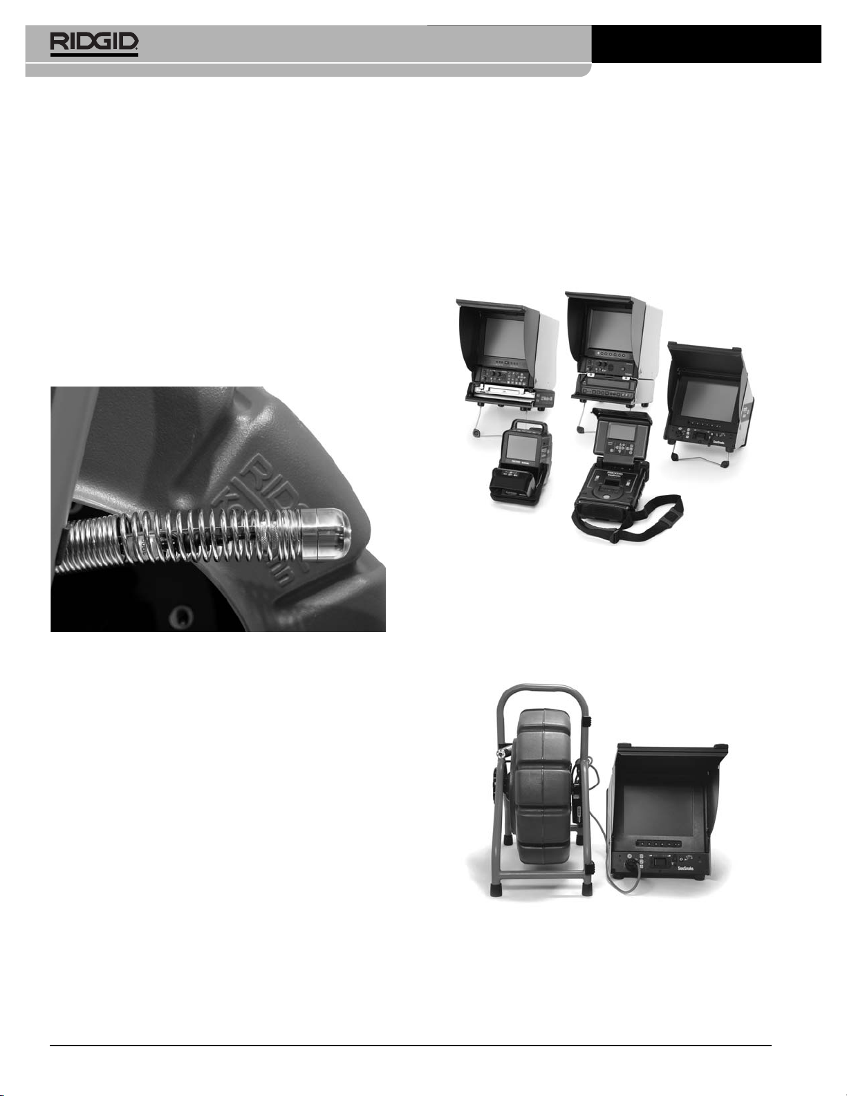
Figure 8 – SeeSnake CCUs
Camera Control Units come in many convenient sizes and
configurations, from a hand-carried MINI
Pak
unit to color
monitors with audio and digital video recording capability.
Units may be powered by a 120/220 volt AC source or
12VDC and some include rechargeable batteries.
Figure 9 – SeeSnake With LCD
Pak
CCU
Locating System
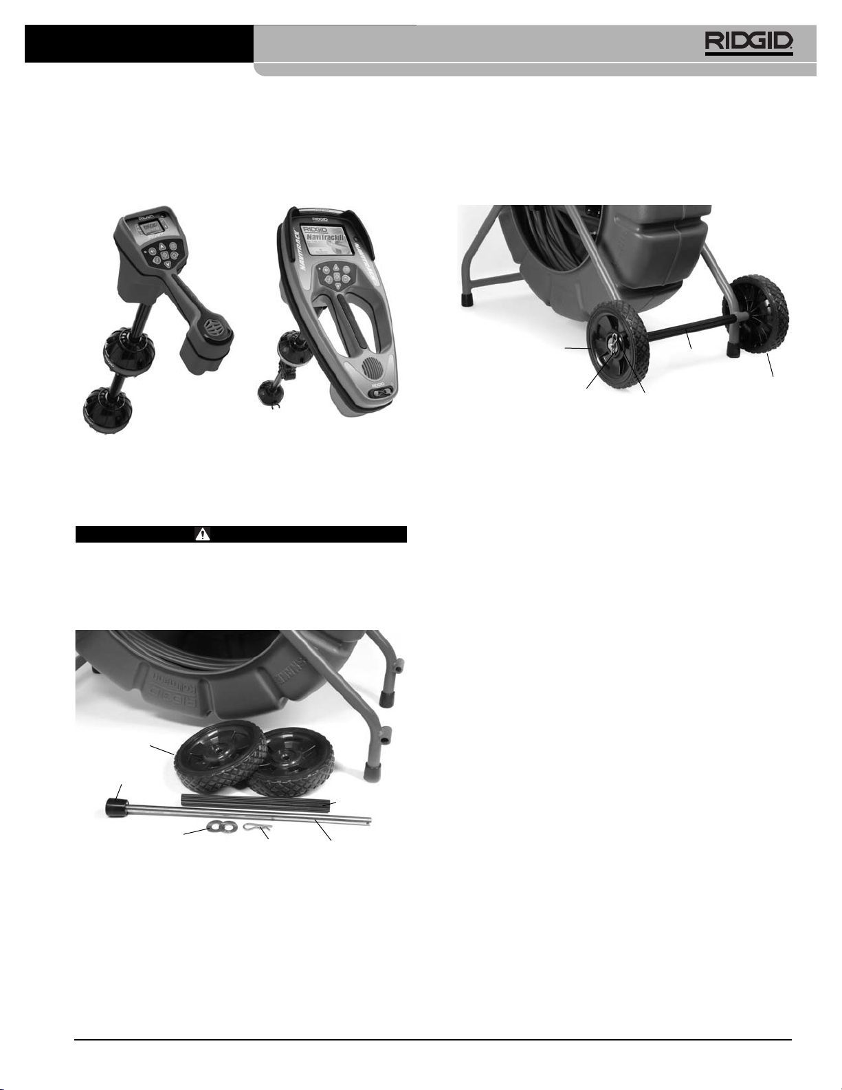
The transmitter built into modern SeeSnake units allows
the operator to use a hand-held locator to pinpoint the location of the camera head in the pipe from above ground.
Description of the Components
The SeeSnake Pipe Inspection System includes four
sub-assemblies: the camera head, the reel and frame, the
Camera Control Unit and a locating system.
The camera head has adjustable lighting elements and an
advanced-design, scratch-resistant sapphire window
(Lens Port). This, coupled with the stainless steel armoring, allows the camera to withstand repeated stresses and
impacts in cast iron pipes. A polycarbonate ring covers
and protects multiple LED light sources.
A flexible stainless steel spring assembly holds the camera to the pushrod. It provides a flexible transition from
camera to pushrod, and protects the electrical connections
within the spring.
Figure 7 – Spring Assembly and Camera Head
Modern SeeSnake systems are shipped with a built-in
Flexmitter transmitter (Sonde) which enables an operator
to pinpoint the location of a camera in a line from above
ground.
The pushrod is stored in a molded drum, which is rust and
dent-proof and keeps waste water off your customers’ carpets. Slip rings inside the drum’s hub provide a rotating
electrical connection between the drum and frame and
allow operation at any angle.
A sturdy, coated metal frame supports the reel. The
frame has a second set of feet on the back side of the reel,
allowing the system to rest on its back (open-end-up)
for greater stability.
The Count
Plus
measures the distance the cable has
traveled inside the pipe and can also display the day, date,
time and add overlays of user-defined text information. The
Count
Plus
also allows you to measure a custom dis-
tance from any starting point in the line.
Ridge Tool Company
6
SeeSnake®Standard and Mini Pipe Inspection Systems
Find Quality Products Online at: [email protected]
www.GlobalTestSupply.com
Page 9
Ridge Tool Company
7
SeeSnake®Standard and Mini Pipe Inspection Systems
The transmitters operate at the industry-standard of
512Hz, are extremely durable, require no batteries for operation and are flexible so they do not interfere with camera’s ability to go through turns.
Figure 10 – Scout®and NaviTrack®Locators
Assembly
WARNING
To reduce the risk of serious injury during use, follow
these procedures for proper assembly.
Installing the SeeSnake Wheels
(Standard unit only)
Figure 11 – Wheel and Axle Assembly Components
1. Slide washer onto axle and seat against foot.
2. Slide wheel onto axle with six spokes facing inward.
3. Place ribbed rigid tube between the two axle hubs.
Frame may need to be flexed slightly. Slide axle
from outside right, through hub and rigid tube and out
the other hub.
4. Place second wheel on axle with six spokes facing inward.
5. Place washer on axle and seat on wheel hub. Secure
w/cotter pin at axle end.
Figure 12 – Wheel and Axle Assembly (Washer and Foot
Not Shown)
Installing Pipe Centering Guides
Pipe centering guides are designed to help center the
camera in pipes of various sizes, and keep the camera
clear of bottom sludge in the pipe. By bringing the camera
closer to the center of the pipe they improve picture quality, allowing the camera to see equally in all directions and
keeping the camera lens clear during inspections.
Centering guides should generally be used when possible, because they reduce wear and tear on the camera
system. If you run into difficulty moving the camera
through a particular pipe, the centering guides can be
easily removed. The placement of the guides can be adjusted to best suit the job. For example, you may find that
placing two centering guides near the front end of the
camera may bias the camera head upward. This could
be beneficial if you need to see the top of the pipe during your inspection.
There are three kinds of centering guides available for
SeeSnake systems. They are:
a. Star Guides
b. Ball Guides
c. Roller-Dolly (Standard only)
The type of centering guide you choose depends on the
diameter and complexity of the pipe line you are going to
inspect.
Installing Star Guides
Star guides support the camera head through the use of
vanes extending out from the center ring. They are held
in place with C-shaped clip-rings.
Foot
Ribbed
Rigid Tube
Axle
Cotter Pin
Washers
Ribbed Rigid
Tube and
Axle
Wheel
Cotter Pin
Washer
Wheel
Wheels
Find Quality Products Online at: [email protected]
www.GlobalTestSupply.com
Page 10
Ridge Tool Company
8
SeeSnake®microDrain™ Inspection Systems
1. Select the size of star guide appropriate for the job.
Star guides may be trimmed by cutting the individual
vanes with scissors.
2. Lay out two or three star guides next to their C-rings.
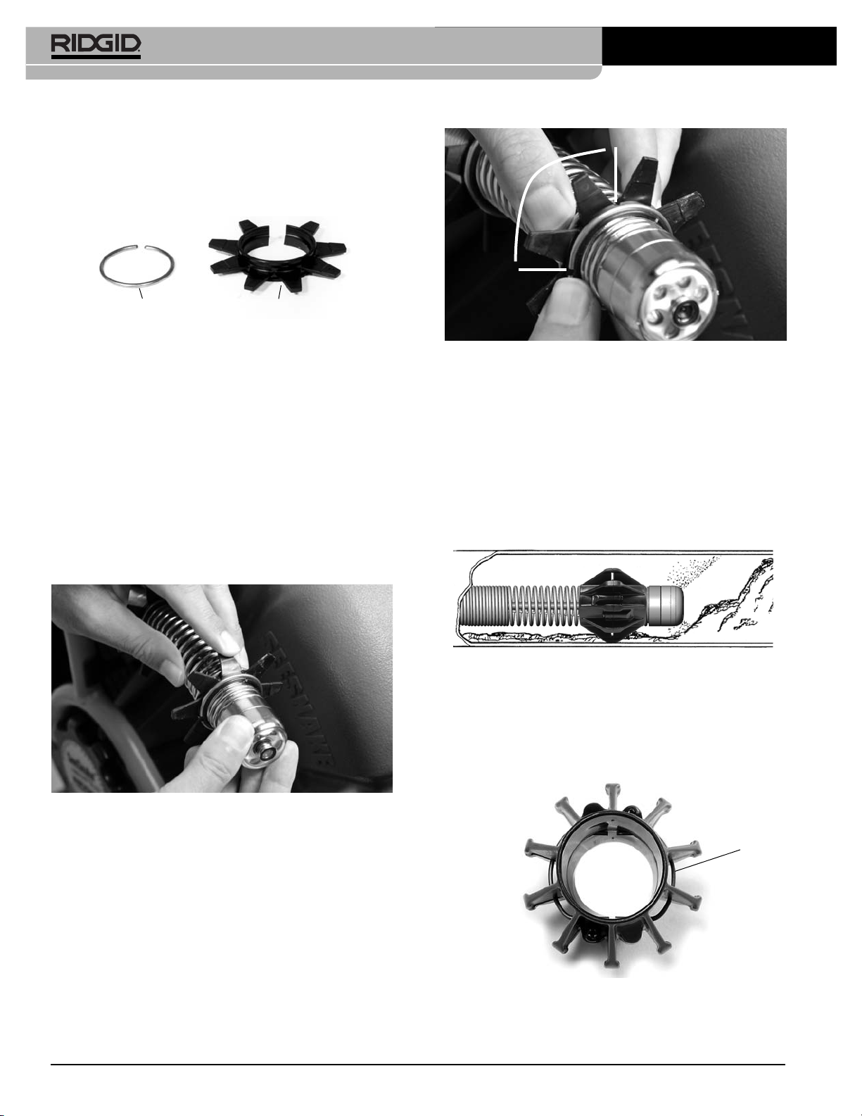
Figure 13 – Star Guide and C-Ring
3. Spread the C-ring open just enough to slip it over the
hub of the star guide. Align the C-ring gap with the
gap in the star guide. Press the C-ring into the
grooved portion of the hub. Repeat with the second
C-Ring for the opposite side of the hub.
4. Spread the star guide and C-rings together and slide
over the camera head, or around the cable and up
from the camera base, to the desired position on
the spring and release.
5. Pre-stressing the vanes of the star-guide will help
make them more flexible in use. Bend each vane gently back and forth several times to pre-stress them.
Figure 14 – Pre-stressing The Flanges
6. Once the star guide is installed, it will help to prevent
loss if you adjust the C-ring so that the gap is at
least 90 degrees from the star guide’s gap.
Figure 15 – Separate The Gaps By 90°
7. Removing Star Guides: Slide the end of a flat-
tipped screwdriver between the C-ring and the base
of the vane. Pry or snap the C-ring off. Repeat for the
second C-ring and slide the rings and the star guide
off the cable.
Installing Ball Guides
Ball-type centering guides use two retaining rings that
hold the guide in place on the spring.
Figure 16 – Camera With Ball Guide In Use
To unlock the retaining rings, pull them outward with the
tip of a flat-tipped screwdriver. You will then be able to
slide the ball guide over the camera head and position it.
Lock the rings by pressing them in once the guide is in
position.
Figure 17 – Retaining Rings Locked
C-Ring
Star Guide
90° or more
Retaining
Rings Locked
Find Quality Products Online at: [email protected]
www.GlobalTestSupply.com
Page 11
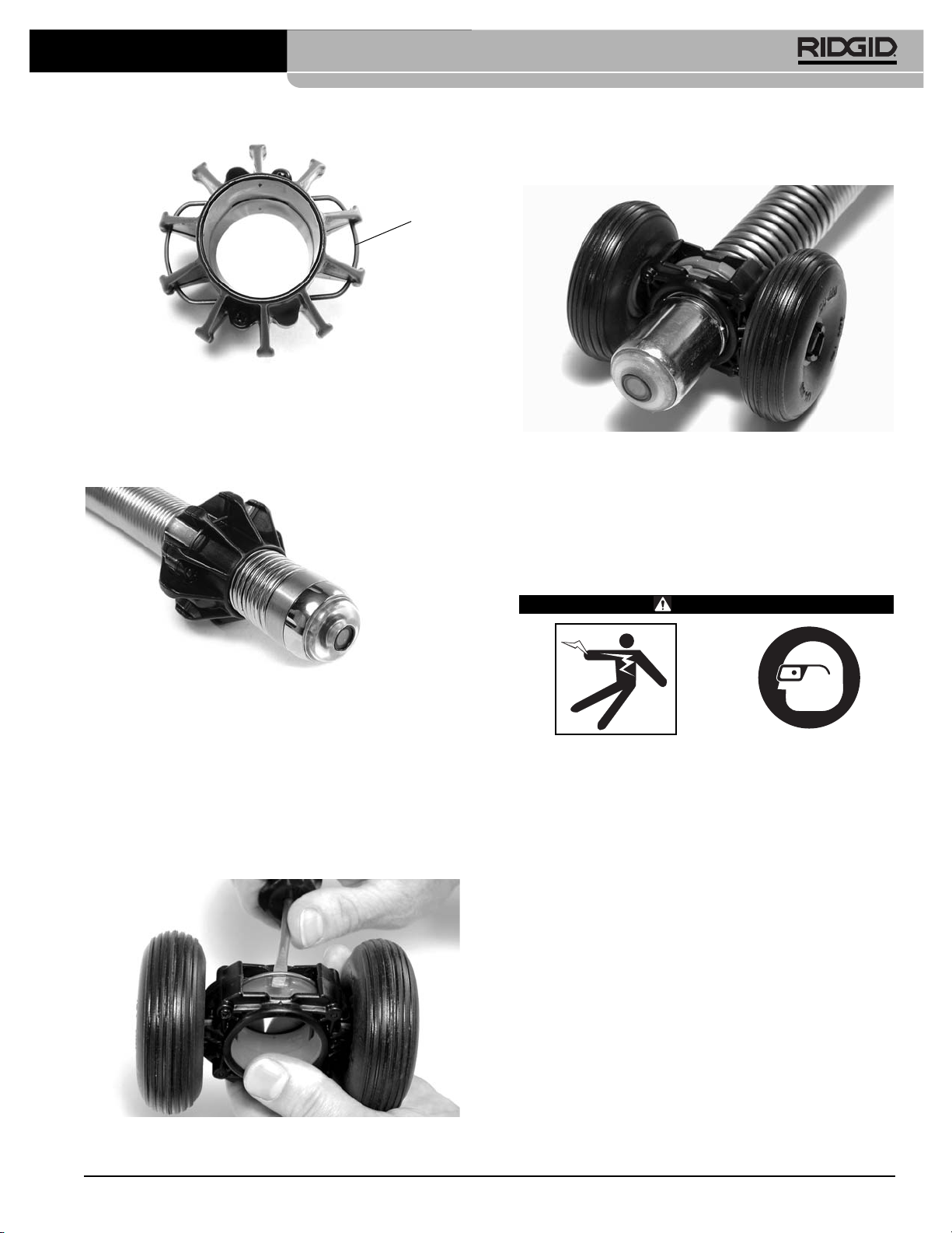
Slide the Roller Dolly over the camera head to the desired
position and press the retaining rings closed.
Figure 21 – Roller Dolly Installed
To remove the Roller Dolly, use the tip of a flat-tipped
screwdriver to lift the retaining rings to their open position
and slide the guide off the spring assembly.
Pre-Operation Inspection
WARNING
Before each use, inspect your SeeSnake System
camera and reel and correct any problems to reduce
the risk of serious injury from electrical shock or
other causes and prevent machine damage.
1. With the SeeSnake unplugged from the camera control unit, inspect the system cable and plug for damage or modifications. If any damage or modification is
found, do not use the tool until it has been properly repaired or replaced.
2. Clean any dirt, oil or other contamination from the
SeeSnake, especially from the frame, to prevent the
unit from slipping from your grip while transporting or
using.
3. Inspect the SeeSnake for any broken, worn or missing, misaligned or binding parts, or any other condition
which might prevent safe, normal operation. Confirm
that the unit is properly assembled. Make sure the
cable drum rotates freely and the drum brake works
correctly.
Ridge Tool Company
9
SeeSnake®microDrain™ Inspection Systems
Figure 18 – Retaining Rings Unlocked
NOTE! Spring must not be over tightened on the
camera head. Over tightening will cause the
end closest to the camera head to rise, and
may prevent the ball guide from sliding onto
the spring.
Figure 19 – Slide Ball Guide Over Spring and Lock
Retaining Rings
Installing the Roller Dolly
For larger pipes (4.5" or larger) using the Standard
SeeSnake, you can also choose to use the Roller Dolly
guide. The Roller Dolly guide is especially useful for long
straight inspections such as in city service lines.
To install the Roller Dolly, open the top and bottom retaining rings on the guide using a flat-tipped screwdriver.
Figure 20 – Opening The Roller Dolly Retaining Rings
Retaining
Rings
Unlocked
Find Quality Products Online at: [email protected]
www.GlobalTestSupply.com
Page 12
Ridge Tool Company
10
SeeSnake®Standard and Mini Pipe Inspection Systems
4. Visually inspect the pushrod for cuts and abrasions. If
the outer jacket is cut or abraded through, the cable
should be replaced or repaired (re-terminated).
5. Inspect any other equipment being used per its instructions to make sure it is in good usable condition.
6. If any problems are found, do not use the unit until the
problems are corrected.
Work Area and Equipment
Set Up
WARNING
Set up the SeeSnake System and work area according to these procedures to reduce the risk of injury from electrical shock, fire and other causes,
and to prevent damage to the SeeSnake System.
Always wear eye protection to protect your eyes
against dirt and other foreign objects.
1. Check work area for:
• Adequate lighting.
• Flammable liquids, vapors or dust that may ignite.
If present, do not work in area until sources have
been identified and corrected. The SeeSnake
System is not explosion proof. Electrical connections can cause sparks.
• Clear, level, stable, dry place for machine and op-
erator. Do not use the machine while standing in water. If needed, remove the water from the work
area.
• Clear path to electrical outlet, if used for monitor,
that does not contain any potential sources of damage for the power cord.
2. Inspect the work to be done If possible, determine the
drain access point(s), size(s) and length(s), presence of drain cleaning chemicals or other chemicals,
etc. If chemicals are present, it is important to understand the specific safety measures required to work
around those chemicals. Contact the chemical manufacturer for required information.
If needed, remove fixture (water closet, sink, etc.) to
allow access.
3. Determine the correct equipment for the application.
The SeeSnake Standard System is made for:
• 2" to 12" lines up to 325' long.
The MINI System is made for:
• 1.5" to 8" lines up to 200' (61m) long.
4. Make sure all equipment has been properly inspected.
5. Evaluate the work area and determine if any barriers
are needed to keep bystanders away. Bystanders
can distract the operator during use. If working near
traffic, erect cones or other barriers to alert drivers.
Positioning
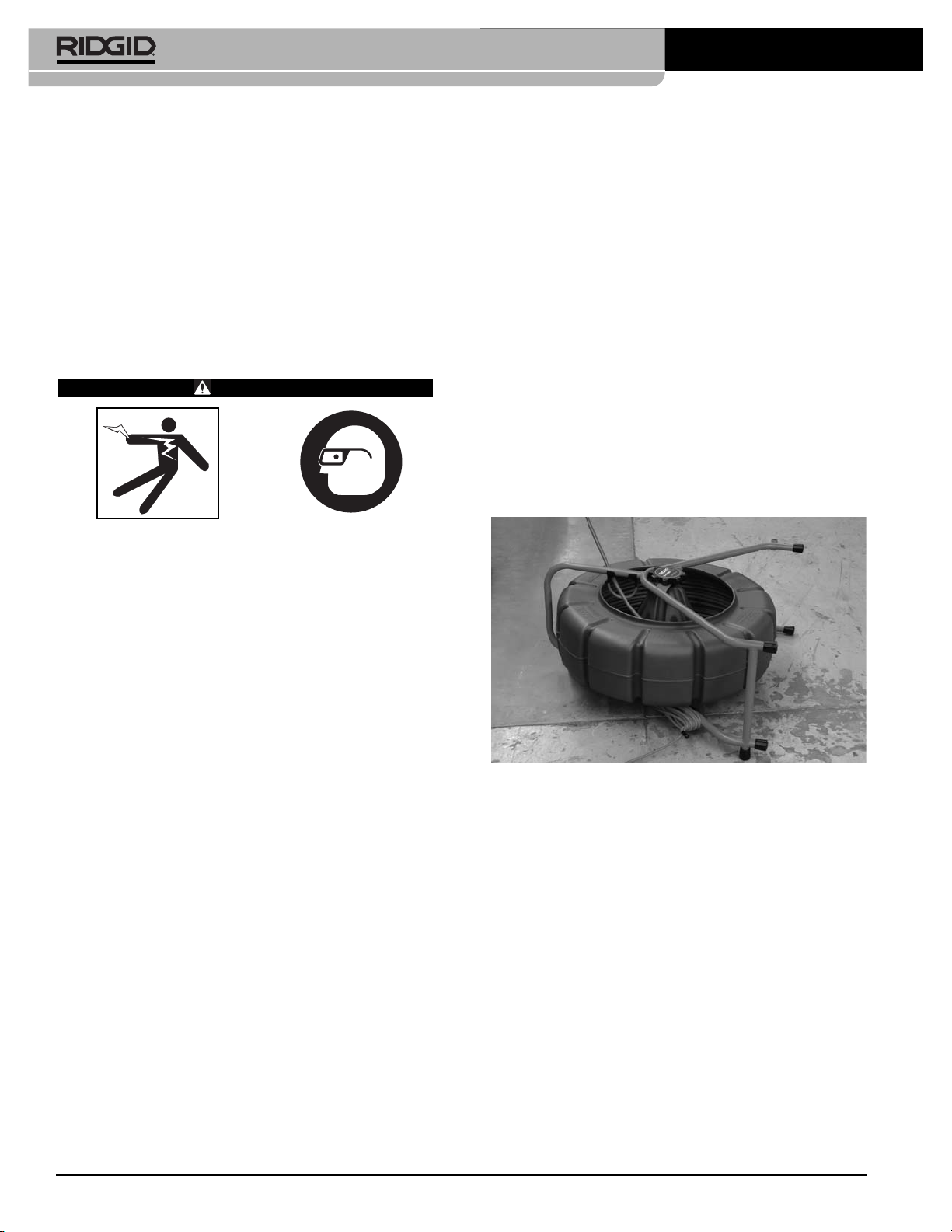
Properly positioning the equipment and pushing of the
cable will save time, be more comfortable and minimize the potential for equipment damage. You can lay
the system on its back supports for even greater stability. This is also preferred when on a rooftop (entry
through a roof vent), overhead entry or hillside.
Figure 22 – Reel Can Be Positioned On Its Back For
Greater Stability
Place the reel so the pushrod is easy to manage as you
push the camera through the line – about 3' to 5' (1-2 meters) from the entry. This will provide ample cable to
grasp and will develop momentum without having a lot of
slack dragging on the ground. Slack can be alleviated by
putting friction on the reel using the brake. Set up the
Camera Control Unit (CCU) in an area where it is stable
and can be viewed while you are pushing the camera.
The location should not be wet or allow the monitor to get
wet and should be close enough that its controls are
easy to reach during use. In brightly lit areas, point the
monitor screen away from bright light sources and/or
use the monitor’s sun shade to reduce glare.
Connections
1. Connect the Camera Control Unit to an AC outlet if
needed and press the reset button on the GFCI if provided.
Find Quality Products Online at: [email protected]
www.GlobalTestSupply.com
Page 13
Ridge Tool Company
11
SeeSnake®Standard and Mini Pipe Inspection Systems
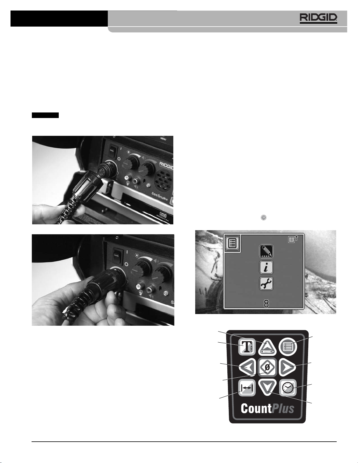
2. Unwrap the SeeSnake System Cable from its holder
on the reel frame and plug its connector into the
matching connector on the CCU. To join the connectors, align the guide pin to the guide socket, push
the connector straight in and tighten the outer locking
sleeve. A molded ridge along the top of the strain-relief molding will help keep the top side of the plug oriented upward.
Twist only the locking sleeve! Never bend
or twist the connector. Bending or twisting the connector
will lead to premature failure.
Figure 23 – Aligning System Cable Plug
Figure 24 – Connecting System Plug To CCU
Mechanical Checks
1. Adjust the reel’s brake so the drum turns easily when
you pull cable from the reel but stops turning when
you stop pulling the cable. If the drum turns too easily, excess cable could exit the reel.
2. Grasp the spring assembly in one hand and the
camera head in the other. Check that the camera
head is seated firmly but is not tightened to the point
the end of the spring rides up and over the threads.
3. Check to see that the connector at the end of the
pushrod is fully seated into the connector attached to
the hub (inside the reel). Likewise, check that the
system cable is completely plugged into the hub.
Electrical Checks
The SeeSnake camera and the Count
Plus
are powered
up when the connected camera control unit is turned on.
The system should produce a crisp picture that is free of
noise and lines. It may need to warm up before it will produce the optimum picture.
Look to see that an even amount of light is coming from
the LEDs on the camera head. To test the slip ring, place
the camera in the reel and spin the drum while watching
your monitor. If you do not get a stable picture, call
RIDGID Technical Service at 800-519-3456.
Count
Plus
Settings
The Count
Plus
is a distance-counter which can track the
total length of pushrod that has been run out of the
drum or measure distance from some local zero-point selected during the inspection (such as a pipe head or
joint). The Count
Plus
can also display overlays of text
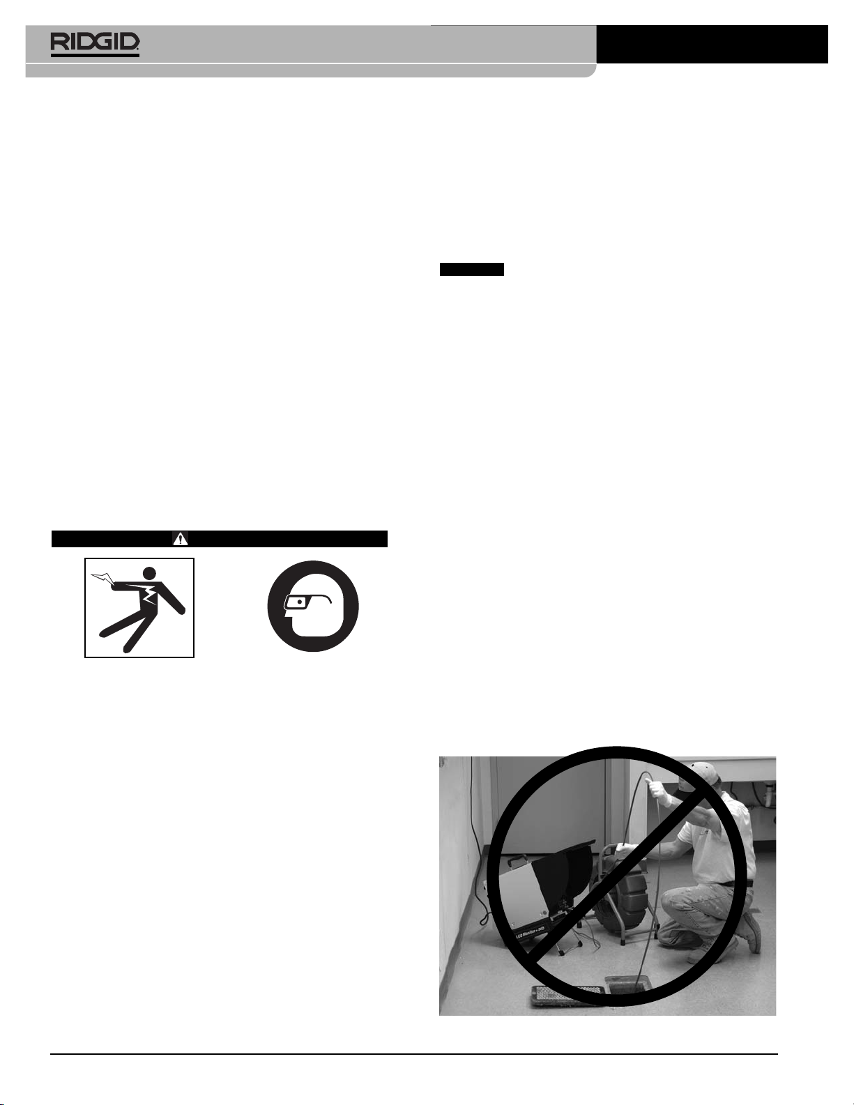
messages such as labels of pipe line features. Press on
the Count
Plus
Menu Key , to bring up the Main Menu
screen with three icons on it.
Figure 25 – Count
Plus
Main Menu
Figure 26 – Count
Plus
Keypad
NOTICE
Menu Key
Right
Arrow Key
Time Key
Down
Arrow Key
Up/Edit
Arrow Key
Text Key
Left Arrow
Key
Zero/Select
Key
Distance
Key
Find Quality Products Online at: [email protected]
www.GlobalTestSupply.com
Page 14
Ridge Tool Company
12
The Count
Plus
interface allows you to set up and modify a number of important parameters for use with your
SeeSnake System. These include:
• System Time
• System Date
• Reel and Cable
• Units of Measure
You will also need to be familiar with:
• Setting Up Text Slides
• Creating a New Slide
• Editing an Existing Slide
• Choosing a Slide for Display
• Turning Slide Display On or Off
• Deleting a Slide
These are described in the separate Count
Plus
manual.
Please read the complete Count
Plus
manual and ensure
you are familiar with the operation of the Count
Plus
when doing an inspection with a SeeSnake System.
Operating Instructions
WARNING
Always wear eye protection to protect your eyes
against dirt and other foreign objects.
When inspecting drains that might contain hazardous chemicals or bacteria, wear appropriate
protective equipment, such as latex gloves, goggles,
face shields or respirators to prevent burns and
infections.
Do not operate this equipment if operator or machine is standing in water. Operating machine while
in water increases the risk of electrical shock.
Rubber soled, non-slip shoes can help prevent slipping and electric shock, especially on wet surfaces.
Follow operating instructions to reduce the risk of
injury from electrical shock and other causes.
1. Make sure all equipment is properly set up.
2. Place the camera head into the reel’s guide hoop and
turn the CCU’s power on. You should see the words
“Count
Plus
” and a version number on the monitor
screen. Leave the camera head in the guide hoop
until this start-up screen disappears (approx. 5 sec.).
If you do not see an image on the monitor, check to
make sure its power is turned ON and it is set to
the correct source (see CCU manual).
In very cold weather, the camera may take a few
moments to warm up when first turned ON. This is
especially true if the camera has been stored in a cold
environment for several hours. When you turn ON the
system, you may notice a “noisy” picture for a few moments. This is natural while the camera warms up.
The camera head can get HOT! When finished with your inspection or if taking a prolonged
break in the middle of the inspection, turn OFF the
system.
If the camera sits in a pipe, or any enclosed environment, heat will build up. This may lead to the camera head
overheating which will cause fuzzy lines to appear on
the monitor. In the event this happens, turn off the system,
remove the camera from the pipe (or enclosed environment) and let the camera head cool for 10 to 15 minutes.
Running water into the line will also help cool the camera
head. Always use the minimum illumination required to
maximize picture quality and to avoid excessive heat
build-up.
Ask customers what is in the line or what the line is
used for prior to putting the camera into the line.
Avoid lines containing harsh solvents, chemicals, an electrical charge or excessive heat.
Performing A Pipe Inspection
Inspecting a pipe is done by pushing the camera into
the pipeline gradually while observing the monitor.
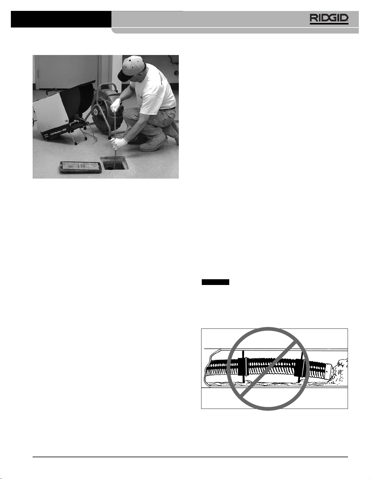
1. When pushing, the end of your stroke should be as
close to the entry as possible. Standing too far back
(with an excess of cable between your hands and the
entry) may cause the cable to fold on itself outside the
entry and damage the cable
(Figure 27)
.
Figure 27 – Improper Cable Push
SeeSnake®Standard and Mini Pipe Inspection Systems
NOTICE
Find Quality Products Online at: [email protected]
www.GlobalTestSupply.com
Page 15
Ridge Tool Company
13
Figure 28 – Proper Cable Push
2. Folding the pushrod on the sharp edge of an entry
can cause it to snap. Caution must be used to avoid
bending the pushrod on sharp corners. This can
cause pushrod failure. If the camera just does not
seem to want to go any farther, do not force the
camera. Try another entry-point if one is available. Or,
try running water down the line.
NOTE! Hands should be close to the line opening.
DO NOT catch the cable on the edge of an
entry and continue to push.
The camera can almost always be pushed farther
when grip-style rubber gloves are worn. It is much eas-
ier to get a grip on dirty pushrod, and the gloves also keep
sludge off the hands.
Run water down the pipe undergoing inspection if
possible. This will keep the system much cleaner and
allow you to push noticeably farther with less friction.
This will also help you locate the bottom of the pipe.
This can be accomplished by feeding a hose with a small
amount of flow into the entry or occasionally flushing a toilet that drains to the pipe. If the water is preventing you
from seeing an area of importance, temporarily turn it
off.
When inspecting a pipe, it is usually necessary to give
a little extra push in the bends. Back the camera head
approximately 8” from the bend, if necessary and give it a
quick push, “popping” the camera through a turn, using the
least amount of force required. Be as gentle as possible.
Do not hammer or snap the camera head through corners.
The best way to inspect a section of pipe in some situations is to push the camera through quickly and draw
the camera back home slowly and evenly. It is easier to
control the camera when pulling than when pushing.
Make sure the sapphire window is clean prior to
entry. Some users claim that a slight film of detergent on
the lens minimizes the possibility of grease sticking to the
port. If necessary, take advantage of any standing water
in the pipe to wash the front of the camera by jiggling it in
the water.
Take advantage of the lighting to keep track of where
the camera is headed. If the particular pipe you are in-
specting is easier to evaluate with other than the maximum
lighting, periodically maximize the lighting (using the dimmer knob) to get a look at what lies ahead. Be aware of
any obstructions, such as a crushed section of pipe or excessive hard build-up that may prevent retrieval of the
camera.
When you place the camera head into the pipe, remember, as the materials of pipe vary, it will be necessary to adjust the lighting settings to maximize
picture quality. For example, white PVC pipe requires
less lighting than black ABS. As experience is gained with
the system, operators will learn that slight adjustments in
these settings can highlight problems within a pipe.
Always use the minimum illumination required to prevent excessive heat build-up and to maximize picture
quality.
Adjustment of the contrast and brightness settings on
the monitor, as well as the light dimmer after the
camera is within the pipe, can greatly increase picture
quality. This is particularly important when your cus-
tomer is supervising and when making recordings.
Do not clear obstructions with the camera
head. This may cause premature failure to your camera head. The SeeSnake is a diagnostic tool that
identifies problems. Other tools should be used to
make effective repairs. It should never be used to
clear obstructions.
See Figure 29.
Figure 29 – Improper Use of Camera to Clear
Obstruction
SeeSnake®Standard and Mini Pipe Inspection Systems
NOTICE
Find Quality Products Online at: [email protected]
www.GlobalTestSupply.com
Page 16
Ridge Tool Company
14
If AC power for the monitor is not available, you can
operate the system using a voltage converter that
plugs into your vehicle's cigarette lighter.
The system can travel through multiple 45 and 90 degree bends and wyes. Do not, however, try to force it
through a P-trap or Tee if there is a large amount of
resistance.
If you are planning to use locating equipment with
your camera, use only SeeSnake
®
transmitters. The
SeeSnake®built-in Sonde is specifically designed for
years of service and does not interfere with the camera's
ability to travel bends. Taping a non-SeeSnake®transmitter to the pushrod will interfere with the camera's ability to negotiate bends.
Do not attempt to remove or store pushrod on the
reel solely by turning the reel itself. Release the brake
enough so that you can manually push or pull cable from
the reel and wind or unwind it. If for some unusual reason
the drum should not turn, do not try to pull the pushrod out
of the reel. This will force the cable to collapse down
around the hub causing unnecessary stress on the cable.
Be careful in Tee-entries not to fold the camera back on
itself. This could cause the camera to stick.
Using the Count
Plus
With the SeeSnake connected and powered ON, use
the Distance Key and the Time Key to set the display with the information you prefer.
a) The Time Key will toggle the display between Date,
Date and Time, Time or No Date and Time displayed. Press the key once for each step through the
choices.
b) The Distance Key will toggle the display of distance
on the screen between ON and OFF.
c) The distance counter will show the distance in the
units set in the Tools /Units menu.
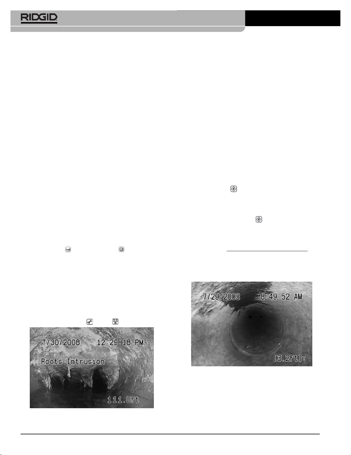
Figure 30 – Display Screen With Slide Text, Time and
Distance Shown (Distance Measured From
System Zero-Point)
System Zero-Point and Local Zero Point
The counter, as shown in
Figure 30
, starts from zero
when the system is powered ON. This is called the system zero-point. You can change the physical point the
system measures from by powering the system OFF,
running the cable in or out to the desired zero point
and powering ON from that point. The counter resets to
zero when the system is powered ON again.
Resetting the System Zero-Point: You can also reset
this system zero point at anytime with a long press (> 3
seconds) on the Zero Key. It is good practice to do this,
for example, at the entrance to a pipe.
Setting a Local Zero-Point: In addition, while it is operating, the Count
Plus
can be made to also start counting from any custom “local zero-point” you select with a
second counter.
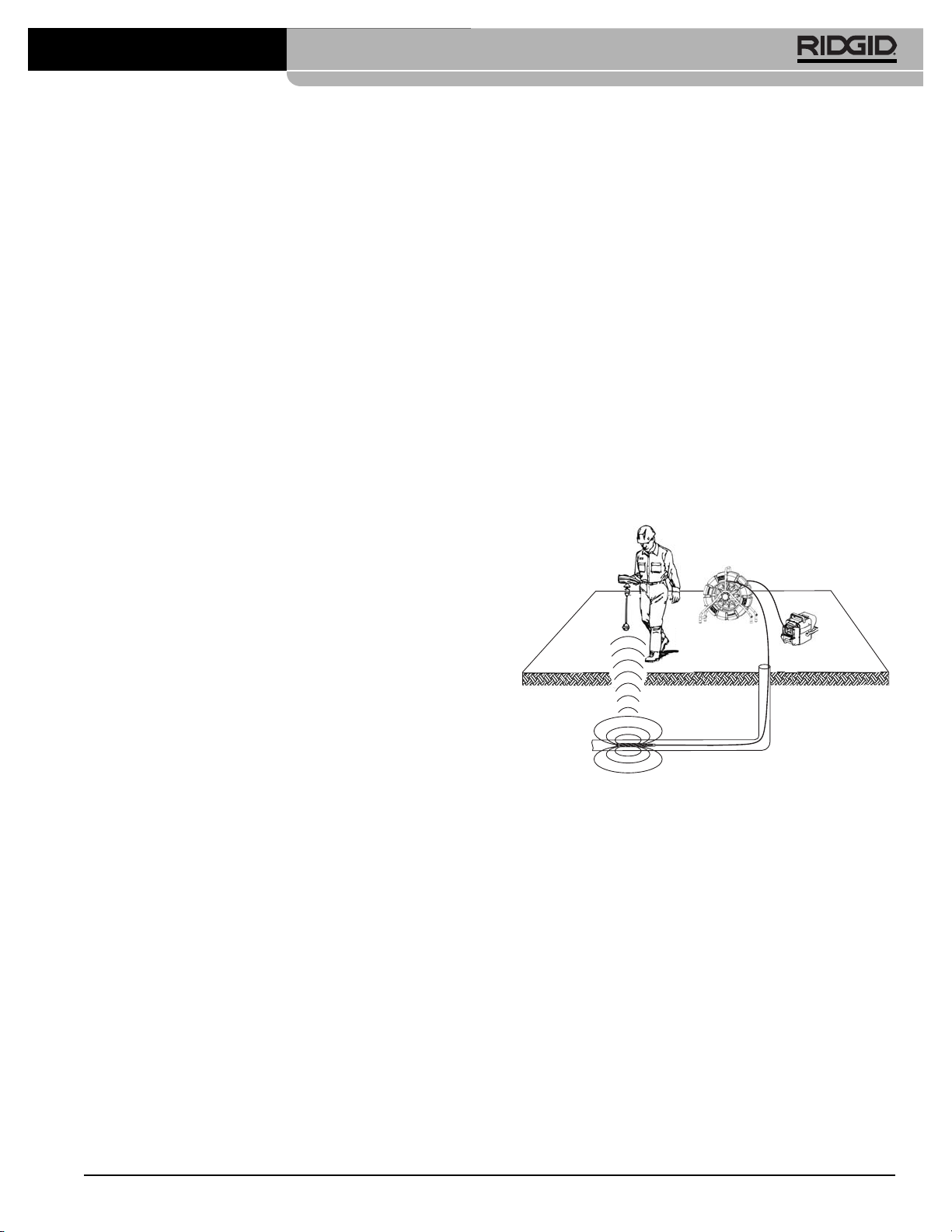
1. To begin a separate distance count from a selected
point, such as a junction within a pipeline, press the
Zero/Select Key briefly. The distance display will reset to [0.0]. The square brackets indicate that you are
measuring from a local zero-point rather than the
system zero-point.
a) Pressing the Zero Key will now toggle the dis-
play between the default count and the new [0.0]
point.
b) Once you start measuring cable feed from a local
zero-point, do not press the Zero Key again until
you have completed the measurement you are
working on, as pressing it will reset the custom
zero-point again and lose the measurement you
have been taking.
Figure 31 – Measuring From A Local Zero-Point
c) As a precaution you may want to write down the
system measurement’s initial value just before
setting a new zero point. (This will enable you to
compute the distance manually using the system count, if you reset the local zero-point accidentally).
SeeSnake®Standard and Mini Pipe Inspection Systems
Find Quality Products Online at: [email protected]
www.GlobalTestSupply.com
Page 17
Ridge Tool Company
15
2. The SeeSnake will continue to count the distance the
cable is extended and display the current total (if
the display of distance is toggled on) from the system
zero-point or from the current local zero-point, if one
has been set.
Getting Consistent Measurements
Make sure all the cable is in the reel before powering up
the system. Wait for the initialization screen to disappear
before moving the camera head from the guide hoop.
This takes about 10 seconds.
Avoid moving the reel once you have started your measurements.
Make sure the cable length, cable diameter and drumsize settings are correct for your system.
If the system is shut down or loses power for more
than 10-20 seconds the SeeSnake may re-zero its system zero point of reference, and any local zero-point
count will be lost.
When spooling the cable into the drum, maintain a uniform friction or drag on the cable to ensure it does not
bunch up in the drum.
Accuracy: In general use, the SeeSnake reported distance will be accurate to within 3 feet (1 meter). This accuracy depends on cable tension, correct reel settings
and other factors.
For greatest accuracy:
1. Make sure the camera head is in or nearly in the
guide hoop when powering up. This ensures the distance computing is done from a full reel.
2. For measurements starting from somewhere other
than the reel, such as the head of a drain line, reset
the “system zero” point with a long press (> 3 seconds) on the Zero Key, or use the “local zero” option
(by pressing the Zero/Select key) briefly, rather than
powering up with a significant length of cable already run out.
A “dead battery” icon will appear at start-up if the
CountPlus’ battery has died.
A “+” sign will appear after the distance measurement
on-screen if the measured distance exceeds the selected cable length chosen in set-up.
Locating the Sonde
The SeeSnake has a built-in Sonde which when turned on
transmits a locatable 512 Hz signal.
Using a SeeSnake camera control unit (CCU), you will
also be able to activate the Sonde, located just behind the
camera head, from the CCU. Controlling the Sonde from
the CCU is described in the Operator’s Manual for the
CCU and depends on the model being used.
When the Sonde is turned ON, a locator such as the
RIDGID SR-20, SR-60, Scout or NaviTrack II set to 512
Hz will be able to detect it. The most workable approach
to tracking the Sonde is to run the pushrod into the pipe
about five or ten feet (1.5 to 3 meters) and use the locator to find the Sonde’s position. If desired, you can then extend the pushrod a similar distance further down-pipe
and locate the Sonde again starting from the previous located position.
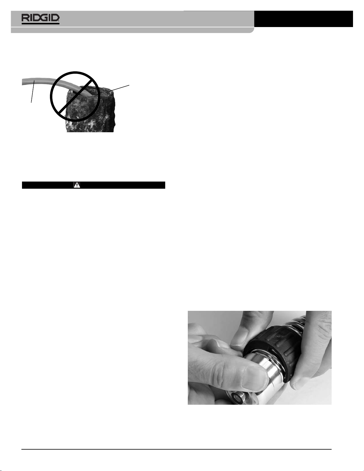
To locate the Sonde, turn the locator ON and set it to 512
Hz Sonde mode. Scan in the direction of the Sonde’s
probable location until the locator detects the Sonde.
Once you have detected the Sonde, use the locator indications to zero in on its location precisely. For detailed instructions on Sonde locating, consult the Operator’s
Manual for the locator model you are using.
Figure 32 – Locating The Sonde
Some faint background striations may appear on
the CCU monitor when the built-in 512 Hz transmitter is turned ON. This is normal.
Retrieving the Camera
Once the inspection has been completed, pull the pushrod
back with slow, steady force. Continue running water
down the line if possible to help clean the pushrod. A towel
can be used to wipe off the pushrod as it is withdrawn.
Pay attention to the force required to withdraw the pushrod. The pushrod and camera may get hung up while
being retrieved and may need to be manipulated as done
during insertion. Do not force the pushrod or exert excessive force. This could damage the camera or pushrod.
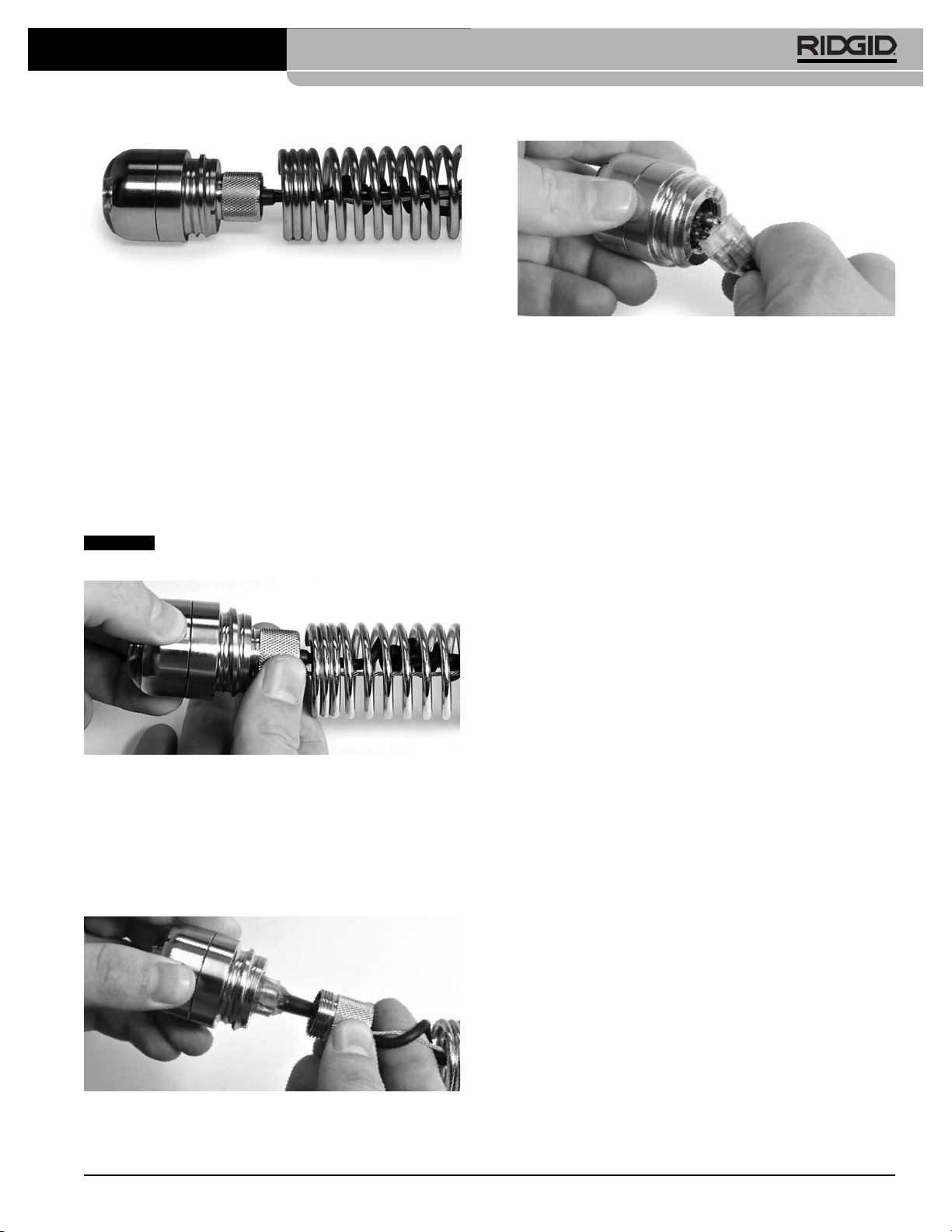
When pulling the pushrod, keep clear of any sharp edges
and do not pull at sharp angles to the inlet to prevent damage to the pushrod jacket.
SeeSnake®Standard and Mini Pipe Inspection Systems
Find Quality Products Online at: [email protected]
www.GlobalTestSupply.com
Page 18
Ridge Tool Company
16
As the pushrod is withdrawn from the inlet, feed it back
into the drum.
Figure 33 – Avoid Pulling At Sharp Angles
Maintenance Instructions
Cleaning Instructions
WARNING
Make sure that the system cable is disconnected
from the CCU prior to cleaning to reduce the risk of
electrical shock.
NOTE! Never use solvents to clean any part of the
system.
Use a soft nylon brush, mild detergent and rags and
sponges to clean camera, spring assembly and cables.
When cleaning the camera, do not use scraping tools as
they may permanently scratch these areas. NEVER USE
SOLVENTS to clean any part of the system, as they can
cause cracking of the LED ring, which could affect waterproofing.
Stretch the spring and stir in warm water to flush grime
from the spring assembly.
To thoroughly clear the reel and drum, stand the reel
upright and fill the bottom of the drum with lukewarm
water and a mild detergent. Spin the drum to loosen the
grime. Remove the water, pull out the cable and run a rag
over the cable as you feed it back into the drum.
Never fill the drum while the unit is tipped on its
back. Water can enter the hub and damage the slip
rings.
Camera Maintenance
Camera Head
The camera head requires little maintenance, other
than keeping the LED ring and sapphire window clean.
Use a soft nylon brush, mild detergent and rags.
Scratches on the LED ring will have a minimal effect on
the performance of the lighting. DO NOT sand the LED
ring to remove scratches, as it is part of the watertight
housing.
Spring Assembly
The spring assembly is the area where foreign matter is
most likely to accumulate. Within the spring is the splice
between the pushrod and a connector. Should sharp objects or harsh chemicals be allowed to remain in this area
for long periods, they may wear on these components.
Stretch the spring end-to-end as far as the internal
safety cables allow to check this area.
Removing Camera Head
Before removing the camera head for the first time,
be sure to read the following instructions. Bending or
twisting the camera head connectors will lead to premature failure and is not covered by warranty. Do not
bend or twist connectors! Twist only the locking sleeves.
If you need additional assistance, please call Ridge
Tool Technical Service (800-519-3456) before proceeding.
The system has been designed so that the camera
head can be removed for troubleshooting. To remove the
camera head, the following procedure must be followed:
1. Pay out enough cable to place the camera and spring
assembly on a work bench or other convenient work
area. Set the brake to prevent the reel from spinning.
2. Locate the spring wrench that was provided with the
system and engage the cut end of the spring (directly behind the camera head) with the wrench. The
hand that is holding the wrench should remain still
while turning the camera off the spring with the other
hand.
Figure 34 – Turning Camera Head Off The Spring With
Spring Wrench
The camera should now be hanging by its locking sleeve
and safety cable.
SeeSnake®Standard and Mini Pipe Inspection Systems
Pushrod
Drain Inlet
Find Quality Products Online at: [email protected]
www.GlobalTestSupply.com
Page 19
Ridge Tool Company
17
Figure 35 – Camera Head Separated From Spring
Assembly
3. Grasp the ribbed portion of the locking sleeve with
one hand and the camera with the other. Rotate the
ribbed portion of the sleeve (counter-clockwise when
camera is viewed from the rear) to unscrew it from the
camera housing threads while holding the camera
head still with the other hand. If the locking sleeve is
difficult to turn, get it started with a pair of pliers
whose jaws have been wrapped in electrical tape
to prevent scarring the locking sleeve. Do not crush or
deform the locking sleeve by exerting excessive
pressure.
Twist only the locking sleeve, not the
camera.
Figure 36 – Removing Camera Head From Locking
Sleeve
Be sure not to let the safety cables twist more than
one rotation. The design minimizes the chance of this
happening; however, it may be necessary to hold the
safety cables when you turn the locking sleeve, to ensure
you aren't turning the safety cables.
Figure 37 – Separating Locking Sleeve From Camera
Head
Figure 38 – Unplugging The Camera Head
4. When the locking sleeve is completely unscrewed
from the camera housing female threads, the connector should automatically disengage from the camera. If this does not occur, grab the locking sleeve and
connector in one hand, the camera head in the other,
and pull them straight out of the back of the camera.
DO NOT twist the connectors! Be sure to separate
connectors by pulling straight.
Re-Installing Camera Head
Lay out enough cable to lay the spring assembly on a
convenient work area and set the brake.
1. Plug the connector and locking sleeve into the camera head, making sure that the guide pins/sockets are
aligned. Be sure to fully seat the connectors without
any twisting.
2. Once the connectors are fully seated, grasp the camera head with one hand and turn the ribbed portion of
the locking sleeve to screw it into the back of the camera. Be sure not to let the safety cables twist more
than one rotation. The design minimizes the chance
of this happening; however, it may be necessary to
hold the safety cables in such a manner that when
you turn the locking sleeve, you aren't turning the
safety cables.
3. Once the locking sleeve is tight into the back of the
camera and the safety cables are parallel to each
other, install the spring assembly onto the threads on
the camera housing exterior. To do this, turn the
camera head one rotation in the counter clockwise direction until the threads properly align, and then rotate
the camera head clockwise onto the spring assembly.
This method will help keep the safety cables from
twisting inside the spring. Be sure to use only your
hands (i.e. no tools) when screwing the camera onto
the spring.
The camera head will be properly mounted when the end
of the spring is snug between the camera and the thread
(not so far that it begins to raise off the threads) and you
cannot manually unscrew the camera.
SeeSnake®Standard and Mini Pipe Inspection Systems
NOTICE
Find Quality Products Online at: [email protected]
www.GlobalTestSupply.com
Page 20
Ridge Tool Company
18
Push Cable, Reel/Frame
The pushrod and reel/frame require almost no maintenance. (Of course, a clean system will last longer and be
more impressive to your customers). It is important,
however, to keep the pushrod clean to spot any excessive cuts or abrasions, while making it much easier
to grasp and push.
Whenever you are retrieving pushrod into the reel, cut
down on cable grime by running the cable through a rag
in the last hand that touches the cable as it enters the reel.
1. Visually inspect the cable for cuts and abrasions as
you feed it back into the drum. If the outer jacket is cut
or abraded through, the cable may need to be replaced or repaired (re-terminated).
2. In most cases it’s best to service a damaged cable as
soon as possible, but there may be some exceptions (when a cable is old and worn or when a re-termination repair would remove too much cable, for
example). Call the Ridge Tool Technical Services
Department to discuss your situation and develop
an appropriate plan of action.
A damaged cable may allow water to migrate along
the inside. When the cable is re-terminated, the entire
wet portion of cable must be cut off to allow for a proper
termination onto a dry section of cable. Although the system may remain operable for a long period of time with
a damaged (wet) cable, continued use may result in
significantly more cable being cut off when a repair is finally needed.
Changing the Count
Plus
Battery
The SeeSnake Count
Plus
has its own 3-volt CR2450
battery, which is exposed in a clip holder when the
Count
Plus
is opened by removing the four screws holding
the container to the cover and lowering the container. This
battery should have a working life of several years.
To change the battery:
1. Disconnect the SeeSnake System Cable from the
CCU.
2. Remove four screws which attach the body of the
Count
Plus
container to the top of the Count
Plus
.
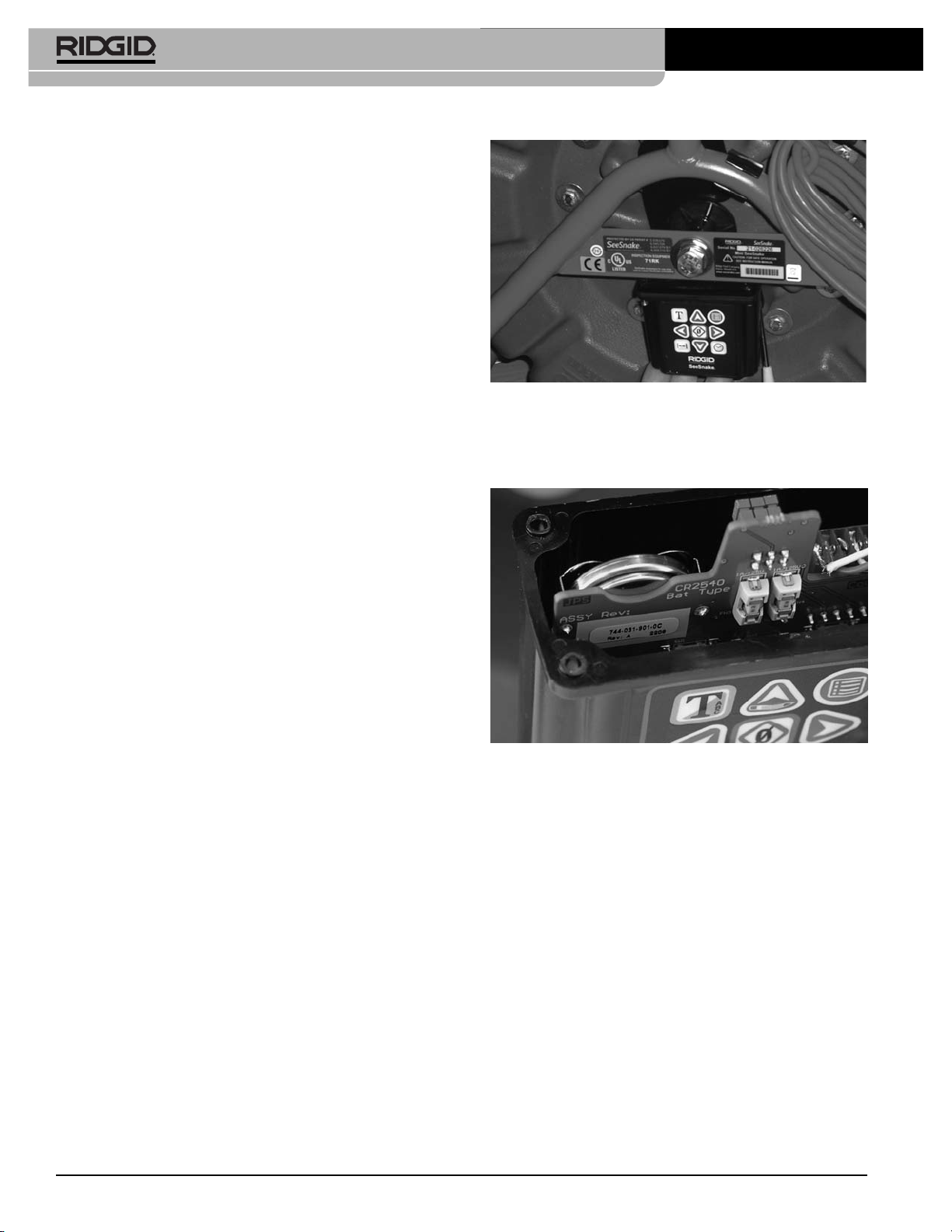
Figure 39 – Removing The Count
Plus
3. As you lower the Count
Plus
container, you will see a
silver battery-clip containing a disk-shaped battery
on the left-side back of the circuit board.
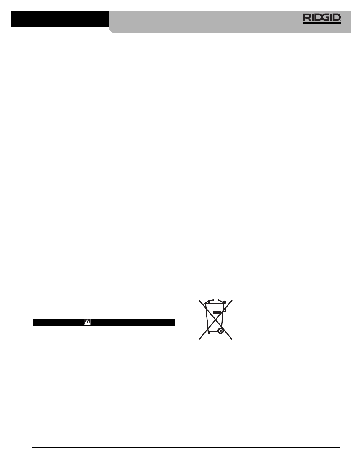
Figure 40 – Count
Plus
Battery
4. Slip the battery out of the clip taking care to note the
polarity and replace with an identical 3V CR2450
with the plus (+) side facing the same way the original
one was.
5. Carefully realign the container with the top, making
sure the gasket is correctly aligned and re-seat the
four screws. Tighten the screws until each one is
hand-tight. Be sure you have not pinched any wires or
the gasket in installing the container.
6. Test the Count
Plus
by plugging the reel into the camera control unit. When the camera view appears it
should have the date/time and distance display overlaid on the camera image.
Camera Control Unit
The CCU requires a little more care. The same is true for
any monitor in the field. Unlike the rest of the system, the
CCU’s are not waterproof. Clean them with a damp cloth
SeeSnake®Standard and Mini Pipe Inspection Systems
Find Quality Products Online at: [email protected]
www.GlobalTestSupply.com
Page 21
Ridge Tool Company
19
and ensure foreign matter does not get into any cooling
vents. Always avoid dropping or shocking these components. See your CCU manual for complete instructions.
Locating Faulty Components
If you have a known working camera head, it can be
used as a test device to isolate a faulty component in the
system. It can be plugged directly into the CCU system
connector to test the CCU. It can be plugged into the hub
end of the System Cable or into the push-rod connector
inside the drum in order to test each link in the series.
Try to isolate the fault to one of the major components:
• camera head
• reel/frame
• systems cable
• CCU
Contact Ridge Tool Technical Services Department at
800-519-3456 for assistance. We will establish a plan of
action to get your system back on line.
For additional troubleshooting suggestions, please
see
the Troubleshooting Chart on page 20
.
The system is designed to let you troubleshoot faulty
components at the job site. In the unlikely event that you
encounter problems with your system, you may still be
able to finish the job. If you isolate the problem to the hub,
you can disconnect the pushrod at the dry-end, remove all
the cable from the drum and pay out all the cable in a convenient location. Disconnect the system cable at the
back side of the hub and connect the dry-end pushrod
connector to the system cable connector. Although this
may be inconvenient, it will allow you to finish the job.
Accessories
WARNING
The following accessories have been designed to
function with the SeeSnake System. Other accessories suitable for use with other equipment may
become hazardous when used with the SeeSnake
System. To reduce the risk of serious injury, only
use accessories specifically designed and recommended for use with the SeeSnake System, such as
those listed below.
Catalog # Description
Various RIDGID®SeekTech®or NaviTrack
®
Locators
Various RIDGID SeekTech®or NaviTrack
®
Transmitters
Various RIDGID SeeSnake®Camera Control Units
Various Pipe Guides
Transport and Storage
Do not expose to heavy shocks or impacts during transport. Store in environments within temperature range of
-4°F to 158°F (-20°C to. 70°C).
Disposal
Parts of the SeeSnake System contain valuable materials and can be recycled. There are companies that specialize in recycling that may be found locally. Dispose of
the components in compliance with all applicable regulations. Contact your local waste management authority
for more information.
Do not dispose of electrical equipment
with household waste!
According to the European Guideline
2002/96/EC for Waste Electrical and
Electronic Equipment and its implemen-
tation into national legislation, electrical
equipment that is no longer usable must be collected
separately and disposed of in an environmentally correct
manner.
SeeSnake®Standard and Mini Pipe Inspection Systems
Find Quality Products Online at: [email protected]
www.GlobalTestSupply.com
Page 22
Ridge Tool Company
20
SeeSnake®Standard and Mini Pipe Inspection Systems
Camera video image not
seen.
Count accuracy seems
unreliable.
Low Battery warning
appears.
The symbol “+” appears
after the on-screen distance measurement.
No power to SeeSnake CCU connector.
Connections faulty.
Video Source incorrect.
Settings incorrect for reel or cable being used.
Counting from a zero point other than the one intended.
Battery dead or near-dead.
Physical cable measurement has exceeded the
cable parameter in settings.
Check power is correctly plugged in.
Check switch on SeeSnake CCU.
Check alignment and pins of connection to CCU
or DVR unit from SeeSnake.
Check orientation, seating, and pin condition in the
SeeSnake connection.
Check CCU Video Source setting. See CCU
manual.
Verify the settings are correct for the SeeSnake
cable length, cable diameter and reel type you are
using.
Confirm you are measuring from the intended zeropoint.
Replace 3-volt battery in the Count
Plus
(CR2450).
Verify the actual length of your installed cable; re-set
the reel and cable settings for the correct reel type
and actual cable length and diameter as described
on
page 14
or in your Count
Plus
manual.
PROBLEM PROBABLE FAULT LOCATION SOLUTION
Chart 1 Troubleshooting
Find Quality Products Online at: [email protected]
www.GlobalTestSupply.com
 Loading...