

Page 1

WARNING!
Operator’s Manual
Read this manual carefully before using this tool.
Failure to understand and
follow the contents of this
manual may result in electrical shock, fire, and/or serious injury.
Find Quality Products Online at: [email protected]
www.GlobalTestSupply.com
Page 2

Table of Contents
Introduction
Regulatory Statements ...............................................................................................................................................3
Safety Symbols ...........................................................................................................................................................3
General Safety Rules
Work Area Safety ........................................................................................................................................................ 4
Electrical Safety .......................................................................................................................................................... 4
Personal Safety ..........................................................................................................................................................4
Equipment Use and Care ...........................................................................................................................................5
Pre-Operation Inspection
Specific Safety Information
SeeSnake Compact2 Safety ......................................................................................................................................6
Product Overview
Description
Specifications
Standard Equipment ................................................................................................................................................... 8
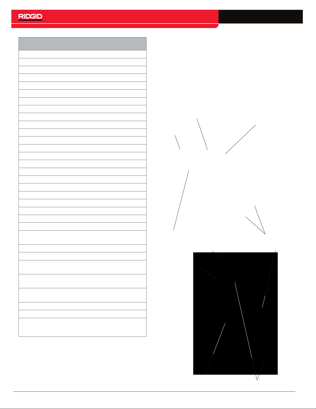
System Components .................................................................................................................................................. 8
Operating Instructions
Placement ................................................................................................................................................................ 10
Routing the Camera .................................................................................................................................................10
Connecting to a SeeSnake Monitor .......................................................................................................................... 11
Inspection Overview ................................................................................................................................................. 12
Best Practices ........................................................................................................................................................... 13
Pipe Guides .............................................................................................................................................................. 14
Locating the Sonde .................................................................................................................................................. 15
Line Tracing the Push Cable ..................................................................................................................................... 16
Retrieving the Camera .............................................................................................................................................. 16
Individual Components
Self-Leveling Camera ............................................................................................................................................... 17
System Cable Assembly ........................................................................................................................................... 17
Docking System ........................................................................................................................................................ 18
Maintenance and Support
Maintaining Components .......................................................................................................................................... 20
Cleaning ...................................................................................................................................................................21
Accessories .............................................................................................................................................................. 22
Transport and Storage .............................................................................................................................................. 22
Service and Repair ................................................................................................................................................... 22
Disposal ....................................................................................................................................................................22
Troubleshooting ........................................................................................................................................................23
Appendices
Appendix A: Docking Fin Removal ............................................................................................................................24
Appendix B: Camera Fault Isolation .........................................................................................................................24
Appendix C: Camera Removal .................................................................................................................................25
Appendix D: Camera Installation ..............................................................................................................................26
.................................................................................................................................................................7
.............................................................................................................................................................8
2 – English
Find Quality Products Online at: [email protected]
www.GlobalTestSupply.com
Page 3
Introduction
The warnings, cautions, and instructions discussed in this manual cannot cover all possi-
ble conditions and situations that may occur. It
must be understood by the operator that common sense and caution are factors which cannot
be built into this product, but must be supplied
by the operator.
Regulatory Statements
The EC Declaration of Conformity (890-011-
320.10) will accompany this manual as a separate booklet when required.
This device complies with Part 15 of FCC rules.
Operation is subject to the following two conditions: (1) This device may not cause harmful interference, and (2) this device must accept any
interference received, including interference that
may cause undesired operation.
Safety Symbols
In this manual and on the product, safety symbols and
signal words are used to communicate important safety
information. This section is provided to improve understanding of these signal words and symbols.
This is the safety alert symbol. It is used to alert
you to potential injury hazards. Obey all safety
messages that follow this symbol to avoid possible injury or death.
DANGER
DANGER indicates a hazardous situation which, if not
avoided, will result in death or serious injury.
WARNING
WARNING indicates a hazardous situation which, if not
avoided, could result in death or serious injury.
CAUTION
CAUTION indicates a hazardous situation which, if not
avoided, could result in minor or moderate injury.
NOTICE
NOTICE indicates information that relates
to the protection of property.
This symbol means read the operator’s manual
carefully before using the equipment. The manual contains important information on the safe
and proper operation of the equipment.
This symbol means always wear safety glasses
with side shields or goggles when handling or
using this equipment to reduce the risk of eye injury.
This symbol indicates the risk of electrical shock.
English – 3
Find Quality Products Online at: [email protected]
www.GlobalTestSupply.com
Page 4

General Safety Rules
WARNING
Read all safety warnings and instructions. Failure to
follow the warnings and instructions may result in
electrical shock, fire, and/or serious injury.
SAVE THESE INSTRUCTIONS!
Work Area Safety
• Keep your work area clean and well lit. Cluttered or
dark areas invite accidents.
• Do not operate equipment in explosive atmo-
spheres, such as in the presence of flammable liquids, gases, or dust. Equipment can create sparks
which may ignite the dust or fumes.
• Keep children and bystanders away while operat-
ing equipment. Distractions can cause you to lose
control.
• Avoid traffic. Pay attention to moving vehicles when
using on or near roadways. Wear high-visibility clothing or reflector vests.
Electrical Safety
• Avoid body contact with earthed or grounded surfaces such as pipes, radiators, ranges, and refrigerators. There is an increased risk of electrical shock
if your body is earthed or grounded.
Personal Safety
• Stay alert, watch what you are doing, and use common sense when operating equipment. Do not use
equipment while you are tired or under the influence of
drugs, alcohol, or medication. A moment of inattention
while operating equipment may result in serious injury.
• Dress properly. Do not wear loose clothing or jewelry.
Loose clothes, jewelry, and long hair can be caught in
moving parts.
• Practice good hygiene. Use hot, soapy water to wash
hands and other body parts exposed to drain contents
after handling or using drain inspection equipment. To
prevent contamination from toxic or infectious material, do not eat or smoke while operating or handling
drain inspection equipment.
• Always use appropriate personal protective equip-
ment when handling and using equipment in
drains. Drains may contain chemicals, bacteria, and
other substances that may be toxic, infectious, and
cause burns or other issues. Appropriate personal protective equipment always includes safety glasses and
may include a dust mask, hard hat, hearing protection,
drain cleaning gloves or mitts, latex or rubber gloves,
face shields, goggles, protective clothing, respirators,
and steel toed, non-skid footwear.
• If using drain cleaning equipment and drain in-
spection equipment at the same time, wear RIDGID
drain cleaning gloves. Never grasp the rotating drain
cleaning cable with anything else, including other
gloves or a rag which can become wrapped around
the cable and cause hand injuries. Only wear latex
or rubber gloves underneath RIDGID drain cleaner
gloves. Do not use damaged drain cleaning gloves.
• Do not expose equipment to rain or wet condi-
tions. Water entering equipment will increase the risk
of electrical shock.
• Keep all electrical connections dry and off the
ground. Touching equipment or plugs with wet hands
can increase the risk of electrical shock.
• Do not abuse the cord. Never use the cord for car-
rying, pulling, or unplugging the power tool. Keep cord
away from heat, oil, sharp edges, and moving parts.
Damaged or entangled cords increase the risk of electrical shock.
• If operating equipment that is powered by an AC
adapter in a damp location is unavoidable, use a
ground fault circuit interrupter (GFCI) protected
supply. Use of a GFCI with an AC adapter reduces
the risk of electrical shock.
4 – English
Find Quality Products Online at: [email protected]
www.GlobalTestSupply.com
Page 5

Equipment Use and Care
• Do not force equipment. Use the correct equipment
for your application. The correct equipment does the
job better and more safely.
• Do not use equipment if the power switch does not
turn it on and off. Any equipment that cannot be controlled with the power switch is dangerous and must
be repaired.
• Disconnect the plug from the power source and/or
the battery pack from the equipment before making adjustments, changing accessories, or storing.
Preventive safety measures reduce the risk of injury.
Pre-Operation Inspection
WARNING
To reduce the risk of serious injury from electrical
shock or other causes, and to prevent damage to
your equipment, inspect all equipment and correct
any problems before each use.
• Store idle equipment out of the reach of children
and do not allow persons unfamiliar with the equipment or these instructions to operate the equipment. Equipment can be dangerous in the hands of
untrained users.
• Maintain equipment. Check for misalignment or bind-
ing of moving parts, missing parts, breakage of parts,
and any other condition that may affect the equipment’s operation. If damaged, have the equipment
repaired before use. Many accidents are caused by
poorly maintained equipment.
• Do not overreach. Keep proper footing and balance
at all times. This enables better control of the equipment in unexpected situations.
• Use the equipment and accessories in accordance
with these instructions; taking into account the
working conditions and the work to be performed.
Use of the equipment for operations different from
those intended can result in hazardous situations.
• Use only accessories that are recommended by
the manufacturer for your equipment. Accessories
that may be suitable for one piece of equipment may
become hazardous when used with other equipment.
• Keep handles dry, clean, and free from oil and
grease. Clean handles give better control of the equipment.
To inspect all equipment, follow these steps:
1. Power off your equipment.
2. Disconnect and inspect all cords, cables, and connectors for damage or modification.
3. Clean any dirt, oil, or other contamination from your
equipment to ease inspection and to prevent it from
slipping from your grip during transport or use.
4. Inspect your equipment for any broken, worn, missing, misaligned, or binding parts, or any other condition which might prevent safe, normal operation.
5. Refer to the instructions for all other equipment to inspect and make sure it is in good, usable condition.
6. Check your work area for the following:
• Adequate lighting.
• The presence of flammable liquids, vapors, or
dust that may ignite. If present, do not work in
area until sources have been identified and corrected. The equipment is not explosion proof.
Electrical connections can cause sparks.
• A clear, level, stable, and dry place for the operator. Do not use the equipment while standing
in water.
7. Examine the job to be done and determine the correct equipment for the task.
8. Observe the work area and erect barriers as necessary to keep bystanders away.
English – 5
Find Quality Products Online at: [email protected]
www.GlobalTestSupply.com
Page 6

Specic Safety Information
WARNING
This section contains important safety information
that is specific to the SeeSnake Compact2. Read
these precautions carefully before using the equipment to reduce the risk of electrical shock, fire, and/
or serious injury.
SAVE ALL WARNINGS AND INSTRUCTIONS
FOR FUTURE REFERENCE!
SeeSnake Compact2 Safety
• Read and understand this manual, the digital reporting monitor’s manual, and the instructions for
any other equipment you are using before operating the equipment. Failure to follow all instruction
may result in property damage and/or serious injury.
Keep this manual with the equipment for future use.
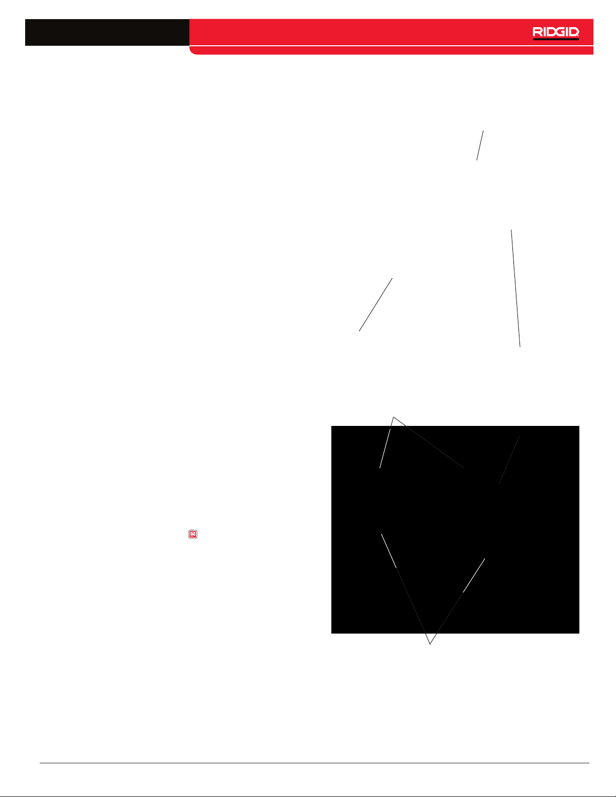
• Do not carry the Compact2 by the monitor’s dock-
ing handle or its front handle when transporting
the system long distances or under conditions
where disengagement of the docking system
would be hazardous. An unexpected disengagement
of the docking system may result in property damage
and/or injury.
• Placing the Compact2 where the drum cannot spin
freely may result in the push cable over-winding
inside the drum. Over-winding the push cable may re-
sult in property damage and/or serious injury. During
operation, place the Compact2 on a stable surface
and make sure the drum can spin freely.
• Operating the equipment while in water increas-
es the risk of electrical shock. Do not operate the
Compact2 if operator or equipment are standing in
water.
• The digital reporting monitor’s battery and other
electrical equipment and connections are not waterproof. Do not expose the equipment to wet loca-
tions.
• The equipment is not designed to provide high
voltage protection and isolation. Do not use where
a danger of high voltage contact is present.
• To prevent damage to the Compact2 and to de-
crease the risk of injury, do not expose the
Compact2 to mechanical shocks. Exposure to me-
chanical shocks can damage equipment and increase
the risk of serious injury.
6 – English
Find Quality Products Online at: [email protected]
www.GlobalTestSupply.com
Page 7

Product Overview
Description
The SeeSnake Compact2 camera reel offers fast, easy
setup and can take on the most diverse and demanding
inspection conditions. The Compact2 features a self-leveling camera at the end of a push cable stiff enough to
give you the power to push through small or restricted
pipes, yet flexible enough to make multiple tight turns.
The Compact2’s unique docking system gives you ultra-fast setup. Tilt the CS6Pak to the desired viewing
angle while docked or easily remove it from the dock for
convenient placement in your work area.
The CS6Pak is a compact, portable digital reporting monitor that you can use to capture audio, video, and photos
of your pipe inspections. When you use the CS6Pak with
the Compact2, you can deliver a USB drive containing
an automatically generated professional report of the inspection to your customer before leaving the premises.
The Compact2 has a 30m [100ft] long, friction-reducing
push cable and a 25mm [1in] self-leveling camera designed to inspect pipes ranging from 38mm to 152mm
[1.5in to 6in] in diameter, depending on pipe conditions.
Once a point of interest has been found in the pipe, use
the integrated 512Hz sonde and a receiver to locate its
position.
All SeeSnake monitors can connect to the Compact2 with
the SeeSnake system cable. The SeeSnake CS6Pak is
specifically designed to mount on the Compact2’s docking system for viewing ease, quick setup, and effortless transport. You can retrofit the SeeSnake MiniPak to
mount on the docking system with the Docking Handle
Kit, sold separately.
English – 7
Find Quality Products Online at: [email protected]
www.GlobalTestSupply.com
Page 8
Specifications
Weight 8kg [17lb]
Overall Dimensions
Length 625mm [25in]
Height 432mm [17in]
Width 360mm [14in]
Drum Diameter 432mm [17in]
Camera
Type Self-leveling
Length 38mm [1.5in]
Diameter 25mm [1in]
Light source 6 LEDs
Sonde 512Hz
Resolution
NTSC
656 × 492 pixels
PA L 768 × 576 pixels
Spring Assembly
Type Single
Length including camera 325mm [12.8in]
Push Cable
Length 30m [100ft]
Diameter 6mm [0.26in]
Fiberglass core diameter 3mm [0.14in]
Minimum bend radius 63mm [2.5in]
Pipe Capacity
§
38mm to 152mm
[1.5in to 6in]
System Cable Length 3m [10ft]
Operating Environment
Temperature ‡
Storage temperature
Ingress protection
without monitor
-10°C to 50°C
[14°F to 122°F]
-10°C to 70°C
[14°F to 158°F]
IP×5
Relative humidity 5 to 95 percent
Altitude 4,000m [13,120ft]
§ Actual pipe capacity depends on pipe conditions.
‡ While the camera can function in extreme temperatures,
some image quality changes may occur.
Standard Equipment
• SeeSnake Compact2
• Docking System
• Operator’s Manual
• Product Video
• Pipe Guide Kit
• Spanner Wrench
System Components
SeeSnake System Connector
Frame
SeeSnake System Cable
Frame Handle
Frame
Docking System
Cable Wraps
Drum
Serial Number Label
Rubber Feet
8 – English
Find Quality Products Online at: [email protected]
www.GlobalTestSupply.com
Page 9

Push Cable Guides
There are three push cable guides on the frame, one
inner guide and two outer guides. When using the
Compact2, the camera, spring, and push cable should
be threaded through all three guides.
Inner Push Cable Guide
Spring Clip
Spring Clip
On the outermost push cable guide, press the tab toward the outer edge of the push guide to lock open the
clip and free the camera spring. After the camera spring
is released, return the spring clip to the operation position. In the operation position, the spring clip helps guide
the push cable and secures the camera spring when it is
pushed back through the cable guides preventing it from
retracting back into the drum. The spring clip must be
in the operation position during transport to prevent the
camera spring from retracting back into the drum.
Operation Position
Locked Open
Only lock open the spring clip when you are routing the
camera. Keep the spring clip in the operation position
during normal use.
Camera Head
Outer Push Cable Guides
English – 9
Find Quality Products Online at: [email protected]
www.GlobalTestSupply.com
Page 10

Operating Instructions
WARNING
Routing the Camera
If the camera is inside the drum, you must route the
camera through the push cable guides. The push cable
and camera head should be threaded through all three
guides.
1. Lock open the spring clip.
Wear appropriate protective equipment such as
latex or rubber gloves, goggles, face shields, and
respirators when inspecting drains that might contain hazardous chemicals or bacteria. Always wear
eye protection to protect against dirt and other foreign objects.
Do not operate equipment if operator or equipment
are standing in water. Operating the equipment
while in water increases the risk of electrical shock.
Rubber-soled, non-slip shoes can help prevent slipping and electrical shock on wet surfaces.
Placement
Place the SeeSnake Compact2 and the CS6Pak near
the pipe entrance so you can manipulate the push cable
while viewing the display.
Placing the Compact2 where the drum cannot spin freely may result in the push cable over-winding inside the
drum. Over-winding the push cable may result in property damage and/or serious injury. During operation, place
the Compact2 in a stable location and make sure the
drum can spin freely. Do not pull the push cable out of
the drum unless the drum can spin freely.
2. Reach inside the drum and find the camera.
3. Insert the camera through the inner push cable guide
and then through the two outer push cable guides.
4. Return the spring clip to the operation position to secure the spring and prevent the push cable from retracting back into the drum.
10 – English
Find Quality Products Online at: [email protected]
www.GlobalTestSupply.com
Page 11
Docking System
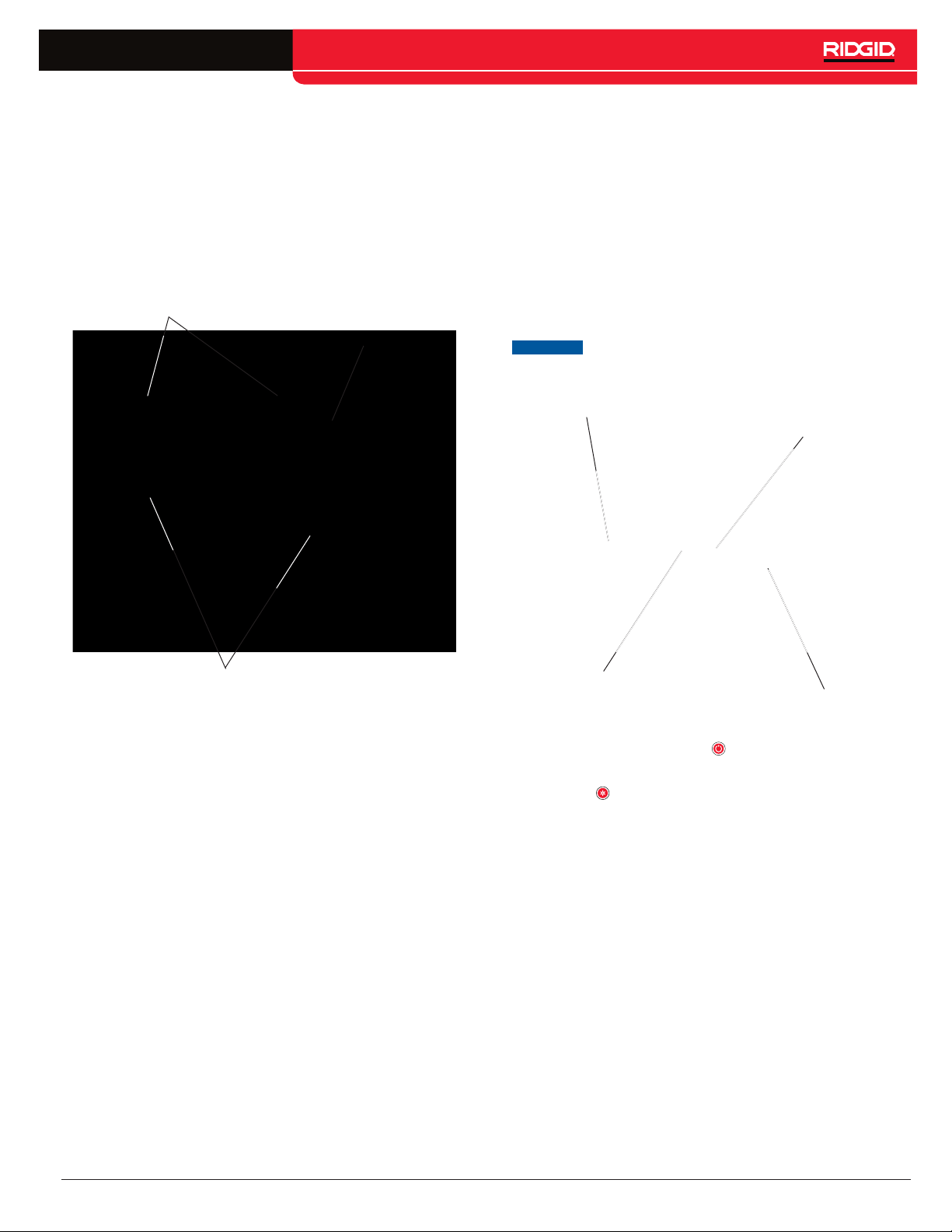
The Compact2 comes with a docking system assembly
installed so that a compatible monitor can be mounted
onto the reel for easy transport. Tilt the docked monitor
to the desired viewing angle or easily remove it from the
dock for convenient placement in your work area. The
docking system assembly is removable.
Note: Refer to the Docking System section for instructions on how to mount and remove a compatible monitor.
Joint Sockets
Quick-Release Knob
Connecting to a SeeSnake Monitor
The Compact2 can connect to any SeeSnake monitor
with the SeeSnake system cable.
1. Unwrap the system cable from the cable wraps.
2. Pull back the outer locking sleeve on the system
cable connector.
3. Align the connector ridge and plastic guide pin with
the socket and push the connector straight in.
4. Tighten the outer locking sleeve.
NOTICE
Connector Ridge
Only twist the outer locking sleeve. To
prevent damage to the pins, never bend
or twist the connector.
Guide Pin
Docking Fins
Outer Locking Sleeve
Socket
5. Power on the system:
• Press the Power key to power on the system.
• On a digital reporting monitor, press the Autolog
key to quick-start an inspection.
Note: For some digital reporting monitors, a USB drive
must be inserted to capture media. Refer to the monitor’s manual for more information about the benefits of
Autolog video recordings.
English – 11
Find Quality Products Online at: [email protected]
www.GlobalTestSupply.com
Page 12
Inspection Overview
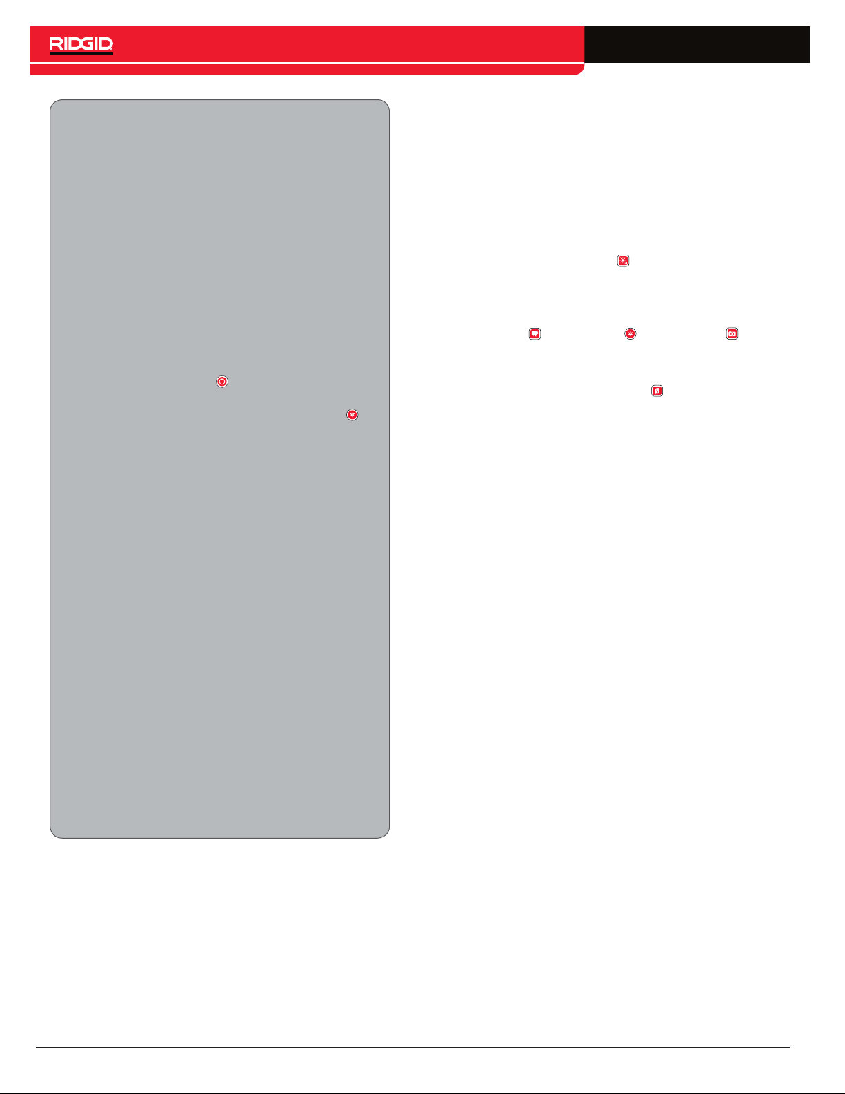
The SeeSnake Compact2 can be used for basic
or advanced pipe inspections. To perform a basic
inspection, connect any SeeSnake monitor to the
Compact2, power on the system, push the push
cable through the pipe, and observe the display. An
advanced inspection requires a SeeSnake digital
reporting monitor and additionally involves capturing media and delivering reports to your customer.
1. Place the Compact2 near the pipe entrance.
Make sure the system is stable and the drum
can spin freely.
2. Connect the system cable to the digital reporting monitor.
3. Press the Power key to power on the system.
Alternatively, insert a USB drive into the monitor’s USB port and press the Autolog key to
quick-start the inspection.
4. Release the spring clip and, if desired, install a
pipe guide or camera head guide to keep the
camera centered in the pipe. Make sure the
camera lens is clean.
5. Carefully put the camera into the pipe. Protect
the push cable from sharp edges at the pipe
entrance.
Advanced Options
Both basic and advanced pipe inspections can include
taking pipe segment distance measurements, adjusting
the camera’s LED brightness, or activating the sonde.
Depending on your digital reporting monitor’s features,
you may also want to capture media and create reports.
Note: Refer to your digital reporting monitor manual for
instructions on capturing media and creating reports.
• Press the Brightness key to turn up the brightness
of the camera LEDs so you can see further down
the pipe.
• Capture media of the inspection by pressing the
Video key , Autolog key , or Photo key . If you
are using a CS6Pak, you must insert a USB drive
prior to capturing media.
• Press and hold the Zero key for three seconds
to set the system zero point wherever you want to
begin counting from.
• Use a RIDGID SeekTech locating receiver to locate
a point of interest with the integrated 512Hz sonde.
• Use a RIDGID SeekTech locating receiver with a
transmitter to find the path of a pipe by line tracing
the push cable.
6. Push the camera through the pipe and observe
the display.
7. Advanced Options:
• Set the system zero point, or take a temporary segment distance measurement.
• Capture media.
• Create on-screen custom overlay.
• Locate an inspection point or path.
• Create and deliver an inspection report to
your customer on a USB drive.
8. When the inspection is complete, retrieve the
camera and secure the spring in the spring clip.
12 – English
Find Quality Products Online at: [email protected]
www.GlobalTestSupply.com
Page 13

Best Practices
Refer to the following tips and recommendations to
perform the pipe inspection with efficiency and ease.
Following these tips can increase the longevity and effectiveness of your equipment and prevent damage.
• Run water through the pipe during the inspec-
tion to keep the camera system clean, make
pushing the push cable easier, and allow longer
pushes. Place a hose down the pipe or turn on
a fixture. Shut off the water flow as needed for a
clear view.
• Apply a thin film of liquid detergent or soap on the
camera to help keep the lens clear.
• Be careful when inspecting porcelain appliances.
The camera may scratch the surface finish.
• Sharp edges at the pipe entrance can cut, kink,
snag, or damage the push cable. Use extreme care
and always keep one hand near the pipe entrance
when pushing into the pipe to avoid damaging the
push cable.
• Use rubber gripper-type gloves to manipulate the
push cable, improve grip, and keep hands clean.
Use a quick push to pop the camera around a bend
such as a p-trap, tee, Y, or elbow. To pop around a
bend, pull the camera back approximately 200mm
[8in] and thrust it through in one motion. Do not use
more force than is necessary.
• Some inspection conditions can cause the spring to
fold back so that the camera faces the wrong way.
If the push cable is visible on the display, the spring
has folded over on itself. Pull the push cable back. If
necessary, pull the push cable all the way out of the
pipe and attempt the inspection again.
• To keep the push cable from folding over on itself,
only push short sections through the pipe at a time.
If the push cable folds over on itself, it can snap or
kink.
• Obstructions or excessive build up in the pipe can
damage or prevent retrieval of the camera. Do not
use the camera to clear obstructions.
• The video image is most stable and clear when moving the push cable backward in the pipe. When you
have found an area of interest in the pipe, push the
camera beyond it and then pull back.
• Dragging the push cable over sharp edges can damage the push cable. Do not drag the push cable over
sharp edges and do not pull or bend the push cable
at sharp angles at the pipe entrance.
English – 13
Find Quality Products Online at: [email protected]
www.GlobalTestSupply.com
Page 14

Pipe Guides
Pipe guides center the camera in the pipe, improve
picture quality, and help keep the lens clear. Use pipe
guides when possible to reduce wear and tear on the
camera system.
Pipe guides can easily be installed, adjusted, and removed to provide better camera and push cable movement in the pipe. For small pipes, tubes, or voids, the
camera head guide helps push the camera through stubborn fittings. For larger pipes, ball guides center the camera for better visibility and light illumination.
Camera Head Guide Installation
The 36mm [1.4in] camera head guide can be used in
smaller pipes to push the camera through stubborn fittings.
1. Loosen the screws on both sides of the guide until it
slides easily onto the camera head.
2. Re-secure the screws until the guide stays in place,
but do not over-tighten.
Without Pipe Guide
With Pipe Guide
14 – English
Find Quality Products Online at: [email protected]
www.GlobalTestSupply.com
Page 15

Ball Guide Installation
Ball guides are designed to slip onto the spring and lock
into place. Depending on work conditions, you can place
a ball guide on the spring behind the camera to tilt the
camera head upward to view the top of the pipe.
1. Make sure the ball guide is unlocked.
2. Slide the ball guide beyond the camera on to the
spring.
Locating the Sonde
You can use the integrated sonde to locate a point of interest in the pipe at any time during the inspection. The
sonde is located in the spring and is assembled between
the end of the push cable and the camera. The sonde
transmits a locatable 512 Hz signal that can be detected by receivers such as the RIDGID SeekTech SR-20,
SR-24, SR-60, Scout™, or NaviTrack® II.
Press the Sonde key to enable and disable the sonde.
When the sonde is enabled, the LED by the key is lit and
the sonde icon displays on the screen. The 512Hz
sonde signal can cause interference lines that may be
visible on captured media.
3. Press down on the blue locks to secure the ball guide
onto the spring.
4. Slide the red locks over the blue locks to secure the
ball guide into place.
Locked
NOTICE
If a ball guide gets snagged in a pipe, it
can fall off the spring. To avoid losing
ball guides and obstructing the pipe, do
not use excessive force to push through
the pipe when you feel resistance.
Unlocked
To locate the sonde, follow these steps:
1. Power on the receiver and set it to sonde mode.
2. Locate the sonde’s general direction so you know
which way the pipe goes:
• Power on the sonde and push the push cable no
more than 5m [15ft] into the pipe.
• Sweep the horizon with the receiver in a slow
arc.
3. The signal strength is highest where the receiver detects the sonde.
Note: For additional instructions on sonde locating, refer
to the manual for the receiver model you are using.
English – 15
Find Quality Products Online at: [email protected]
www.GlobalTestSupply.com
Page 16

Line Tracing the Push Cable
You can locate the path of a pipe by line tracing the push
cable. This is especially useful for inspecting non-metallic or non-conductive pipes. Line trace the push cable by
using a tranceiver to induce current onto the push cable
using a transmitter.
Retrieving the Camera
After completing the inspection, pull the push cable back
out of the pipe with slow, steady force and return it to the
drum. Wipe the push cable with a paper towel or cloth as
you withdraw it. If possible, continue running water down
the pipe to clean the push cable.
To line trace the push cable, follow these steps:
1. Push the transmitter’s ground stake into the ground
and clip one of the transmitter’s leads to it.
2. Clip the other lead to the transmitter clip-on terminal
on the back of the monitor.
3. Power on the transmitter and set your desired frequency. For best results, use frequencies 33 kHz
and higher.
4. Power on the receiver and set it to the same frequency as the transmitter.
To avoid damage to the camera or push cable, do not
exert excessive force during retrieval. If the camera head
is stuck behind a turn, you can pop the camera past the
turn or run water down the pipe to lubricate the push
cable.
NOTICE
Gripping close to the Compact2, always
use short strokes to feed back small
lengths of the push cable into the drum.
Pushing back longer lengths of the push
cable or forcing the push cable may
cause it to loop, kink, or break.
5. Trace the line.
Note: For additional instructions on line tracing, refer to
the manual for the transmitter and receiver models you
are using.
16 – English
Find Quality Products Online at: [email protected]
www.GlobalTestSupply.com
Page 17
Individual Components
Self-Leveling Camera
The bearings and weight of the self-leveling camera may
create a swinging effect when you push the push cable
through the pipe. The camera image settles quickly when
the push cable is steady.
The self-leveling camera can be removed to troubleshoot problems, send for repair, or to replace. Refer to
Appendices C and D for instructions on how to remove
and install the camera head.
System Cable Assembly
The system cable assembly includes the system connector, for connecting to SeeSnake digital reporting monitors; 3m [10ft] of system cable; and the slip-ring assembly, which is made up of the slip-ring dial and the slip-ring
cavity on the frame.
Before cleaning the Compact2, ensure the slip-ring dial
is locked in the slip-ring cavity. Avoid getting the slipring assembly wet when cleaning.
NOTICE
To avoid damaging the slip-ring contact
pins or getting the internal electrical
components wet, keep the slip-ring assembly locked.
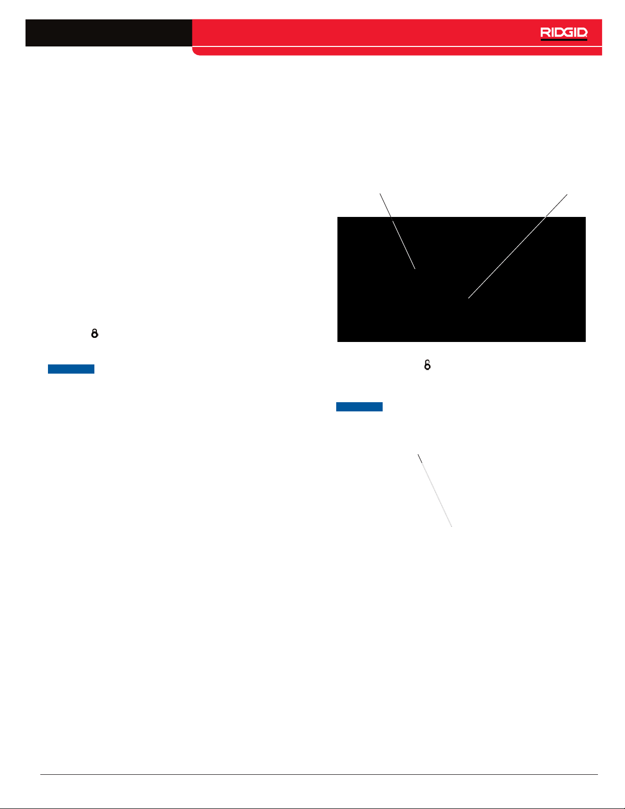
System Cable Removal
1. Disconnect the system cable from the reporting
monitor and remove the monitor from the docking
system.
2. Unwrap the system cable from the cable wraps.
3. Pop the frame cable anchor off the frame and unhook the system cable from the frame hook.
Cable Anchor
4. Turn the slip-ring dial counter-clockwise to the unlocked position .
5. Pull straight out.
NOTICE
Do not touch the contact pins inside the
slip-ring dial. Stressing the contact pins
can cause them to break.
Frame Hook
Broken Contact Pin
English – 17
Find Quality Products Online at: [email protected]
www.GlobalTestSupply.com
Page 18
System Cable Installation
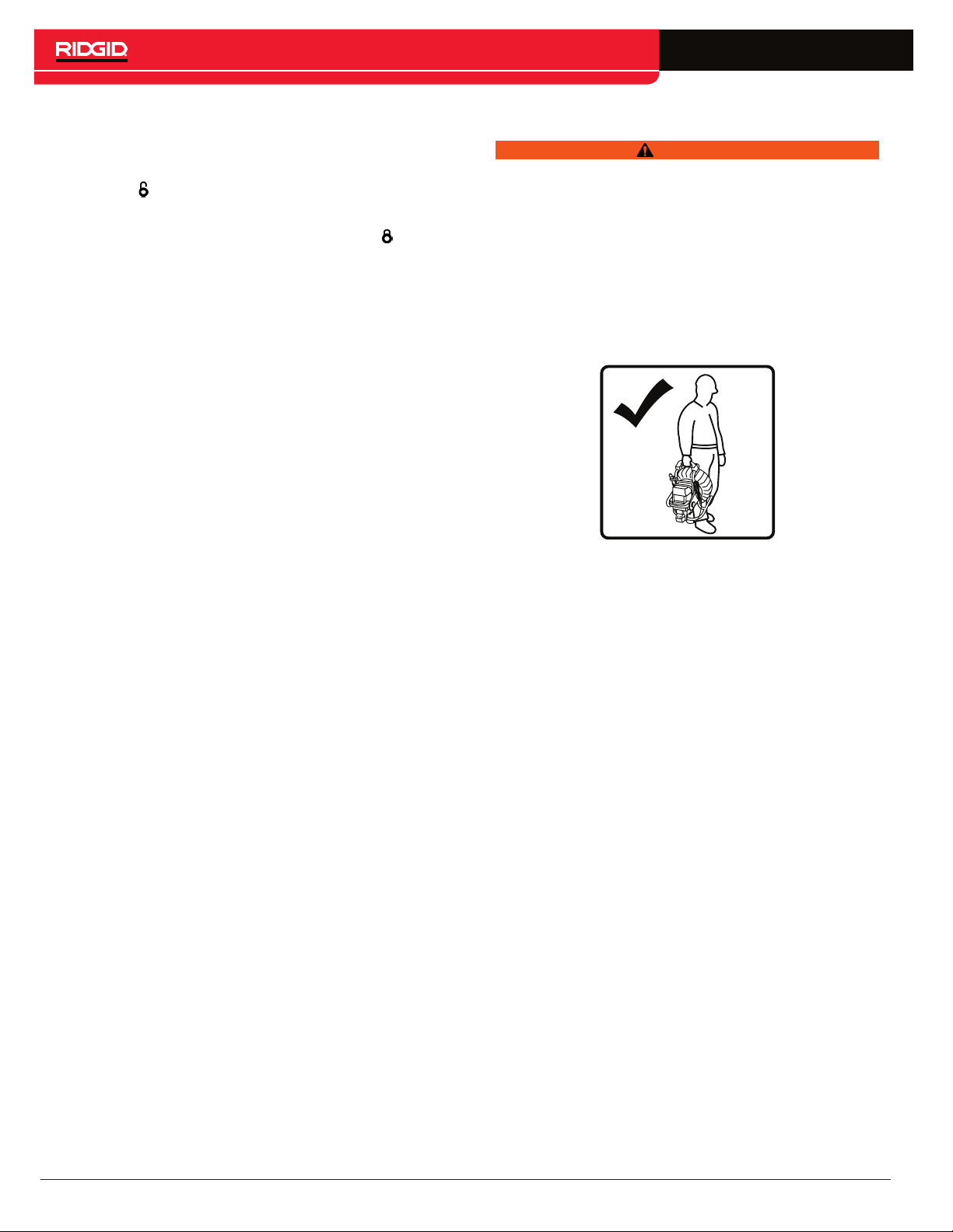
To install the system cable, follow these steps:
1. Align the arrow on the slip-ring dial with the unlock
symbol on the frame and insert the slip-ring dial
into the slip-ring cavity.
2. Turn the slip-ring dial to the locked position .
Docking System
WARNING
Carrying the system incorrectly can cause the monitor’s docking handle to disengage from the docking
system and may result in property damage and/or
serious injury.
Do not carry the Compact2 by the monitor’s docking
handle or its front handle when transporting the system long distances or under conditions where disengagement of the docking system would be hazardous.
3. Hook the system cable into the frame hook and snap
the cable anchor onto the frame.
4. Wrap the system cable around the cable wraps.
The docking system gives you flexibility with its tilt feature
and quick-release knobs. Tilt the digital reporting monitor to any angle for viewing ease or release the CS6Pak
from the docking system with the quick-release knobs
and place it somewhere more convenient.
18 – English
Find Quality Products Online at: [email protected]
www.GlobalTestSupply.com
Page 19
Mounting the Monitor
1. Turn the docking joints on sides of the docking handle so that the openings point down.
Docking Handle
Front Handle
Docking Joint
2. Center the CS6Pak over the docking fins and align
the docking joints with the joint sockets on the docking fins.
The SeeSnake CS6Pak is specifically designed to mount
onto the Compact2 and is sold with a compatible docking
handle installed. The Compact2 can also be used with a
retrofitted SeeSnake MiniPak using the Docking Handle
Kit, sold separately.
To make using the setup pictured bottom right most practical, press the Image Flip key
seconds to rotate the user interface. Repeat to return the
screen to its normal viewing mode.
Note: Refer to the Docking Handle Kit for instructions on
how to install the docking handle.
on the CS6Pak for 3
Joint Sockets
Quick-Release Knob
Docking Fins
3. Firmly push the monitor down into the docking system until you feel the monitor lock into place.
English – 19
Find Quality Products Online at: [email protected]
www.GlobalTestSupply.com
Page 20

Removing the Monitor
1. Place the Compact2 so you can grasp both quick-release knobs.
Maintenance and Support
Maintaining Components
2. Pull both knobs out and away from the docking fins.
In the same motion as pulling the knobs out, turn
the knobs together in either direction to disengage
the locks.
Note: The locks are disengaged when the yellow indicator labels are visible under the knobs.
Yellow Indicator Label
3. Grip the docking handle and pull the digital reporting
monitor straight up.
Camera Head
The camera head requires little maintenance other than
keeping the LED ring and sapphire window clean. Use
a soft nylon brush, mild detergent, and rags to clean the
camera.
Scraping tools may permanently scratch the camera.
Scratches on the LED ring have a minimal effect on the
camera’s performance.
NOTICE
Do not sand the LED ring to remove scratches. Sanding the LED ring can damage the
watertight housing.
Spring
Stretch the spring end-to-end as far as it allows so you
can visually inspect the inner components. Stir the spring
in lukewarm water and a mild detergent to flush away debris.
Push Cable
Keep the push cable clean. Run a rag over the push
cable as it goes back into the drum after each inspection
to clean it and reduce debris accumulation.
Visually inspect the push cable for cuts and abrasions
while pushing it back into the drum. Replace or repair the
push cable if the outer jacket is cut or abraded.
20 – English
Find Quality Products Online at: [email protected]
www.GlobalTestSupply.com
Page 21

Cleaning
For light cleaning, use a soft, damp cloth to wipe down
the Compact2. If desired, you can use a disinfectant.
NOTICE
To thoroughly clean the Compact2, follow these steps:
1. Prepare:
2. Stand the Compact2 upright and pour lukewarm
water and a mild detergent into the drum.
Using solvents to clean any part of the
system can affect waterproofing.
• Disconnect the system cable from the digital reporting monitor and remove the monitor from the
docking system.
• Make sure the slip-ring dial is in the locked
position.
• Push the camera through all three push cable
guides and into the drum so the drum can spin
freely.
3. Spin the drum to loosen the debris.
4. Tip the drum opening down to empty the water.
5. In a large area, pull the push cable through the
guides and completely out of the drum. Do not try to
coil the push cable outside of the drum.
6. Use a hose to clean the empty drum.
7. Fully dry the Compact2. Run a rag over the push
cable while you push it back into the drum.
NOTICE
Find Quality Products Online at: [email protected]
High pressure water can damage the
seals that protect the electronics inside
the drum.
English – 21
www.GlobalTestSupply.com
Page 22

Accessories
Service and Repair
Only use accessories specifically designed and recommended for use with the SeeSnake Compact2.
Accessories designed for use with other tools may
become hazardous when used with the Compact2.
The following RIDGID products have been designed to
function with the Compact2:
• Pipe Guide Kit
• Docking Handle Kit
• Shoulder Strap
• RIDGID SeekTech or NaviTrack Receivers
• RIDGID SeekTech or NaviTrack Transmitters
• RIDGID SeeSnake Digital Reporting Monitors
• RIDGID SeeSnake Original Monitors
Transport and Storage
Store and transport your equipment with the following in
mind:
• Store in a locked area out of the reach of children
and people unfamiliar with its purpose.
Improper service or repair can cause the SeeSnake
Compact2 to be unsafe to operate.
Service and repair of the Compact2 must be performed
at a RIDGID Independent Authorized Service Center. To
maintain the safety of the tool, make sure a qualified repair person services your equipment using only identical replacement parts. Discontinue using the Compact2
and contact service personnel under any of the following
conditions:
• If liquid has been spilled or objects have fallen into
the equipment.
• If the equipment does not operate normally when
operating instructions are followed.
• If the equipment has been dropped or damaged.
• If the equipment exhibits a distinct change in performance.
• Store in a dry place to reduce risk of electrical shock.
• Store away from heat sources such as radiators,
heat registers, stoves, and other products (including
amplifiers) that produce heat.
• Storage temperature should be -10°C to 70°C [14°F
to 158°F].
• Do not expose to heavy shocks or impacts during
transport.
Disposal
Parts of the SeeSnake Compact2 contain valuable materials that can be recycled. Dispose of the components in
compliance with all applicable regulations. Contact your
local waste management authority for more information.
For EC countries: Do not dispose of electrical equipment with household waste!
According to the European Guideline 2002/
96/EC for Waste Electrical and Electronic
Equipment and its implementation into national legislation, electrical equipment that is no longer usable must be collected separately and disposed of in an
environmentally correct manner.
22 – English
Find Quality Products Online at: [email protected]
www.GlobalTestSupply.com
Page 23
Troubleshooting
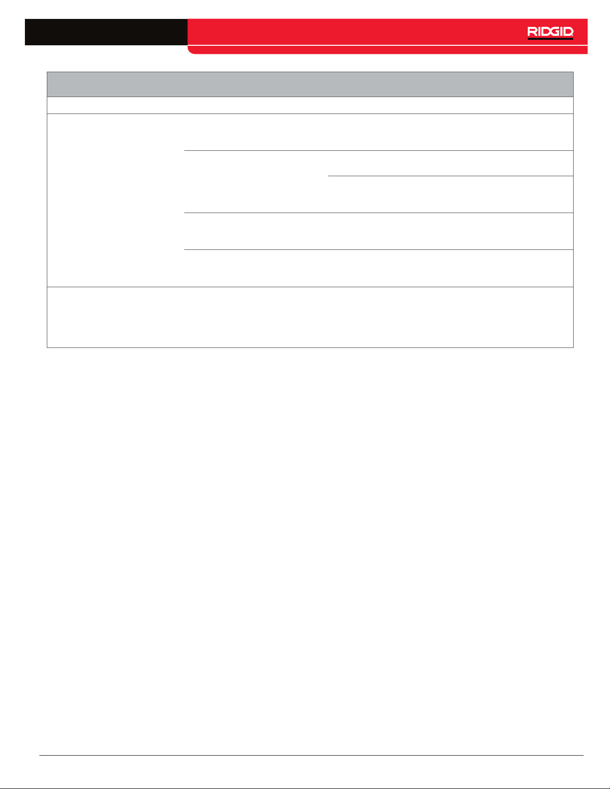
Problem Probable Fault Solution
No video feedback
No count measurement
No power to the SeeSnake
monitor.
Slip-ring assembly is broken
or the connection is faulty.
SeeSnake system cable
connection is faulty.
Camera is faulty.
Older SeeSnake monitors
may not be compatible with
the Compact2’s integrated
counter.
Check to make sure the power source is properly
connected.
Check all alignment and connection pins.
Check placement and pin condition in the slip-ring
assembly.
Check SeeSnake system cable connection. Make
sure the connectors are pushed all the way in.
Isolate the fault to the camera. Refer to Appendix B
for instructions.
Count measurements will show up on job reports,
and may show up on the monitor during viewing.
A new monitor may be required if capturing count
measurements to media is necessary.
English – 23
Find Quality Products Online at: [email protected]
www.GlobalTestSupply.com
Page 24

Appendices
Appendix A: Docking Fin Removal
If you are using the Compact2 with a monitor that does
not mount onto the docking system, you can remove the
docking fins for easier transport and storage.
1. Unscrew all twelve screws with a Phillips screwdriver
from one of the docking fins.
2. Pull apart the fin plates and remove them from the
frame.
Appendix B: Camera Fault Isolation
1. Remove the camera from the push cable.
Note: Refer to Appendix C for instructions on how to
remove the camera.
2. Plug the camera directly into the monitor’s system
cable socket.
3. Press the Power key to power on the system.
Make sure there is video feedback and the LED
lights flash.
• If there is video feedback and the LED lights
flash, the camera is working properly.
• If there is no video feedback or if the LED lights
do not flash, the camera is at fault.
3. Repeat the same steps for the other side.
24 – English
Find Quality Products Online at: [email protected]
www.GlobalTestSupply.com
Page 25

Appendix C: Camera Removal
1. Snap the included spanner wrench onto the spring,
just behind the camera.
2. Align the notch inside the spanner wrench with the
end of the spring coil.
4. Unscrew the locking sleeve from the camera.
5. Pull the camera straight out of the sonde’s socket.
3. Unscrew the spring from the camera.
NOTICE
To avoid damaging the camera’s connec-
tor pins, do not bend or twist while pulling the camera out of the connector.
English – 25
Find Quality Products Online at: [email protected]
www.GlobalTestSupply.com
Page 26

Appendix D: Camera Installation
1. Align the camera head pins with the sonde’s socket
and push together.
4. The sonde will twist when you thread the camera
onto the spring. Rotate the camera one turn counterclockwise to counteract the twisting and then thread
onto the spring.
2. Slide push cable locking sleeve onto the camera.
3. To make sure the safety cables end up relatively
straight when you screw the camera onto the spring,
back-twist the camera by approximately 1 ½ turns
(counter-clockwise).
5. Thread the spring onto the camera until the end of
the spring is flush against the camera head.
NOTICE
Do not over-tighten the spring.
Over-Tightened Spring
26 – English
Find Quality Products Online at: [email protected]
www.GlobalTestSupply.com
 Loading...