

Page 1
KJ-2200/KJ-3100 Water
Jetting Machine
s
• Français – 19
• Castellano – pág. 31
WARNING!
Read this Operator’s Manual
carefully before using this
tool. Failure to understand
and follow the contents of
this manual may result in
electrical shock, fire and/or
serious personal injury.
Water Jetter Manual
Find Quality Products Online at: [email protected]
www.GlobalTestSupply.com
Page 2

Table of Contents
Recording Form For Machine Serial Number .............................................................................................................1
Safety Symbols..............................................................................................................................................................2
General Safety Rules
Work Area Safety ........................................................................................................................................................2
Electrical Safety...........................................................................................................................................................2
Personal Safety ...........................................................................................................................................................2
Tool Use and Care ......................................................................................................................................................2
Service ........................................................................................................................................................................3
Water Jetter Safety Warnings.......................................................................................................................................3
Description, Specifications and Standard Equipment
Description ..................................................................................................................................................................4
Specifications ..............................................................................................................................................................4
Icons............................................................................................................................................................................5
Standard Equipment....................................................................................................................................................5
Machine Assembly
Engine Oil....................................................................................................................................................................5
Pump/Gearbox Oil.......................................................................................................................................................5
KJ-2000 Transport Cart...............................................................................................................................................5
KJ-3100 Handle Assembly ..........................................................................................................................................5
Pre-Operation Inspection..............................................................................................................................................6
Machine and Work Area Set Up ...................................................................................................................................7
Water Supply...............................................................................................................................................................8
Drain Preparation ........................................................................................................................................................9
Hose Set-Up................................................................................................................................................................9
Jetter Hose Selection Chart ......................................................................................................................................10
Jetter Nozzle Selection Chart....................................................................................................................................10
Operating Instructions ................................................................................................................................................11
Jetting The Drain .......................................................................................................................................................12
Using The Pulse Mode ..............................................................................................................................................13
Using Water Jetter Machine as a Pressure Washer .................................................................................................13
Pressure Washer Operation......................................................................................................................................14
Detergent Injector......................................................................................................................................................14
Maintenance Instructions
Cleaning ....................................................................................................................................................................14
Engine .......................................................................................................................................................................15
Pump Lubrication ......................................................................................................................................................15
Gearbox Lubrication ..................................................................................................................................................15
Preparing Pump for Cold Weather Storage...............................................................................................................15
Accessories .................................................................................................................................................................15
Machine Storage..........................................................................................................................................................16
Service And Repair......................................................................................................................................................16
Disposal........................................................................................................................................................................16
Troubleshooting ..........................................................................................................................................................17
Lifetime Warranty..........................................................................................................................................Back Cover
*Original Instructions - English
ii
KJ-2200/KJ-3100 Water Jetter Machines
Find Quality Products Online at: [email protected]
www.GlobalTestSupply.com
Page 3
KJ-2200/KJ-3100 Water
Jetting Machines
Water Jetter
KJ-2200/KJ-3100 Water Jetting Machines
Record Serial Number below and retain product serial number which is located on nameplate.
Serial
No.
KJ-3100
KJ-2200
Find Quality Products Online at: [email protected]
www.GlobalTestSupply.com
Page 4
2
KJ-2200/KJ-3100 Water Jetting Machines
General Safety Rules
WARNING
Read and understand all instructions. Failure to follow all instructions listed below may result in electric shock, fire, and/or serious injury.
SAVE THESE INSTRUCTIONS!
Work Area Safety
• Keep work area clean and well lit. Cluttered benches
and dark areas invite accidents.
• Do not operate power tools in explosive atmo-
spheres, such as in the presence of flammable
liquids, gases, or dust. Power tools create sparks
which may ignite the dust or fumes.
• Keep bystanders, children, and visitors away while
operating a power tool. Distractions can cause you to
lose control.
Electrical Safety
• Avoid body contact with grounded surfaces such
as pipes, radiators, ranges and refrigerators. There
is an increased risk of electric shock if your body is
grounded.
Personal Safety
• Stay alert, watch what you are doing and use common sense when operating a power tool. Do not
use a tool while you are tired or under the influence
of drugs, alcohol or medication. A moment of inat-
tention while operating power tools may result in serious personal injury.
• Dress properly. Do not wear loose clothing or jew-
elry. Contain long hair. Keep your hair, clothing and
gloves away from moving parts. Loose clothes, jew-
elry or long hair can be caught in moving parts.
• Do not overreach. Keep proper footing and bal-
ance at all times. Proper footing and balance enables better control of the tool in unexpected situations.
• Use safety equipment. Always wear eye protec-
tion. Dust mask, non-skid safety shoes, hard hat, or
hearing protection must be used for appropriate conditions will reduce personal injuries.
Tool Use and Care
• Do not force the tool. Use the correct tool for your
application. The correct tool will do the job better and
safer at the rate for which it was designed.
• Do not use the power tool if the switch does not turn
Safety Symbols
In this operator’s manual and on the product, safety symbols and signal words are used to communicate important safety
information. This section is provided to improve understanding of these signal words and symbols.
This is the safety alert symbol. It is used to alert you to potential personal injury hazards. Obey all safety messages that follow this
symbol to avoid possible injury or death.
DANGER indicates a hazardous situation which, if not avoided, will result in death or serious injury.
WARNING indicates a hazardous situation which, if not avoided, could result in death or serious injury.
CAUTION indicates a hazardous situation which, if not avoided, could result in minor or moderate injury.
NOTICE indicates information that relates to the protection of property.
This symbol means read the operator’s manual carefully before using the equipment to reduce the risk of injury. The operator’s
manual contains important information on the safe and proper operation of the equipment.
This symbol means always wear safety glasses with side shields or goggles when handling or using this equipment to reduce
the risk of eye injury.
NOTICE
This symbol indicates the risk of high pressure water directed at body parts, causing skin puncture and injection injuries.
This symbol indicates the risk of the jetter hose whipping, and causing striking or injection injuries.
DANGER
WARNING
CAUTION
This symbol indicates the risk of breathing carbon monoxide and causing nausea, fainting or death.
This symbol indicates the risk of fire and explosion from gasoline or other sources causing burns and other injury.
Find Quality Products Online at: [email protected]
www.GlobalTestSupply.com
Page 5
3
it ON and OFF. Any tool that cannot be controlled with
the switch is dangerous and must be repaired.
• Store idle tools out of the reach of children and
other untrained persons. Tools are dangerous in
the hands of untrained users.
• Maintain tools with care. Keep cutting tools sharp
and clean. Properly maintained tools with sharp cutting
edges are less likely to bind and are easier to control.
• Check for misalignment or binding of moving parts,
breakage of parts and any other condition that
may affect the tool’s operation. If damaged, have the
tool serviced before using. Many accidents are
caused by poorly maintained tools.
• Use only accessories that are recommended by the
manufacturer for your model. Accessories that may
be suitable for one tool, may become hazardous when
used on another tool.
Service
• Tool service must be performed only by qualified
repair personnel. Service or maintenance performed
by unqualified personnel could result in a risk of injury.
• When servicing a tool, use only identical replace-
ment parts. Follow instructions in the Maintenance
section of this manual. Use of unauthorized parts or
failure to follow Maintenance Instructions may create a
risk of electrical shock or injury.
Water Jetter Safety Warnings
WARNING
This section contains important safety information
that is specific to this tool.
Read these precautions carefully before using this
Drain Cleaning Machine to reduce the risk of electrical shock or other serious personal injury.
SAVE ALL WARNINGS AND INSTRUCTIONS
FOR FUTURE REFERENCE!
Keep this manual with the machine for use by the operator.
• Never operate the jetter with the hose end out-
side of the drain. Hose can whip, causing striking
injuries and spray can penetrate skin and cause serious
injury.
• High pressure water can inject under skin result-
ing in serious injury including amputation. Do
not direct spray at people or animals.
• Do not operate jetter above pressure rating or
140°F (inlet water temperature). This increases the
KJ-2200/KJ-3100 Water Jetting Machines
risk of injury, including burns, and damage to the jetter.
• One person must control both the jetting process
and the foot valve. Always use the foot valve. If the
jetter hose comes out of the drain, the operator must be
able to shut the water flow off to reduce the risk of the
jetter hose whipping, causing striking and high pressure
injection injuries.
• Always use appropriate personal protective equip-
ment while handling and using drain cleaning equipment. Drain may contain chemicals, bacteria and other
substances that may be toxic, infectious, cause burns or
other issues. Appropriate personal protective equipment always includes safety glasses and gloves, and
may also include equipment such as latex or rubber
gloves, face shields, goggles, protective clothing, respirators, and steel toed footwear.
• Practice good hygiene. Use hot soapy water to
wash hands and other body parts exposed to drain
contents after handling or using drain cleaning
equipment. Do not eat or smoke while operating or
handling drain cleaning equipment. This will help prevent contamination with toxic or infectious material.
• Do not spray toxic or flammable liquids. This will re-
duce the risk of burns, fire, explosion or other injury.
• Gasoline and its vapors are highly flammable and
explosive. See engine manual for precautions to reduce the risk of burns, explosions and serious injury
while handling and using gasoline.
• Engines produce carbon monoxide, a colorless,
odorless poison gas. Breathing carbon monoxide
can cause nausea, fainting or death. Do not start and
run engine in an enclosed area, even if doors and
windows are open. Only operate outside.
• Hot surfaces can cause burns and fire. Keep body
parts and flammable material away from hot surfaces.
• Read and understand this manual, the engine man-
ual and the warnings and instructions for all equipment being used with this tool before operating.
Failure to follow all warnings and instructions may result
in property damage and/or serious injury.
The EC Declaration of Conformity (890-011-320.10) will
accompany this manual as a separate booklet when required.
If you have any question concerning this RIDGID®product:
Find Quality Products Online at: [email protected]
www.GlobalTestSupply.com
Page 6

4
KJ-2200/KJ-3100 Water Jetting Machines
Figure 2 – KJ-3100 Water Jetting Machine
Figure 3 – Machine Serial Number
The machine serial number is located on the frame. The
last 4 digits indicate the month and year of the manufacture. (08 = month, 10 = year).
Description, Specifications and
Standard Equipment
Description
The RIDGID®Engine Powered Water Jetting Machines are
portable high pressure water jetters designed to use a
combination of water pressure and flow to clear grease,
sludge, sediment and roots out of drains. A highly flexible
and lightweight hose is propelled through the drain by
the reverse jets on the jetter nozzle, and when retrieved
scrubs the line flushing debris away. With the pulse activation engaged, difficult bends and traps are more easily
negotiated. All machines are equipped with a gasoline engine to drive the triplex plunger pump.
Figure 1 – KJ-2200 Water Jetting Machine
Handle
Engine Switch
Engine Pump
Specifications
Jetter Motor Pressure Flow Rate Drain Line Weight (lbs)
Model H.P. (PSI) (GPM) Capacity (w/o Hose Reel)
KJ-2200 6.5 2200 2.4 11/4" - 6" 65 (30 kg)
KJ-3100 16 3000 5.5 2" - 10" 262 (119 kg)
Pump
Manual Holder
Handles
Engine
Foot Switch
Date Code
Reel
Hose
Foot Switch
Hose
Reel
Find Quality Products Online at: [email protected]
www.GlobalTestSupply.com
Page 7
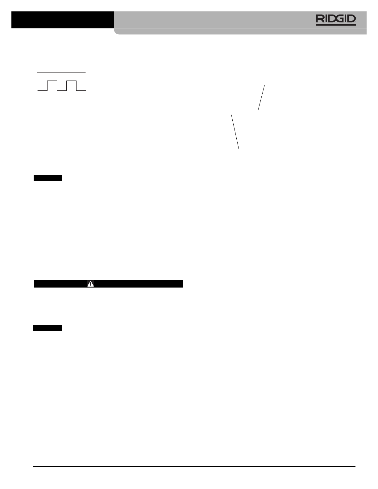
Icons
Standard Equipment
All Jetters come with
• Appropriate Jetter Nozzles
• Nozzle Cleaning Tool
• FV-1 Foot Valve
• Engine Operator’s Manual
See the RIDGID catalog for specific equipment supplied with each catalog number.
This machine is made to clean drains. If properly used it will not damage a drain that is in good condition and properly designed, constructed and
maintained. If the drain is in poor condition or not properly designed, constructed or maintained, the drain
cleaning process may not be effective or could cause
damage to the drain. The best way to determine the condition of a drain before cleaning is through visual inspection with a camera. Improper use of this jetting
machine can damage the jetter and the drain. This machine may not clear all blockages.
Machine Assembly
WARNING
To prevent serious injury during use and prevent
machine damage, follow these procedures for proper
assembly.
Engine Oil
Jetter is shipped without oil in the engine.
Operating the engine without oil will result in engine
failure. Add oil prior to operation. See supplied engine
operator’s manual for specific information on adding oil
and oil selection.
Pump/Gearbox Oil
Pump: Replace the plug in the top of the pump and replace with dipstick/breather cap. Operating the jetter
with the plug in place could damage the pump seals.
Check oil level per
Maintenance Instruction
section.
Gearbox (KJ-3100 only): Replace the plug in the top of
the pump with dipstick/breather cap. Oper ating the jetter
with the plug in place could damage the gearbox seals.
Check lubricant level per the
Maintenance Instruction
section.
Figure 4 – Assembly of the KJ-2200
KJ-2200 Transport Cart
1. Install retaining clip into inner groove on each end of
axle.
(See Figure 4.)
2. Slide a wheel over each end of axle.
3. Install retaining clip into outer groove on each end of
axle to retain wheel.
4. Use the supplied carriage bolts and wing nuts to attach the handle to the frame.
5. Lift the motor/pump assembly onto the cart, aligning
the holes in the base plate with the pins in the top of
the cart. Use the latches on the cart to retain the
motor/pump. Make sure the assembly is securely
attached.
KJ-3100 Handle Assembly
1. Insert handle through the two holes in the rear cross
bar of the frame.
(See Figure 5.)
2. Insert a hairpin through the holes at the bottom of the
handle to prevent the handle from pulling out.
3. Screw the T-knobs into the rear cross bar. Adjust
the handles as desired and tighten the knobs to secure the handle.
5
KJ-2200/KJ-3100 Water Jetting Machines
NOTICE
Pressure Mode
Pulse Mode
NOTICE
Outer
Grove
Retaining
Clip
Find Quality Products Online at: [email protected]
www.GlobalTestSupply.com
Page 8
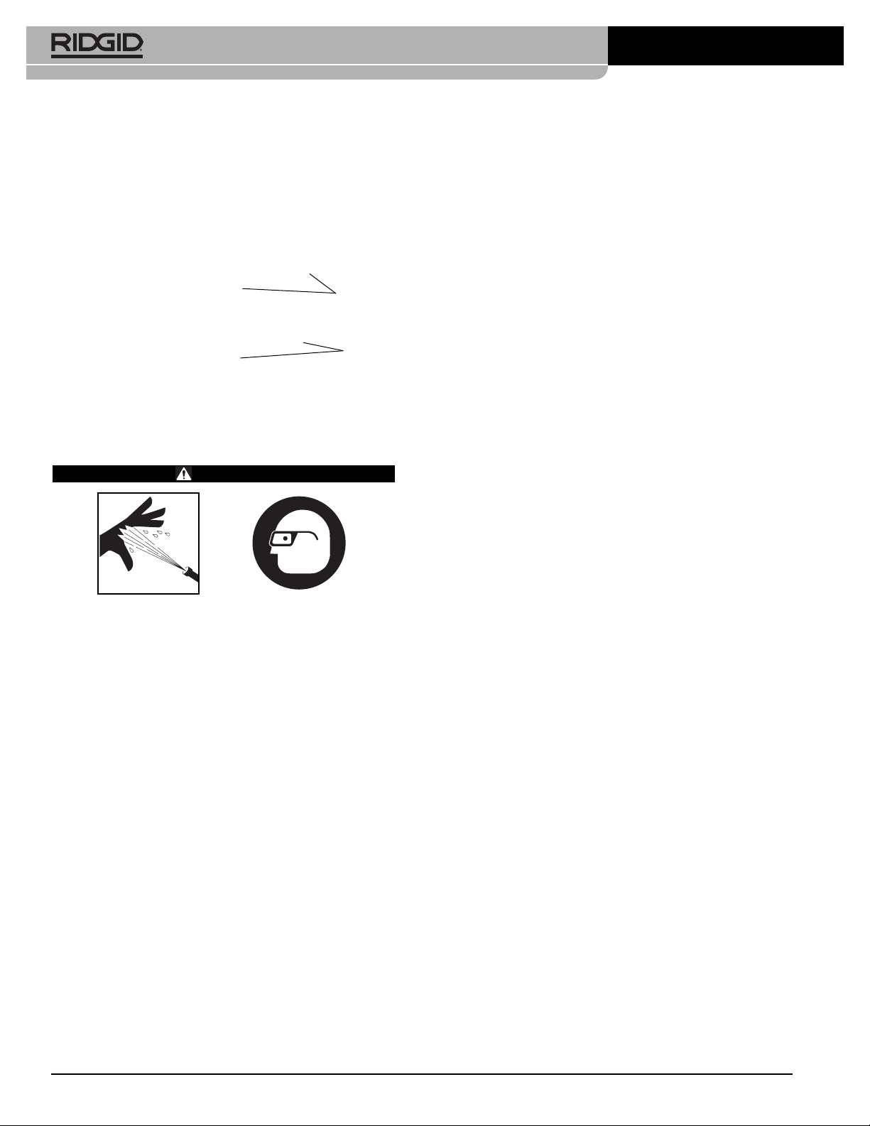
Figure 6A – KJ-2200 Warning Labels
Figure 6B – KJ-2200 Warning Labels
Figure 6C – KJ-3100 Warning Labels
6
Figure 5 – KJ-3100 Handle Assembly
Pre-Operation Inspection
WARNING
Before each use, inspect your water jetter and correct any problems to reduce the risk of serious injury from high pressure water and other causes
and prevent jetter damage.
Always wear safety glasses, gloves and other appropriate protective equipment when inspecting
your jetter to protect against chemicals and bacteria on the equipment.
1. Make sure that the engine switch/key is in the OFF
position.
2. Clean any oil, grease or dirt from the equipment, including the handles and controls. This aids inspection
and helps prevent the machine or control from slipping
from your grip.
3. Inspect the water jetter and accessories for the following:
• Proper assembly and completeness
• Broken, worn, missing, mis-aligned, binding or
loose parts
• Presence and readability of the warning labels.
(See Figure 6)
• Any other condition which may prevent the safe
and normal operation
If any problems are found, do not use the water jetter
until the problems are corrected.
KJ-2200/KJ-3100 Water Jetting Machines
T-Knobs
Insert
Hair Pin
Find Quality Products Online at: [email protected]
www.GlobalTestSupply.com
Page 9
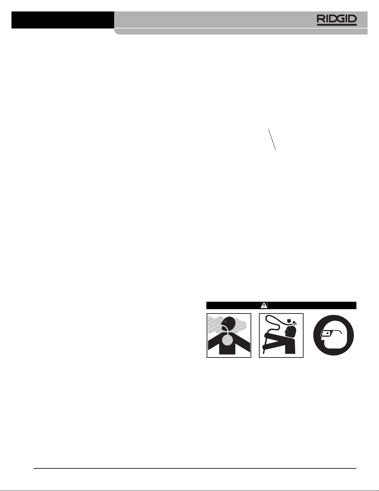
gasoline. See engine operator’s manual for details.
Use caution when handling gasoline. Re-fuel in a
well ventilated area. Do not overfill tank and do not spill
fuel. Make sure tank cap is securely closed.
Figure 8 – KJ-3100 Fuel Tank Access
9. Check the oil level in the pump and gear box (if e quipped) and add oil if needed
(see Maintenance
Instructions section).
Machine and Work Area Set-Up
WARNING
Always wear safety glasses, gloves and other appropriate protective equipment when setting up
your jetter to protect against chemicals and bacteria on the equipment. Rubber soled, non-slip shoes
can help prevent slipping on wet surfaces.
Engines produce carbon monoxide, a colorless, o dor less poison gas. Breathing carbon monoxide can
cause nausea, fainting or death. Do not start and run
engine in an enclosed area, even if doors and windows are open. Only operate outside.
Set up the jetter and work area according to these
procedures to reduce the risk of injury from high
pressure water, chemical burns, infections, carbon
monoxide and other causes, and prevent jetter damage.
7
Figure 6D – KJ-3100 Warning Labels
4. Clean water inlet filter/filter washer.Unscrew cover
from bottom of inlet filter for cleaning. Dirt and debris
can restrict the water flow to the pump and cause performance issues.
Figure 7 – Inlet Filter/Filter Washer
5. Inspect the jetter nozzle orifices for any damage or
blockage. Blockages can be cleaned with a nozzle
cleaning tool. Use care not to enlarge nozzle orifices
while cleaning. Damaged nozzles or nozzles with
enlarged orifices can decrease jetter performance
and should be replaced.
6. Inspect the hoses, connectors and fittings for wear and
damage. If there are any kinks, cracks, breaks or
wear through the outer jacket of the hose or other
damage, do not use the hose. Damaged hoses can
burst or leak high pressure water and cause serious
injury. Replacement hoses and fitting should be rated
at or higher than the jetter pressure.
7. Inspect and maintain the engine per the engine operator’s manual.
8. Check engine fuel level. For the KJ-3100, disconnect the hose reel latch and rotate the hose reel forward until it rests on the frame to provide access to the
engine gas cap
Figure 8
. If needed, add unleaded
KJ-2200/KJ-3100 Water Jetting Machines
Filter
Fuel Tank
Cap
Find Quality Products Online at: [email protected]
www.GlobalTestSupply.com
Page 10
8
1. Check work area for:
• Adequate lighting.
• Flammable liquids, vapors or dust that may ignite. If
present, do not work in area until sources have
been identified and corrected. The jetter is not explosion proof and can cause sparks.
• Clear, level, stable dry place for machine and operator. If needed, remove the water from the work
area. Wood or other coverings may need to be put
down.
• Jetter location that is in a well ventilated outdoor
area. Do not place the jetter indoors, even with
doors and windows open. Jetter can be located remotely from the point of use.
• Suitable water supply.
• Clear path to transport the jetter to the set up location.
2. Inspect the drain to be cleaned. If possible, determine
the access point(s) to the drain, the size(s) and
length(s) of the drain, distance to tanks or mainlines,
the nature of the blockage, presence of drain cleaning
chemicals or other chemicals, etc. If chemicals are
present in the drain, it is important to understand the
specific safety measures required to work around
those chemicals. Contact the chemical manufacturer
for required information.
If needed, remove fixture (water closet, etc.) to allow ac-
cess to the drain. Do not feed the hose through a fixture. This could damage the hose and the fixture.
3. Determine the correct equipment for the application.
See the
Specifications
section for information on these
jetters. Drain cleaners and jetters for other applications
can be found by consulting the RIDGID Catalog, on
4. Make sure all equipment has been properly inspected.
5. Evaluate the work area and determine if any barriers
are needed to keep bystanders away. Bystanders
can distract the operator. If working near traffic,
erect cones or other barriers to alert drivers.
6. If needed, place protective covers in the work area.
The drain cleaning process can be messy.
7. Take the jetter to the well-ventilated outdoor work
area along the clear path. If the machine needs to be
lifted, use proper lifting techniques. Use care moving
equipment up and down stairs, and be aware of possible slip hazards. Wear appropriate footwear to help
prevent slips.
Water Supply
Confirm that there is sufficient water flow for jetter. Run a
hose from the water source to the jetter. Use the largest diameter, shortest length hose possible. A
3
/4" I.D. hose is the
minimum recommended size. An appropriate backflow
prevention device should be used to comply with all local
codes and ordinances. Turn the water on at the source and
measure the time it takes to fill a clean five gallon bucket.
See the following table for maximum bucket fill times for
each jetter.
Insufficient water flow will prevent the jetter from reaching
the pressure rating and could damage the pump. Inspect
the water in the bucket for dirt and debris. Dirt and debris in
the water supply can cause excess pump wear, clog the jetter filters nozzles and reduce performance. Do not use
water from ponds, lakes or other sources that may be
contaminated.
In cases of insufficient water flow, possible solutions include
using fittings to allow multiple supply hoses to be connected to the jetter or the use of a tank.
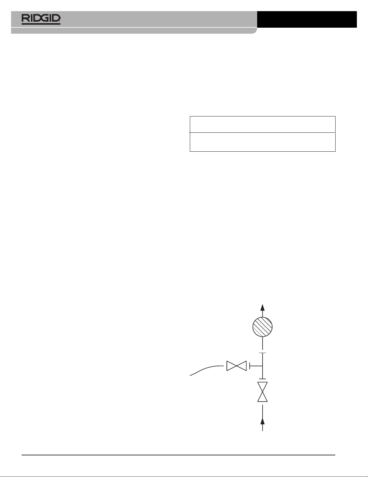
If a tank is used, plumb a tee with full port valves to the jetter water inlet as shown in
Figure 9.
Connect a 3/4" (19 mm)
hose no longer than 6 feet (1.8 m) to the valve on the outlet of the tee, and connect the water supply to the run of the
tee. Either place the hose end in the tank or connect to the
tank outlet. The entire length of the tank hose should be no
more than 5" (12.7 cm) above the jetter water inlet, or
the jetter will not draw water from the tank.
Figure 9 – Water Supply Connections When Using A Tank
KJ-2200/KJ-3100 Water Jetting Machines
Jetter GPM Rating Maximum 5 Gallon
Bucket Fill Time
KJ-2200 2.4 125 seconds
KJ-3100 5.5 55 seconds
Hose To
Tank
Water In To Jetter
Water Supply In
Tee
Inlet Filter
Full Port Valve
Find Quality Products Online at: [email protected]
www.GlobalTestSupply.com
Page 11

9
Fill the tank prior to starting the jetter. When starting jetter,
turn the tank valve OFF. As soon as the jetter is started,
open the tank valve. Monitor the tank water level, and if
needed, stop jetting to allow the tank to refill. Do not allow
the water level to fall below the hose end.
Hot water can be used for improved cleaning. Do not
use water hotter than 140°F. – this can cause the pump
thermal overload to open. When using hot water, use
appropriate personal protective equipment to reduce the
risk of burns.
When using in cold weather, use precautions to prevent
water from freezing in the pump. This can damage the
pump.
Make sure that the inlet supply valve on the jetter is
closed and attach the supply hose to the jetter.
Drain Preparation
If working through a manhole, storm grate or other large access, use pipe and fittings to create a guide for the jetter
hose from the drain opening to operation point. This will prevent the jetter hose from whipping around in the access and
protect the hose from damage.
Figure 10 – Extending the Drain Opening to the
Operation Point
Hose Set-Up
Use care when routing jetter hoses. Routing hoses over
rough surfaces, sharp edges, crossing hoses, etc. can
damage the hose jacket, especially when the jetter is used
in the pulse mode. Keeping the jetter hose on the reel
will help to minimize hose damage.
KJ-2200/KJ-3100 Water Jetting Machines
1. Select a jetter hose size appropriate for the drain
being cleaned. It is not generally recommended to
connect two jetter hoses together for cleaning drains.
The connection between the two hoses is less flexible
and can prevent passage through fittings
See Jetter
Hose Selection Chart.
2. As needed, separate the hose reel from the mot or/pump assembly. Locate the hose reel within 3 feet
of the drain opening. Do not allow excessive amounts
of hose outside of the drain to prevent hose damage. If the hose reel cannot be placed within 3 feet of
the drain opening, extend the drain opening back to
the hose reel with similar sized pipe and fittings.
3. Route a hose from the jetter to the IN fitting on the foot
valve. Use PTFE tape to seal the connection. Position
the foot valve for accessibility. You must be able to
control the jetter hose and the foot valve.
4. Connect the hose from the reel to the OUT fitting
on the foot valve.
Figure 11 – Foot Valve Connection
5. Mark the jetter hose near the end to indicate when the
nozzle is getting close to the drain opening when
withdrawn. This will help prevent the nozzle from
coming out of the drain and whipping around. The distance depends on the configuration of the drain, but
should be at least 4'/1.2 m.
6. Remove the nozzle from the end of the jetter hose
and place the end of the jetter hose in the drain.
Open the inlet supply valve to purge the air and any
debris from the jetter and hoses. Allow water to flow
for at least 2 minutes.
7. Close the inlet supply valve.
8. Select a nozzle. Use nozzles specifically sized for the
jetter being used. Using incorrect nozzles can cause
poor performance (low operating pressure or low
flow) or may damage the jetter with excessively high
In Fitting
Out Fitting
Find Quality Products Online at: [email protected]
www.GlobalTestSupply.com
Page 12
10
KJ-2200/KJ-3100 Water Jetting Machines
pressures. Make sure the nozzle orifices are clear and
open.
See Jetter Nozzle Selection Chart.
If using the RR3000 nozzle for drains larger than 6"
and up to 9"/ 229 mm, the extension must be used.
For drains 6"/ 152 mm and smaller, no extension is
needed. If needed, firmly hand tighten the extension
to the RR3000 – do not over tighten. Using the
RR3000 nozzle in a line larger than 6" and up to 9"
without an extension, or in lines larger than 9" may
allow the nozzle to change direction in the drain, exit
at the user and cause serious injury
(Figure 12)
.
9. Firmly hand tighten the nozzle to the end of the hose
– do not over tighten. Over tightening the nozzle can
damage the nozzle and cause poor performance.
10. Insert the hose with nozzle attached into the drain and
open the inlet supply valve. Confirm that water flows
freely through the nozzle and close the inlet supply
valve.
Figure 12 – RR3000 Nozzle with Extension
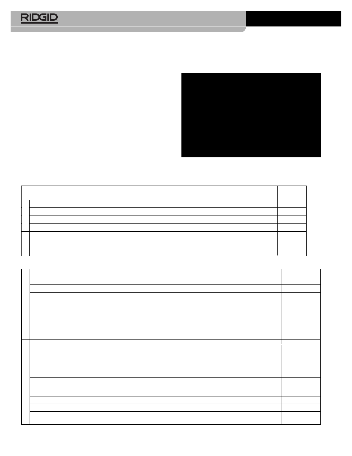
JETTER HOSE SELECTION CHART
Nozzle Hose Hose
Applications Pipe Size Size Size (ID) Size (OD)
Bathroom sinks, urinals, and small lines. 11/4"– 2"
1
/8" NPT
1
/8"
3
/16"
Kitchen sinks, laundry tubs and stacks, clean-outs, and vents. 2" – 3"
1
/8" NPT
3
/16"
1
/4"
Shower and floor drains, lateral lines, and grease traps. 3" – 4"
1
/4" NPT
1
/4"
1
/2"
Lateral and main lines. 4" – 6"
1
/4" NPT
1
/4"
1
/2"
Stacks, clean-outs and vents. 2" – 3"
1
/8" NPT
3
/16"
1
/4"
Floor drains, lateral lines, and grease traps. 3" – 4"
1
/4" NPT
3
/8"
5
/8"
Lateral and main lines. 4" – 10"
1
/4" NPT
3
/8"
5
/8"
Thread Size
Hose Size (Inside Diameter)
Hose Size (Outside Diameter)
Features four (4) reverse jet thrusts for maximum propulsion to jet long distances. Use this
nozzle for most applications.
Uses three jet thrusters in reverse plus one jet pointed forward to penetrate solid grease or sludge
blockages. The forward jet blasts a small hole in the blockage for the nozzle to follow. It is also
very effective when jetting ice blockages.
Use the drop head to help negotiate difficult bends. This nozzle has four (4) reverse jet thrusts.
Use the spinning nozzle to help clean grease and similar blockage from drain.
Use to clear roots and other type of blockages.
NOTE! Use extension to stabilize the RR3000 when cleaning 8" diameter drains.
1
/8" NPT
3
/16"
1
/4"
H-101
H-102
H-104
H-105
1
/4" NPT
3
/8"
5
/8"
H-111
H-112
H-115
RR3000
Thread Size
Hose Size (Inside Diameter)
Hose Size (Outside Diameter)
Features three reverse jet thrusts for maximum propulsion to jet long distances. Use this nozzle for most applications.
Uses three jet thrusters in reverse plus one jet pointed forward to penetrate solid grease or sludge
blockages. The forward jet blasts a small hole in the blockage for the nozzle to follow. It is also
very effective when jetting ice blockages.
Use the drop head to help negotiate difficult bends. This nozzle has three reverse jet thrusts.
Use the spinning nozzle to clean grease and similar blockage from drain.
1
/8" NPT
1
/8"& 3/16"
3
/16"& 1/4"
H-61
H-62
H-64
H-65
1
/4" NPT
1
/4"
1
/2"
H-71
H-72
H-75
JETTER NOZZLE SELECTION CHART
KJ-3100
KJ-2200
KJ-2200
Extension
KJ-3100
Find Quality Products Online at: [email protected]
www.GlobalTestSupply.com
Page 13
11
KJ-2200/KJ-3100 Water Jetting Machines
Operating Instructions
WARNING
Always wear eye protection to protect your eyes
against dirt and other foreign objects. Always wear
appropriate personal protective equipment for the
work environment.
Never operate the jetter with the hose end outside of
the drain. Hose can whip, causing striking injuries
and spray can penetrate skin and cause serious injury.
High pressure fluid can inject under skin resulting in
serious injury, including amputation. Do not direct
spray at people or animals.
Do not operate jetter above pressure rating or 140°F
(inlet water temperature). This increases the risk of
injury, including burns, and damage to the jetter.
One person must control both the jetting process
and the foot valve. Always use the foot valve. If
the jetter hose comes out of the drain, the operator
must be able to shut the water flow off to reduce the
risk of the jetter hose whipping, causing striking
and high pressure injection injuries.
Always use appropriate personal protective equipment while handling and using drain cleaning equipment. Drain may contain chemicals, bacteria and
other substances that may be toxic, infectious,
cause burns or other issues. Appropriate personal
protective equipment always includes safety glasses
and gloves, and may also include equipment such as
latex or rubber gloves, face shields, goggles, protective clothing, respirators, and steel toed footwear.
Follow operating instructions to reduce the risk of
injury from whipping hoses, high pressure liquid injection, carbon monoxide and other causes.
1. Make sure that machine and work area is properly set
up and that the work area is free of bystanders and
other distractions. If the jetter is located remotely
from the point of use, another person should be located at the jetter.
2. Insert the hose with nozzle attached into the drain at
least three feet so that the end of the hose will not
come out of the drain and whip around when the
machine is started.
3. Confirm that the pulse actuator lever is rotated count er-clockwise in the “Pressure” position
(Figure 16)
.
4. Open the inlet supply valve. Never start the engine
without the water supply turned ON. This can damage
the pump.
5. Press the foot valve to reduce pressure and allow the
engine to start. Confirm that water flows freely through
the nozzle. Following the starting instructions supplied
in the engine manual, start the engine. Allow the engine to warm up.
Figure 13 – Controls
6. Turn the unloader valve while monitoring the pressure
gauge to adjust the pressure as desired (clockwise to
increase pressure, counter-clockwise to decrease
pressure). Do not exceed the machine pressure rating being used. Do not force the unloader valve or use
wrench es or tools to turn. This will damage the unloader valve.
If the jetter will not generate the rated pressure or is er-
ratic
• Make sure the engine throttle is properly adjusted.
• Make sure that the inlet supply valve is fully open
and other valves in the supply system are fully
open.
• Turn unloader valve clockwise to increase pres-
sure. Do not force.
• Make sure the pulse actuator is on the “Pressure”
setting.
• Cycle the pulse actuator between the “Pressure”
and “Pulse” position several times while the unit is
running to clear any trapped air from the system.
Pressure Gauge
Unloader
Valve
Pulse Actuator
Thermal
Overload
Jetter Pressure Rating
KJ-2200 2200 psi
KJ-3100 3000 psi
Find Quality Products Online at: [email protected]
www.GlobalTestSupply.com
Page 14
12
KJ-2200/KJ-3100 Water Jetting Machines
• Inspect system for leaks. Use caution during inspection to prevent injury. If leaks are found, shut
jetter OFF before fixing.
• Turn the jetter OFF. Check the inlet filter/filter
washer and make sure that they clear of debris.
• Make sure there is adequate water flow to the
jetter.
• Turn the jetter and inlet supply valve OFF. Re move the nozzle and clean the orifices with the
nozzle cleaning tool.
• Run the jetter without a nozzle on the hose to remove air or debris from the system. Turn the jetter
OFF before removing or attaching the nozzle.
7. Assume a proper operating position.
• Be sure you can control the ON/OFF action of
the foot valve. Do not press the foot valve yet.
• Be sure that you have good balance and do not
have to overreach.
• You must be able to place one hand on the jetter
hose at all times to control and support the hose.
• You must be able to reach the reel for coiling the
hose.
This operating position will help to maintain control
of the jetter hose.
Figure 14 – Proper Operating Position
Jetting the Drain
When jetting a drain, typically the hose is fed into the
drain the full distance to be cleaned and slowly pulled
back. This allows the high pressure water directed at the
drain walls to remove build-up.
Release the locking pin on the hose reel. With at least
three feet of hose in the drain and one hand on the hose
to control its movement, depress the foot valve. The reverse jet thrusters on the nozzle will help pull the hose into
the drain. Feed the hose in the as far as needs to be
cleaned. If the hose stops, it has encountered some type
of obstruction.
If the nozzle cannot pass through an obstruction, such as
a change in direction (trap, turn, etc.) or a blockage.
• Use sharp thrusts of the hose
• Rotate the hose a quarter to half turn to orient the
set of the hose to the direction change (If the
hose is rotated, once through the obstruction,
turn the hose back to help prevent kinks)
See
Figure 15.
• Use the pulse mode.
(see next section)
• Use a trap hose or smaller diameter hose.
Figure 15 – Rotating the Hose.
Once past a blockage, take the time to clean that section
of drain prior to moving forward. Move several feet past
the area of the obstruction and slowly pull the nozzle
back through the area of the obstruction. Do this several
times and then move further into the drain.
Find Quality Products Online at: [email protected]
www.GlobalTestSupply.com
Page 15
13
KJ-2200/KJ-3100 Water Jetting Machines
Watch the drain water level. If the water level gets too
high, you may need to turn the jetter OFF and allow the
water to drain prior to continuing. Jetting when the line is
full of water is less effective than when the line is empty.
Do not allow the jetter to run for extended period of time
with the foot valve OFF. When the foot valve is OFF,
water recirculates in the pump and cause the water to heat
up. This can cause the pump thermal overload to open.
Once the nozzle is the desired distance into the drain,
slowly (1 ft /minute for heavy drain accumulations) pull the
nozzle back through the drain. Use one hand to control the
hose and the other to wind the hose onto the reel. Watch
as the nozzle gets closer to the drain opening that the nozzle does not come out of the drain while water is flowing.
This could allow the hose to whip around and cause
striking and high pressure fluid injuries. Always control the
hose. Look for the mark on the hose near the nozzle.
Release the foot valve to shut off the water flow.
Turn OFF the engine as directed in the engine manual,
and depress the foot valve to release the system pressure.
Never leave the system pressurized. If needed, change
the nozzle and continue cleaning following the above
process. Several passes through a line are recommended
for complete cleaning.
When finished, with the jetter shut off, remove the nozzle
and open inlet supply valve to flush out the pump and
hose. If using the jetter in cold weather conditions, immediately drain the water from the system to help prevent
damage from freezing. See
Machine Storage
for infor-
mation on freeze protecting.
Using the Pulse Mode
When manipulating the hose is not enough to pass through
a direction change or obstruction, the pulse mode should
be used. The pulse mode induces large variation in water
pressure that causes the hose to vibrate, easing hose
advancement.
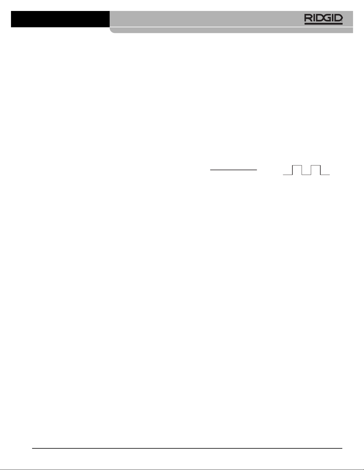
1. Turn the pulse actuator lever clockwise to the “Pulse”
position. In pulse mode, the pressure gauge will read
less than full pressure. This is normal.
Figure 16 – Pulse Actuator Lever Position
2. If needed, use sharp thrusts of the hose and hose rotation to help the nozzle through the obstruction.
3. Once through the obstruction, turn the pulse actuator
lever counter-clockwise to the “Pressure” position.
Do not leave the jetter in pulse mode any longer
than needed to pass through an obstruction. Exces sive use of the pulse feature can cause premature
wear on hoses and system.
Using Water Jetter Machine as a
Pressure Washer
The RIDGID water jetting machines can also be used as
pressure washers with the addition of the pressure wash
package. Use as a pressure washer is similar to use as a
jetter, and those instructions should be used in conjunction
with the following.
1. Locate an appropriate work area.
2. Make sure all equipment has been properly inspected.
3. Attach the wash wand to the wash wand hose. Al ways use hose with a pressure rating at least as
high as the jetter pressure rating. Use a thread sealant
to prevent leaks.
4. Attach hose to the jetter outlet. Make sure the ends of
the hose are securely connected to prevent them
from coming off under pressure.
5. Connect an appropriate water supply, as discussed
earlier, to the jetter.
6. Open the inlet supply valve and squeeze the wash
wand trigger to allow water to flow and purge any air
from the system. Never start the engine without the
water supply turned ON. This can damage the pump.
PULSEPRESSURE
Find Quality Products Online at: [email protected]
www.GlobalTestSupply.com
Page 16
14
KJ-2200/KJ-3100 Water Jetting Machines
7. Make sure that pulse actuator lever is rotated counterclockwise in the “Pressure” position.
8. Wash Wand Nozzle Adjustments – By rotating the
nozzle, the wash pattern can be adjusted from a fine
stream to a wide fan type spray. By pulling the nozzle
forward (low pressure) and backward (high pressure), the pressure can be adjusted. Make sure that
the nozzle is pulled back to the high pressure position
to start operation.
Figure 17 – Wash Wand Nozzle Adjustments
9. Wash Wand Lock Out – the wash wand includes a
lock out on the back of the trigger. Flip the lock out
down to prevent the operation of the trigger when the
wash wand is not in use.
10. With the wand pointed in a safe direction, squeeze the
wash wand trigger to reduce pressure and allow the
engine to be started. Following the starting instructions
supplied in the engine manual, start the engine. Allow
the engine to warm up. Release the trigger as soon as
the engine starts.
11. With the wand pointed in a safe direction, squeeze the
wash wand trigger. Turn the unloader valve while
monitoring the pressure gauge to adjust the pressure as desired. Do not exceed the machine pressure
rating. Release the wash wand trigger.
Pressure Washer Operation
1. When using as a pressure washer use both hands to
grip and direct the wash wand for greater control.
Never direct the wash wand at people. High pressure
fluid can inject under skin resulting in serious injury.
Never direct wash wand at electrical equipment or
wiring to reduce the risk of electrical shock.
2. Control the flow of water with the trigger. Use care
when using the pressure washer. Holding the nozzle
too close to a surface can damage it. Test a small, inconspicuous area to confirm the settings work as
desired.
3. Do not allow the jetter to run for extended period of
time with the trigger OFF. When the trigger is OFF,
water recirculates in the pump and it causes the
water to heat up. This can cause the pump thermal
overload to open.
4. Once pressure washing is complete, release the trigger and turn OFF the engine as directed in the engine
manual. Squeeze the trigger to release system pressure. Never leave the system pressurized.
Detergent Injector
1. If needed, attach the detergent injector to the outlet
port. Remove the output hose and attach the detergent injector with arrow on the unit pointing the same
direction as the water flow. Use thread sealant to
prevent leaks. Reattach the output hose.
2. Attach the siphon hose to the detergent injector.
Place the strainer end of hose into the detergent
container. Only use detergents designed for use with
pressure washers. Follow all detergent instructions.
Do not spray flammable liquids or toxic chemicals.
Other detergents, solvents, cleaners, etc. can damage
the jetter, or cause serious injury.
3. When pressure washing, detergents are only dispensed when wash wand nozzle is in the low pressure position. Pull the nozzle forward to the low
pressure position to dispense detergent.
4. During operation, the detergent application rate can be
adjusted by turning the sleeve on the detergent injector. Counter-clockwise increases the amount of
detergent, clockwise decreases.
5. When detergent application is complete, remove the
strainer from the detergent, place into a bucket of
clean water and flush the system of any detergent.
Maintenance Instructions
WARNING
Before performing any maintenance, engine switch
should be in OFF position and spark plug wires
should be disconnected to prevent inadvertent operation. Press foot valve or wand trigger to release
any fluid pressure in system.
Always wear safety glasses and gloves when performing any maintenance to help protect against
drain chemicals and bacteria.
Cleaning
The hose should be cleaned as needed with hot, soapy
water and/or disinfectants. Do not allow water to enter
the engine or electrical system. Do not clean with pressure washer. Wipe the unit down with a damp cloth.
Low
Pressure
High
Pressure
Lock Out
Pattern
Adjustment
Find Quality Products Online at: [email protected]
www.GlobalTestSupply.com
Page 17
15
KJ-2200/KJ-3100 Water Jetting Machines
Engine
Maintain the engine as directed in the engine operator’s
manual supplied with the unit.
Pump Lubrication
Check the pump oil level prior to use. Place the jetter on
a level surface. Wipe any dirt and debris from the area
of the dipstick and remove the dipstick – check the oil
level. If needed, add SAE 30W non-detergent oil. Do not
overfill. Reinstall dipstick.
Change oil in pump after first 50 hours of operation
and every 500 hours of operation after that. With the
pump warm from operation, remove plug on bottom of
pump and drain oil into suitable container. Replace
plug. Fill with approximately 32 oz of SAE 30W non-detergent oil using the checking procedure.
Gearbox Lubrication
Check the gearbox oil level prior to use. Place the jetter
on a level surface. Wipe any dirt and debris from the
area of the dipstick and remove the dipstick – check the
oil level. If needed, add SAE 90W gear lubricant. Do not
overfill. Reinstall dipstick.
Change oil in gearbox every 500 hours of operation.
With the gearbox warm from operation, remove plug on
bottom of gearbox and drain oil into suitable container.
Replace plug. Fill with approximately 8 oz of SAE 90W
gear lubricant oil using the checking procedure.
Preparing Pump for Cold Weather
Storage
If the jetter will be stored under conditions
where the temperature is near or below 32°F (0°C),
the jetter must be properly prepared. If water freezes in
the pump, it can damage it.
There are two methods for preparing the jetter for cold
weather storage. The first is to open all valves in the system and use compressed air to force any water out of
the system. This can also be used to remove water
from the hoses.
The second method uses RV antifreeze (non-ethylene
glycol antifreeze). Do not use ethylene glycol antifreeze
in the jetter pump. Ethylene glycol cannot be used in
drainage systems.
1. Attach a 3 foot section of hose to the inlet supply
valve and open valve.
2. Place the end of the hose into the container of RV antifreeze.
3. Remove the nozzle from the end of the hose.
4. Start the jetter and run until antifreeze comes out of
the end of the hose.
Accessories
WARNING
To reduce the risk of serious injury, only use accessories specifically designed and recommended
for use with the RIDGID Water Jetter Machines,
such as those listed below. Other accessories suitable for use with other tools may be hazardous
when used with RIDGID Water Jetter Machines.
NOTICE
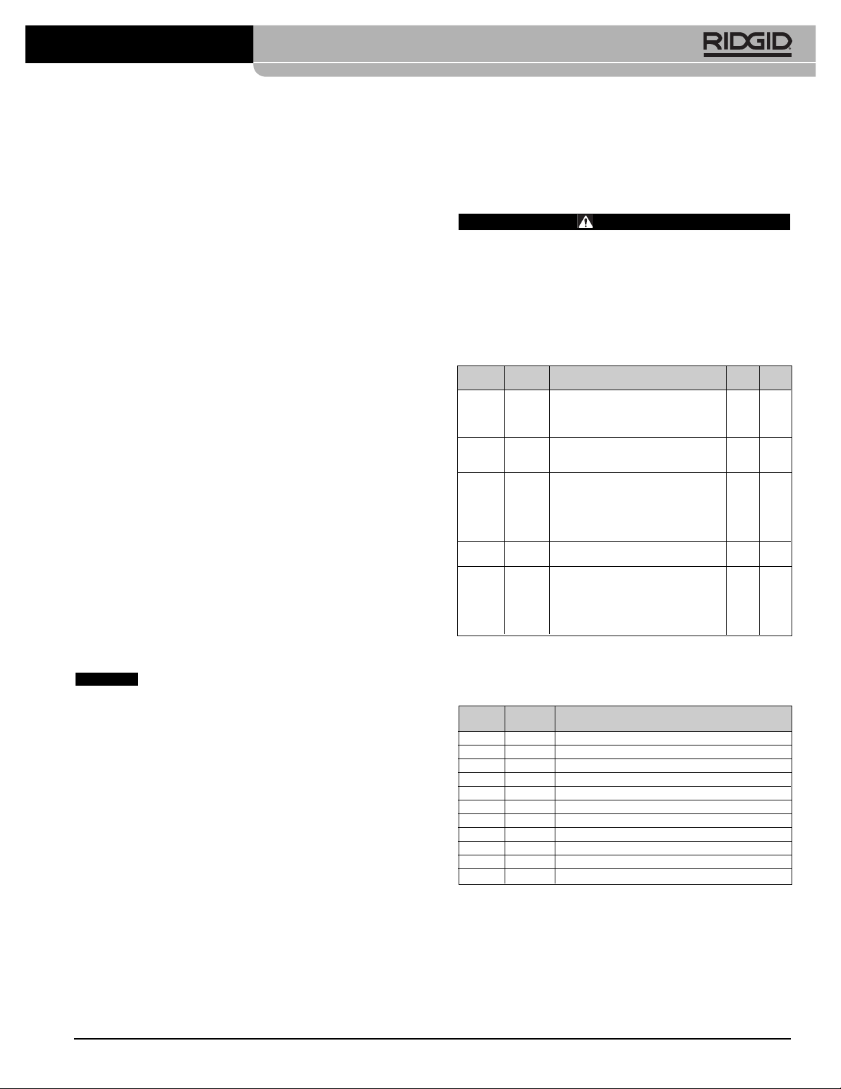
Catalog Model
No. No. Description
62882 H-5 Mini Hose Reel (No Hose included)
64737 H-30 H-30 Cart with Hose Reel
62877 H-30 WH H-30 Cart with Hose Reel and 110' x
1
/2" Jet Hose
64077 HP-22 Pressure Wash Package, KJ-2200
64767 HW-22 Wash Wand, KJ-2200
51572 H-1235 Wash Wand Hose
1
/2" x 35'
48157 FV-1 Foot Valve
66732 HF-4 Quick Connect Hose
48367 H-25 Winterizing Kit
47542 H-21 Nozzle Cleaning Tool
67187 H-32 Jet Vac
KJ-2200 Jetter Accessories
Catalog Model Hose Hose
No. No. Description I.D. O.D.
64772 H-61 Propulsion Nozzle
1
/8" NPT
64777 H-62 Penetrating Nozzle Fits
1
/4" Hose
64782 H-64 Drop Head Nozzle
82842 H-65 Spin Nozzle 2200
64787 H-71 Propulsion Nozzle
1
/4" NPT
64792 H-72 Penetrating Nozzle Fits
1
/2" Hose
82852 H-75 Spin Nozzle 2200
47592 H-1425
1
/4" x 25'
3
/16"1/4"
47597 H-1435
1
/4" x 35'
3
/16"1/4"
47602 H-1450
1
/4" x 50'
1
/4" Trap Hose3/16"1/4"
49272 H-1475
1
/4" x 75' Orange
3
/16"1/4"
49277 H-1400
1
/4" x 100'
3
/16"1/4"
64732 H-1415
1
/4" x 150'
3
/16"1/4"
50002 HL-1 Flexible Leader,
1
/4″
1
/8"3/16"
50007 HL-2 Flexible Leader,
1
/2″
1
/8"3/16"
47607 H-1250
1
/2" x 50'
1
/4"1/2"
47612 H-1275
1
/2" x 75'
1
/4"1/2"
47617 H-1200
1
/2" x 100'
1
/4"1/2"
51587 H-1211
1
/2" x 110'
1
/2" Jet Hose
1
/4"1/2"
49487 H-1215
1
/2" x 150' Black
1
/4"1/2"
51597 H-1220
1
/2" x 200'
1
/4"1/2"
KJ-2200 Jetter Nozzles and Hoses
Find Quality Products Online at: [email protected]
www.GlobalTestSupply.com
Page 18
16
KJ-2200/KJ-3100 Water Jetting Machines
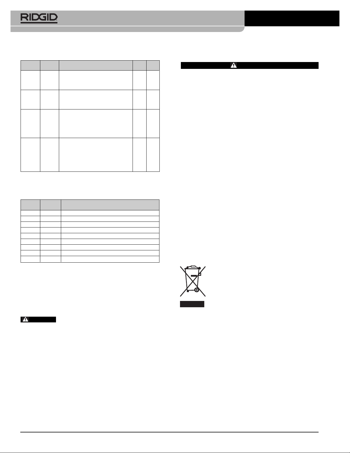
Catalog Model
No. No. Description
62882 H-5 Mini Hose Reel
64862 H-38 Hose Reel (Fits KJ-3100)
64902 H-38 WH Hose Reel with 200' x
3
/8" ID Hose (Fits KJ-3100)
64797 HW-30 Wash Wand, KJ-3100
48367 H-25 Winterizing Kit
48157 FV-1 Foot Valve
66732 HF-4 Quick Connect Hose (Reel to Foot Valve)
47542 H-21 Nozzle Cleaning Tool
67187 H-32 Jet Vac
KJ-3100 Jetter Accessories
Catalog Model Hose Hose
No. No. Description I.D. O.D.
38698 H-101 Propulsion Nozzle
1
/8" NPT
38713 H-102 Penetrating Nozzle Fits
1
/4" Hose
38703 H-104 Drop Head Nozzle
38723 H-105
1
/8" NPT Spin Nozzle
38693 H-111 Propulsion Nozzle
1
/4" NPT
38708 H-112 Penetrating Nozzle Fits
3
/8" Hose
38718 H-115S
1
/4" NPT Spin Nozzle
16713 RR3000 Root Ranger Nozzle
47592 H-1425
1
/4" x 25' Trap Hose
3
/16"1/4"
47597 H-1435
1
/4" x 35' Trap Hose
1
/4" Trap Hose3/16"1/4"
47602 H-1450
1
/4" x 50' Trap Hose Orange
3
/16"1/4"
49272 H-1475
1
/4" x 75' Trap Hose
3
/16"1/4"
49277 H-1400
1
/4" x 100' Trap Hose
3
/16"1/4"
64732 H-1415
1
/4" x 150' Trap Hose
3
/16"1/4"
64827 H-3835
3
/8" ID x 35' Wash Hose
3
/8"5/8"
64832 H-3850
3
/8" ID x 50' Jet/Wash Hose
3
/8"5/8"
64837 H-3810
3
/8" ID x 100' Jet Hose3/8" Jet Hose3/8"5/8"
64842 H-3815
3
/8" ID x 150' Jet Hose Black
3
/8"5/8"
64847 H-3820
3
/8" ID x 200' Jet Hose
3
/8"5/8"
64852 H-3825
3
/8" ID x 250' Jet Hose
3
/8"5/8"
64857 H-3830
3
/8" ID x 300' Jet Hose
3
/8"5/8"
KJ-3100 Jetter Nozzles and Hoses
Machine Storage
Store the jetter in a well ventilated area
protected from rain and snow. Keep the machine in a
locked area that is out of reach of children and people unfamiliar with jetters. This machine can cause serious injury
in the hands of untrained users.
See Maintenance section
for information on cold weather storage. See engine operator’s manual for specific information on engine storage.
Service And Repair
WARNING
Improper service or repair can make machine unsafe to operate.
Disposal
Parts of the water jetter contain valuable materials and can
be recycled. There are companies that specialize in recycling that may be found locally. Dispose of the com ponents in compliance with all applicable regulations.
Contact your local waste management authority for more
information.
For EC Countries: Do not dispose of electrical equipment with household waste!
According to the European Guideline 2002/ 96/ EC for Waste Electrical and Electronic
Equipment and its implemen tation into na-
tional legislation, electrical equipment that is
no longer usable must be collected separately and disposed of in an environmentally correct manner.
WARNING
Find Quality Products Online at: [email protected]
www.GlobalTestSupply.com
Page 19
17
KJ-2200/KJ-3100 Water Jetting Machines
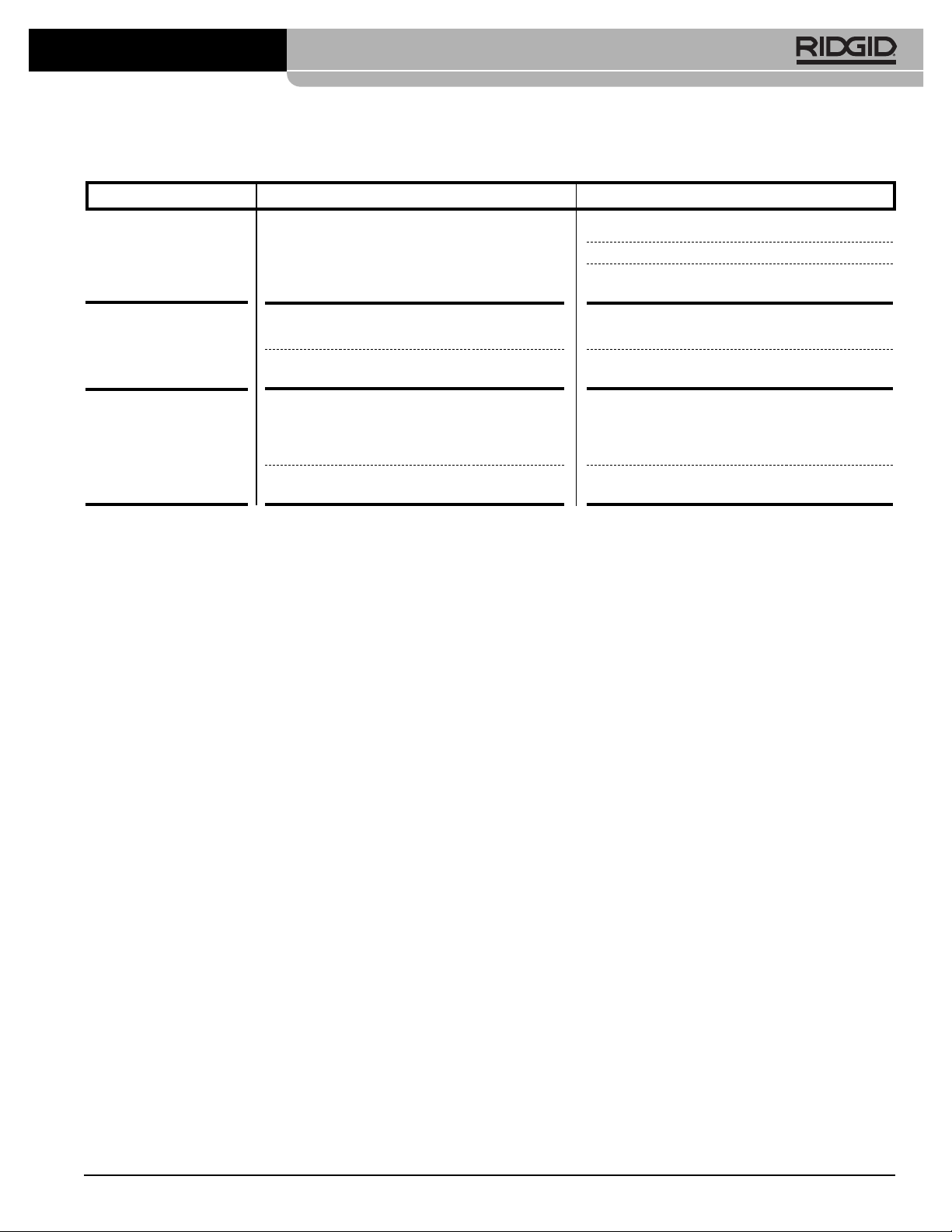
PROBLEM CAUSE CORRECTION
Jetter runs but produces
little or no pressure.
Jetter will not adjust to
full operating pressure
at start-up.
Jetter pressure gage
oscillates from 500 to
full operating pressure.
Troubleshooting
Inadequate water supply.
Air is trapped in system.
Jetter nozzle thrusters are blocked.
Jetter nozzle thrusters are blocked.
Debris or air trapped in system.
Make certain water supply faucet is ON.
Make certain jetter's water supply inlet valve is ON.
Make certain water supply hose is clear and not
kinked or collapsed.
Remove nozzle from jet hose and run jetter to flush
air/debris from system.
Remove nozzle and clean thruster orifices with nozzle cleaning tool.
Remove nozzle. Use nozzle cleaning tool to clear
nozzle orifices: select proper wire size and push
completely through each thruster orifice to remove
debris.
Remove nozzle and insert jet hose in drain line.
Run jetter to flush trapped air or debris.
Find Quality Products Online at: [email protected]
www.GlobalTestSupply.com
 Loading...