


4. Fully open the threading machine chuck and remove pipe.
5. Insert the nipple chuck into the machine chuck. Align the
grooves/flats in nipple chuck body with the machine chuck
inserts. Securely close the machine chuck onto the nipple
chuck.
If using 819 Nipple Chuck with the 535A or 1822 threading
machines, assemble the 839 Adapter kit as per the instructions.
6. If needed, remove the thread adapter with the wrench. Do
not operate the machine with the wrench installed, this
increases the risk of striking or crushing injuries.
Figure 2 – Installing Nipple Chuck and Insert
Figure 3 – Installing Nipple Chuck Adapter and Nipple
7. If needed, install the insert
(Figure 2)
:
•For 1
1
/4" or larger pipe, the insert is not used.
• For 1" pipe, install the insert into the nipple chuck with
the large end out.
•For
3
/4" or smaller pipe, install the insert with the small
end out.
8. Install the proper size pipe adapter and tighten with the
wrench
(Figure 3)
. Remove wrench.
9. Screw the threaded end of the nipple into the pipe adapter
by hand until the pipe end stops against the insert. If this
does not happen, the thread is oversized and may jam in
the adapter.
10. Following the instructions for the threading machine used,
ream and thread the nipple. Watch closely for any interference between parts – if needed, stop the machine by
removing foot from the foot switch.
11. Remove foot from the foot switch and move the threading
machine switch to OFF position.
12. Insert the wrench pin into one of the holes on body of the
nipple chuck. Turn the wrench to release the finished nipple and unscrew from the adapter.
See Figure 4
. Remove
wrench.
819 and 1219 Nipple Chuck
Instructions
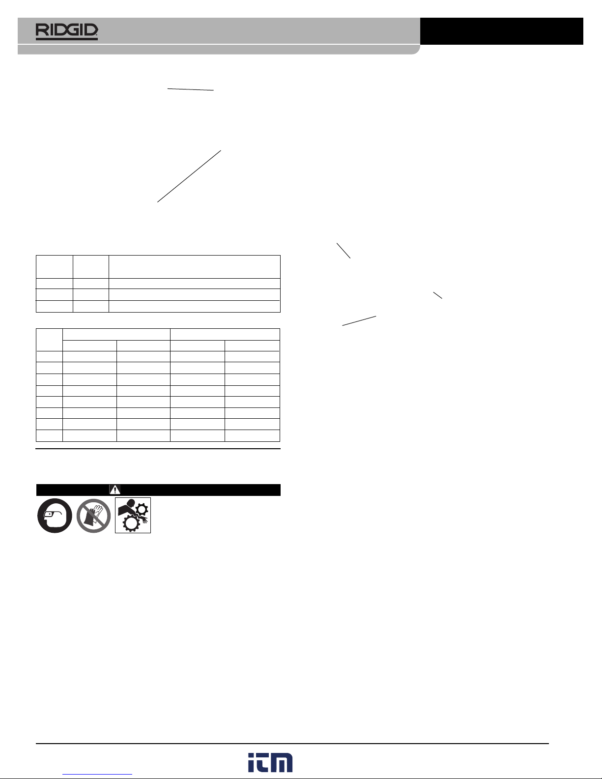
WARNING
Read these instructions and
the warnings and instruc tions for all equipment be ing used before operating
this tool to reduce the risk of serious personal injury.
• Do not wear gloves or loose clothing when operating.
Keep sleeves and jackets buttoned. Clothing can be caught
by the pipe or tool resulting in entanglement.
• Keep hands away from rotating pipe and parts. Allow the
machine to come to a complete stop before touching the
pipe or tool. This reduces the risk of en tanglement, crushing
or striking injuries.
• Remove wrench from Nipple Chuck before turning on
the Threading Machine. This reduces the risk of striking or
crushing injuries.
Description
RIDGID®819 and 1219 Nipple Chucks are designed to hold
short or close NPT nipples for threading.
The Model 819 Nipple Chuck is used with 2" capacity and
larger threading machines, such as the 300 Power Drive, 300
Compact, 535, 1233 and 1224 Threading Machines. With the
839 Adapter kit, the 819 can be used with 535A and 1822
Threading Machines. The Model 1219 is used with 1215
Threading Machine.
The 819 is available in a BSPT configuration.
Figure 1 – 819 Nipple Chuck and Accessories
Inspection/Maintenance
Inspect the Nipple Chuck before each use for proper assembly,
wear, damage or other issues that could affect safe use. Clean
the chuck to aid inspection and improve control.
Lubricate the chuck as needed with a light general purpose lubricating oil. Clean excess oil from exposed surfaces.
Set Up and Operation
1. Make sure all equipment is inspected and set up per its
instructions.
2. Following the instructions for the threading machine, ream
and thread one end of the pipe and cut to the desired
length.
3. Remove foot from the foot switch and move the threading
machine switch to the OFF position. Do not use machine
if the foot switch is broken or missing.
819 and 1219 Nipple Chuck Instruction Sheet
RIDGID
®
4/13
070-147-100.10
REV. A
Printed in U.S.A.
EC39645
Nipple
Chuck
Body
Insert
Wrench
Adapter
Nipple
Wrench
Adapters
Insert
www. .com
information@itm.com1.800.561.8187
2
819 and 1219 Nipple Chuck Instruction Sheet
Figure 4 – Removing Nipple
Accessories
Pipe Adapters
Utilisation des mandrins à raccords
n° 819 et n° 1219
AVERTISEMENT
Afin de limiter les risques
de graves blessures corporelles, familiarisez-vous
avec l’ensemble des consignes de sécurité visant cet appareil et tout autre
dispositif concerner avant d’utiliser l’appareil.
• Ne jamais porter de bijoux ou d’accessoires vestimentaires lors de l’utilisation de l’appareil. Boutonnez vos
manches et vos blousons. L’entraînement des vêtements par
le tuyau ou le mécanisme augmenterait les risques d’en chevêtrement.
• Eloignez vos mains des tuyaux et mécanismes en rota-
tion. Attendez que la machine s’arrête complètement avant
de manipuler le tuyau ou l’outil. Cela limitera les risques
d’enchevêtrement, d’écrasement et autres blessures.
• Remove wrench from Nipple Chuck before turning on
the Threading Machine. This reduces the risk of striking or
crushing injuries.
Description
Les mandrins à raccords RIDGID®n° 819 et n° 1219 assurent
le maintien des raccords NPT courts et manchons NPT lors de
leur filetage.
Le mandrin à raccords n° 819 se monte sur les machines à
fileter d’une capacité d’au moins 2’’ telles que les systèmes
d’entraînement n° 300 et n° 300 Compact, ainsi qu’avec les
machines à fileter type 535, 1233 et 1224. Equipé de
l’adaptateur n° 839, le 819 se monte également sur les
machines à fileter type 535A et 1822. Le modèle 1219 est
prévu pour la machine à fileter type 1215.
Le 819 est également disponible en filetage BSPT.
Figure 1 – Mandrin à raccords n° 819 avec accessoires
Contrôle et entretien de l’outil
Examinez le mandrin à raccords avant chaque utilisation pour
vous assurer de son bon assemblage et pour signes d’usure ou
d’anomalie qui pourraient nuire à son bon fonctionnement et à
sa sécurité. Nettoyez le filetage de l’outil afin d’en faciliter
l’examen et mieux le contrôler.
Au besoin, lubrifiez le mandrin à raccords à l’aide d’une huile
minérale légère, puis éliminez toutes traces d’huile des surfaces
exposées de l’outil.
Montage et utilisation de l’outil
1. Assurez-vous du contrôle et de l’installation de l’ensemble
du matériel utilisé selon les consignes applicables.
2. Alésez et filetez l’extrémité du tuyau selon les consignes
de la machine à fileter utilisée, puis coupez-le à la longueur
voulue.
3. Lâchez la pédale de commande et mettez le commutateur
de la machine à fileter à la position OFF. N’utilisez pas la
machine en l’absence d’une pédale de commande en
bon état de marche.
4. Ouvrez le mandrin de la machine à fileter et retirez le
tuyau.
5. Introduisez le mandrin à raccords dans celui de la ma chine. Alignez les rainures et les plats du mandrin à raccords avec les inserts de celui de la machine. Refer mez le
mandrin de la machine sur le mandrin à raccords.
Lors de l’utilisation du mandrin à raccords n° 819 sur une
machine à fileter type 535A ou 1822, assemblez l’adapta teur n° 839 selon les instructions.
6. Au besoin, enlevez l’adaptateur de filetage à l’aide de la clé
fournie. N’oubliez pas d’enlever la clé avant de mettre la
machine en marche afin de limiter les risques d’accident.
7. Au besoin, installez l’insert
(Figure 2)
de la manière suivante:
• L’insert n’est pas utilisé pour les tuyaux de 11/4" de
diamètre ou plus.
• Pour les tuyaux de 1", introduisez la petite extrémité de
l’insert dans le mandrin.
Wrench
Nipple
Size NPT Standard BSPT Standard
(Inch) Catalog No. Model No. Catalog No. Model No.
1
/
8
51040 E-729 – –
1
⁄
4
51045 E-730 68195 E-730-B
3
⁄
8
51050 E-731 68200 E-731-B
1
⁄
2
51055 E-732 68165 E-732-B
3
⁄
4
51060 E-733 68170 E-733-B
1 51065 E-734 68175 E-734-B
1
1
⁄
4
51070 E-735 68180 E-735-B
1
1
⁄
2
51075 E-736 68185 E-736-B
Catalog Model Description
No. No.
35867 839 Adapter Kit for 535A/1822 Machine
51020 D-380-X Nipple Chuck Wrench
51035 Insert
Clé
Adaptateurs
Insert
www. .com
information@itm.com1.800.561.8187
 Loading...