

Page 1

RICOH ST23
SERVICE MANUAL
Page 2
OVERALL MACHINE INFORMATION 6 March 1992
1. OVERALL MACHINE INFORMATION
1.1 SPECIFICATIONS
Configuration: Console
Number of Bins: 20 + proof tray
Paper for Proof Tray: Size: Maximum: A3, 11" x 17"
Minimum: A5, 51/2" x 81/2" (sideways)
Weight: 52 g/m2 ~ 160 g/m2, 14 ~ 43 lb
Paper for Bins: Sort/Stack Mode:
Size Maximum: A3, 11" x 17"
Minimum: A5, 51/2" x 81/2" (sideways)
Weight 52 g/m2 ~ 160 g/m2, 14 lb ~ 43 lb
Staple Mode:
Size Maximum: A3, 11" x 17"
Minimum: A4, 81/2" x 11"
Weight 64 g/m2 ~ 80 g/m2, 17 lb ~ 21 lb
Stapler Capacity: From 2 to 50 sheets (80 g/m2, 20 lb)
Bin Capacity:
1 sided copies 2 sided copies
Sort mode 70 sheets 50 sheets
Stack mode 50 sheets 35 sheets
(80 g/m
2
, 20 lb)
Proof Tray Capacity: 250 sheets (80 g/m2, 20 lb)
20 sheets (translucent paper)
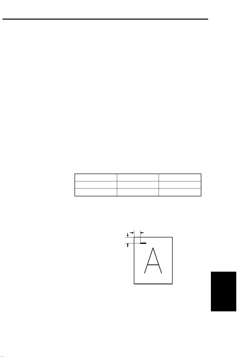
Staple Position: a = b = 5 ± 2 mm
b
a
Staple Time: Within 1.5 seconds/staple
Staple Replenishment: Cartridge exchange (5,000 pieces/cartridge)
Power Source: 1st sorter: 100 V (from copier)
2nd sorter:120 V (for U.S.A.)
220/230/240 V (for Europe)
1
Sorter Stapler
Page 3

6 March 1992 OVERALL MACHINE INFORMATION
Power Consumption: Maximum: 0.2 kW
Dimensions: (1st sorter only) 580 x 828 x 1063 mm
(22.8" x 32.6" x 41.8")
(1st and 2nd sorter) 1120 x 828 x 1063 mm
(44.1" x 32.6" x 41.8")
Weight: 1st sorter: 98 kg, 216 lb
2nd sorter:90 kg, 198 lb
2
Page 4
OVERALL MACHINE INFORMATION 6 March 1992
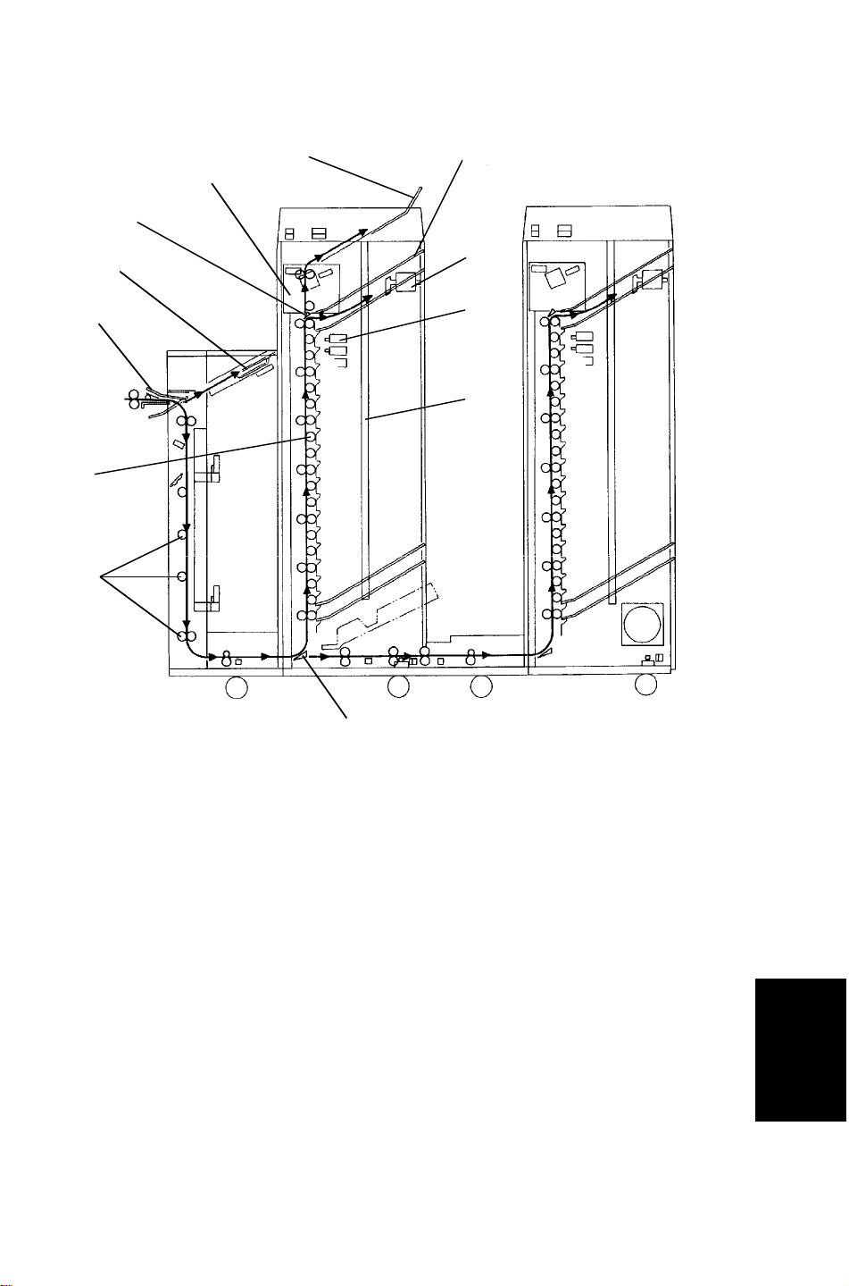
1.2 MECHANICAL COMPONENT LAYOUT
1
2
12
3
11
10
4
5
6
9
8
7
1. Staple Unit
7. Relay Gate
2. Proof Tray
3. Bins
4. Jogger
5. Bin Solenoids
6. Side Bar
8. Diagonal Transport Rollers
9. Distribution Rollers
10. By-pass Tray Gate
11. By-pass Tray
12. Bin Gate
Sorter Stapler
3
Page 5
6 March 1992 OVERALL MACHINE INFORMATION
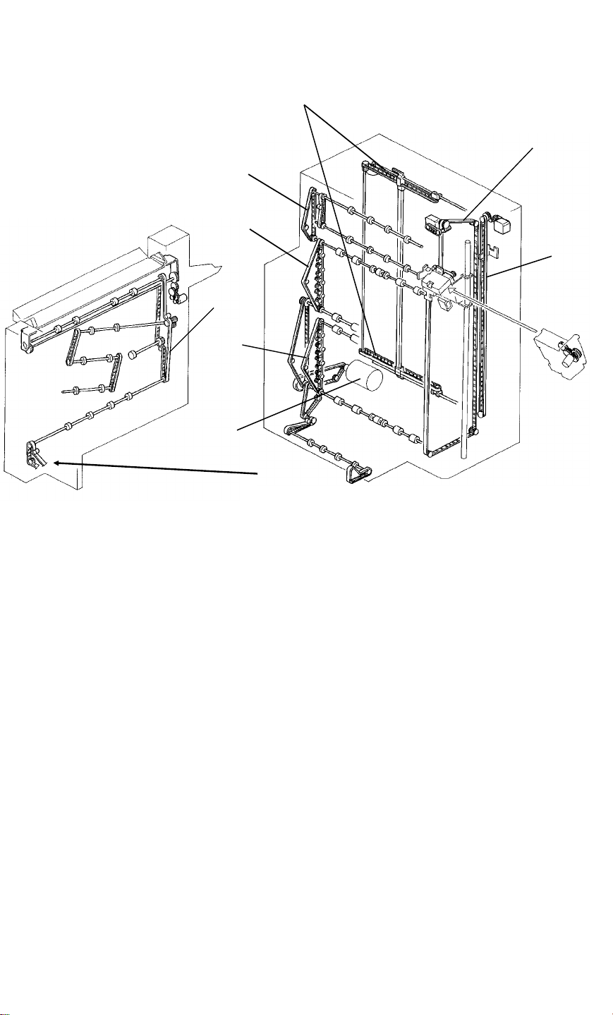
1.3 DRIVE LAYOUT
6
5
7
8
4
1
2
3
1. Diagonal Transport Drive Belt
2. Bin Drive Belt (1st to 10th)
3. Main Motor
4. Jogger Unit Drive Belt
5. Staple Unit
6. Side Bar Drive Belt
7. Proof Tray Exit Roller Drive Belt
8. Bin Drive Belt (11th to 20th)
4
Page 6

OVERALL MACHINE INFORMATION 6 March 1992
1.4 ELECTRICAL COMPONENT DESCRIPTION
Symbol Name Function Index No.
Motors
Main Drives the diagonal transport unit, horizontal
M1
M2
M3
M4
M5
M6
M7
M8
transport unit, and distribution unit through
timing belts.
Staple Unit
Positioning
Jogger Unit
Positioning
Side bar Drives the side bar side to side according to
Grip Drives the gripper forward into the bin to grip
Staple Feeds the staples and drives the stapler
Jogger Drives the jogger arm to align the copy. (dc
By-pass Tray Gate Drives the by-pass tray gate up or down to
Drives the staple unit up or down to the
appropriate bin. (dc stepper)
Drives the jogger unit up or down to the
appropriate bin. (dc stepper)
the paper size. (dc stepper)
the copies and bring them to the stapling
position. (dc brush)
hammer. (dc brush)
stepper)
switch the paper delivery tray.
22
5
9
1
12
15
18
36
Switches
SW1
SW2
SW3
Circuit Boards
PCB1 Main Controls overall sorter stapler functions. 31
PCB2
PCB3
PCB4
Solenoids
SOL1~20
SOL21
SOL22
Front Door De-energize the main motor and cuts 24 V
line when the front door is open.
Vertical Transport
Door
Horizontal
Transport Door
DC Power Supply Convert ac voltage to 5 V dc and 24 V dc to
Bin Solenoid
Control 1
Bin Solenoid
Control 2
Bin Opens and closes the bin gate to direct the
Grip Opens and closes the bin gate to drive the
Pressure Release Releases pressure of the brake roller when
De-energize the main motor when the vertical
transport door is open.
Informs the main board if the cover is open.
supply power to all dc components.
Interfaces between the bin solenoids 1 ~ 10
and the main board.
Interfaces between the bin solenoids 11 ~ 20
and the main board.
copies into the appropriate bin.
grippers to grip copies on the bins.
the paper is fed lengthwise.
8
6
20
26
28
30
27
Sorter Stapler
14
38
5
Page 7

6 March 1992 OVERALL MACHINE INFORMATION
Symbol Name Function Index No.
SOL23
Relay Solenoid Turn the relay gate to transport the copy to
the 2nd sorter.
43
Sensors
S1
S2
Entrance Detects paper jams at the entrance of the
diagonal transport unit.
Registration Detects paper jams at the horizontal transport
unit.
37
21
S3 Proof Tray Exit Detects paper jams at the proof tray exit. 2
S4
S5
S6
S7
Bin/Jam (LED) Detects if paper is in the bin.
Detects paper jams at the bin.
Bin/Jam (Photo Tr) Detects if paper is in the bin.
Detects paper jams at the bin.
Staple Unit H.P. Detects if the staple unit is in the home
position.
Jogger Unit H.P. Detects if the jogger unit is in the home
position.
3
19
4
10
S8 Grip H.P. Detects if the gripper is in the home position. 11
S9
S10
Hammer H.P. Detects if the staple hammer is in the home
position.
Jogger H.P. Detects if the jogger arm is in the home
position.
13
17
S11 Side Bar H.P. Detects if the side bar is in the home position. 33
S12
S13
S14
Tray Gate H.P. Detects if the by-pass tray gate is in the home
position.
Tray Gate Upper
Position
Staple Unit
Detects if the by-pass tray gate is in the upper
position.
Detects the position of the staple unit.
Position
34
35
32
S15 Paper Detect if copies are under the hammer. 7
S16 Staple End Detects if the staple is present. 16
S17
Diagonal
Transport Door
Detects if the diagonal transport door is open.
39
Open
S18 Timing Supplies timing pulses to the main board. 29
S19
Relay Unit Cover
Open
Detects if the relay unit cover is open.
41
S20 Relay Sensor Detects paper jam at the relay unit. 42
Capacitor
C1 Main Motor Protects the PCB’s from induced current. 23
Noise Filter
NF1
Noise Filter Removes electrical noise generated by the
copier and the sorter stapler.
6
25
Page 8

OVERALL MACHINE INFORMATION 6 March 1992
Symbol Name Function Index No.
Relay
RA1 Main Controls main power. 24
Transformer
TF1 2nd Sensor Detects paper jam at the relay unit. 42
Sorter Stapler
7
Page 9
6 March 1992 OVERALL MACHINE INFORMATION
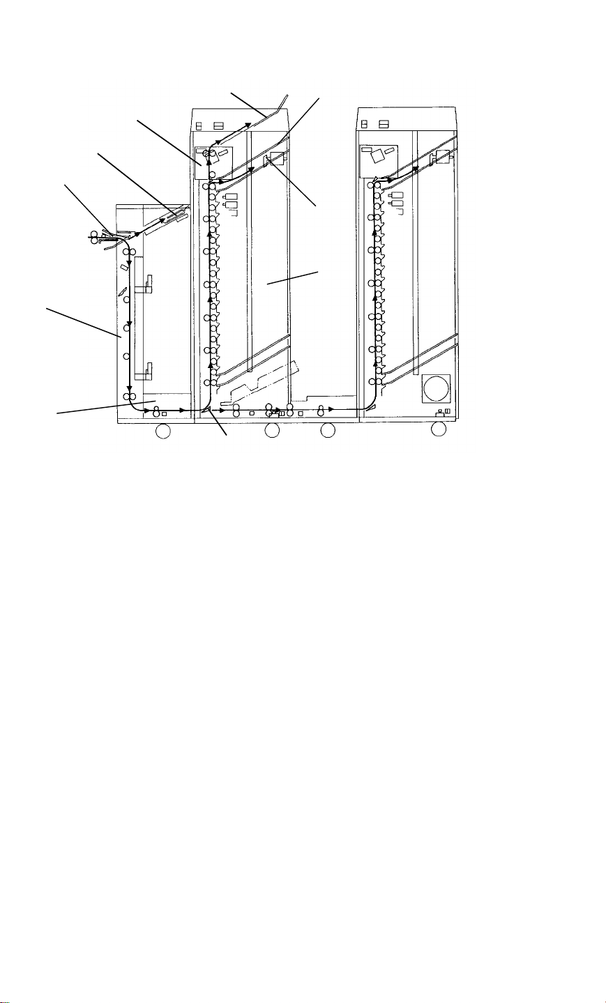
1.5 BASIC OPERATION
[C]
[G]
[I]
[A]
[B]
[H]
[F]
[D]
[E]
[J]
Copies exiting the copier enter the sorter or the by-pass tray [A] depending
on the by-pass tray gate [B] position. In normal operation, copies are sent to
the sorter, if paper jams occur in the sorter, the remaining papers in the
copier are fed to the by-pass tray.
If sort/stack mode is not selected, copies are delivered to the proof tray [C]
through the diagonal transport unit [D], the horizontal transport unit [E], and
the distribution unit [F].
When sort/stack mode is selected, copies are delivered to the bins [G] in
order.
The copies in the bins are arranged by the jogger arm [H].
If staple mode is selected, when the last page of the original is delivered to
the 1st bin, the staple unit [I] starts stapling the copies in each bin.
The 1st sorter has capacity to hold 20 sorted copies.
If the 2nd sorter is installed next to the 1st sorter, an additional 20 sorted
copies can be sorted.
After the 20th copy is fed to the distribution unit of the 1st sorter, the relay
gate [J] moves to the upper position and the 21st copy is transported to the
2nd sorter. After the final copy of the designated number has passed under
the relay gate, the relay gate moves down to transport copies to the bins of
the 1st sorter again.
8
Page 10
SECTIONAL DESCRIPTION 6 March 1992
2. SECTIONAL DESCRIPTION
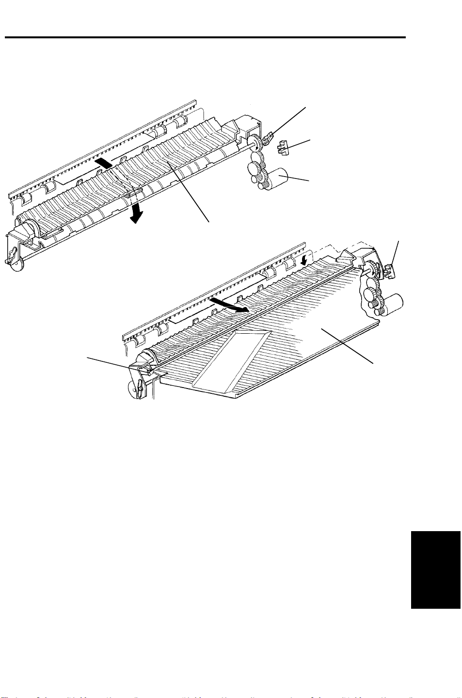
2.1 PAPER DELIVERY SWITCHING
[D]
[F]
[C]
[A]
[E]
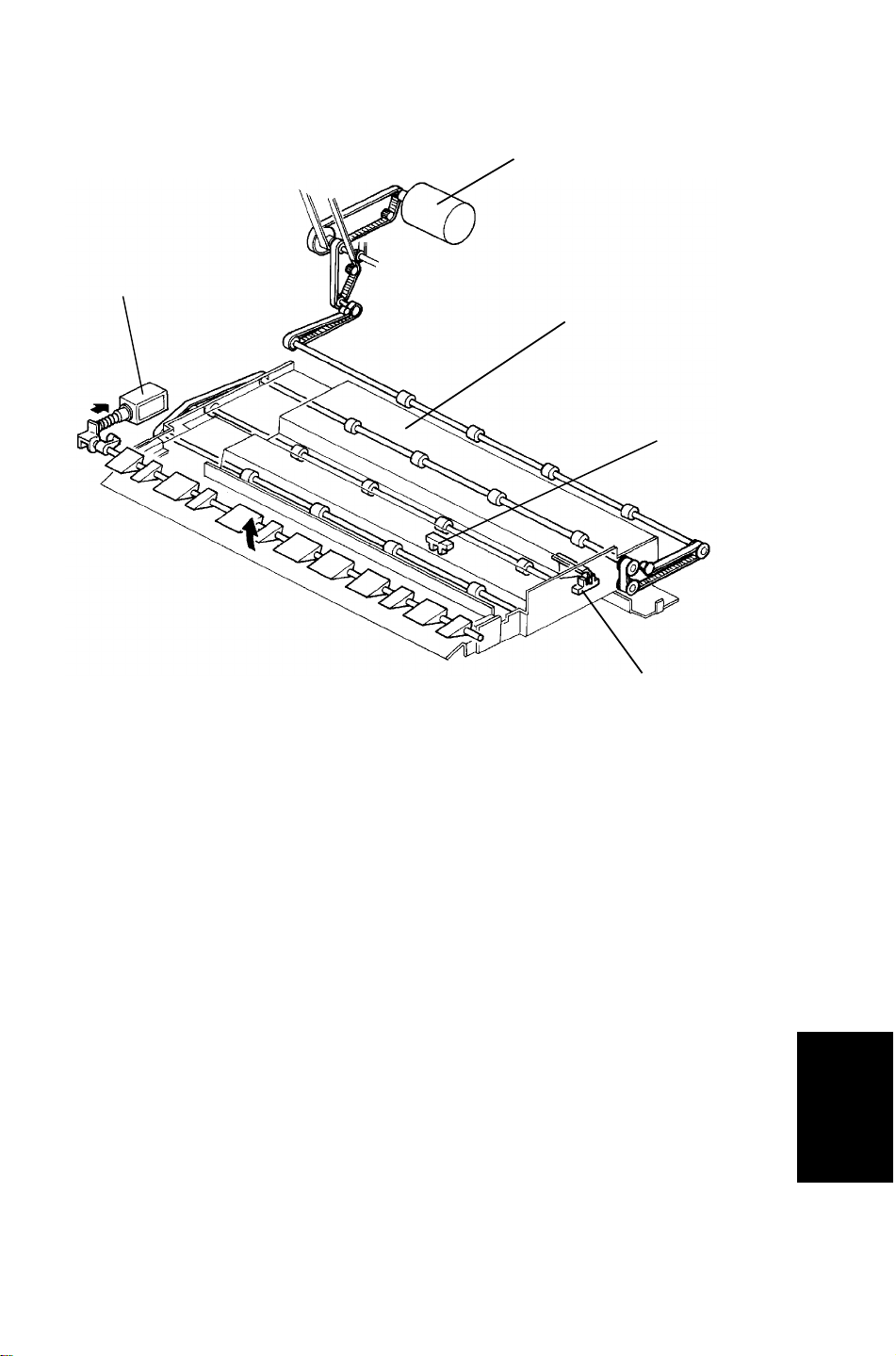
Depending on the by-pass tray gate [A] position, paper fed from the copier
enters either the sorter or the by-pass tray [B].
The by-pass tray gate is driven by the by-pass tray gate motor [C]. Under
normal operating conditions, the by-pass tray gate is in the home position
(H.P. sensor [D] is actuated) to deliver copies to the sorter. If a sorter paper
jam occurs, the gate rotates on its shaft [E] until the upper tray gate position
sensor [F] is actuated and stops.
[B]
[F]
Sorter Stapler
9
Page 11
6 March 1992 SECTIONAL DESCRIPTION
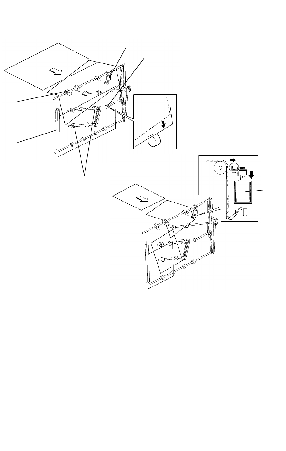
2.2 DIAGONAL TRANSPORT
[A]
[B]
[E]
[D]
[C]
[E]
Paper entering the diagonal transport unit is transported down to the
horizontal transport unit. The front side of the paper advances more than the
back side due to the front transport roller [A] being larger than the back
rollers. This causes the paper to skew as it enters the diagonal transport unit.
This skew prevents the diagonal transport guide [B] from catching the edge of
the copies.
The paper is then moved to the front by the diagonal transport rollers [C].
Where it is aligned as it is guided by the diagonal transport guide [B].
The brake roller [D] prevents the rear side of the paper from falling forward.
If the paper is traveling lengthwise, the pressure release solenoid [E] turns on
to prevent over skewing.
10
Page 12
SECTIONAL DESCRIPTION 6 March 1992
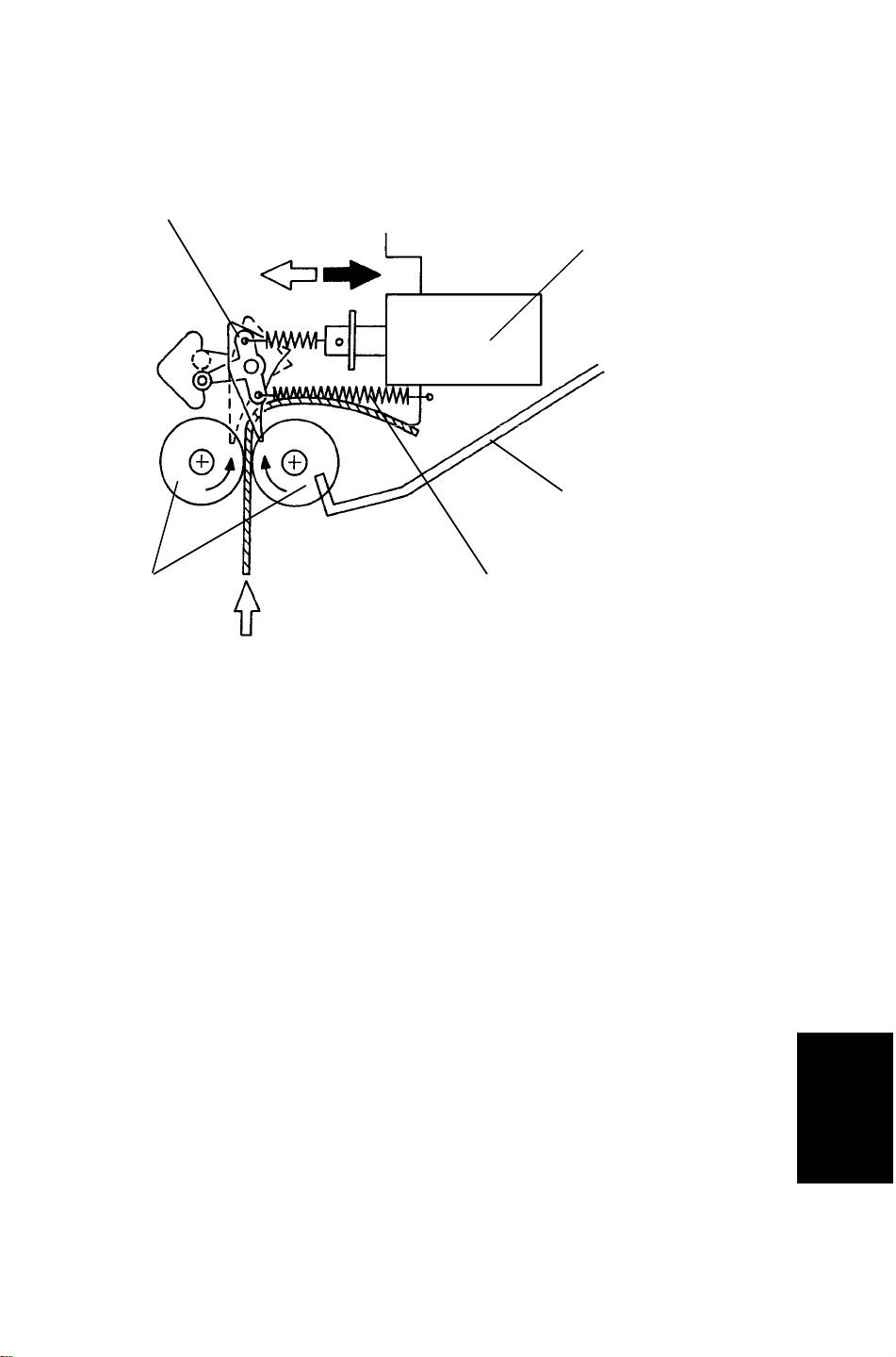
2.3 SORTING
[D]
[B]
[E]
[C][A]
The distribution section has the distribution rollers [A], 20 bin gates, and 20
bin solenoids.
When a bin gate solenoid [B] is off, the return spring [C] holds the bin gate [D]
out of the paper path, allowing the copies to pass to the upper bin.
The appropriate bin gate solenoid turns on and opens the bin gate. The other
solenoids are off. The copies go to the bin [E] through the gate.
11
Sorter Stapler
Page 13
6 March 1992 SECTIONAL DESCRIPTION
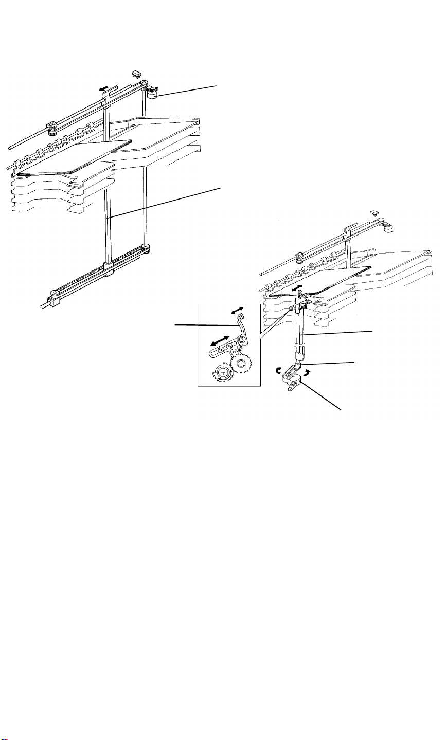
2.4 PAPER JOGGING
[B]
[A]
[C]
[F]
[E]
[ D]
Ordinarily, the side bar [A] is in the home position. It moves to within 10 mm
of the rear of the selected paper size. The side bar is driven by the side bar
motor [B] through the gears and a timing belt.
The jogger arm [C] home position is 10 mm in front of the paper.
After the paper passes the jam sensor, the jogger arm moves twice due to
the forward and reverse rotation of the jogger motor [D]. Jogger arm
movement is controlled through the link [E] and jogger bar [F].
The reverse rotation of the jogger motor prevents motor lock caused by an
overly stiff paper stack. Even if the overly stiff paper interferes with the jogger
arm movement, the arm returns to its home position via the reverse rotation
of the jogger motor.
12
Page 14
SECTIONAL DESCRIPTION 6 March 1992
2.5 STAPLING
[C]
[A]
[E]
[D]
[B]
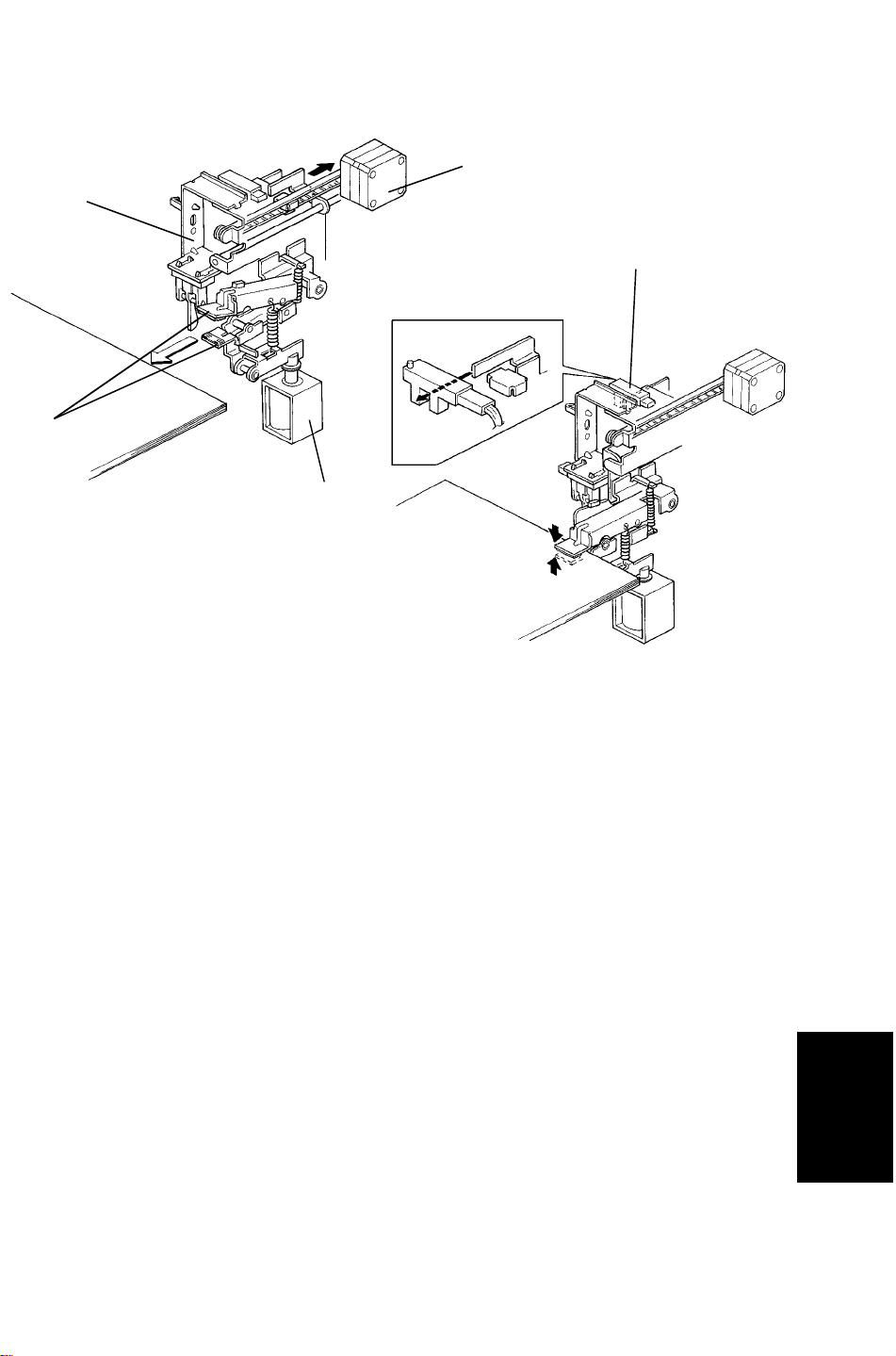
2.5.1 Gripper
The grip unit [A] grips and moves the jogged paper to the staple position and
returns the stapled paper to the bin.
The grip solenoid [B] and grip motor [C] are built into the grip unit. The motor
moves the grippers [D] back and forth, and the solenoid [B] controls paper
clamping.
When the grippers reach the paper in the bin, the grip solenoid turns on and
the grippers grasp the paper.
The lower gripper arm has a shorter stroke to prevent it from disturbing the
jogged paper in the bin.
Paper gripped by the grippers is moved by the grip motor into stapling
position.
Resetting the main PCB DIP SW101-1 to 101-4 adjusts the stapling position
(0.5 mm increments).
The stapled paper (held by the gripper arms throughout stapling) is returned
to its original position. The grip solenoid turns off to release the stapled
paper, and the gripper arms return to their original position.
The grip H.P. sensor [E] confirms that the grip unit has returned to its home
position.
Sorter Stapler
13
Page 15
6 March 1992 SECTIONAL DESCRIPTION
[A]
[B]
[C]
[E]
[D]
[F]
2.5.2 Stapler
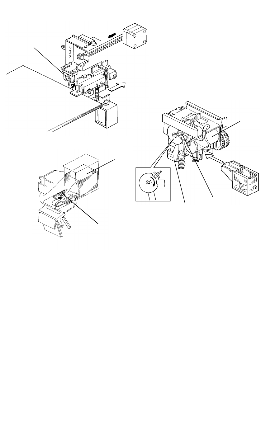
The paper sensor [A] prevents stapler operation when there is no paper in
position. Also, it detects staple error if the paper sensor remains actuated
when the stapler finishes its operation.
The staple motor [B] drives the stapling mechanism and transporting of the
staples from the cartridge [C].
The hammer H.P. sensor [D] checks if the staple hammer [E] is in the home
position.
The staple end sensor [F] checks if staples are present.
14
Page 16
SECTIONAL DESCRIPTION 6 March 1992
2.6 JOGGER UNIT POSITIONING
[A]
[B]
[C]
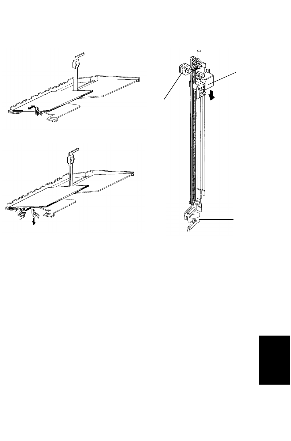
The jogger unit [A] vertical position is controlled by the stepper motor [B].
Depending on the rotation of the stepper motor [C], the jogger unit moves to
the appropriate bin.
When the main switch is turned on, the jogger unit will stop in its home
position. During sorter operation, the motor starts rotating when jogger
operation at any bin is complete. This lowers the jogger unit until it reaches to
the next bin and then the motor stops.
When jogger operation for a designated number of copies is complete, the
motor rotates to raise the jogger unit back to its home position.
Sorter Stapler
15
Page 17
6 March 1992 SECTIONAL DESCRIPTION
2.7 STAPLE UNIT POSITIONING
[C]
[G]
[D]
[H]
[E]
[F]
[A]
[B]
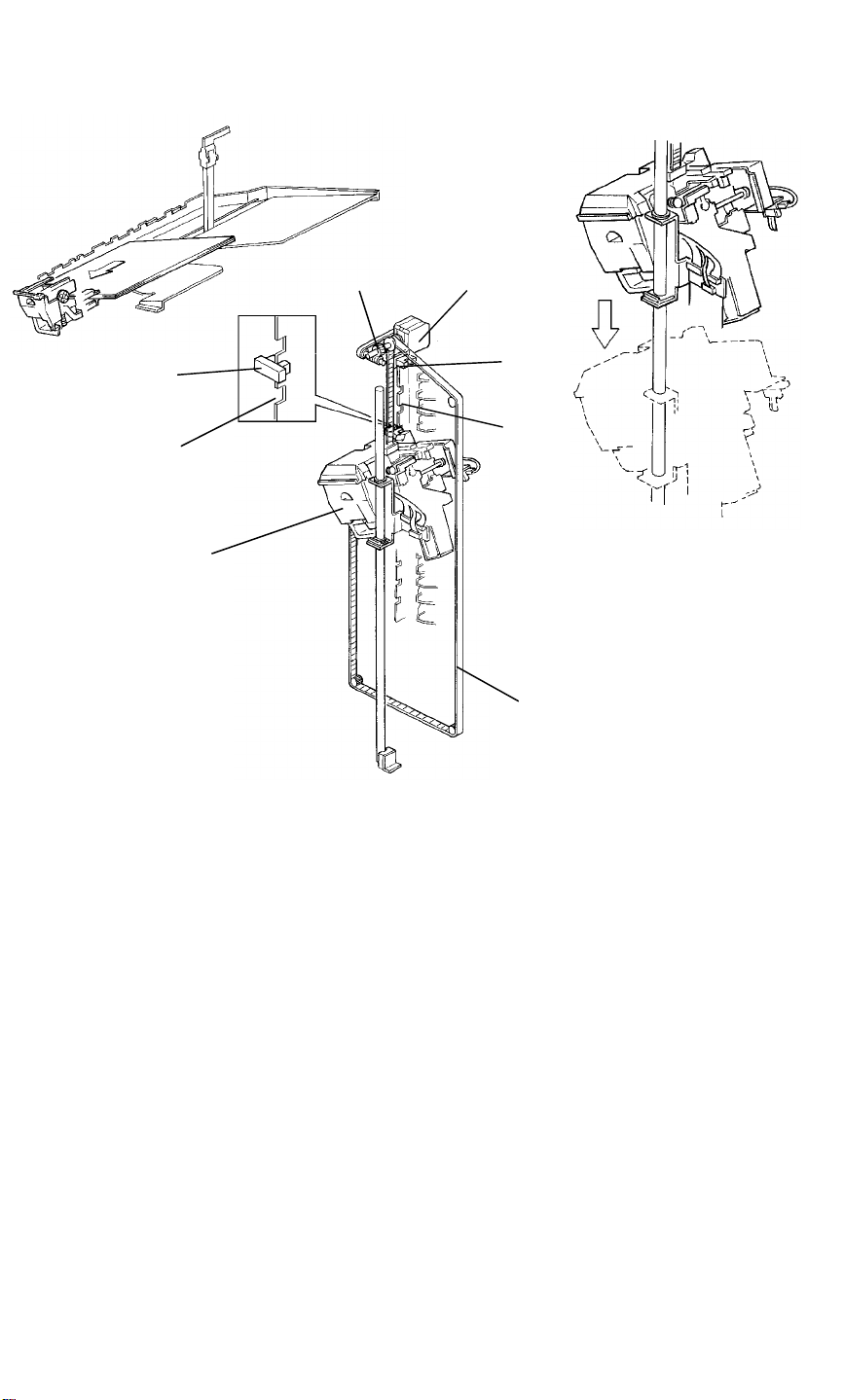
The staple unit [A] is hanging on the timing belt [B]. Due to the weight of this
staple unit, accurate positioning is ensured by using worm gear [C] which
transmits the staple positioning motor [D] rotation to the timing belt.
The bracket [E] guiding the staple unit has notches [F] which the staple unit
position sensor [G] senses.
Initially, the staple unit is beside the top bin. When stapling at the first bin is
completed, the staple unit positioning motor [D] energizes to move the staple
unit to the next bin where stapling is repeated.
When stapling at the last bin is completed, the motor [D] rotates to raise the
staple unit back to its home position. The staple positioning motor stops when
the staple unit home position sensor [H] is actuated.
Raising the staple unit requires more torque than lowering it. Thus the motor
speed when raising the staple unit will be approximately half of the lowering
speed.
16
Page 18
SECTIONAL DESCRIPTION 6 March 1992
2.8 1ST AND 2ND SORTER CONNECTION
[B]
[A]
[D]
[C]
[E]
When the 2nd sorter is connected, paper must be relayed from the 1st sorter
to the 2nd sorter. A relay solenoid [A] has been added to the 1st sorter for
this purpose.
A relay unit is also added to the 1st sorter to transport paper to the 2nd sorter.
The relay unit is driven by the 2nd sorter main motor [B].
The relay sensor [C] detects paper jams at the relay unit.
The relay unit cover [D] is provided to enable removal of misfed papers.
The photosensor [E] detects if the cover [D] is open.
Sorter Stapler
17
Page 19
6 March 1992 SECTIONAL DESCRIPTION
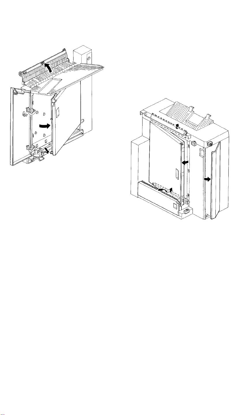
2.9 DOOR SWITCHES
Doors and guide plates are provided to enable removal of misfed papers.
Each door has a safety switch to detect opening and closing. These switches
also perform the jam reset function.
18
Page 20
SECTIONAL DESCRIPTION 6 March 1992
2.10 JAM DETECTION
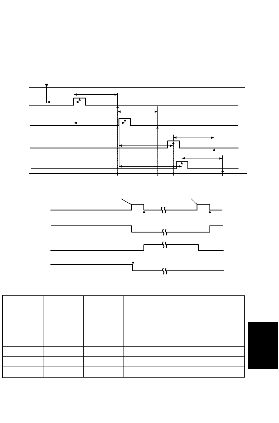
2.10.1 Jam Detection Condition
The jam detection timing is determined by pulses from the timing sensor. The
diagram below illustrates the timing interval in which each sensor detects
paper jams in operation.
Entrance
Sensor
Registration
Sensor
Jam
Sensor
Exit
Sensor
Jam Detection Timing
By-pass Tray
Gate Motor
Tray Gate HP
Sensor
Tray Gate Upper
Position Sensor
Paper Exit Signal from Copier
300 pls
340 pls
400 pls
Sorter Jam
280 pls
*1
436 pls
470 pls
Stop Signal
from Copier
280 pls
280 pls
OFF OFFOFF ON ONOFF ONON
Papers in
copier exit
Main Motor
*1. Jam detection timing depends on the bin position
Bin No. Pulses Bin No. Pulses Bin No. Pulses
proof 470 7 354 14 260
1 436 8 342 15 248
2 422 9 328 16 234
3 408 10 314 17 220
4 394 11 302 18 208
5 382 12 288 19 194
6 368 13 274 20 180
Staple failure is detected if the paper sensor is not de-energized after the
machine finishes returning the stapled paper to the bin.
19
Sorter Stapler
Page 21

6 March 1992 SECTIONAL DESCRIPTION
2.10.2 Machine Operation in Jam Conditions
a. When a paper jam occurs in the copier, the sorter stapler stops after
delivering papers in the sorter to the appropriate bins.
b. When a paper jam occurs in the sorter stapler, the by-pass tray gate
motor energizes and papers in the copier are delivered to the by-pass
tray.
c. When a staple failure is detected, the machine stops staple operation.
2.10.3 Jam Reset
a. If a paper jam occurs at the diagonal transport unit, the jam condition is
reset when the diagonal transport door is closed after removing the
misfed paper.
b. If a paper jam occurs in the sorter, the jam condition is reset when the
vertical transport door or the horizontal transport door is closed after
removing the misfed paper.
c. If a staple failure occurs, the jam condition is reset when the sorter front
door is closed after removing the unstapled paper.
2.10.4 Jam Recovery
Copies on the bin are counted by the jam sensor.
When the start key is pressed after misfed paper is removed, the machine
delivers the copies from the continuance bin.
20
Page 22

INSTALLATION PROCEDURE 6 March 1992
3. INSTALLATION PROCEDURE
3.1 1ST SORTER STAPLER
3.1.1 Accessories
1. Tray Extension.............................................. 1
2. Original Guard .............................................. 1
3. Upper Stay.................................................... 1
4. Lower Stay.................................................... 1
5. Harness Cover.............................................. 1
6. Front Door..................................................... 1
7. Lower By-pass Tray...................................... 1
8. Staple Cartridge............................................ 1
9. Leveling Shoe............................................... 2
10. M4 x 6 Screw................................................ 9
11. M4 x 8 Screw with Star Washer ................... 2
12. Installation Procedure................................... 1
13. NECR ........................................................... 1
21
Sorter Stapler
Page 23
6 March 1992 INSTALLATION PROCEDURE
[C]
[A]
[H]
[I]
[A]
[B]
[C]
[D]
[C]
[E] [F]
[I]
[F]
[G]
[J]
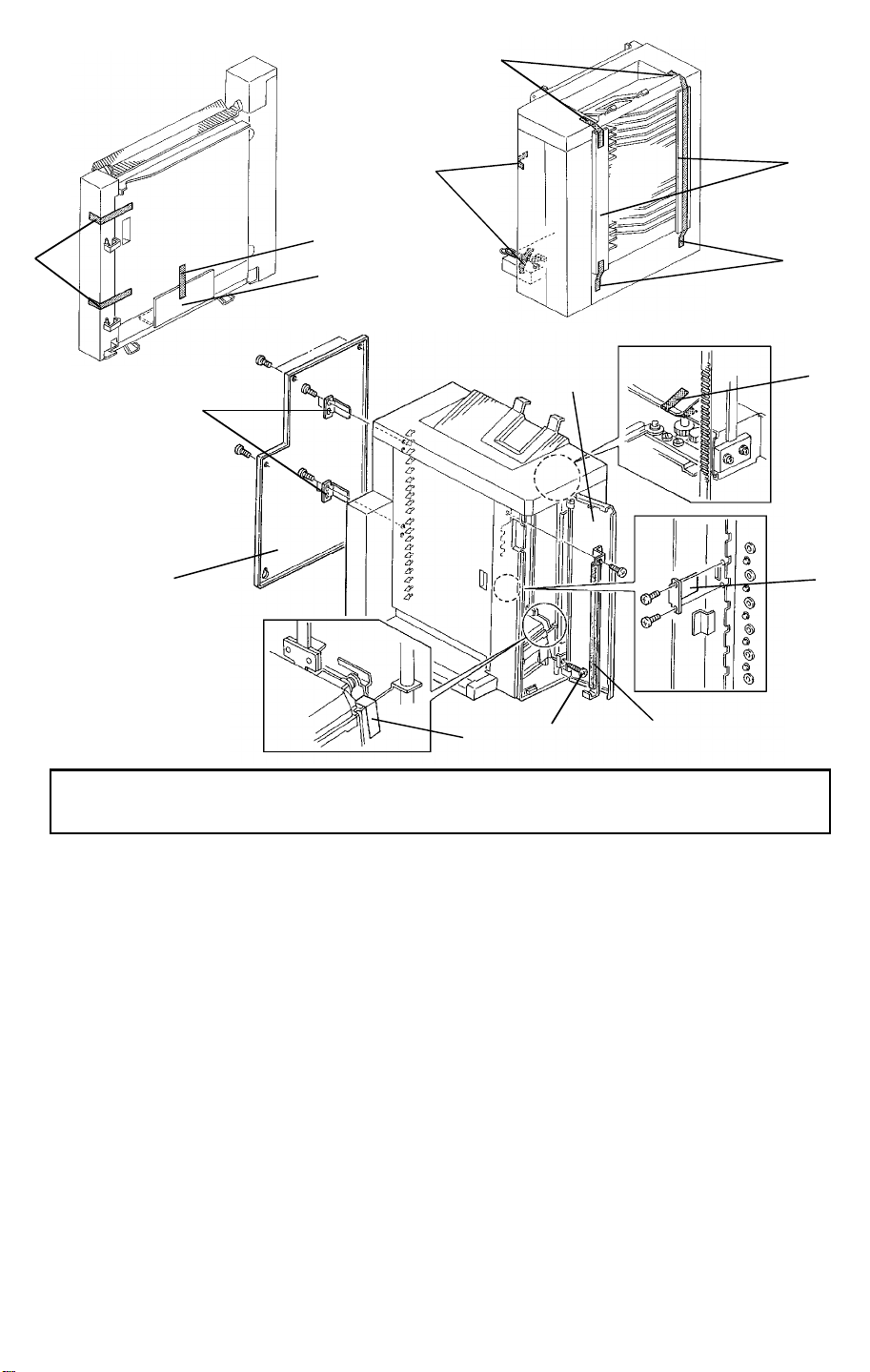
CAUTION: Unplug the copier power cord before starting the following
procedure.
1. Remove the strips of filament tape [A] and remove the cushion [B]
protecting the vertical transport door.
2. Remove the strips of filament tape [C] and remove the cushions [D]
protecting the bins.
3. Open the front door [E] and remove the strips of filament tape [F] fixing
the jogger unit and the grip unit.
4. Remove the screw [G] fixing the staple unit.
5. Remove the rear cover [H] (6 screws).
6. Remove the three brackets [I] supporting the vertical transport cover (2
screws each).
7. Remove the bracket [J] with the cushion supporting the bins (1 screw).
8. Reinstall the rear cover.
22
Page 24
INSTALLATION PROCEDURE 6 March 1992
[C]
[A]
[B]
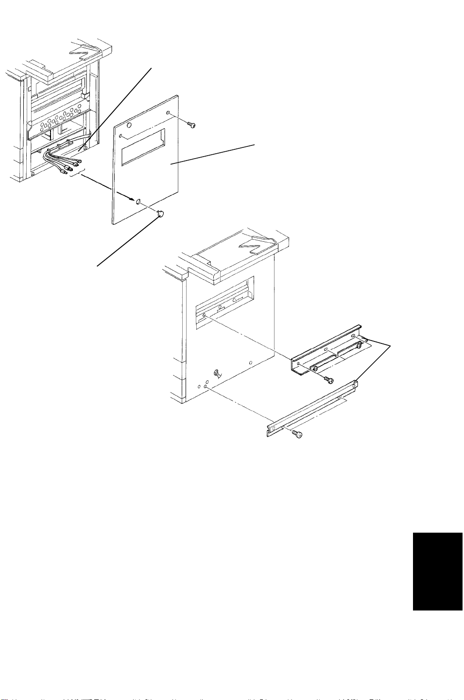
9. Remove the right cover [A] of the copier (2 screws) and the plastic cap
[B]. Reinstall the right cover passing the interface harness [C] (3
connectors and 1 ground wire) through the lower hole of the right cover.
10. Fix the upper and lower stays [D] (5 screws) to enable fixing of the
diagonal transport unit.
[D]
Sorter Stapler
23
Page 25
6 March 1992 INSTALLATION PROCEDURE
[H]
[F]
[D]
[E]
[A]
[B]
[G]
[C]
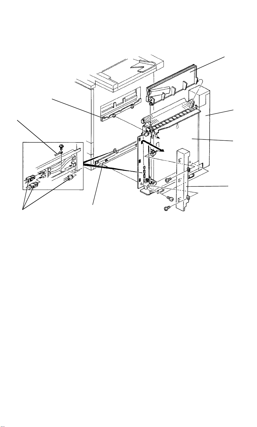
11. Open the diagonal transport door [A] and remove the front cover [B] (2
screws) of the diagonal transport unit.
12. Set the connectors of the interface harness [C] from the copier to the
diagonal transport unit [D].
13. Fix the ground line [E] to the diagonal transport unit (M4 x 8 screw with a
star washer).
14. Hook the diagonal transport unit on the upper stay [F]. Then fix the unit to
the lower stay [G].
15. Install the lower by-pass tray [H].
24
Page 26
INSTALLATION PROCEDURE 6 March 1992
[A]
[B]
[E]
[F]
[G]
[D]
[H]
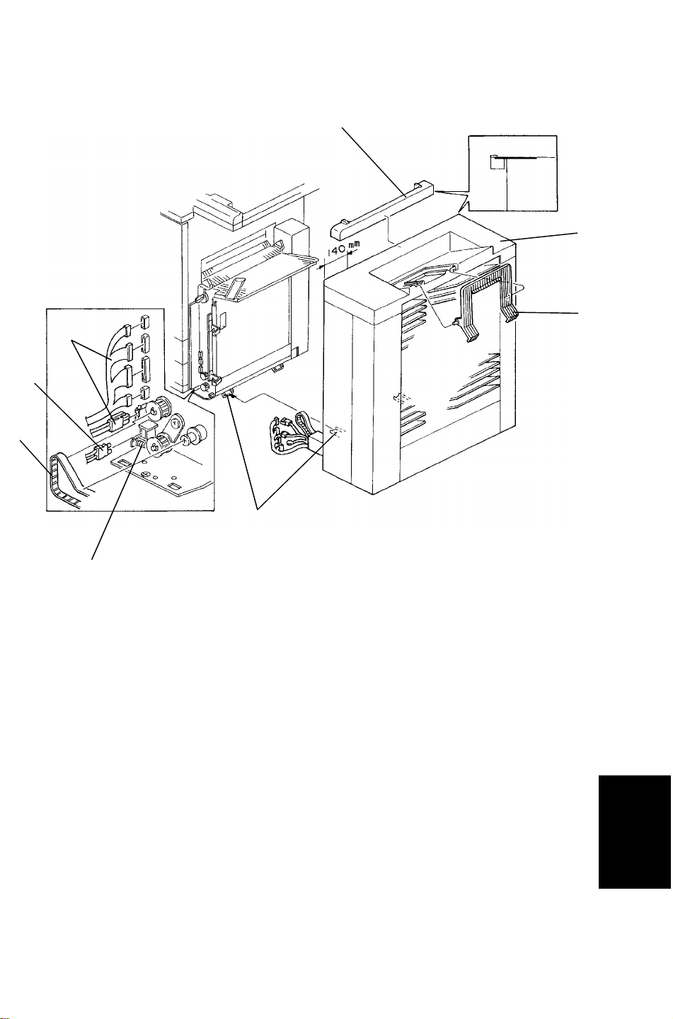
16. Stick the original guard [A] onto the upper cover [B] of the 1st sorter.
NOTE: Stick it 140 mm from the end of the cover.
17. Install the tray extension [C].
[C]
18. Join the 1st sorter to the diagonal transport unit, pressing the 1st sorter
until the two latches [D] lock together.
19. Connect the harness connectors [E] and the optical fiber cable [F].
20. Set the timing belt [G] and hook the tension spring [H].
25
Sorter Stapler
Page 27
6 March 1992 INSTALLATION PROCEDURE
[B]
[D]
[E]
[C]
[A]
[F]
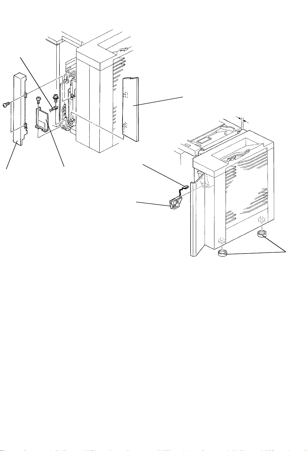
21. Install the harness cover [A] (2 M4 x 6 screws).
22. Fix the ground line [B] of the diagonal transport unit (M4 x 8 with star
washer).
23. Install the front cover [C] of the diagonal transport unit (2 screws) and set
the front door [D].
24. Open the front door of the sorter, remove the staple cartridge cover [E],
and set the staple cartridge [F].
25. Put the two leveling shoes [G] under the feet. Confirm that the sorter is
parallel to the copier.
26. Turn on the main switch of the copier and test the operation of the sorter
stapler.
[G]
NOTE: The stapler will not staple for the first 10 or so copies until the
first staple from the cartridge reaches the proper position for
stapling.
26
Page 28

6 March 1992 INSTALLATION PROCEDURE
3.2 2ND SORTER STAPLER
3.2.1 Accessories
1. Relay Unit..................................................... 1
2. Optical Fiber Cable....................................... 1
3. Tray Extension.............................................. 1
4. Interface Board............................................. 1
5. Joint Bracket................................................. 1
6. Harness Cover Bracket ................................ 1
7. Motor Cover.................................................. 1
8. Bin Bottom Bracket....................................... 1
9. Relay Gate Solenoid..................................... 1
10. Staple Cartridge............................................ 1
11. Leveling Shoe............................................... 2
12. Bushing......................................................... 1
13. Relay Connector........................................... 1
14. Decal............................................................. 1
15. M4 x 6 Philips Pan Head Screw................... 2
16. M4 x 6 Truss Head Screw............................ 1
17. M4 x 6 Screw with Washer........................... 2
18. M4 x 8 Screw with Star Washer ................... 1
19. M4 x 6 Screw with Spring Washer ............... 3
20. M4 x 8 Double Washer Screw...................... 1
21. Flat Head Screw........................................... 1
22. Installation Procedure................................... 1
23. NECR ........................................................... 1
27
Sorter Stapler
Page 29
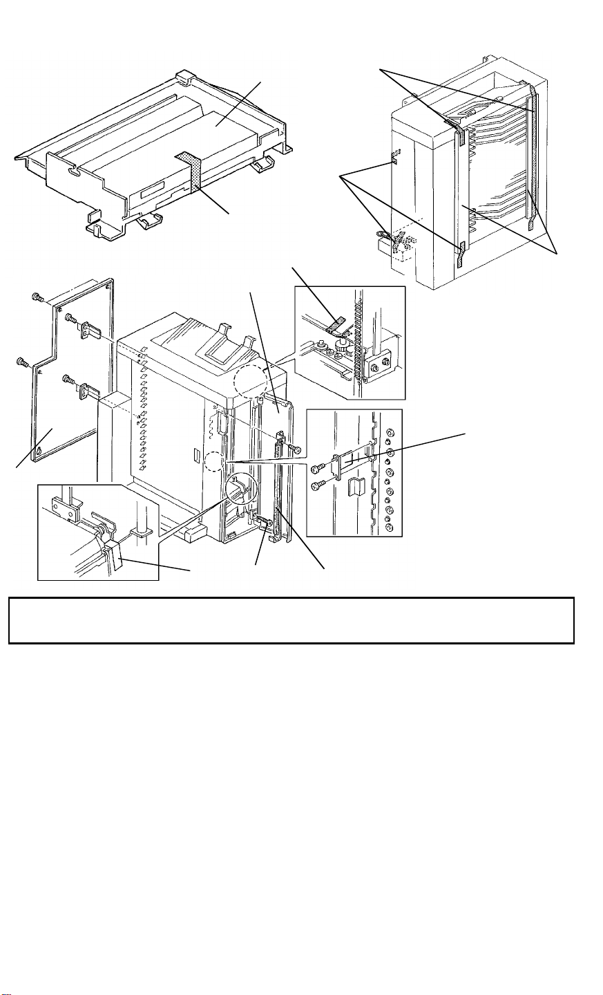
INSTALLATION PROCEDURE 6 March 1992
[I]
[A]
[E]
[B]
[F]
[C]
[C]
[D]
[I]
[H]
[F]
[G]
[J]
CAUTION: Unplug the copier power cord before starting the following
procedure.
1. Remove the strip of filament tape [A] fixing the relay unit cover [B].
2. Remove the strips of filament tape [C] and remove the cushions [D]
protecting the bins.
3. Open the front door [E], remove the strips of filament tape [F] fixing the
jogger unit and the grip unit.
4. Remove the screw [G] fixing the staple unit.
5. Remove the rear cover [H] (6 screws).
6. Remove the three brackets [I] supporting the vertical transport cover (2
screws each).
7. Remove the bracket [J] with the cushion supporting the bins (1 screw).
28
Page 30
6 March 1992 INSTALLATION PROCEDURE
[I]
[C]
[H]
[B]
[A]
[F]
[D]
[G]
[E]
[L]
[K]
[J]
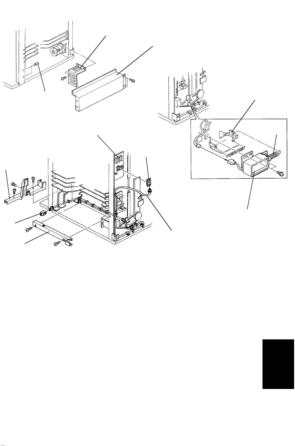
8. Remove the rear cover of the 1st sorter (6 screws).
9. Remove the lower right cover [A] (2 screws), motor cover [B] (2 screws),
and 2 studs [C] from the 1st sorter. Install them on the 2nd sorter.
10. Hook the spring [D] of the relay gate solenoid [E] packed with the 2nd
sorter to the relay gate lever [F] and fix the relay gate solenoid (2 screws
with washer and 1 connector).
11. Set the interface board [G] packed with the 2nd sorter on the CN200 of
the 1st sorter main board [H] so that the notch of the interface board is up.
12. Remove the front harness cover [I] (3 screws) and inner harness cover [J]
(2 screws). Connect the optical fiber cable [K] packed with the 2nd sorter
to the interface board and run the cable as shown in the illustration.
13. Install the relay connector [L] packed with the 2nd sorter to the end of the
optical fiber cable [K].
Sorter Stapler
14. Reinstall the inner harness cover [J].
29
Page 31
INSTALLATION PROCEDURE 6 March 1992
[C]
[A]
[B]
[E]
[F]
[D]
[G]
[K]
[J]
[H]
[I]
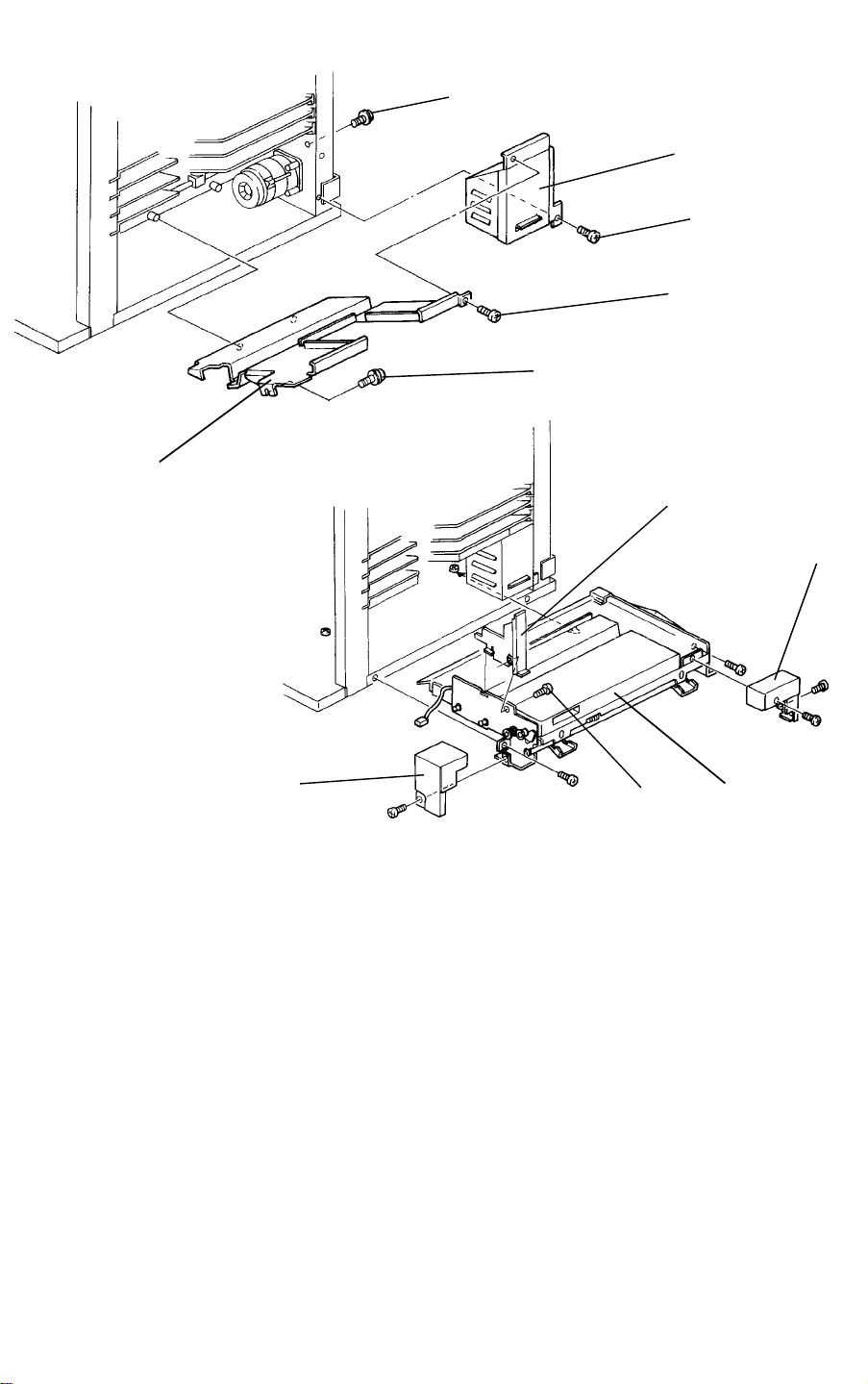
15. Install the motor cover [A] (M4 x 6 pan head screw [B] and M4 x 6 screw
with spring washer [C]) and the bin bottom bracket [D] (truss head screw
[E] and double washer screw [F]) both packed with the 2nd sorter to the
1st sorter.
16. Install the joint bracket [G] packed with the 2nd sorter (flat head screw
[H]) on the relay unit [I].
17. Remove the front cover [J] (1 screw) and the rear cover [K] (2 screw) of
the relay unit.
18. Install the relay unit in the 1st sorter (2 M4 x 6 screws with spring washer).
19. Reinstall the rear cover [K] of the relay unit and the rear cover of the 1st
sorter.
30
Page 32
6 March 1992 INSTALLATION PROCEDURE
[H]
[A]
[B]
[D]
[G]
[F]
[E]
[C]
[I]
[C]
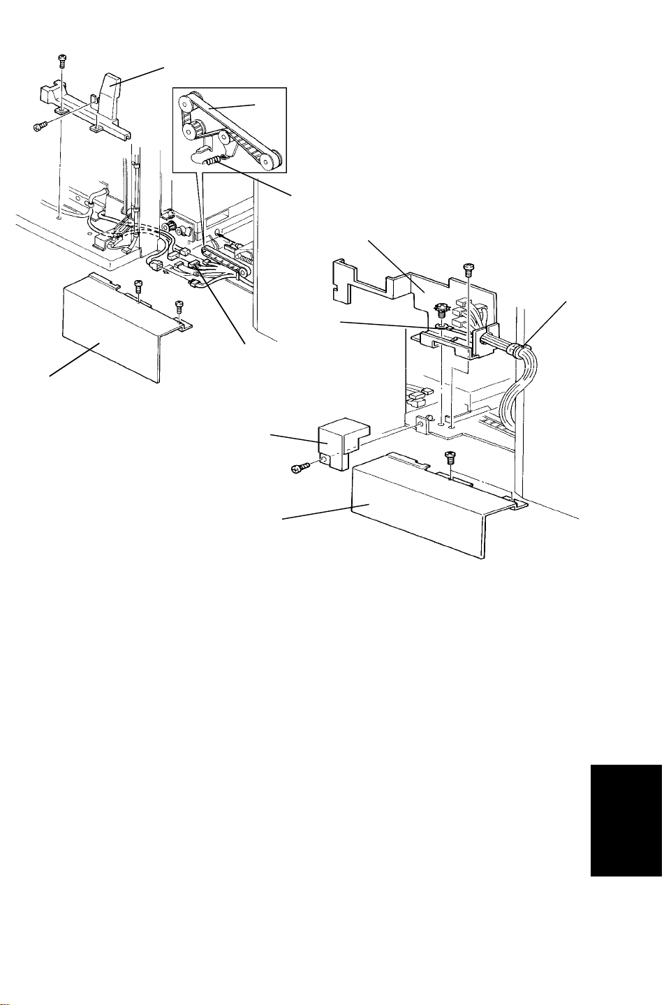
20. Join the 2nd sorter to the relay unit and set the timing belt [A]. Then hook
the spring [B] of the tension pulley bracket.
21. Remove the front cover [C] of the horizontal transport unit (2 screws).
22. Install the harness cover bracket [D] (1 screw, M4 x 6) packed with the
2nd sorter to the relay unit.
23. Connect three of the five connectors [E] from the 2nd sorter.
24. Fix the ground line [F] from the 2nd sorter to the relay unit (M4 x 8 with a
star washer).
25. Pass the harness through the cutout of the bracket [D] and install the
bushing [G] packed with the 2nd sorter.
26. Install the front cover [C] of the relay unit (2 screws).
27. Install the front harness cover [H] and the front cover [I] of the horizontal
transport unit.
Sorter Stapler
31
Page 33

INSTALLATION PROCEDURE 6 March 1992
[A]
[D]
[E]
[B]
[C]
28. 220/230/240 V version only
If the voltage of electrical power supply from wall outlets is 220 V or 240
V, change the voltage as follows:
a) Disconnect the input line [A] from the 230 V connector.
b) Connect the input line to the appropriate voltage (220 V or 240 V).
29. Reinstall the rear cover.
30. Put the two leveling shoes [B] under the feet. Confirm that the sorter is
parallel to the copier and the 1st sorter stapler.
31. Stick the decal [C] on the left rear cover of the copier beside the power
cord.
32. Turn on the main switch of the copier and test the operation of the sorter
stapler.
33. Open the front door of the sorter, remove the staple cartridge cover [D],
and set the staple cartridge [E].
NOTE: The stapler will not staple for the first 10 or so copies until the
first staple from the cartridge reaches the proper position for
stapling.
32
Page 34
6 March 1992 SERVICE TABLES
4. SERVICE TABLES
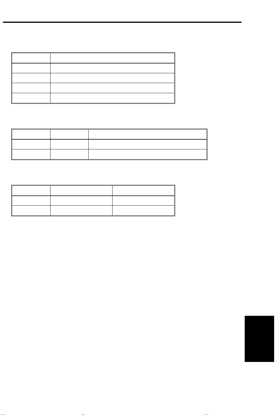
4.1 TEST POINT TABLE (Main Board)
Number Function
TP100 GND
TP101 5 V
TP102 24 V
TP103 Lower Staple Unit Trigger (SP Mode)
4.2 LED AND VARIABLE RESISTOR TABLE (Main Board)
LED No. VR No. Function
100 100 Adjusts jam sensor sensitivity
101 101 Adjusts bin sensor sensitivity
4.3 FUSE TABLE
Number Specification Location
Fuse 100 125 V 5 A Main Board
Fuse 1 125 V 5 A PSU
33
Sorter Stapler
Page 35

SERVICE TABLES 6 March 1992
4.4 DIP SW TABLE
DIP SW100 (MODE) SP mode
1 2 3 4 Function
0 0 0 0 Initial Normal Setting
1 0 0 0 Sorter Free Run
0 1 0 0 Staple Unit Free Run
1 1 0 0 Sorter & Staple Unit Free Run
0 0 1 0 Lower Staple Unit
0 0 0 1 Bin/Jam Sensor Adjustment
0: OFF 1: ON
1. "Sorter Free Run", "Staple Unit Free Run" or "Sorter & Staple Unit Free
Run" starts operation when the DIP switches are set as shown in the
table.
2. "Lower Staple Unit" starts operation when TP103 is short- circuited to
TP100 (GND), after setting DIP SW100-3 to 1.
3. Bin/Jam sensor can be adjusted by VR100 and VR 101 after setting DIP
SW100-4 to 1.
Operation
1. Sorter Free Run
1) Main motor turns on.
2) Side bar moves to the A4 position.
3) By-pass tray gate moves to the upper position.
4) Pressure release solenoid is energized for 2.4 seconds.
5) Bin solenoids turn on at the 1st bin continuing in order down to the
20th bin.
6) Jogger moves at each bin.
7) Machine stops operation for one second and then repeats the above
operation from 1).
2. Staple Unit Free Run
The sorter stapler repeats the staple operation in order from the 1st bin to
the 20th bin.
3. Sorter and Staple Unit Free Run
The sorter stapler works as if 20 sets of 2 A4 papers are present and
sorted in auto staple mode.
4. Lower Staple Unit
Staple unit lowers until it reaches to the 20th bin and stops.
34
Page 36
6 March 1992 SERVICE TABLES
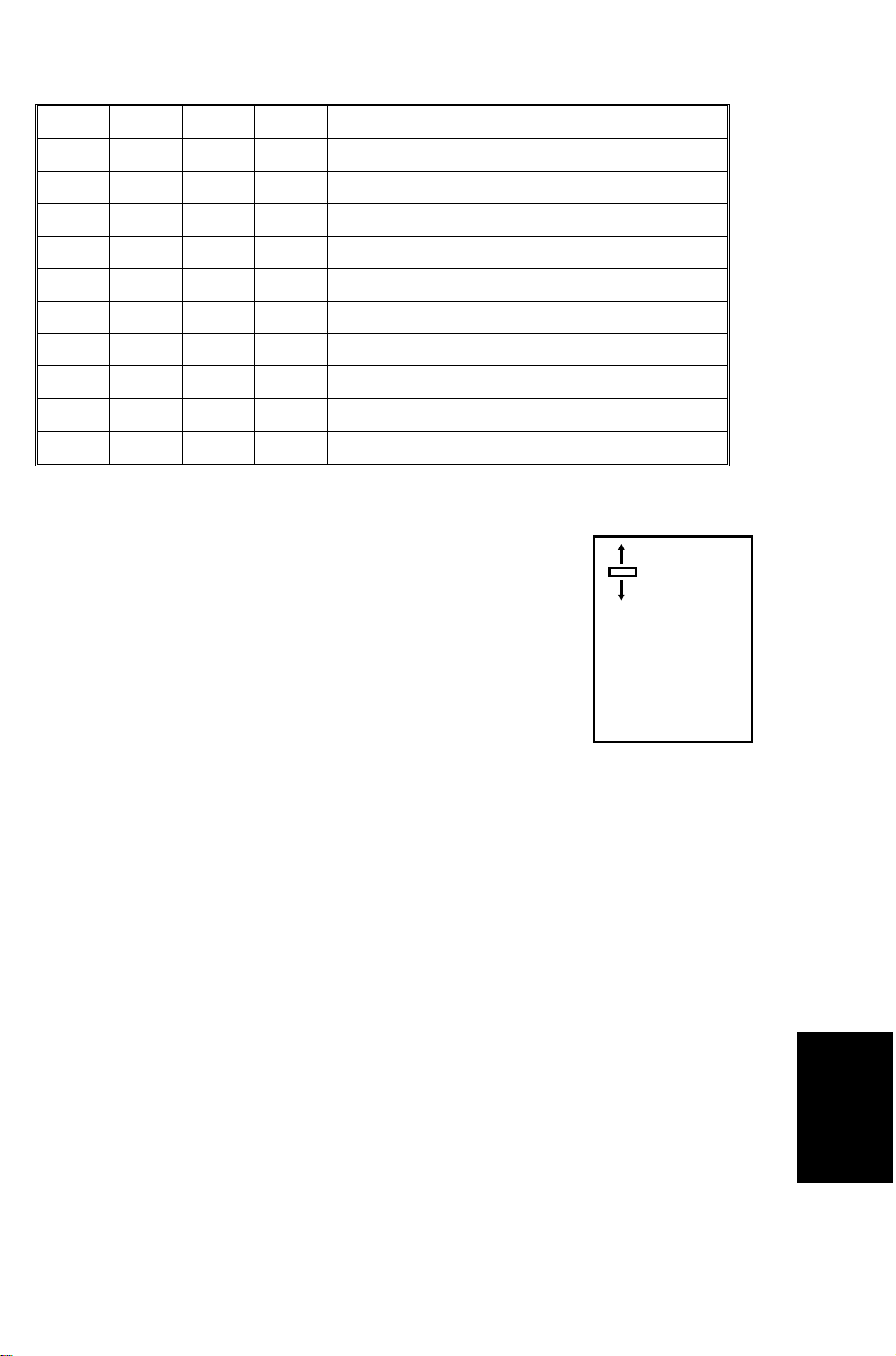
DIP SW101 (STAPLE) Staple position adjustment
1 2 3 4 Staple Position
0 0 0 -- Standard Value
1 0 0 0/1 0.5 mm shifted
0 1 0 0/1 1.0 mm shifted
1 1 0 0/1 1.5 mm shifted
0 0 1 0/1 2.0 mm shifted
1 0 1 0/1 2.5 mm shifted
0 1 1 0/1 3.0 mm shifted
1 1 1 0/1 3.5 mm shifted
-- -- -- 0 (+) Direction (farther from the edge)
-- -- -- 1 (--) Direction (closer to the edge)
0: OFF 1: ON --: Not concerned
DIP SW101-1, 101-2, and 101-3 determines the length
the staple position is shifted.
(--)
DIP SW101-4 determines the shift direction up or down.
(+)
35
Sorter Stapler
Page 37

SERVICE TABLES 6 March 1992
4.5 MAINTENANCE TABLE
Items Standard Procedure Tools
Rollers
Bins
Sensors
Bushings
Gears
Worm Gear
Clean the rollers if they are soiled. A cloth dampened with
alcohol
Clean the rollers if they are soiled. A cloth dampened with
alcohol
Clean the rollers if they are soiled. A cloth dampened with
alcohol
Lubricate the bushings if they
make noise.
Lubricate the gears if they make
Launa-40 oil or
equivalent
Grease G-501
noise.
Lubricate the worm gear if it
Mobil temp 78
makes noise.
36
Page 38
6 March 1992 REPLACEMENT AND ADJUSTMENT
5. REPLACEMENT AND ADJUSTMENT
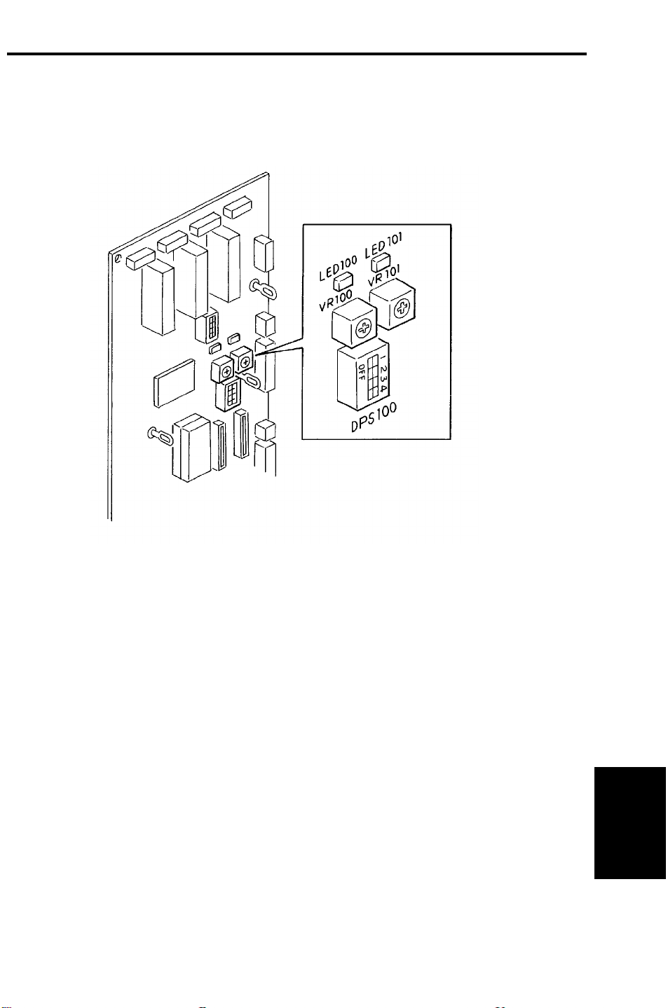
5.1 BIN/JAM SENSOR ADJUSTMENT
NOTE: This adjustment should be performed when the main board or the
bin/jam sensor is replaced.
1. Remove the rear cover.
2. Confirm that there is no paper on the bins.
3. Turn on the DIP SW100-4 on the main board.
4. Turn the VR100 and VR101 so that the LED100 and LED101 are at the
ON/OFF threshold (just turns off).
5. Turn off the DIP SW100-4.
37
Sorter Stapler
Page 39
REPLACEMENT AND ADJUSTMENT 6 March 1992
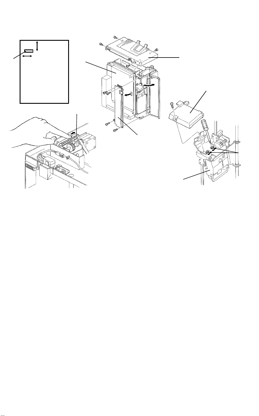
5.2 STAPLE POSITION ADJUSTMENT
Y
[A]
X
[C]
[B]
[G]
[F]
[D]
[E]
NOTE: This adjustment should be performed when the main board or staple
unit is replaced.
[H]
X Direction
1. Check the position of the staple [A] on the copy paper.
2. Remove the upper cover [B] (4 screws),open the vertical transport door
[C] and remove the left front cover [D] (4 screws).
3. Lower the staple unit [E] by manually turning the timing belt [F] of the
staple unit positioning motor in the direction of the arrow.
4. Remove the staple unit upper cover [G] (1 screw).
5. Loosen the two screws [H] and adjust the staple unit position.
6. Retighten the screws [H].
Y Direction
1. Check the position of the staple [A] on the copy paper.
2. Remove the rear cover.
3. Adjust the staple position by setting the DIP SW101.
38
Page 40
6 March 1992 REPLACEMENT AND ADJUSTMENT
5.3 SIDE BAR ADJUSTMENT
[A]
[B]
[D]
[C]
[E]
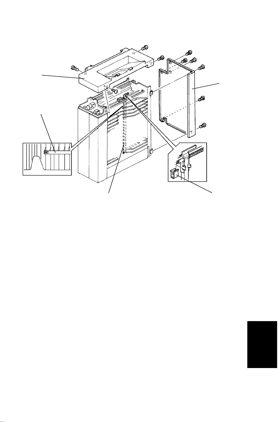
1. Remove the upper cover [A] and the rear cover [B].
2. Manually move the side bar [C] towards the front side of the bin side bar
slot [D], by turning the side bar motor manually.
3. Confirm that the side bar is parallel and contacts both the 1st and 20th
bin side bar slots front side.
4. If improper contact is observed between the 1st and 20th bin, remove the
timing belt clamp [E] and reposition the side bar position.
Sorter Stapler
39
Page 41
REPLACEMENT AND ADJUSTMENT 6 March 1992
5.4 BELT TENSION ADJUSTMENT
[B]
[C]
[D]
[A]
[E]
[F]
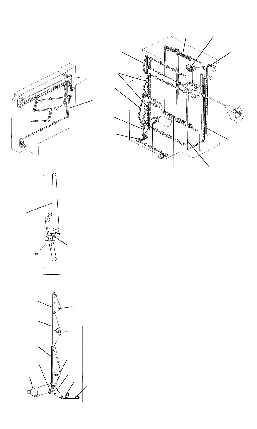
1. Detach the diagonal transport unit from
the copier, remove the rear cover of the
diagonal transport unit, and adjust the belt
[A] tension with tightener [a].
[A]
[G]
[L]
[L]
[K]
[J]
[I]
[H]
[B]
[C]
[D]
[G]
[e]
[d]
[E]
[a]
[c]
[f]
[b]
Standard [A]: 8 mm deflection at
100 ± 30 g pressure
2. Remove the rear cover of the distribution
unit and adjust the belt [B], [C], [D], [E],
[F], [G] tension with tightener [b], [c], [d],
[e], [f], [g].
<Standard>
[B]: 5 mm deflection at 80 ± 30 g pressure
[C]: 5 mm deflection at 140 ± 40 g pressure
[D]: 5 mm deflection at 100 ± 50 g pressure
[E]: 5 mm deflection at 100 ± 50 g pressure
[F]: The distance between the belt and the
[F]
bottom plate is 0.7 to 2.0 mm
[G]: 5 mm deflection at 100 ± 50 g pressure
40
Page 42
6 March 1992 REPLACEMENT AND ADJUSTMENT
[j]
[I]
[H]
[I]
[h]
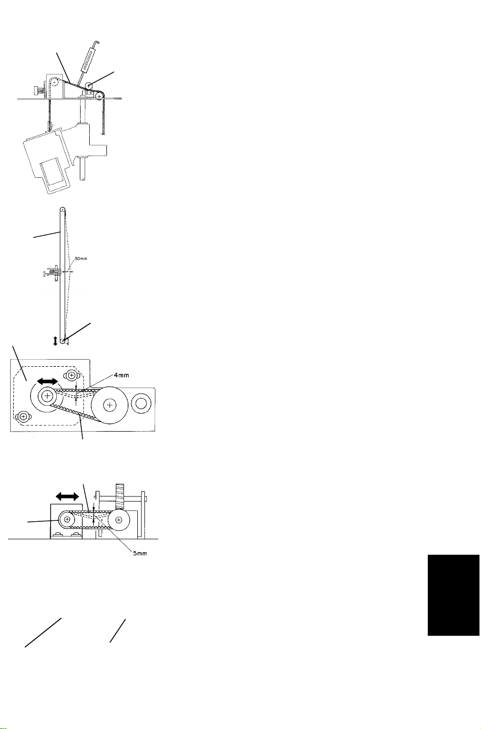
3. Remove the upper cover of the distribution
unit and adjust the belt [H] tension with the
tightener [L].
Standard [H]: 5 mm deflection at
170 ± 30 g pressure
4. Remove the upper cover and right cover
then adjust the belt [I] tension with the
tightener [i].
Standard [I]: 30 mm deflection at
200 ± 30 g pressure
[k]
[l]
[J]
[K]
[L]
5. Remove the upper cover and adjust the
belt [J] tension with the motor position
bracket [j].
Standard [J]: 5 mm deflection at
200 ± 30 g pressure
6. Remove the upper cover and adjust the
belt [K] tension with the motor position
bracket [k].
Standard [K]: 5 mm deflection at
150 ± 50 g pressure
7. Remove the upper cover and adjust the
belt [L] tension with the tightener [l].
Standard [L]: 10 mm deflection at
200 ± 30 g pressure
Sorter Stapler
41
Page 43
REPLACEMENT AND ADJUSTMENT 6 March 1992
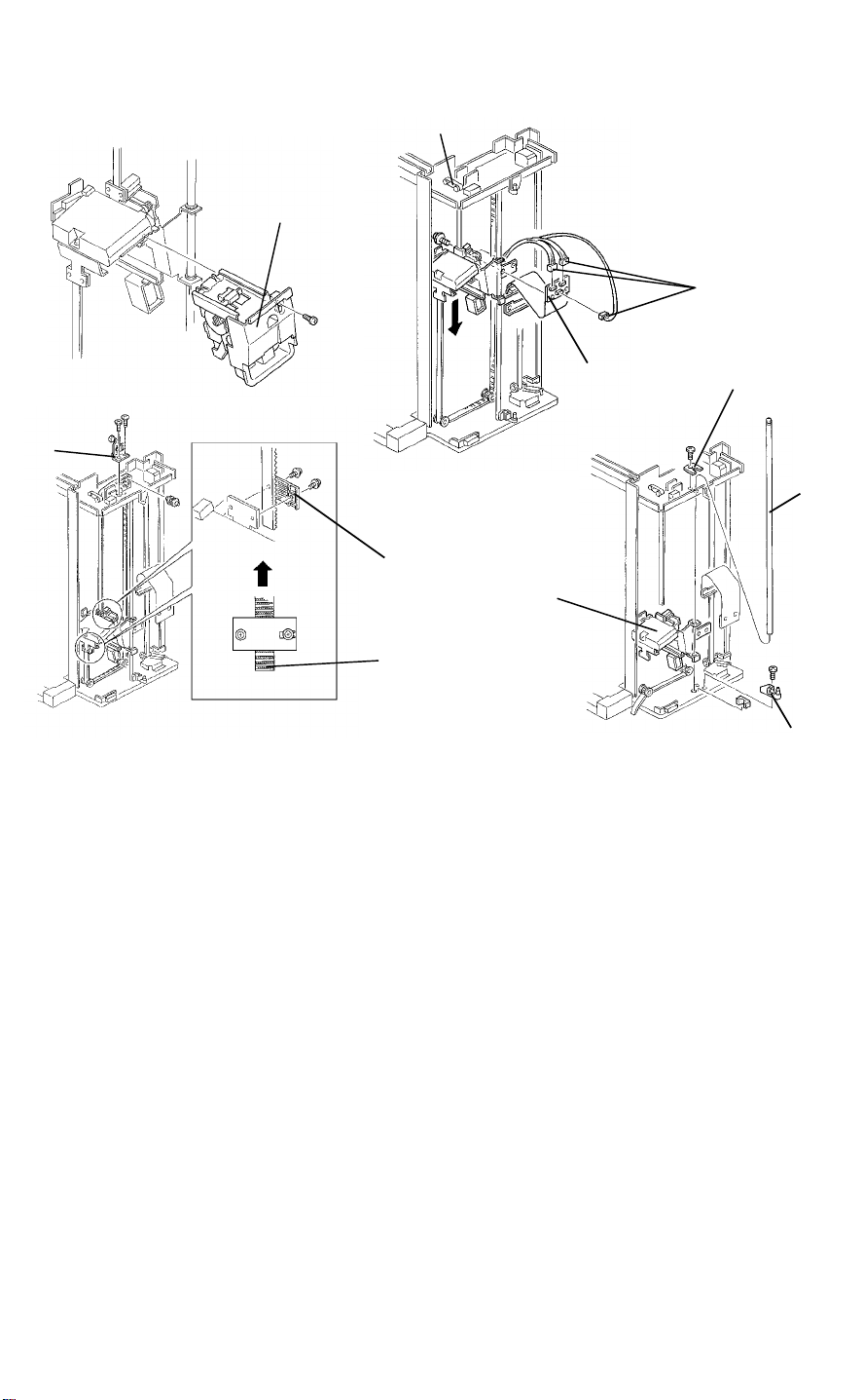
5.5 STAPLE ELEVATOR UNIT REMOVAL
[A]
[D]
[C]
[B]
[I]
[E]
[G]
[K]
[F]
1. Remove the upper cover, the front door, the right front cover.
2. Remove the staple unit [A] (1 screw).
3. Remove the two screws fixing the flat cable [B] and disconnect the three
connectors [C].
4. Lower the staple elevator unit by turning the timing belt [D]of the staple
unit positioning motor manually until it reaches to the lower limit.
[J]
[H]
5. Remove the idle pulley [E] (2 screws).
6. Count the number of the timing belt [F] pitches that stickout of the fixing
plates [G]. Then remove the two fixing plates (2 screws each).
7. Remove the front door hinge [H] (1 screw) and the elevator guide bar
fixing bracket [I] (1 screw).
8. Slide out the elevator guide bar [J] and remove the elevator unit [K].
NOTE: When reassembling the machine, fix the belt with the fixing plate
as it was confirmed in step 6.
42
Page 44
6 March 1992 REPLACEMENT AND ADJUSTMENT
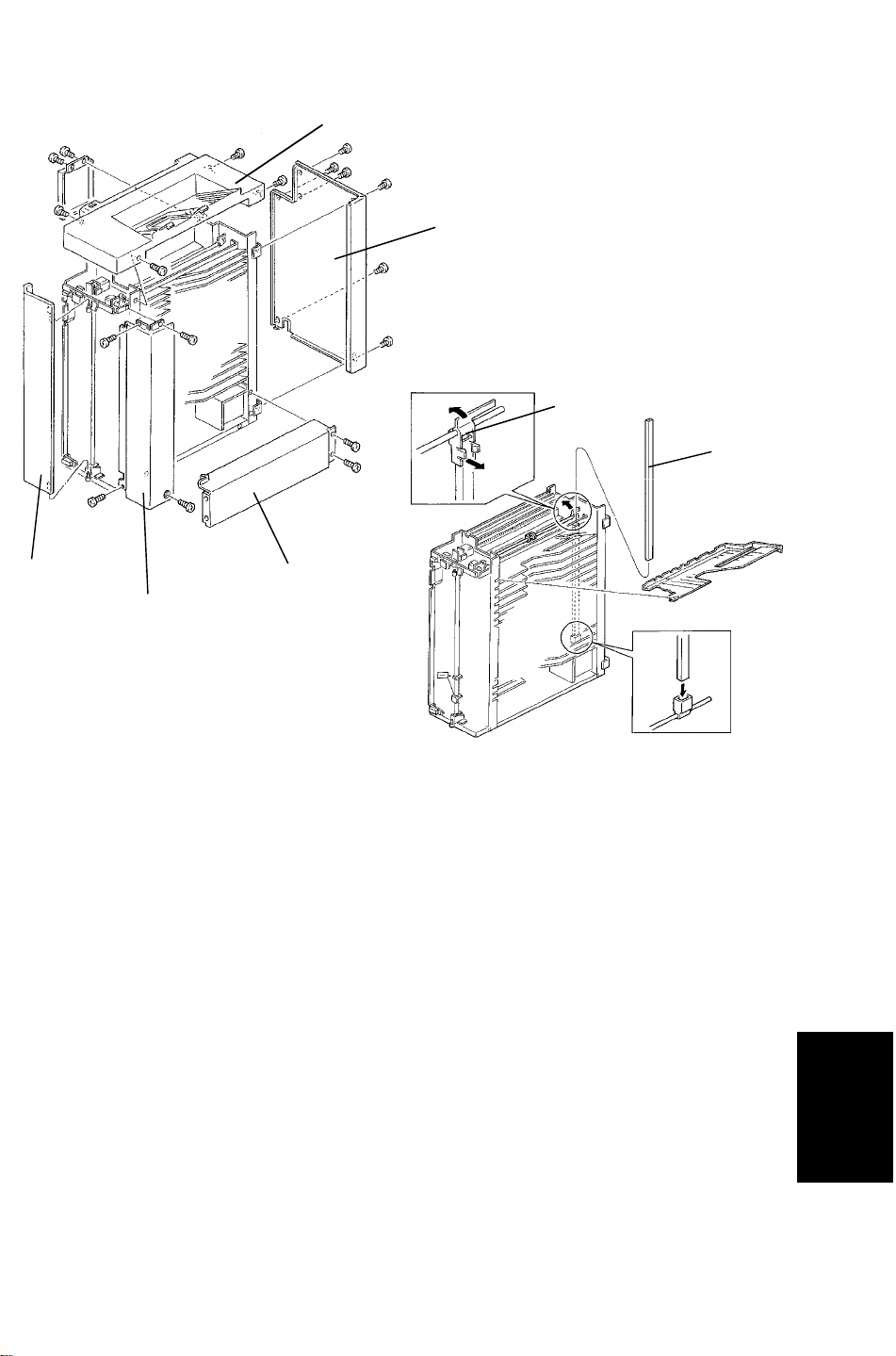
5.6 BIN REMOVAL
[A]
[B]
[G]
[F]
[C]
[E]
[D]
1. Remove the upper cover [A], the rear cover [B], the front door [C] the right
front cover [D], and the lower right cover [E].
2. Remove off the side bar [F] from the side bar holder [G] and remove it.
3. Remove the appropriate bin.
43
Sorter Stapler
Page 45
REPLACEMENT AND ADJUSTMENT 6 March 1992
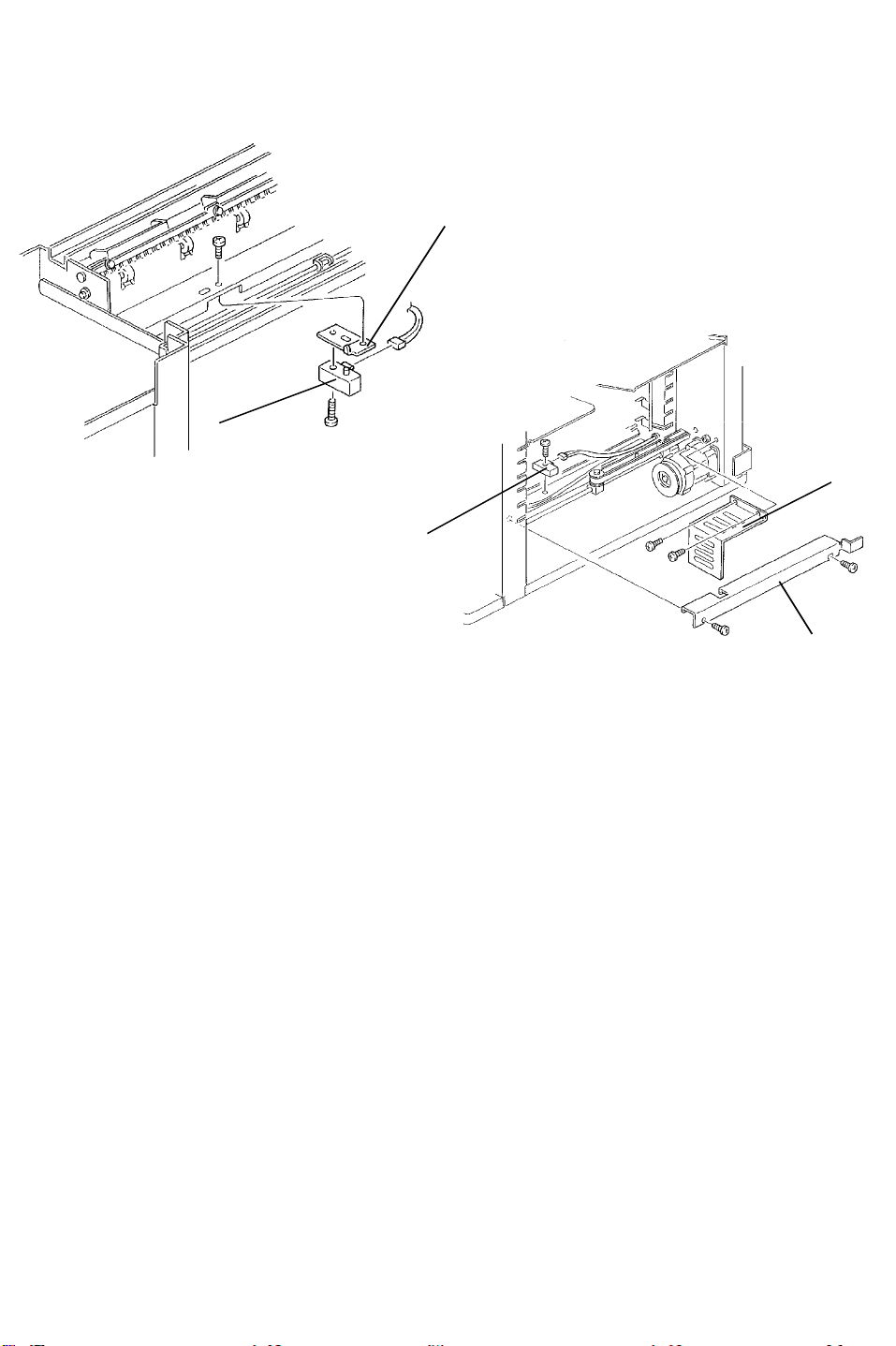
5.7 BIN/JAM SENSOR REMOVAL
[A]
[B]
[E]
[C]
Upper Bin/Jam Sensor
1. Remove the upper cover (4 screws).
2. Remove the bin/jam sensor bracket [A] (1 screw).
3. Replace the upper bin/jam sensor [B] (1 screw).
4. Adjust the sensor sensitivity by turning VR100 and 101 on the main board.
Lower Bin/Jam Sensor
1. Remove the motor cover [C] (2 screws) and the harness cover [D] (2
screws).
2. Remove the bottom 5 bins.
3. Replace the lower bin/jam sensor [E] (1 screw).
4. Adjust the sensor sensitivity by turning VR100 and 101 on the main board.
[D]
44
Page 46
6 March 1992 REPLACEMENT AND ADJUSTMENT
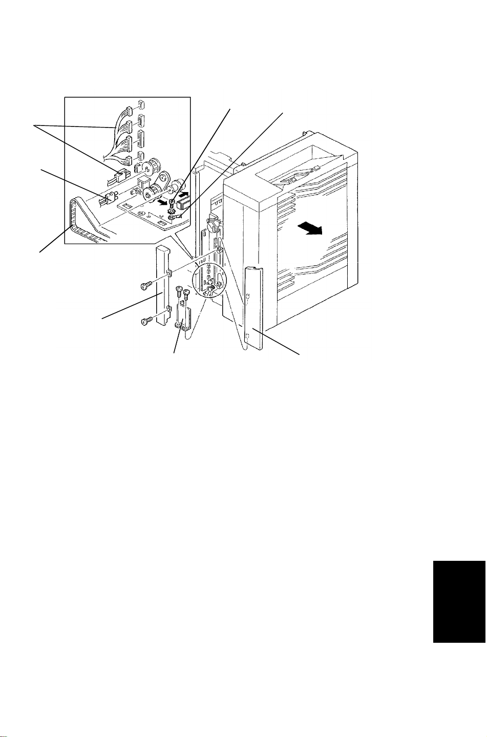
5.8 SORTER DETACHMENT
[D]
[E]
[G]
[A]
[C]
[F]
[H]
[B]
1. Remove the front cover [A] of the diagonal transport unit (2 screws) and
remove the front door [B].
2. Remove the harness cover [C] (2 screws).
3. Disconnect the 5 connectors [D], the fiber optic cable [E] and remove the
screw [F] fixing the ground line.
4. Take the timing belt [G] off the pulleys.
5. Press the lock lever [H] to the allow direction and detach the sorter from
the copier.
Sorter Stapler
45
 Loading...