

Ricoh SR5060, SR5050 Field Service Manual

Booklet Finisher SR5060
Finisher SR5050
Machine Code: D734/D735
Field Service Manual
V1.1
May 2015

Revision History
This is the Revision History for the Booklet Finisher SR5050/SR5060 service manual.
Version Date Changes
Text, Illustrations. In procedures the order of the text and
Ver. 1.1 31 Mar 2015
illustrations has been reversed. For each step, the text description
(action) is followed by the relevant illustration. The callouts [A], [B],
[C] in text refer to the illustration below, not above.
1

Symbols, Abbreviations and Trademarks
Conventions
Symbol What it means
Binding screw (shoulder hexagonal head)
Binding screw (round flathead)
Black screw (heavy, fusing unit, TCRU)
Bushing
C-ring
Clip
Connector
E-ring
FFC (Flat Film Connector)
FFC (Flat Film Connector)
FFC (Flat Film Connector)
Gear
Harness clamp
Harness clamp: metal: fusing unit
Hook (or tab release: sensors)
Knob screw (black)
Knob screw (sliver)
Pivot screw
Screw: most common: silver
Shoulder screw
2
Symbol What it means
Shoulder screw (black)
Spring
Standoff
Stud screw
Tapping screw (for plastic)
Timing belt
Washer
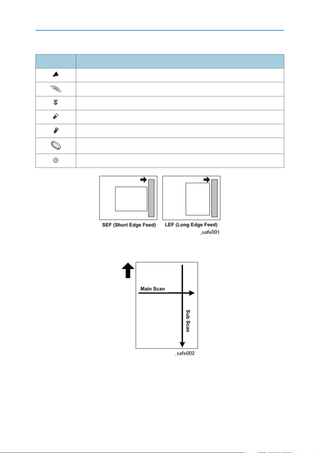
The notations "SEF" and "LEF" describe the direction of paper feed. The arrows indicate the direction of
paper feed.
In this manual "Main Scan" means "Horizontal" and "Sub Scan" means "Vertical", both relative to the
direction of paper feed.
3
Warnings, Cautions, Notes
In this manual, the following important symbols and notations are used.
• A Warning indicates a potentially hazardous situation. Failure to obey a Warning could result in
death or serious injury.
• A Caution indicates a potentially hazardous situation. Failure to obey a Caution could result in
minor or moderate injury or damage to the machine or other property.
• Obey these guidelines to avoid problems such as misfeeds, damage to originals, loss of valuable
data and to prevent damage to the machine.
• This information provides tips and advice about how to best service the machine.
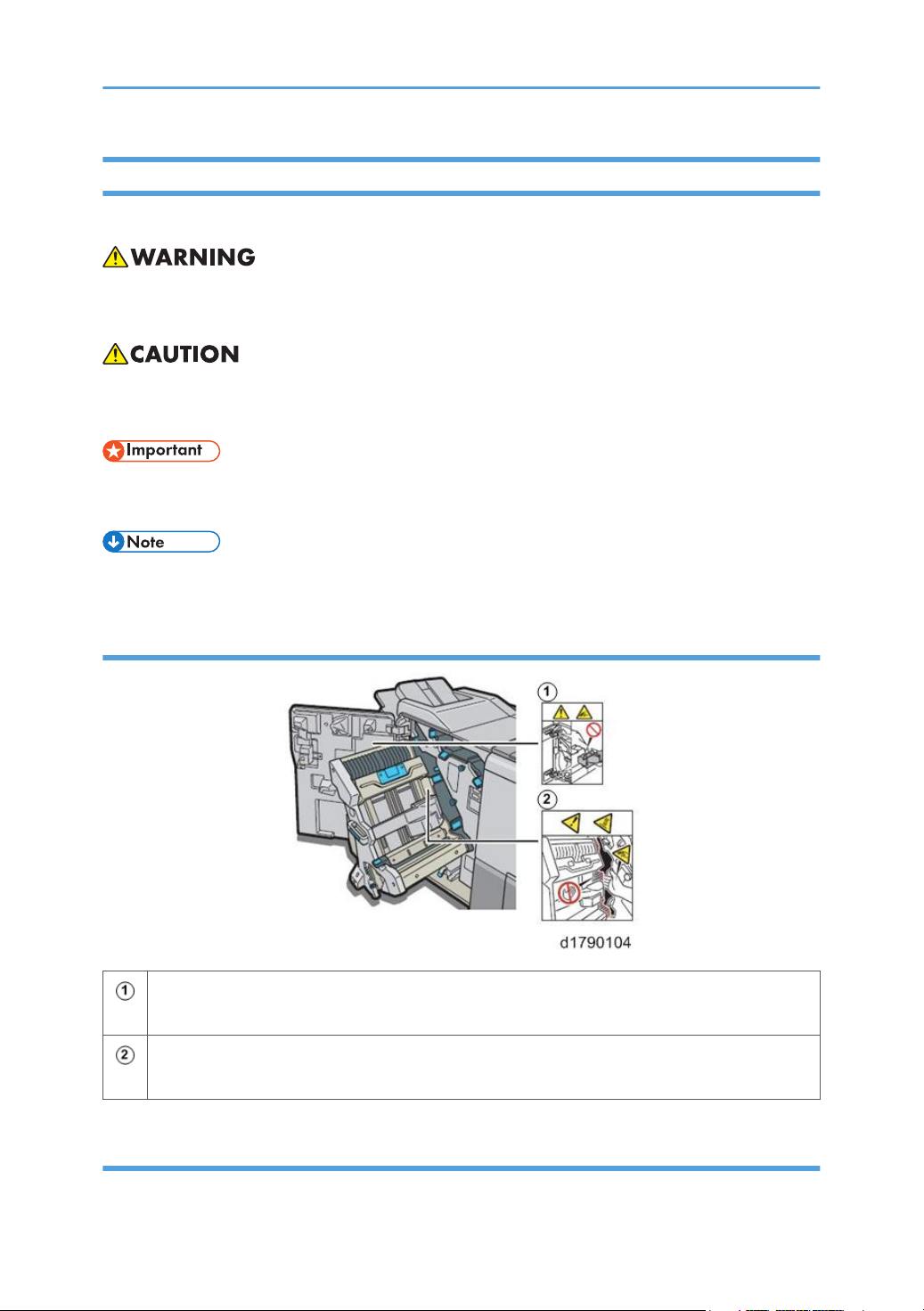
Finisher SR5050
To avoid injury, keep your hands clear of the hinges when opening and closing the finisher
door.
To avoid injury, avoid the indicated parts that become hot during operation and locations
where you could pinch your hand or fingers.
Booklet Finisher SR5060
Front
4
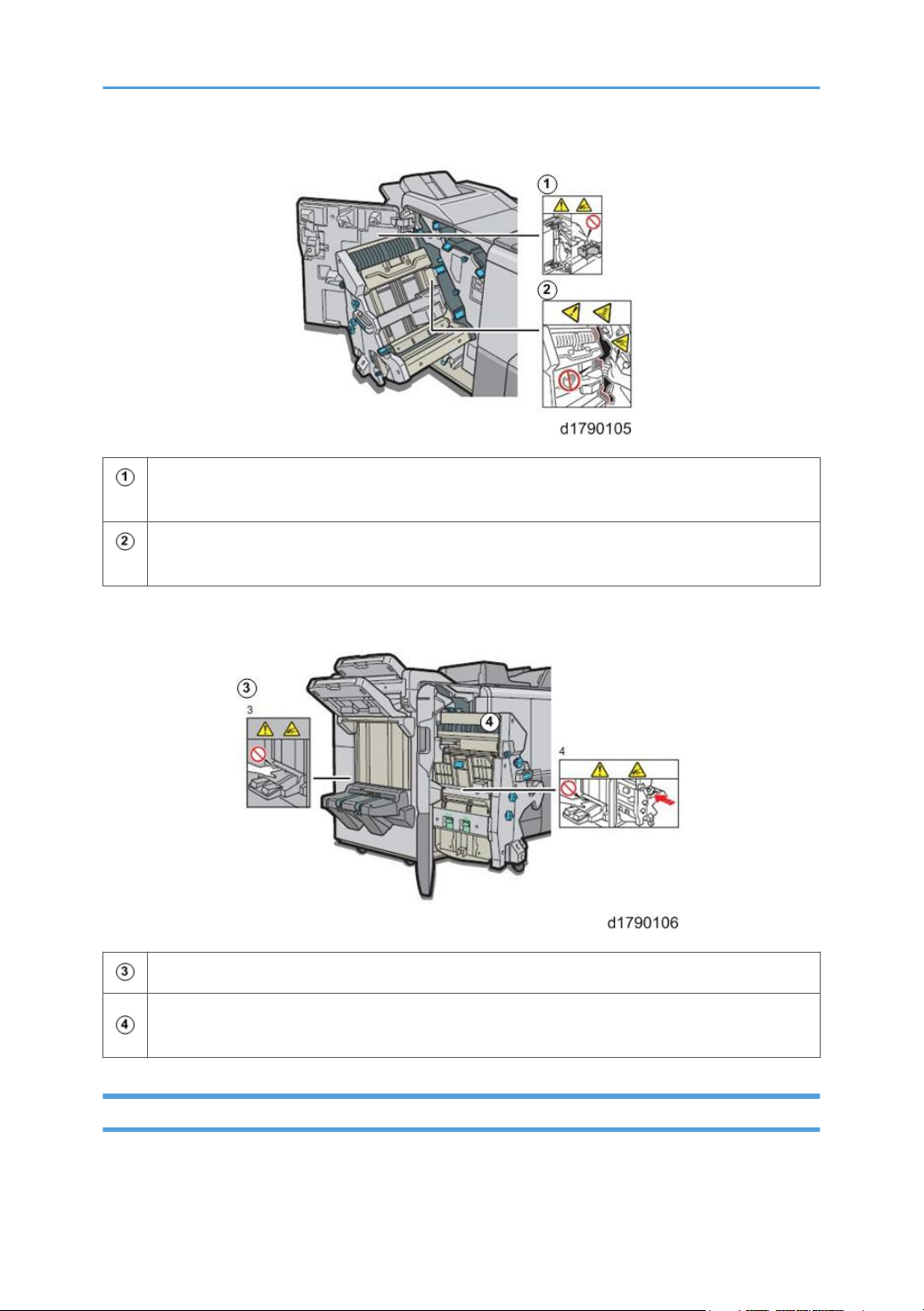
To avoid injury, keep your hands clear of the hinges when opening and closing the finisher
door.
To avoid injury, avoid the indicated parts that become hot during operation and locations
where you could pinch your hand or fingers.
Left Side
To avoid injury, never touch the booklet tray during operation.
To avoid injury, never touch the booklet tray when removing a paper jam, or when pulling out
or pushing in the stacker/stapler unit.
Commonly Used Terms and Abbreviations
Here is a list of commonly used terms and abbreviations that are used throughout the Field Service
Manual and Appendices.
5

Terms Meaning
(ccw) Counter-clockwise rotation of a drum, roller, gear, etc.
(cw) Clockwise rotation of a drum, roller, gear, etc.
BF Booklet Finisher SR5060 (D734)*
1
BW Black and white (monochrome) copying or printing
Bank Paper Bank (1st, 2nd, 3rd Tray of the main machine)
CIT Cover Interposer Tray CI5030 (D738)*
1
CIT-PB Cover Interposer Tray for Perfect Binder Type S1 (D736-2)*
FIN Finisher SR5050 (D735) (corner staple only, no booklets)*
ITB Image Transfer Belt
JG Junction Gate
LCIT Large Capacity Input Tray.
LCIT RT5080 (D732) or LCIT RT5070 (D733)*
1
LD Laser Diode (Laser Unit)
LE Leading Edge
LSDB Laser Synchronization Detection Board (Laser Unit)
MFU Multi Folding Unit FD5020 (D740)*
1
1
1
PCDU Photoconductor Development Unit
PB Perfect Binder GB5010 (D736)*
1
PFU Paper Feed Unit (Tray 1, Tray 2, Tray 3)
PTB Paper Transport Belt (between PTR and fusing unit)
PTR Paper Transfer Roller
RB Ring Binder RB5020 (D737)
TCRU Trained Customer Replacement Units
TE Trailing Edge
6

Terms Meaning
TM/P ID sensor. "ID sensor" is used in this manual. However, you may see "TM/P" in the SP
codes on the operation panel.
TPU Transit Path Unit for Perfect Binder Type S1 (D736)*
TRM Trimmer Unit 5040 (D520)*
1
1
VTU Vertical Transport Unit
*1Optional peripheral devices.
Trademarks
• Microsoft®, and Windows® are registered trademarks of Microsoft Corporation in the United
States and /or other countries.
• PostScript® is a registered trademark of Adobe Systems, Incorporated.
• PCL® is a registered trademark of Hewlett-Packard Company.
• Ethernet® is a registered trademark of Xerox Corporation.
• PowerPC® is a registered trademark of International Business Machines Corporation.
• Other product names used herein are for identification purposes only and may be trademarks of
their respective companies. We disclaim any and all rights involved with those marks.
7

TABLE OF CONTENTS
Revision History...................................................................................................................................................1
Symbols, Abbreviations and Trademarks ........................................................................................................2
Conventions.................................................................................................................................................... 2
Warnings, Cautions, Notes...........................................................................................................................4
Finisher SR5050.................................................................................................................................... 4
Booklet Finisher SR5060...................................................................................................................... 4
Commonly Used Terms and Abbreviations..................................................................................................5
Trademarks..................................................................................................................................................... 7
1. Replacement and Adjustment
Common Procedures........................................................................................................................................13
Overview...................................................................................................................................................... 13
Covers...........................................................................................................................................................15
Rear Upper Cover...............................................................................................................................15
Rear Lower Cover............................................................................................................................... 16
Lower Inner Cover: Rb10, Rb11....................................................................................................... 17
Center Inner Cover: Rb14, Rb16...................................................................................................... 18
Upper Inner Cover: Rb2, Rb8............................................................................................................19
Front Door............................................................................................................................................19
Proof Tray.............................................................................................................................................20
Corner Strip Cover..............................................................................................................................20
Top Right Cover...................................................................................................................................21
Top Rear Cover................................................................................................................................... 22
Shift Tray Jogger Unit..........................................................................................................................22
Left Upper Cover................................................................................................................................. 23
Upper, Lower Right Panels................................................................................................................. 24
Shift Tray.............................................................................................................................................. 25
Booklet Tray.........................................................................................................................................26
Booklet Unit.................................................................................................................................................. 28
Booklet Stapler.................................................................................................................................... 28
Booklet Unit Removal..........................................................................................................................29
Handling and Moving the Booklet Unit.............................................................................................32
End Fence..................................................................................................................................................... 33
Exit Roller Cover..................................................................................................................................33
8

Shift Tray.............................................................................................................................................. 34
Shift Tray Base.....................................................................................................................................35
Left Lower Cover..................................................................................................................................38
End Fence............................................................................................................................................ 39
Drag Roller Unit............................................................................................................................................41
Horizontal Paper Feed.....................................................................................................................................45
Entrance........................................................................................................................................................45
Entrance Roller Motor(........................................................................................................................45
Entrance Sensor...................................................................................................................................49
Registration...................................................................................................................................................50
Registration Motor...............................................................................................................................50
Horizontal Transport Motor............................................................................................................... 52
Proof Tray..........................................................................................................................................................54
Proof Tray Motors........................................................................................................................................ 54
Proof Tray JG Motor........................................................................................................................... 54
Proof Tray Vertical Transport Motor.................................................................................................. 55
Proof Tray Exit Motor..........................................................................................................................57
Proof Tray Sensors....................................................................................................................................... 58
Proof Tray JG HP Sensor.................................................................................................................... 58
Proof Tray Exit Sensor, Proof Tray Full Sensor..................................................................................60
Shift Tray........................................................................................................................................................... 63
Shift Tray Side-to-Side Movement..............................................................................................................63
Shift Motor........................................................................................................................................... 63
Shift Tray HP Sensors (Front, Rear)....................................................................................................64
Shift Tray Exit................................................................................................................................................65
Shift Tray Exit Motor............................................................................................................................65
Shift Tray Exit Sensors (Long and Short)............................................................................................66
Drag Roller Motors, Sensors.......................................................................................................................70
Preparation.......................................................................................................................................... 70
Drag Roller Motor...............................................................................................................................71
Drag Roller Drive Motor.....................................................................................................................72
Drag Roller HP Sensor........................................................................................................................ 73
Shift Tray Jogger Unit...................................................................................................................................74
9

Shift Jogger Motor.............................................................................................................................. 74
Shift Tray Jogger Fence HP Sensor....................................................................................................76
Shift Jogger Retraction Motor............................................................................................................ 76
Shift Jogger Fence Retract HP Sensor................................................................................................78
Shift Tray Operation.................................................................................................................................... 78
Shift Tray Lift Motor............................................................................................................................. 78
Paper Height Sensors 1, 2, 3 (Shift, Staple, Z-Fold)....................................................................... 80
Paper Height Sensor (TE), Shift Tray Upper Limit Switch................................................................. 81
Shift Tray Full Sensors 1, 2, 3, 4 (500).............................................................................................85
Pre-Stacker........................................................................................................................................................88
Pre-Stack Motors..........................................................................................................................................88
Pre-Stack Motor.................................................................................................................................. 88
Pre-Stack Release Motor, Pre-Stack Roller HP Sensor.....................................................................91
Corner Stapler Unit.......................................................................................................................................... 97
Corner Stapler Unit Entrance...................................................................................................................... 97
Stapler JG Motor.................................................................................................................................97
Stapler JG HP Sensor..........................................................................................................................98
Stapling Tray Entrance Sensor........................................................................................................... 99
Stapling Tray Entrance Motor..........................................................................................................100
Corner Stapler Side-to-Side Jogging.......................................................................................................102
Front Jogger Fence Motor................................................................................................................102
Jogger Fence HP Sensor (Front)...................................................................................................... 104
Rear Jogger Fence Motor................................................................................................................ 104
Jogger Fence HP Sensor (Rear).......................................................................................................107
Corner Stapling Bottom, Top Jogging..................................................................................................... 108
Positioning Roller Rotation Motor....................................................................................................108
Positioning Roller Motor...................................................................................................................109
Positioning Roller HP Sensor............................................................................................................110
Leading Edge Stopper HP Sensor, Staple Tray Paper Sensor......................................................111
Top Fence HP Sensor....................................................................................................................... 112
Corner Stapling......................................................................................................................................... 114
Corner Stapler.................................................................................................................................. 114
Corner Stapler Movement Motor....................................................................................................116
10

Stapler Rotation Motor.....................................................................................................................118
Staple Trimmings Hopper Full, Hopper Set Sensor....................................................................... 119
Stapler Movement Sensors..............................................................................................................121
Corner Stapled Stack Feed Out...............................................................................................................124
Stack Transport Motor......................................................................................................................124
Stack Transport Unit HP Sensor.......................................................................................................125
Stack Feed-Out Belt Motor.............................................................................................................. 126
Stack Feed-Out Belt HP Sensor....................................................................................................... 128
Stack Junction Gate Motor.............................................................................................................. 129
Stack JG HP Sensor..........................................................................................................................130
Corner Stapled Stack Exit to Shift Tray....................................................................................................131
Exit Guide Motor.............................................................................................................................. 131
Exit Guide HP Sensor....................................................................................................................... 134
Booklet Unit.................................................................................................................................................... 135
Booklet Stapler.......................................................................................................................................... 135
Booklet Unit Transport, Entrance..............................................................................................................136
Fold Unit Entrance Sensor................................................................................................................136
Booklet Side-to-Side Jogging...................................................................................................................136
Booklet Stapler Side Fence Motor.................................................................................................. 136
Booklet Stapler Side Fence HP Sensor (Front)............................................................................... 138
Booklet Stapler Jogger HP Sensor (Rear).......................................................................................138
Booklet Bottom, Top Jogging................................................................................................................... 139
Booklet Stapler Bottom Fence Motor..............................................................................................139
Booklet Stapler Bottom Fence HP Sensor....................................................................................... 140
Booklet Stapler Top Fence Motor................................................................................................... 142
Booklet Top Fence HP Sensor..........................................................................................................143
Booklet Press for Stapling......................................................................................................................... 143
Booklet Stapler Clamp Roller Motor, Booklet Stapler Exit Sensor............................................... 143
Booklet Stapler Clamp Roller HP Sensor........................................................................................151
Booklet Folding..........................................................................................................................................153
Fold Roller Motor..............................................................................................................................153
Fold Plate Cam HP Sensor............................................................................................................... 154
Fold Plate HP Sensor........................................................................................................................ 155
11

Booklet Exit.................................................................................................................................................156
Fold Roller Motor..............................................................................................................................156
Boards............................................................................................................................................................ 159
Main Board................................................................................................................................................159
Punch Unit PCB.......................................................................................................................................... 161
Shift Tray Jogger Unit PCB........................................................................................................................161
PSU............................................................................................................................................................. 162
Switches..........................................................................................................................................................166
Front Door Switch......................................................................................................................................166
Emergency Shift Tray Stop Switch............................................................................................................167
Rollers and Brushes........................................................................................................................................168
Rollers.........................................................................................................................................................168
Drag Roller........................................................................................................................................ 168
Positioning Roller...............................................................................................................................168
Alignment Brush Roller..................................................................................................................... 169
Discharge Brushes..................................................................................................................................... 171
Shift Tray Exit.....................................................................................................................................171
Corner Stapler Entrance...................................................................................................................172
Booklet Unit Exit................................................................................................................................ 173
Special Adjustments.......................................................................................................................................174
Horizontal Skew Adjustment.................................................................................................................... 174
[A] Adjustment: Rear Fence Low......................................................................................................175
[B] Adjustment: Front Fence Low......................................................................................................176
Vertical Skew Adjustment..........................................................................................................................177
Base Fence Replacement..........................................................................................................................178
12
1. Replacement and Adjustment
Common Procedures
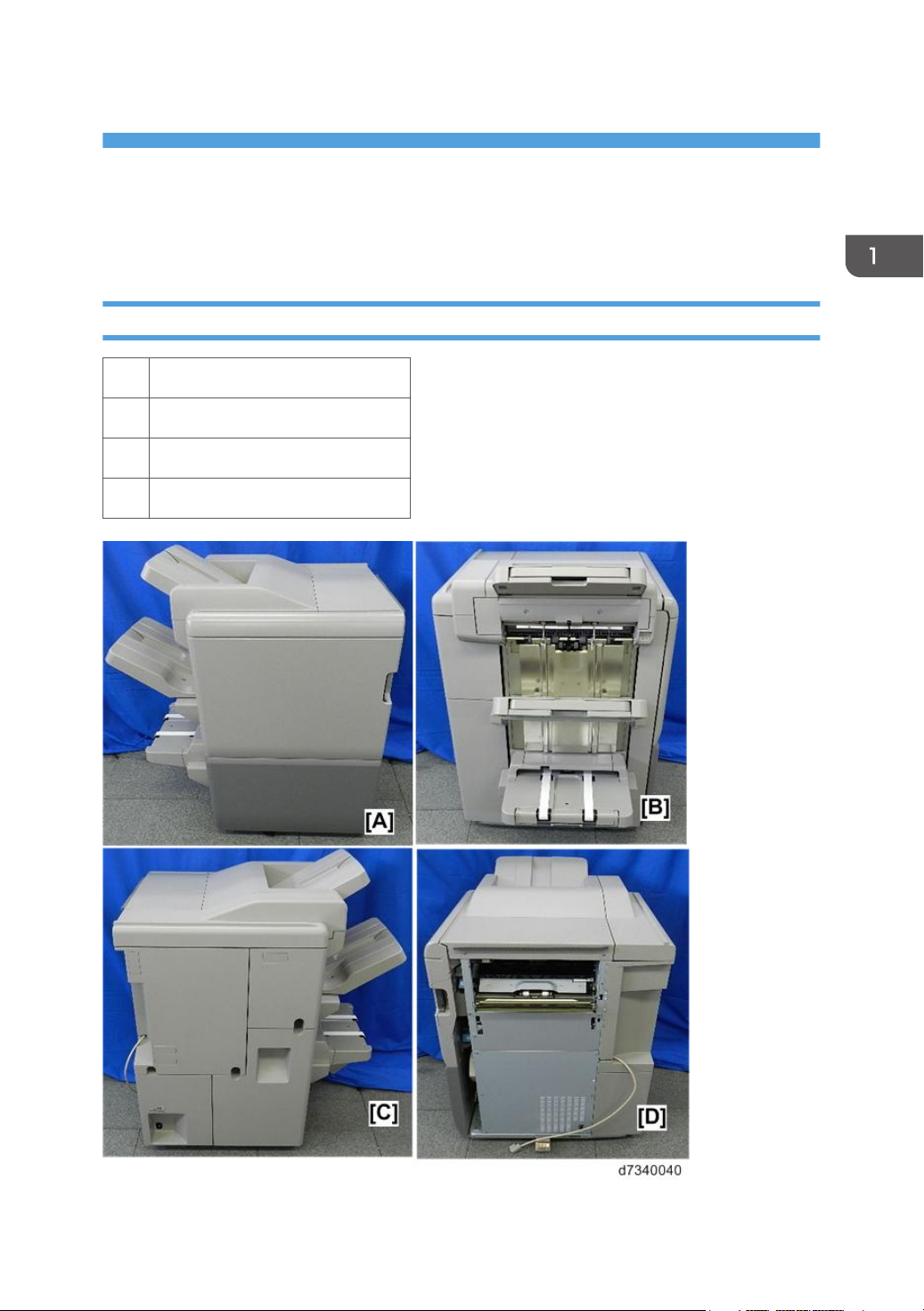
Overview
[A] Front
[B] Left
[C] Rear
[D] Right
13
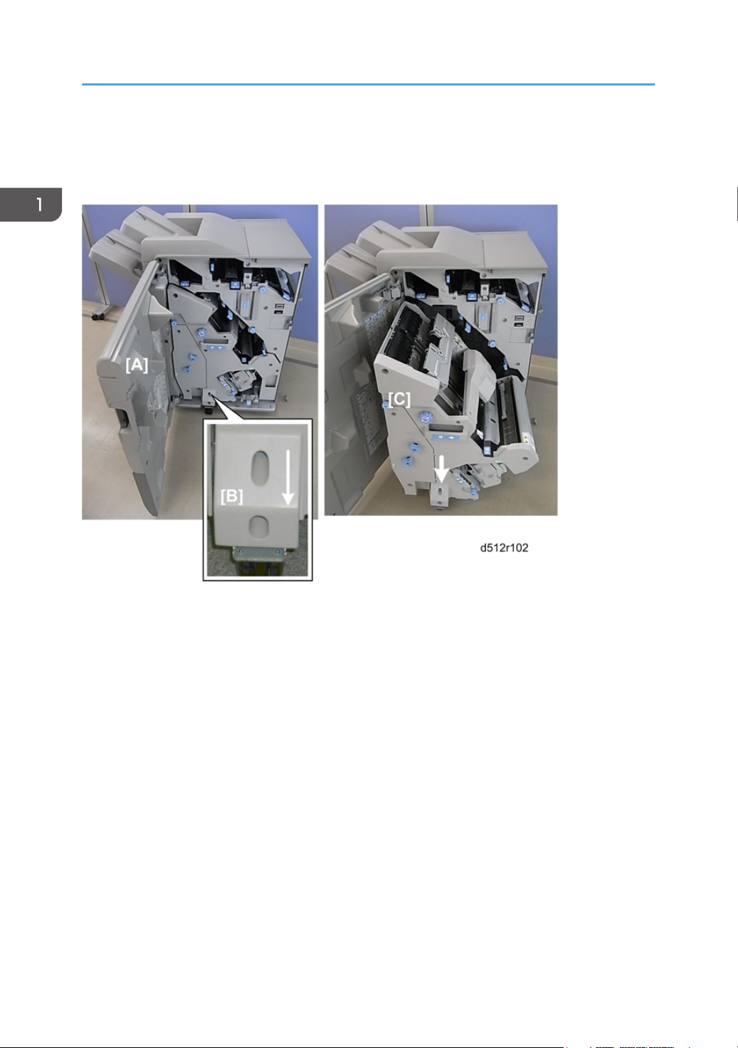
1. Replacement and Adjustment
[A] Open the front door.
[B] Adjustable caster
[C] Pull the stack/stapler unit out (pull handle Rb12).
14
• Inner covers:
[A] Upper: Rb2, Rb8
[B] Center: Rb14, Rb16
[C] Lower Rb10, Rb11

Common Procedures
Covers
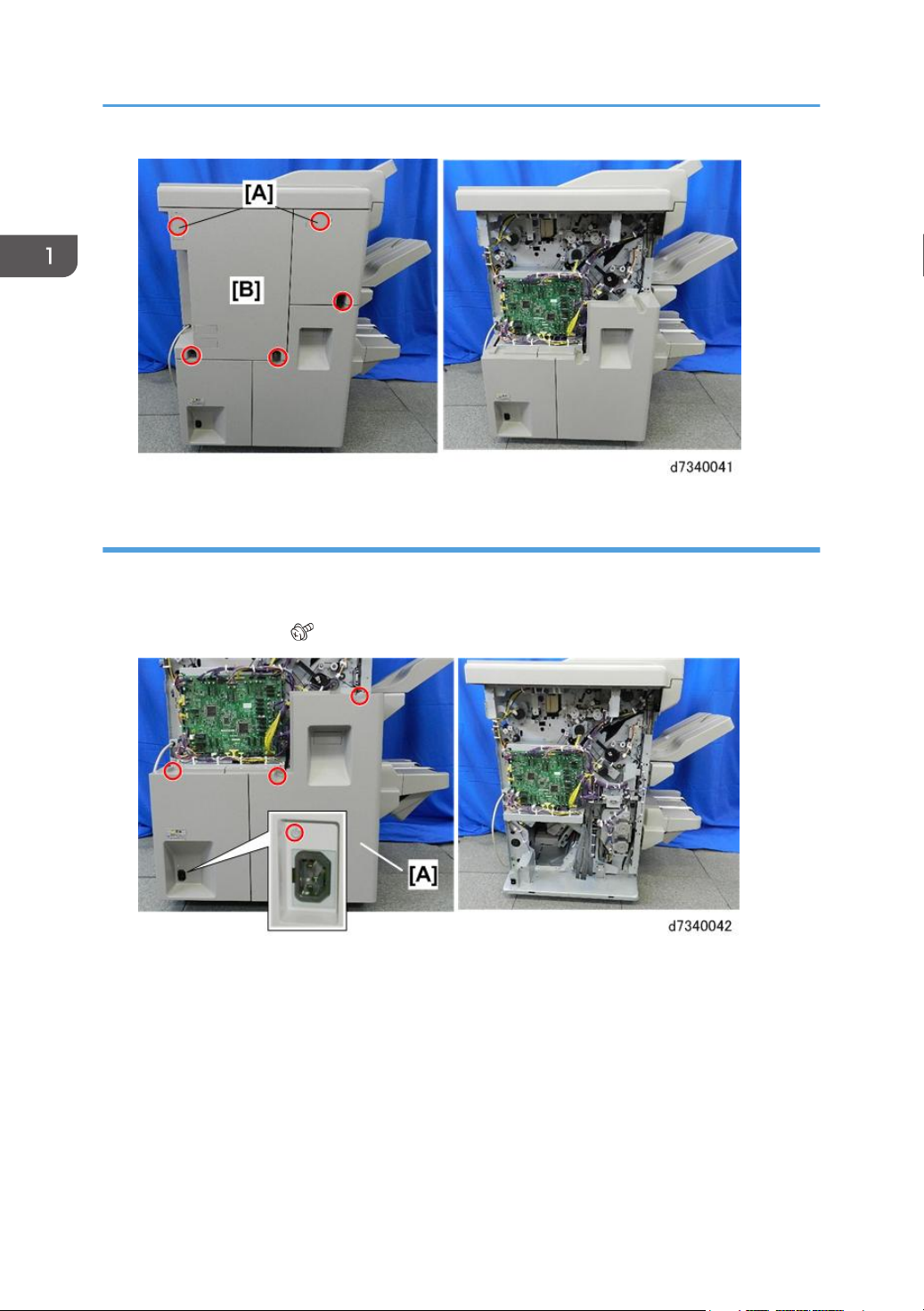
Rear Upper Cover
1. Screw covers [A] (hooks)
2. Rear upper cover [B] ( x5)
• The rear upper cover must be removed before the rear lower cover.
15
1. Replacement and Adjustment
Rear Lower Cover
Preparation
• Rear upper cover
1. Rear lower cover [A] ( x4). The screw near the power connection point is difficult to see.
Re-installation
1. Engage both tabs on the bottom of the rear lower cover before fastening the screws.
16
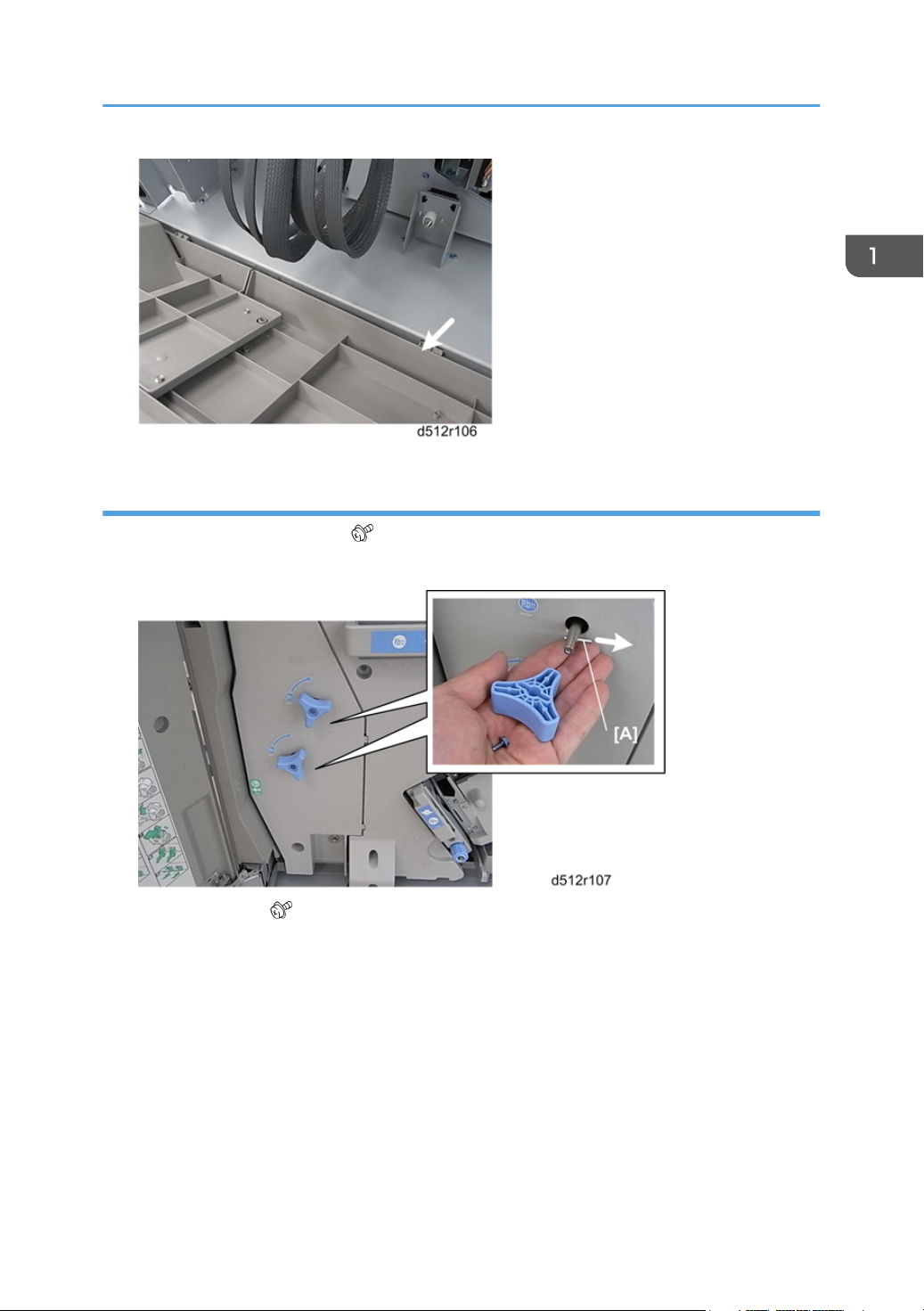
Lower Inner Cover: Rb10, Rb11
1. Remove handles Rb11, Rb12 ( x1 each, Pin x1 each).
2. Make sure that the pins [A] are removed and stored with the screws.
Common Procedures
3. Remove the cover ( x2, Tabs x2).
17
1. Replacement and Adjustment
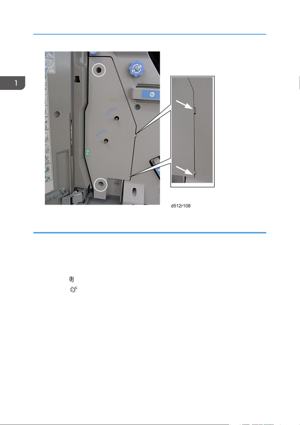
Center Inner Cover: Rb14, Rb16
Preparation
• Lower inner cover
1. Remove:
[A] Rb16
[B] Rb 14 ( x1)
[C] Cover ( x4)
18
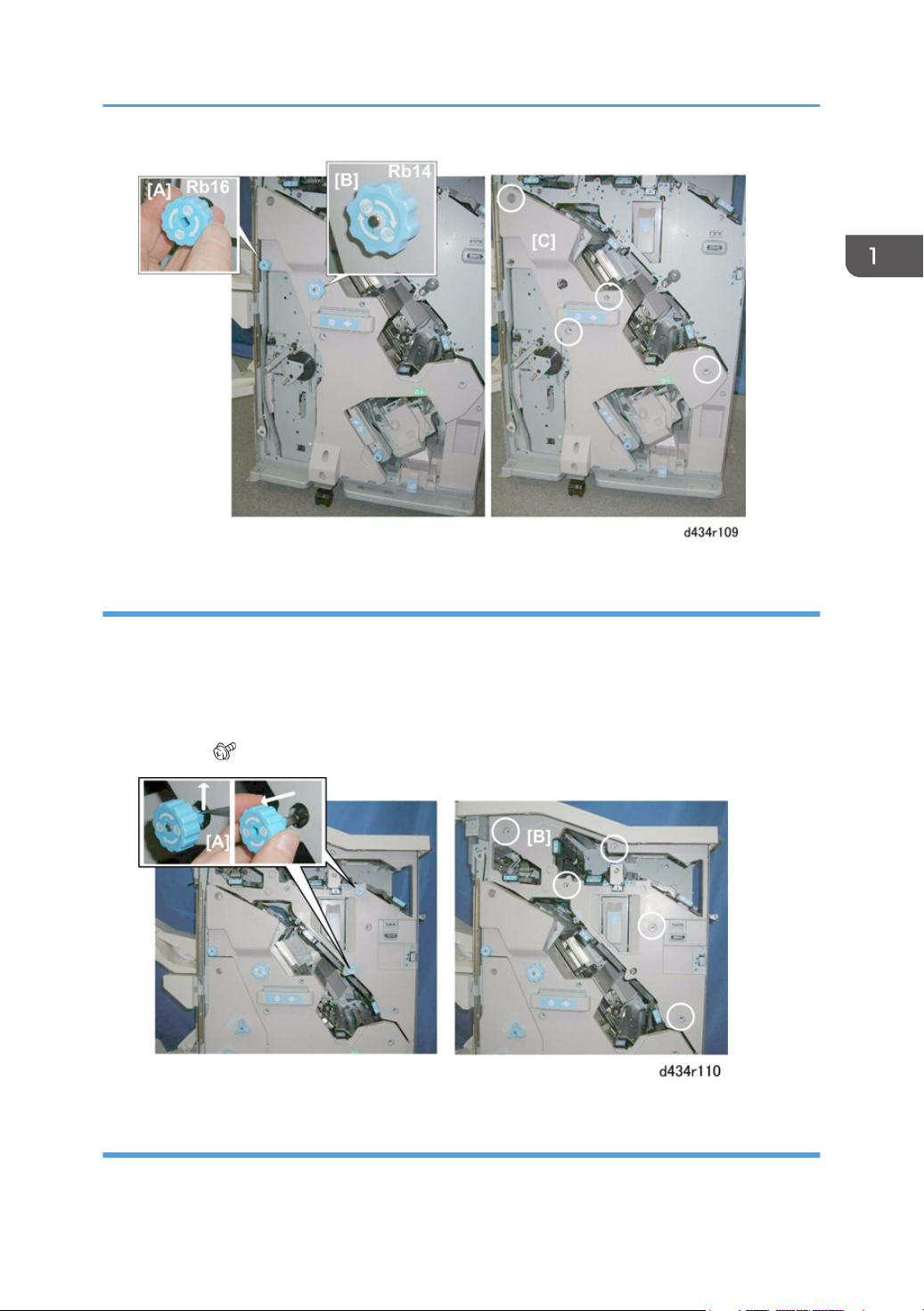
Upper Inner Cover: Rb2, Rb8
Common Procedures
1. Remove:
[A] Rb2, Rb8.
If these tab releases are stiff, use the point of a sharp tool to release these knobs, then pull them off.
Work carefully to avoid breaking the tab releases.
[B] Cover ( x5)
Front Door
1. Open the front door.
19
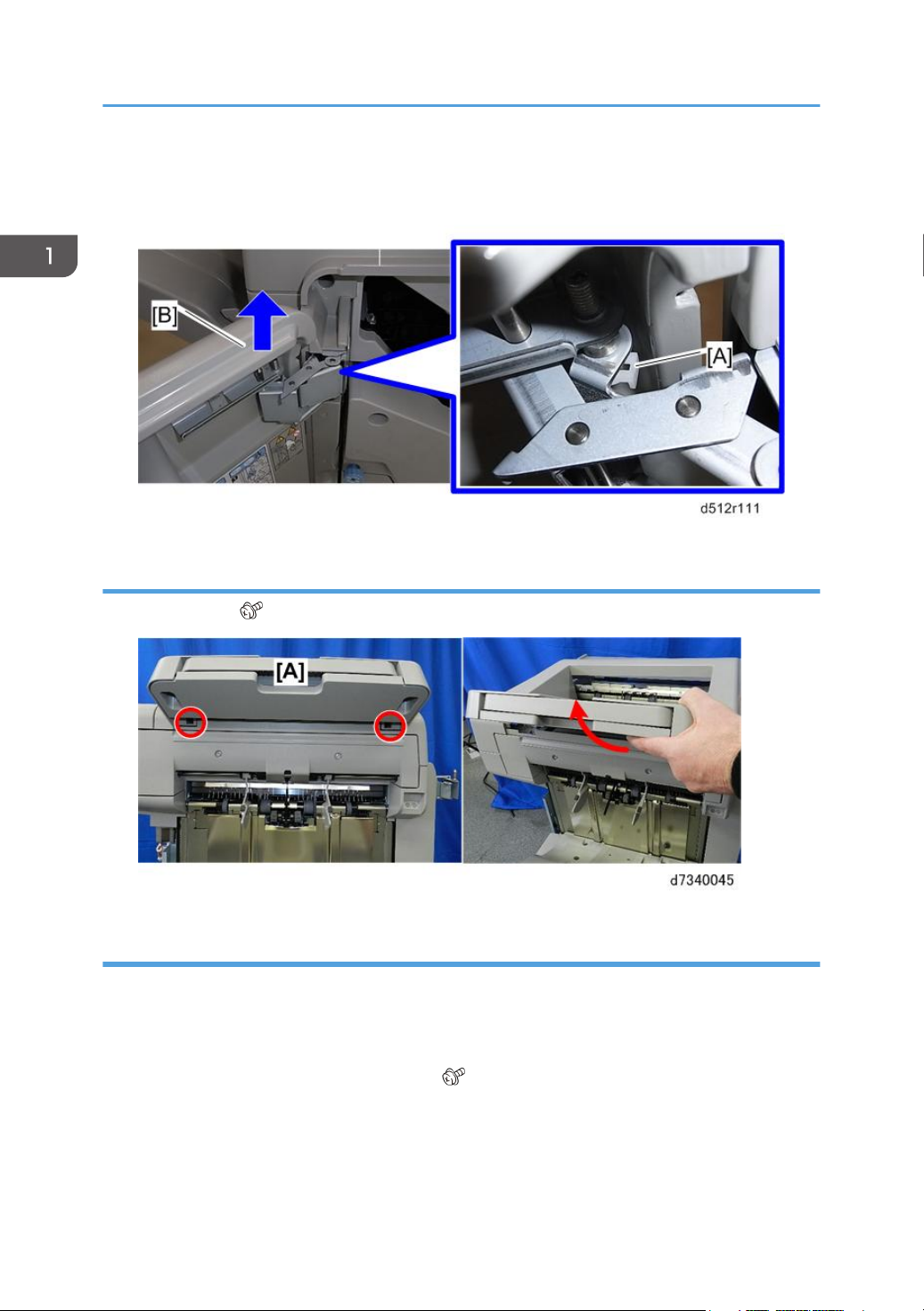
1. Replacement and Adjustment
2. Remove the clip [A].
3. Lift off the door [B] from its bottom post.
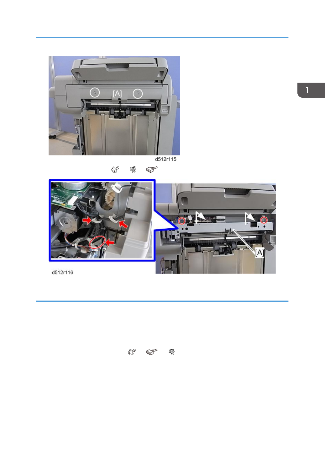
Proof Tray
1. Proof tray [A] ( x2)
Corner Strip Cover
Preparation
• Front door page 19)
• Proof tray page 20)
1. Remove the top and bottom screws [A], [B] ( x2).
2. Disconnect the tabs at the top and bottom.
20
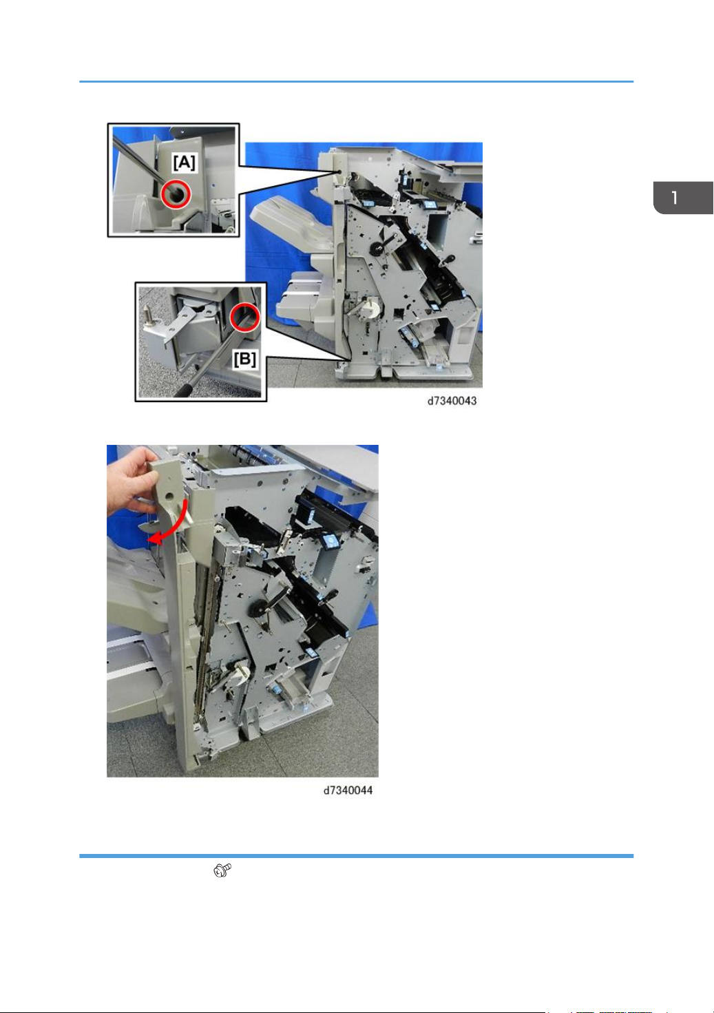
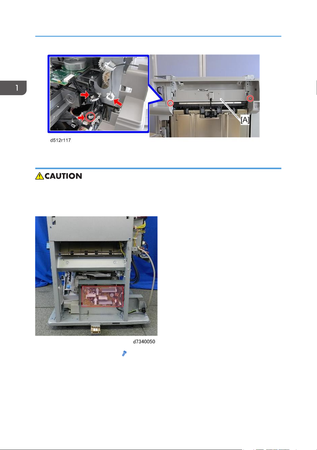
3. Twist the cover away from the corner.
Common Procedures
Top Right Cover
1. Top right cover [A] ( x2)
21
1. Replacement and Adjustment
Top Rear Cover
Preparation
Remove:
• Proof tray (page 20)
• Top right cover (page 21)
• Rear upper cover (page 15)
1. Top rear cover [A] (
Shift Tray Jogger Unit
1. Top rear cover page 22)
2. Remove:
[A] Jogger unit cover ( x2)
x2).
22
3. Lift the jogger unit [A] off ( x2, x2, x1).
Common Procedures
Left Upper Cover
Preparation
Remove:
• Proof tray (page 20
• Shift tray jogger unit (page 22)
1. Remove the left upper cover [B] ( x2, x1, x2).
23
1. Replacement and Adjustment
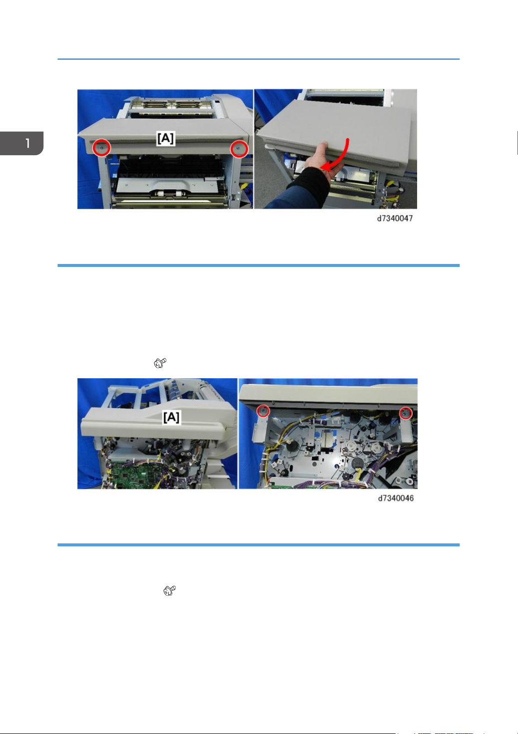
Upper, Lower Right Panels
• The lower right panel covers the PSU, which retains residual voltage after the system is switched off.
• Before removing the right panel for any procedure, switch the machine off and wait 30 min. for the
charge on the PSU to dissipate.
24
1. Remove upper right panel [A] ( x4).
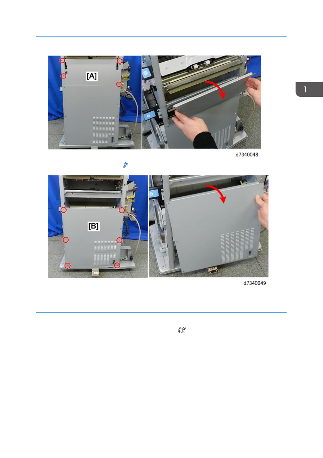
2. Remove lower right panel [B] ( x6).
Common Procedures
Shift Tray
1. While supporting the tray with one hand, pull gear [A] toward you to release the tray.
2. Lower the tray [B] slowly until it stops, then remove it. ( x4)
25
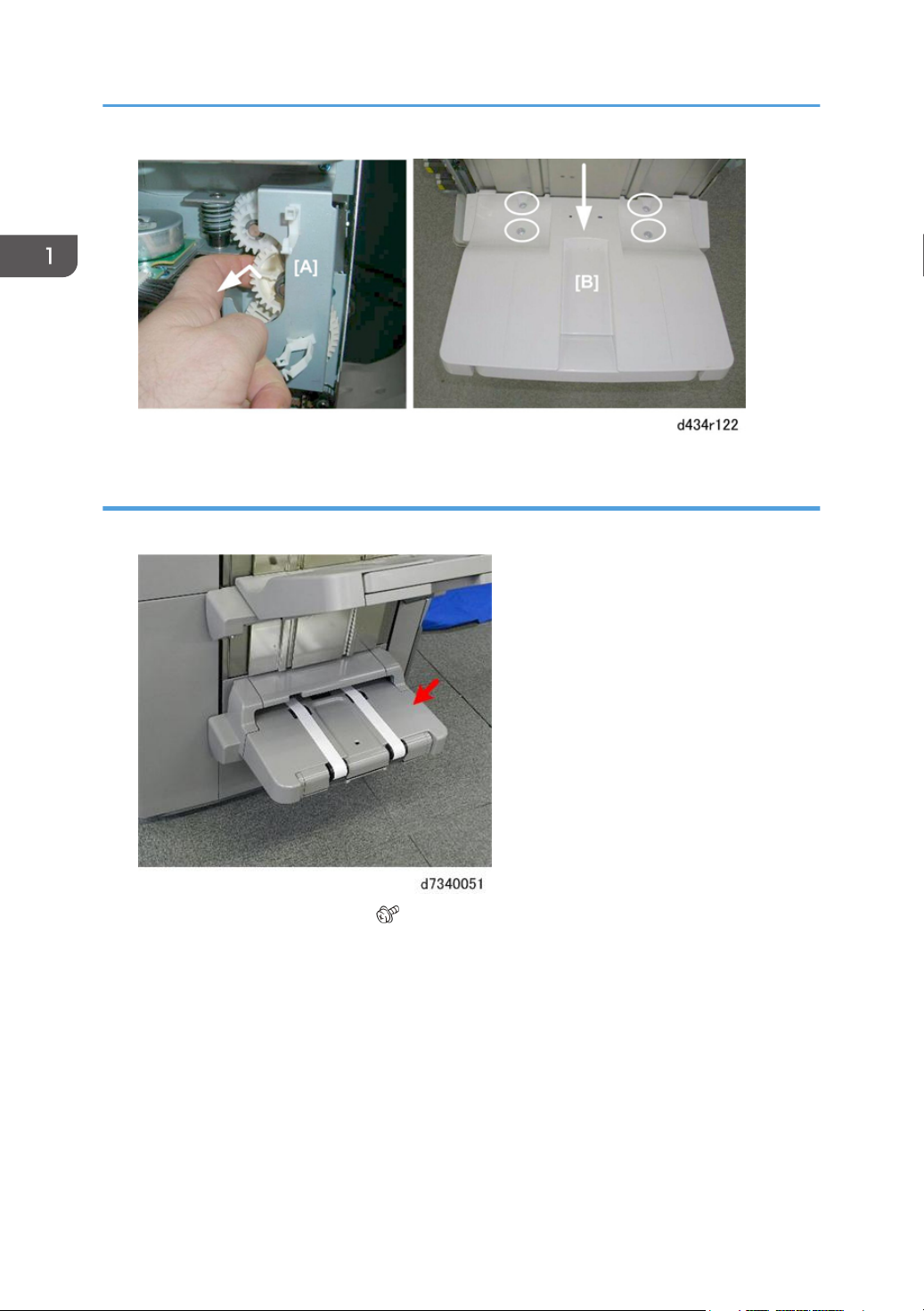
1. Replacement and Adjustment
Booklet Tray
1. The booklet tray is the lower tray.
26
2. At the rear [A] remove rear cover ( x1).
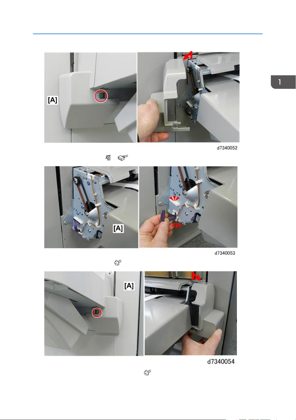
3. At rear [A] disconnect tray ( x1, x1).
Common Procedures
4. At front [A] remove front cover ( x1).
5. Disconnect tray bracket at front [A], rear [B] ( x2).
27
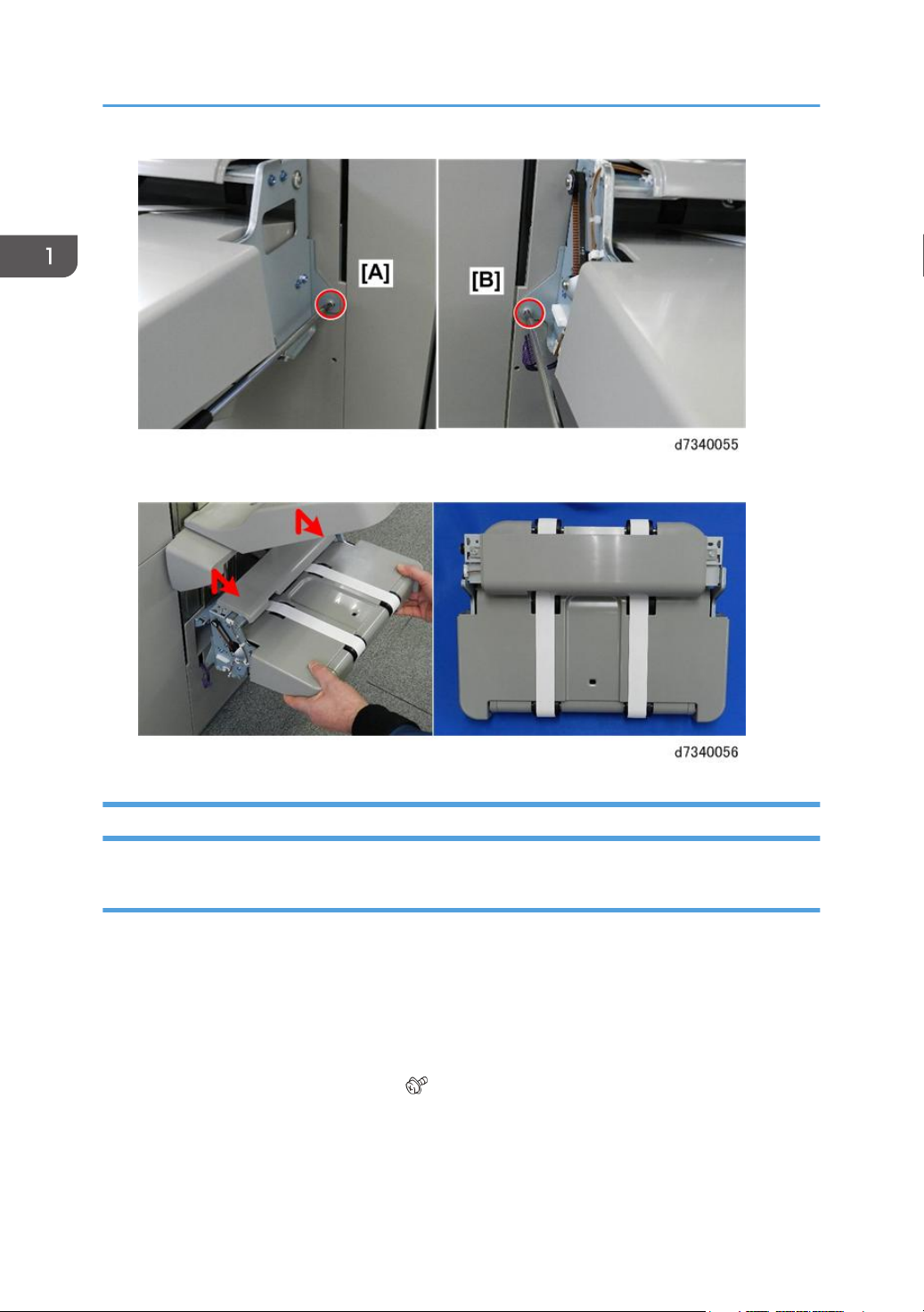
1. Replacement and Adjustment
6. Lift tray off the side of the machine.
Booklet Unit
Booklet Stapler
The booklet stapler weighs about 3 kg (6.6 lb.)
Preparation
• Open the front door.
• Pull stack/stapler unit out with Rb12.
1. Remove both booklet staplers.
2. Remove booklet stapler unit cover [A] ( x2)
28
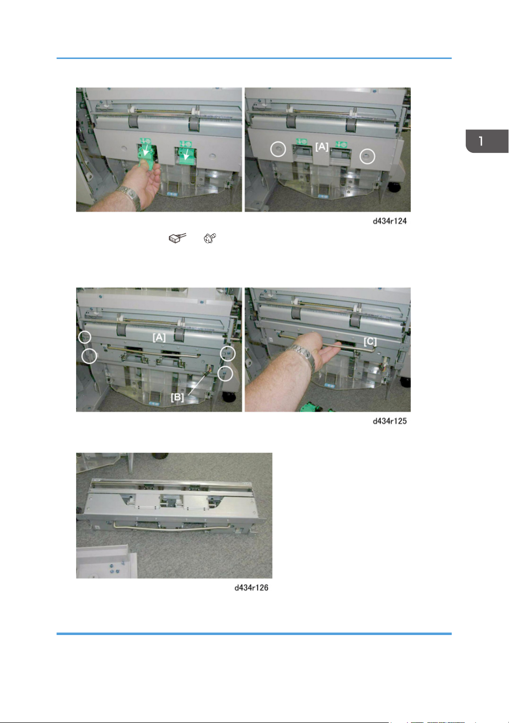
3. Remove stapler unit [A] ( x1, x4)
4. Make sure connector [B] is disconnected.
5. Remove the stapler unit with its handle [C].
Common Procedures
6. Lay the unit on a flat, clean surface.
Booklet Unit Removal
Preparation
29
 Loading...