

Page 1

SHIFT TRAY UNIT
(Machine Code: B313)
Page 2

20 September 1999 SPECIFICATIONS
1 OVERALL MACHINE INFORMATION
1.1 SPECIFICATIONS
Paper Size: Standard Size:
A5 lengthwise to A3
HLT lengthwise to DLT
Non-standard Size:
Paper Width: 90 ~ 297 mm
Paper Length:148 ~ 432 mm
Paper Weight: 60 ~ 105 g/m², 16 ~ 28 lbs.
Tray Capacity: 125 sheets (80 g/m², 20 lbs.)
Power Source: 5 VDC, 24 VDC (from the copier)
Power Consumption: 17 W
Weight: 1.1 kg
Size (W x D x H):
530 mm x 410 mm x 120 mm
B313-1
Options
Page 3
COMPONENT LAYOUT 20 September 1999
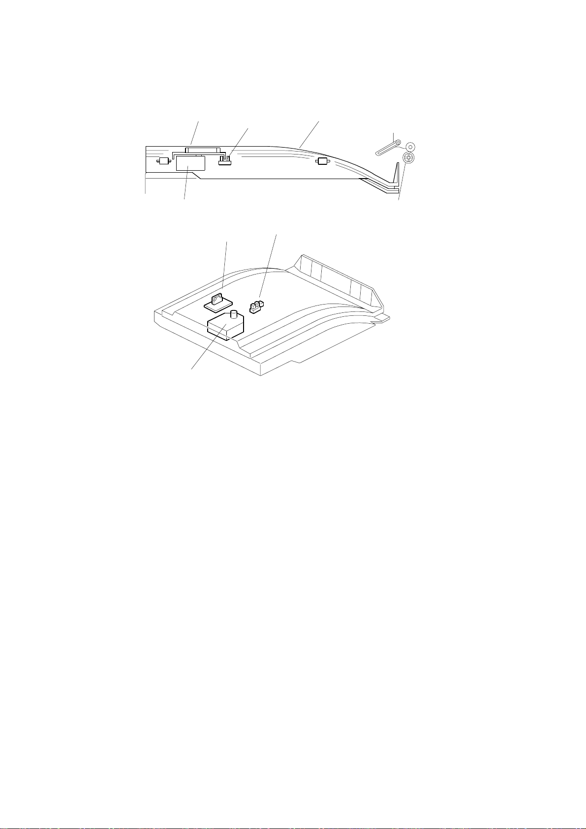
1.2 COMPONENT LAYOUT
1
23
4
B313D101.WMF
5
1
4
B313D102.WMF
1. Half Turn Sensor
2. Tray Cover
3. Slip Disc
4. Tray Motor
5. Driver PCB
B313-2
Page 4

20 September 1999 BASIC OPERATION
2. DETAILED SECTION DESCRIPTIONS
2.1 BASIC OPERATION
[A]
B313D500.WMF
The shift tray allows copies to be sorted into separate piles on one tray.
From the left-right movement of the tray cover [A], the piles of copies are offset into
two positions, slightly overlapping one another.
Options
B313-3
Page 5

PRIMARY MECHANISMS 20 September 1999
2.2 PRIMARY MECHANISMS
2.2.1 TRAY SHIFT
[A]
[C]
[B]
[D]
B313D103.WMF
As stated above, the shift tray cover [A] moves from left to right to create two
possible positions for the copies to stack up. This motion is driven by the tray motor
[B], which connects to the slip disc [C] via a small shaft. The shaft is connected at
the rotational center of the disc. However, there is an off-centered white square
attached to the top surface of the disc. When the tray cover is attached to the unit,
this square fits into a groove [D] (approximately equal to its width) that runs
lengthwise along the underside of the tray
When the motor is running, the disc rotation causes the off-centered white square
to change position. Since the square only has freedom of movement along the
groove [D], the only net motion of the tray is from left to right.
B313-4
Page 6

20 September 1999 PRIMARY MECHANISMS
2.2.2 HALF TURN DETECTION
[C]
[A]
[B]
B313D103.WMF
Half turn detection is performed through a combination of two components: the slip
disc [A] and half turn sensor [C].
The slip disc has a rim extending below the top surface. However, the rim only
extends 180° around the disc. The half turn sensor is below the edge of the disc,
opposite the tray motor. The sensor is positioned so that the rim of the disc passes
between the LED and photo diode when the disc turns.
While the motor [B] is rotating the disc and moving the tray cover, the disc rim is
not between the diode and LED. After the disc has turn ed its max i mum 18 0°, the
rim passes between these two parts and blocks the signal to the LED, stopping the
motor. The tray stays in place until the motor is activated again to move the tray
across to receive another copy of the original.
B313-5
Options
Page 7

TRAY COVER REPLACEMENT 20 September 1999
3. REPLACEMENT AND ADJUSTMENT
3.1 TRAY COVER REPLACEMENT
[A]
[C]
[B]
[D]
[E]
B313R101.WMF
3.1.1 TRAY COVER REMOVAL
1. Remove the tray cover [A] by pressing on the two pawls [B] on the left side of
the cover.
3.1.2 TRAY COVER ATTACHMENT
NOTE:
1. Fit the pawls [C] (just below the cover fin) around the thin bar [D] on the shift
2. Align the square [E] so that it fits into the groove in the underside of the tray
3. Complete the attachment by inserting the left side pawls [B] into place.
The right side of the tray cover should be attached first.
tray.
cover and does not interfere with the attachment of the cover.
B313-6
Page 8

20 September 1999 TRAY MOTOR AND HALF TURN SENSOR REPLACEMENT
3.2 TRAY MOTOR AND HALF TURN SENSOR
REPLACEMENT
[A]
[B]
[C]
B313R102.WMF
3.2.1 REPLACING THE TRAY MOTOR
1. Remove the slip disc [A].
2. Remove the tray motor [B] from the motor holder (1 connector).
3.2.2 REPLACING THE HALF TURN SENSOR:
1. Remove the half turn sensor [C] (1 connector).
B313-7
Options
 Loading...