

Ricoh SF810 Service Manual

6 January 1990
1. SPECIFICATIONS
1. Copy Paper Size: Maximum: A1, D sideways
Minimum: A4, A (81/2 x 11 in) lengthwise
2. Tray Capacity: 100 sheets (Bond Paper)
3. Power Source: +24 volts and +5 volts from the copier
4. Dimensions
(H x W x D):
5. Weight: 25 kg, 55 lb
144 x 1,180 x 772 mm
5.7 x 46.5 x 30.4 in
6-1
6 January 1990
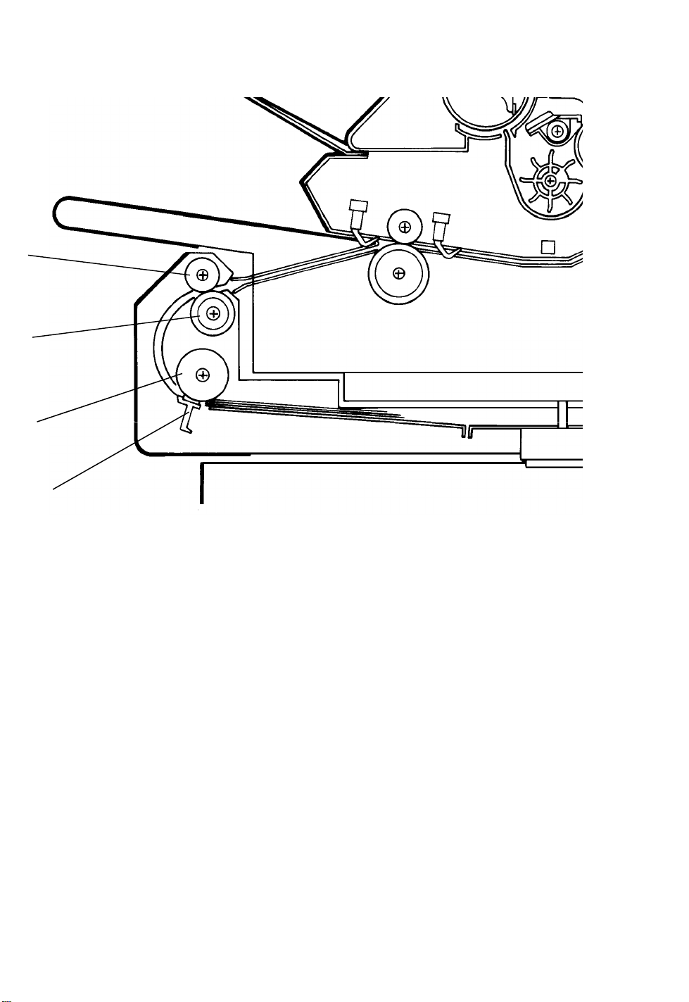
1.1 MECHANICAL COMPONENT LAYOUT
1
2
3
4
1. Upper Relay Roller
2. Lower Relay Roller
3. Paper Feed Roller
4. Friction Pad
6-2
6 January 1990
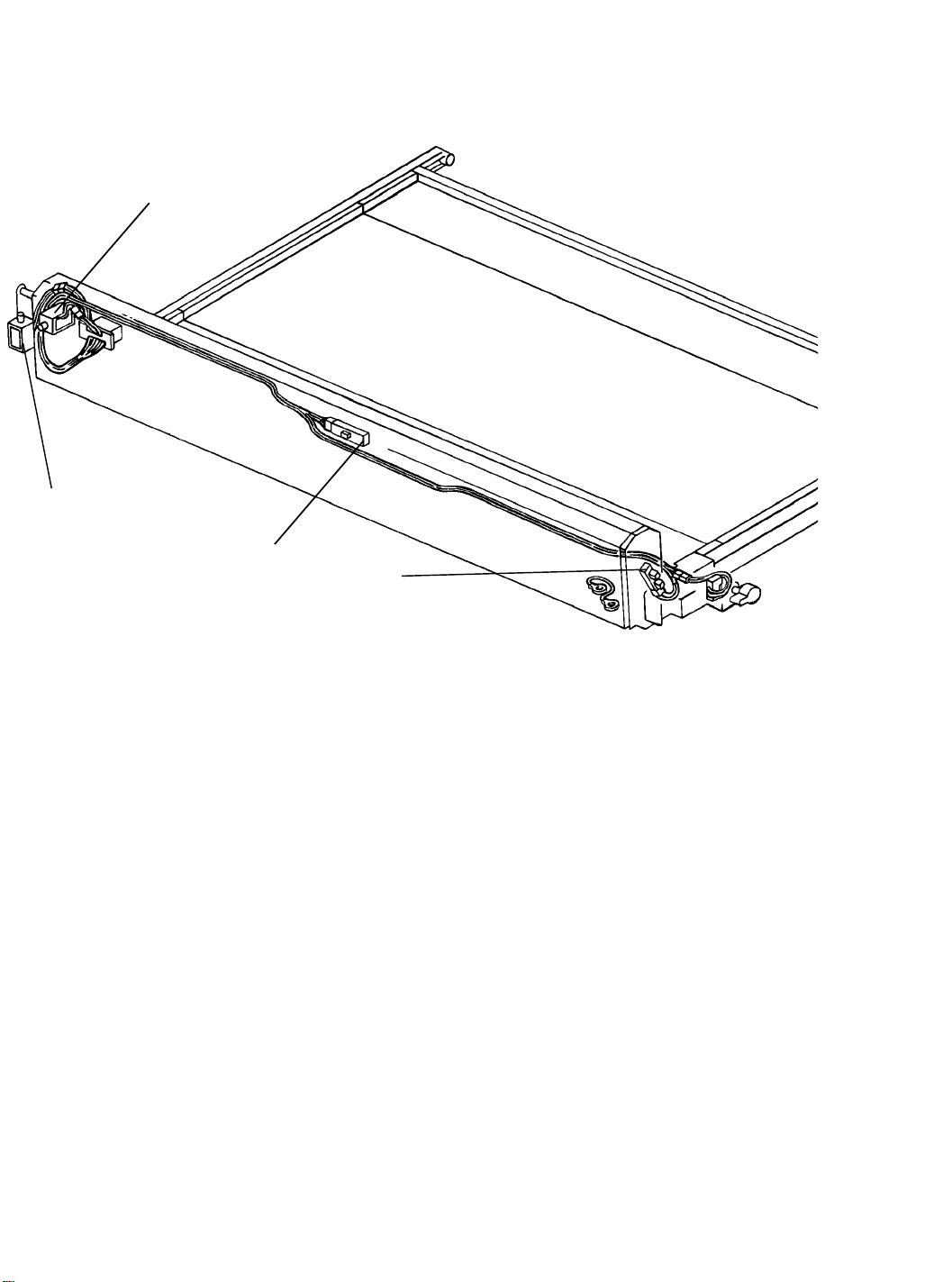
1.2 ELECTRICAL COMPONENT LAYOUT/DESCRIPTIONS
1
2
3
4
SYMBOL NAME FUNCTION LOCATION
Solenoids
SOL10 Auto Feeder
Solenoid 1
SOL11 Auto Feeder
Solenoid 2
Turns the paper feed roller of the auto
sheet feeder.
Turns the relay rollers of the auto sheet
feeder.
1
2
Sensors and Detectors
S18 Auto Sheet
Feeder
Detects misfeeds in the auto sheet
feeder.
3
Sensor
S19 Paper End De-
tector
Detects when the auto sheet feeder
runs out of paper.
4
6-3

6 January 1990
2. BASIC OPERATION
[B]
[D]
[C]
Auto Feeder operation begins when an original is inserted into the original entrance. At this time, the paper feed roller [A] and the relay rollers [B] start
turning. The paper feed roller feeds the top sheet of paper past the friction
pad [C] to the turn guides [D]. The relay rollers then feed the paper to the
manual feed rollers [E]. From that point onwards paper feed continues in the
same way as manual feed.
This model uses the friction pad method for paper feeding. The pressure of
the friction pad must be more stronger for translucent paper than for bond
paper.
[E]
[A]
The friction lever can be used to change the pressure of the friction pad.
There are three settings.
Position Pressure Kind of Paper
1 standard Bond Paper
2 stronger Translucent Paper (A3, A4)
3 strongest Translucent Paper (A1, A2)
NOTE: When position 3 is selected, the copy paper feeding speed becomes
slower and paper/original registration will not function properly. To
correct for this, the CPU delays original feed, and as a result, the
copying speed becomes half (1/2) of standard speed.
6-4
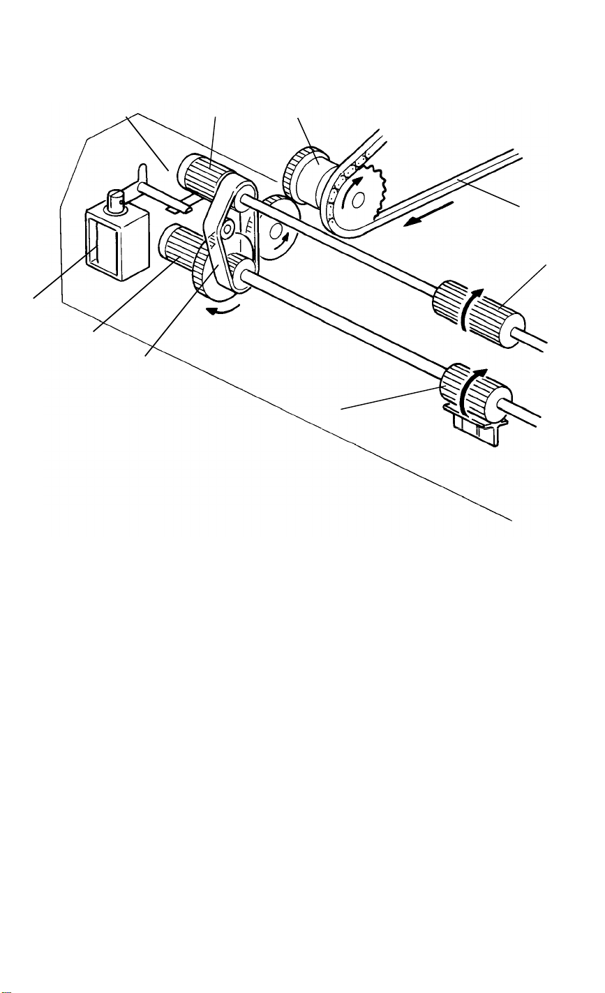
2.1 DRIVE MECHANISM
6 January 1990
[G]
[E]
[D]
[C]
[H]
[B]
[A]
[F]
[I]
Constant drive is provided from the main motor via the paper feed drive chain
[A], to the drive sprocket [B], through some gears, and to the feed drive belt
[C].
Engaging and disengaging auto feeder solenoid 1 [D] allows the spring clutch
[E] to turn, thus driving the relay roller [F]. Engaging and disengaging auto
feeder solenoid 2 [G] allows the spring clutch [H] to turn, thus driving the paper feed roller [I].
6-5

6 January 1990
3. ENVIRONMENT
1. Temperature Range: 10oC to 30oC (50oF to 86oF)
2. Humidity range: 15% to 90% RH
3. Ambient Illumination: Less than 1,500 Lux (do not exposure to direct
sunlight).
4. Ventilation: Room air should turn over at least 3 times/hour.
5. Ambient Dust: Less than 0.15 mg/m
3
(4 x 10
-3
oz/yd
3
)
6. Room Size: More than 10 m3 (13.4 yd3)
7. If the installation place is air-conditioned or heated, place the machine as
follows:
a) Where it will not be subjected to sudden temperature changes
from low to high, or vice versa.
b) Where it will not be directly exposed to cool air from an air
conditioner in the summer.
c) Where it will be directly exposed to reflected heat from a space
heater in the winter.
8. Avoid placing the machine in an area filled with corrosive gases.
9. Avoid any area higher than 2,000 m (6,500 ft) above sea level.
10. Place the machine on a strong and level base.
11. Avoid any area where the machine may be subjected to frequent strong
vibration.
6-6
 Loading...