How it Works
Log In / Sign Up
Buy Points
How it Works
FAQ
Contact Us
Questions and Suggestions
Users
Datasheet
Loading...
R
R5110210XXWA
R5110215XXWA
R5110410XXWA
R5110415XXWA
R5110610XXWA
R5110615XXWA
R5110815XXWA
R5111010XXWA
R5111015XXWA
R5205CND
R5220x
R5312L001A
R5322N
2
R5323x
2
R5325K
R5325x
R5326K
R5326x
R5328K
2
R5400N
R5402N
R5403x
R5405x
R5421N111C-TR
R5421N112C-TR
R5421N151F-TR
R5421N152F-TR
R5422N111C
R5422N111E
R5422N112C
R5422N112E
R5432V
R5433V
R5434D
R5440N201A-TR
R5460x
2
R5461K
R5462K
R5463K
R5470x
R5471x
R5496
R550
R5505
R5509-42
R5509-43
R5509-72
R5509-73
R5520H
2
R5523N
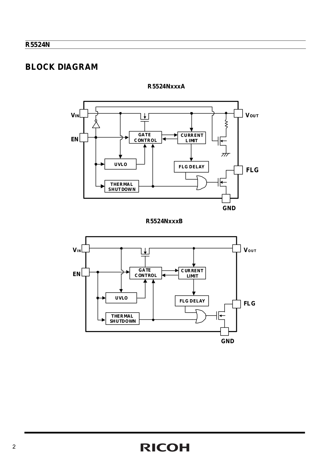
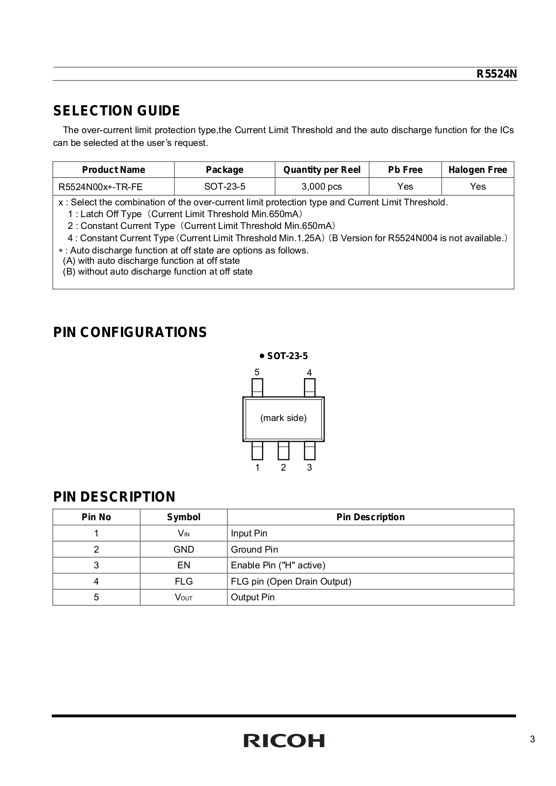
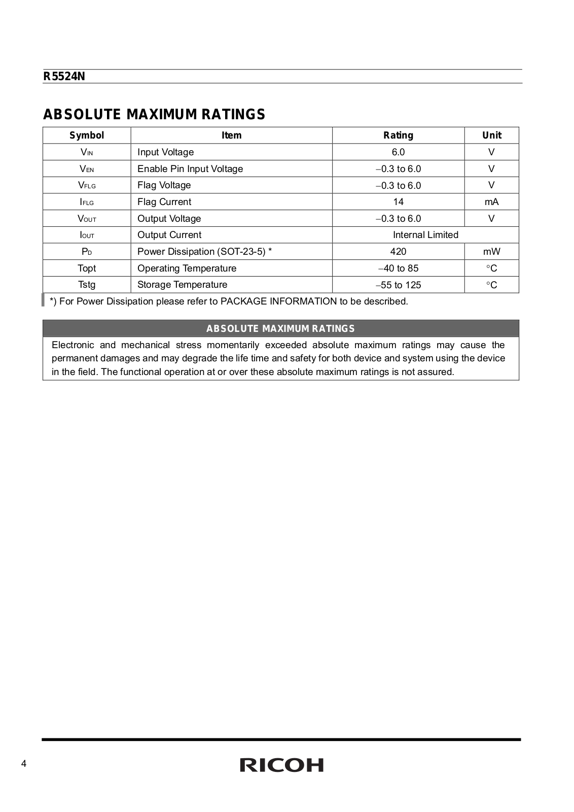
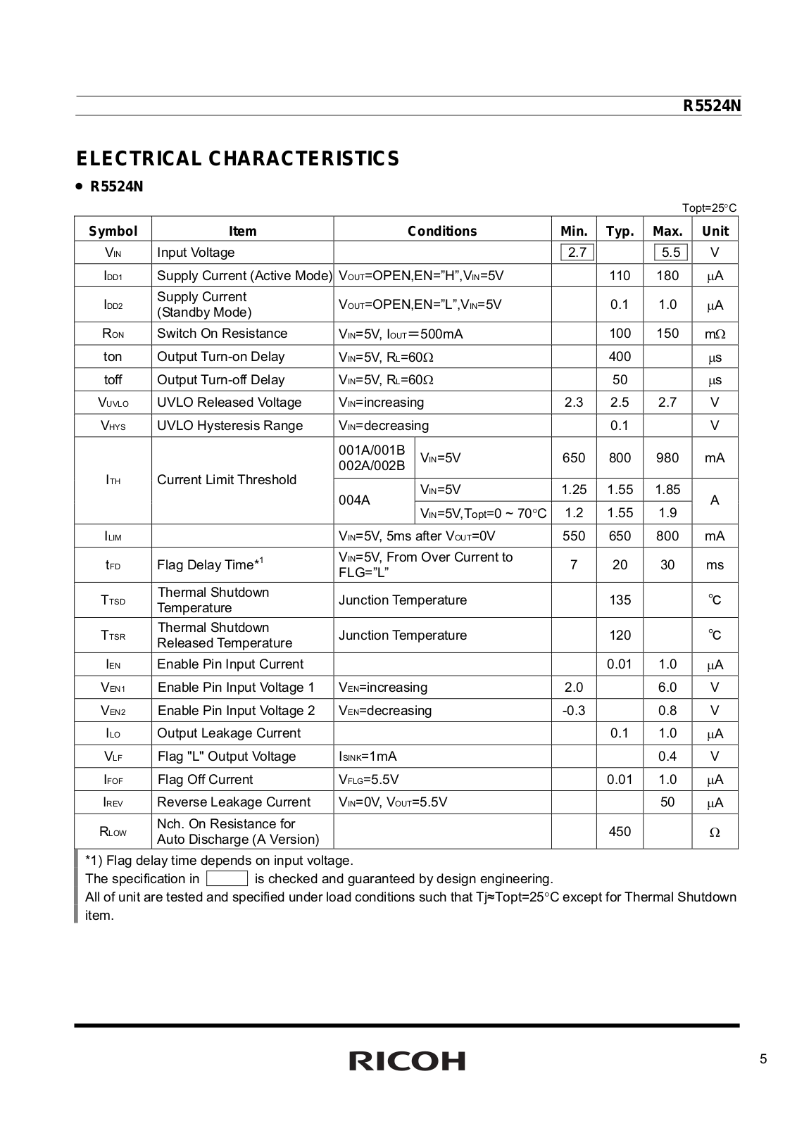
R5524N
R5533V
R5540K
R5611
R5611-01
R580
R5900U
R5900U-00-M4
R5912
R5924
R5929
R5984
R60
R6000F
R6001425XXYA
R6001430XXYA
R6001625XXYA
R6001630XXYA
R6001830XXYA
R6002025XXYA
R6002030XXYA
R6002225XXYA
R6002425XXYA
R6002625XXYA
R6004CND
R6006AND
R6006ANX
R6008ANX
R6008FNJ
R6008FNX
R6010ANX
R6011225XXYA
R6011230XXYA
R6011425XXYA
R6011430XXYA
R6011625XXYA
R6011630XXYA
R6011830XXYA
R6012025XXYA
R6012030XXYA
R6012225XXYA
R6012425XXYA
R6012625XXYA
R6012ANJ
R6012ANX
R6012FNX
R6015ANJ
R6015ANX
R6015ANZ
R60 series
2
Loading...
Loading...
Nothing found
R5524N
Datasheet (RICOH)
15 pgs
408.01 Kb
0
Table of contents
Loading...
Datasheet R5524N Datasheet (RICOH)
...
Datasheet Datasheet (RICOH)
Download
Specifications and Main Features
Frequently Asked Questions
User Manual
Download
Loading...
+
hidden pages
Unhide
You need points to download manuals.
1 point = 1 manual.
You can buy points or you can get point for every manual you upload.
Buy points
Upload your manuals


")