

Ricoh Pro C9200, Pro C9210 Operating Instructions Manual

Operating Instructions
Advanced Settings for Custom Paper
For safe and correct use, be sure to read Safety Information before using
the machine.


TABLE OF CONTENTS
1. Introduction
Basic Procedure.................................................................................................................................................. 3
Advanced Settings..............................................................................................................................................4
2. Printing Process
Overview.............................................................................................................................................................5
Laser Exposure....................................................................................................................................................7
Laser Unit (Exposure)..................................................................................................................................... 7
Development....................................................................................................................................................... 8
Development...................................................................................................................................................8
Drum-to-Belt Transfer....................................................................................................................................... 10
Drum-to-Belt Transfer...................................................................................................................................10
Belt-to-Paper Transfer...................................................................................................................................... 11
Belt-to-Paper Transfer..................................................................................................................................11
PTR Rotation Speed......................................................................................................................................13
Fusing................................................................................................................................................................ 14
Fusing Unit.................................................................................................................................................... 14
Fusing Nip Width Adjustment..................................................................................................................... 15
Fusing Cleaning Unit....................................................................................................................................15
Fusing Belt Smoothing Roller.......................................................................................................................16
Paper Delivery..................................................................................................................................................18
Mainframe....................................................................................................................................................18
Decurl Unit....................................................................................................................................................21
Vacuum Feed LCIT....................................................................................................................................... 22
3. Details of Advanced Settings
Overview.......................................................................................................................................................... 25
Print Mode....................................................................................................................................................25
Registration....................................................................................................................................................... 26
Image Position/Magnification....................................................................................................................26
Image Quality...................................................................................................................................................27
Maximum Image Density............................................................................................................................ 27
Drum-to-belt Transfer Current..................................................................................................................... 27
Belt-to-paper Transfer..................................................................................................................................28
Fusing............................................................................................................................................................30
1

Paper Feed/Delivery....................................................................................................................................... 35
Main Tray/Vacuum Feed LCIT...................................................................................................................35
Adjusting the Machine’s Paper Delivery and Output............................................................................... 40
2

1. Introduction
This chapter provides an overview of the Media Library.
Basic Procedure
ProC9200/C9210 Series is capable of printing on a wide variety of media using the latest
technologies in digital printing such as the AC transfer and elastic fusing belt.
In addition to these technologies, support of various media is also made possible by the Media Library
database, which is registered with tested and proved media and programmed with optimized print
parameters by media type/weight.
How to use the Media Library:
1. Select a media from the library and associate the media to a tray.
2. Set the media on the associated tray.
3. Specify the media in Job Properties of the color controller.
3
DZH310
1. Introduction
Advanced Settings
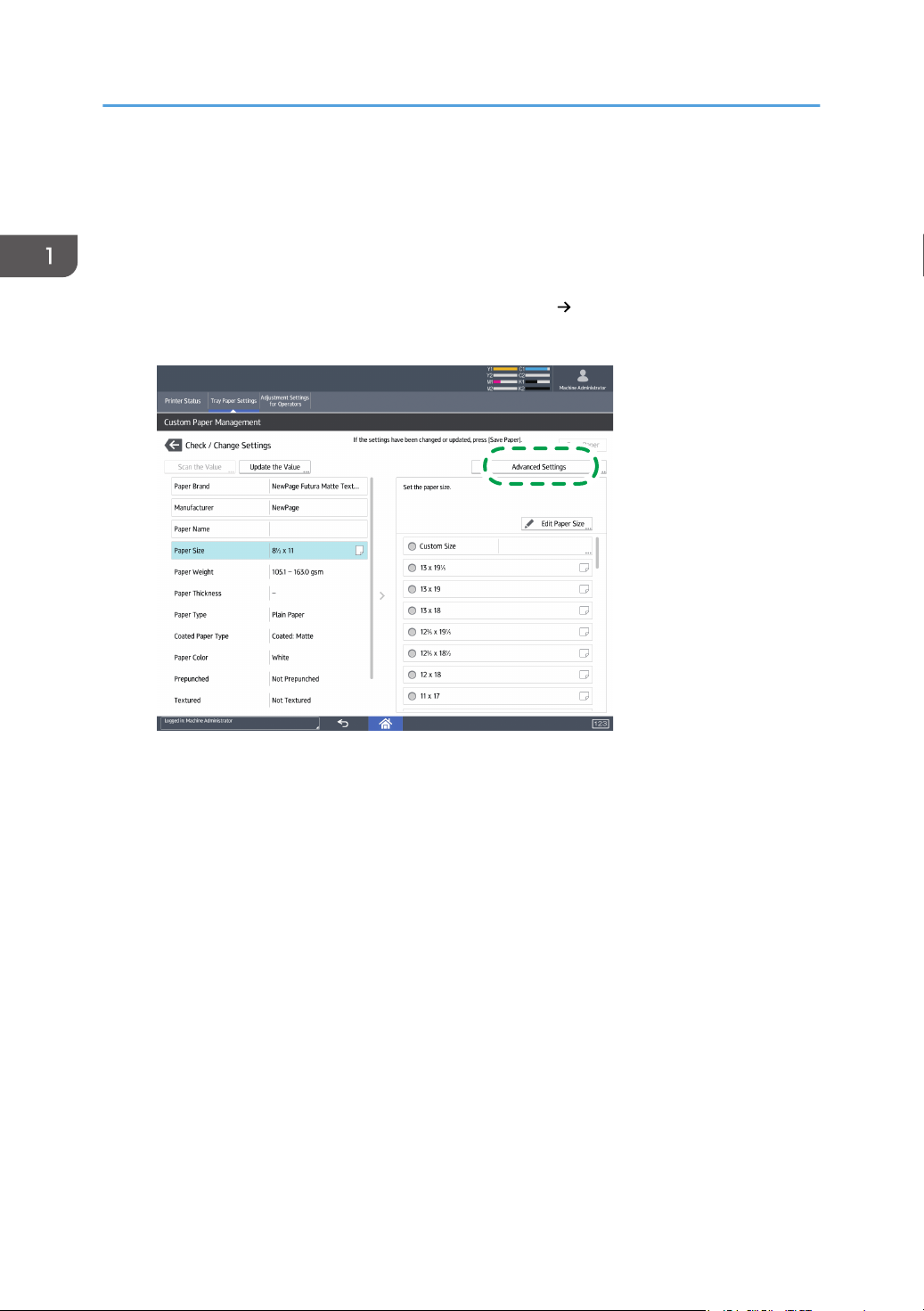
Printing from the Media Library is possible with a simple procedure, however, precise adjustments (such
as the transfer and fusing conditions) may be required depending upon the media attributes, which differ
by each and every media.
Such precise adjustments can be made from [Tray Paper Settings] [Advanced Settings].
In this menu, the followings can be adjusted:
• Machine: Image Position
• Machine: Image Quality
• Machine: Paper Feed / Output
To effectively adjust the above, it is important to have a basic understanding of how the printer works.
4
2. Printing Process
YMCK
DZH300
1
2
2
3
4
5
7
6
8
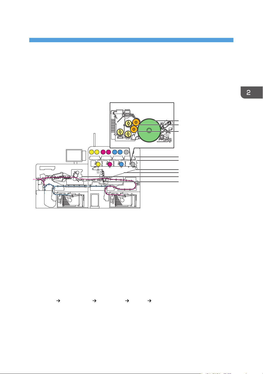
This chapter provides explanation on the basic Xerographic process of the engine by referring to the
items of the Advanced Settings.
Overview
1. OPC drum
2. Development roller
3. Laser unit
4. Charge roller
5. Intermediary transfer belt(ITB)
6. Image transfer roller
7. Fusing unit
8. Paper transfer roller(PTR)
The printing process consists of the following steps:
Drum charge Laser exposure Development Transfer Fusing
• Drum charge …… The charge roller [4] gives an equal charge across the surface of the OPC drum
[1].
• Laser exposure …… Laser unit [3] creates an electrostatic latent image on the OPC drum [1].
5

2. Printing Process
• Development …… The development roller [2] carries toner to the latent image on the OPC drum
[1].
• Image transfer
Drum-to-belt transfer …… Toner images created on each OPC drum [1] are transferred sequentially
to the ITB [5].
Belt-to-paper transfer …… Toner image on the ITB [5] is transferred onto the paper when the paper
passes through the PTR [8].
• Fusing …… The fusing unit [7] applies heat and pressure to fuse the toner image onto the paper.
6

1
2
3
4
DZH003
Laser Exposure
Laser Exposure
Laser Unit (Exposure)
The laser unit is equipped with the Vertical Cavity Surface Emitting Laser (VCSEL) technology.
40 laser beams are emitted to produce 2400dpi×4800dpi.
Laser beams are reflected on the polygon mirror and lenses to create a latent image on each of the
photoconductive drums by imparting static electricity on the surface of the drum.
1. VCSEL
2. Polygon mirror
3. OPC drum
4. Laser beam
Adjusting the start timing and frequency of this latent image creation process in both main and sub scan
directions enables registration, masking and scaling of the image.
Main scan direction ... Across the paper feed direction
Sub scan direction ... Along the paper feed direction
Related Advanced Settings
page 26 "Image Position/Magnification"
page 32 "Erase margin: leading/trailing edge"
7

1
2
1
DZH301
[A]
6
5
4
3
2
1
DZH302
2. Printing Process
Development
Development
The development system employs the dual-component*1 development method.
The developer is pre-mixed*2 to prevent image quality degradation caused by deterioration of the
developer that occurs over time.
Electrostatic latent image areas of the drum attract negatively charged toner particles from the
development roller [1].
To maintain consistent amount of toner attraction from the development roller [1] to the drum [2] for
stable image quality(toner density), image quality adjustment process runs automatically when turning
on the machine power and at optimum timings.
The developer consists of positively charged carrier (+) and negatively charged toner (-).
*1
The carrier is pre-mixed with the toner in the toner bottle and the mixture is supplied to the development unit to
*2
constantly refresh old developer in the development unit with new developer.
During the image quality adjustment process, toner patterns in 10 gradients are created on the ITB for
each toner color, which are read by the toner mark sensors. Xerographic conditions are adjusted
according to the sensor readings, maintaining consistent development (maximum image density).
8

Related Advanced Settings
page 27 "Maximum Image Density"
Development
9
12 3
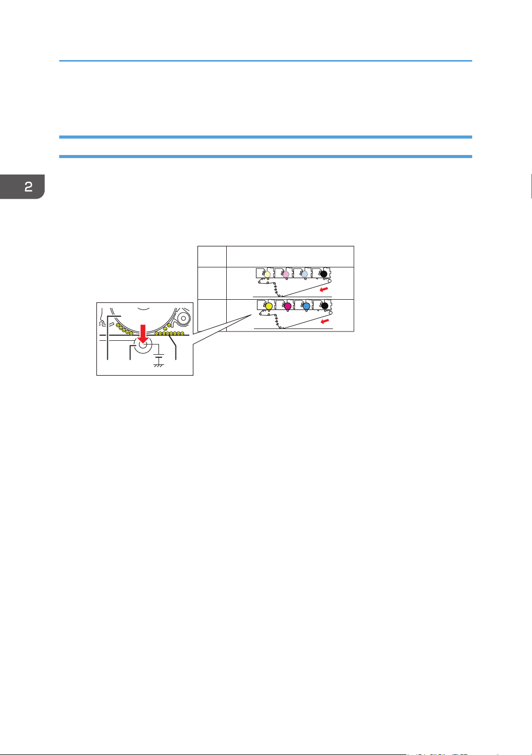
BW
FC
Print
mode
Engine status
(Stations greyed out are inactive.)
Paper
Paper
YMC
Y M
C
K
K
DZH308
2. Printing Process
Drum-to-Belt Transfer
Drum-to-Belt Transfer
Among the following two print modes, the correct mode is selected automatically according to the print
data sent from the printer controller.
• BW mode: Job contains only black data.
• FC mode: Job contains color data.
1. OPC drum
2. Image transfer roller
3. Intermediary transfer belt(ITB)
By applying a positive (+) bias (transfer current) to the image transfer roller, negatively charged toner (-)
on the drum is attracted to the ITB that positions between the roller and the belt. Any remaining toner on
the drum is cleaned by the drum cleaning unit.
Related Advanced Settings
page 27 "Drum-to-belt Transfer Current"
10
DZH307
1
2
Belt-to-Paper Transfer
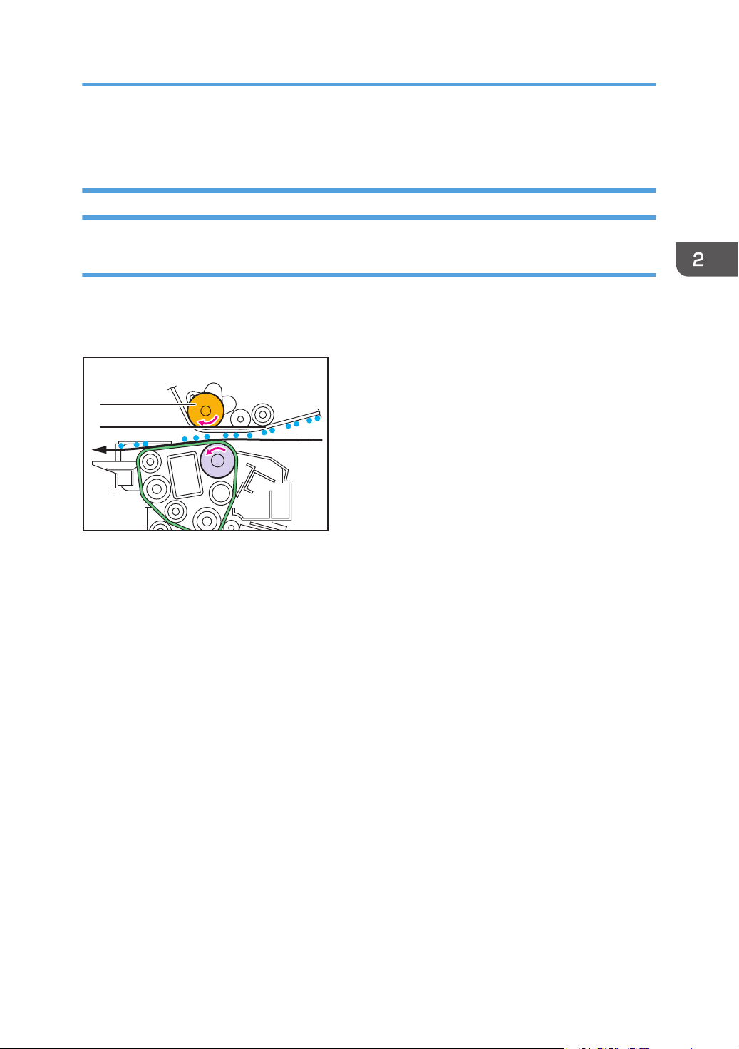
Belt-to-Paper Transfer
Belt-to-Paper Transfer
Applied voltage
The paper transfer roller features AC transfer technology.
Negatively charged toner image (-) on the ITB [2] is transferred to the paper by applying a negative
bias (-) to the paper transfer bias roller [1].
Following are the three types of negative bias applied to the paper transfer bias roller:
• DC bias: For all media types
• AC bias (Standard): For media other than metallic pearl and textured paper
• AC bias (Textured): For textured paper
* At low temperature and humidity, only DC bias is applied.
Bias is adjustable by print mode because the optimum bias level is dependent on the amount of toner
transfer.
(Bias is higher for FC than for BW due to the greater amount of transferred toner.)
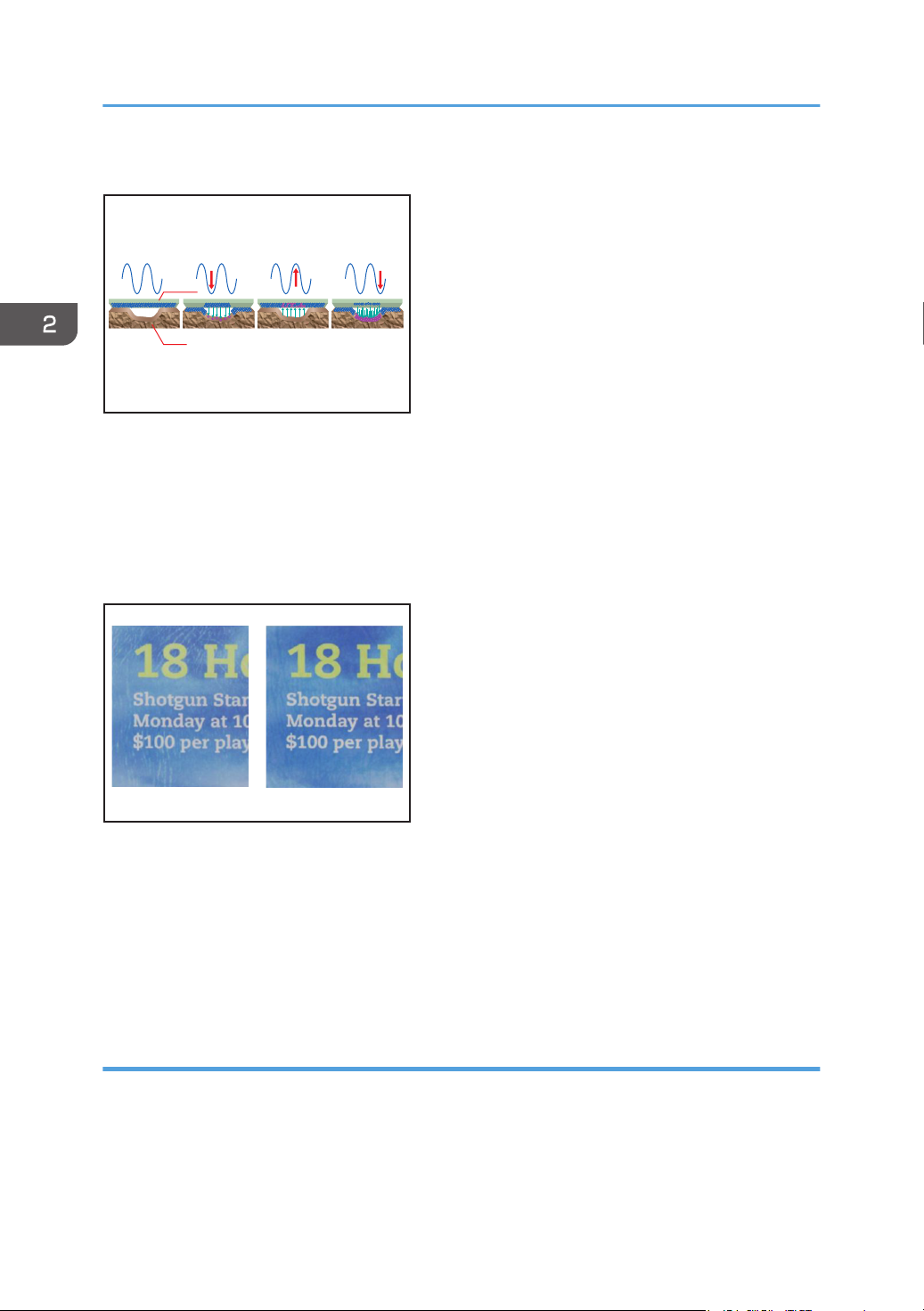
By nature of AC, in which the current flows in an alternating up-and-down movement, toner particles
sync with this movement. Toner transferred to the media is pulled back to the ITB to gain further
transferability, enabling toner particles to fall into the indentations on rough surfaced media.
11
1
2345
DZH009
DZH010
12
2. Printing Process
Textured paper mode
1. ITB
2. Textured paper
3. Toner is partially transferred.
4. Toner transferred to the paper returns to the belt and combines with toner remaining on the belt.
5. Toner is transferred to the indentations on the surface of the paper.
1. AC transfer inactive
2. AC transfer active
Related Advanced Settings
• DC bias
page 28 "Paper transfer current"
Leading/Trailing edge correction
To prevent image quality problems owing to the instability of the leading/trailing edges of the paper
when entering the nip of the PTR, the belt-to-paper transfer bias is adjusted for the leading/trailing
edges.
• Belt-to-paper transfer: Leading edge correction
12
• Belt-to-paper transfer: Trailing edge correction
DZH304
1
• Belt-to-paper transfer: Length of area to apply correction at leading edge of paper
• Belt-to-paper transfer: Length of area to apply correction at trailing edge of paper
• Current vs. Voltage
• Bias is applied using 'constant current' for drum-to-belt and belt-to-paper transfer, as this
method is resilient to changes in operational environment and thickness of the media.
• On the other hand, 'constant voltage' is used for AC bias and as this method does not require
adjustments according to paper width.
Related Advanced Settings
page 29 "Belt-to-paper transfer correction: LE/TE"
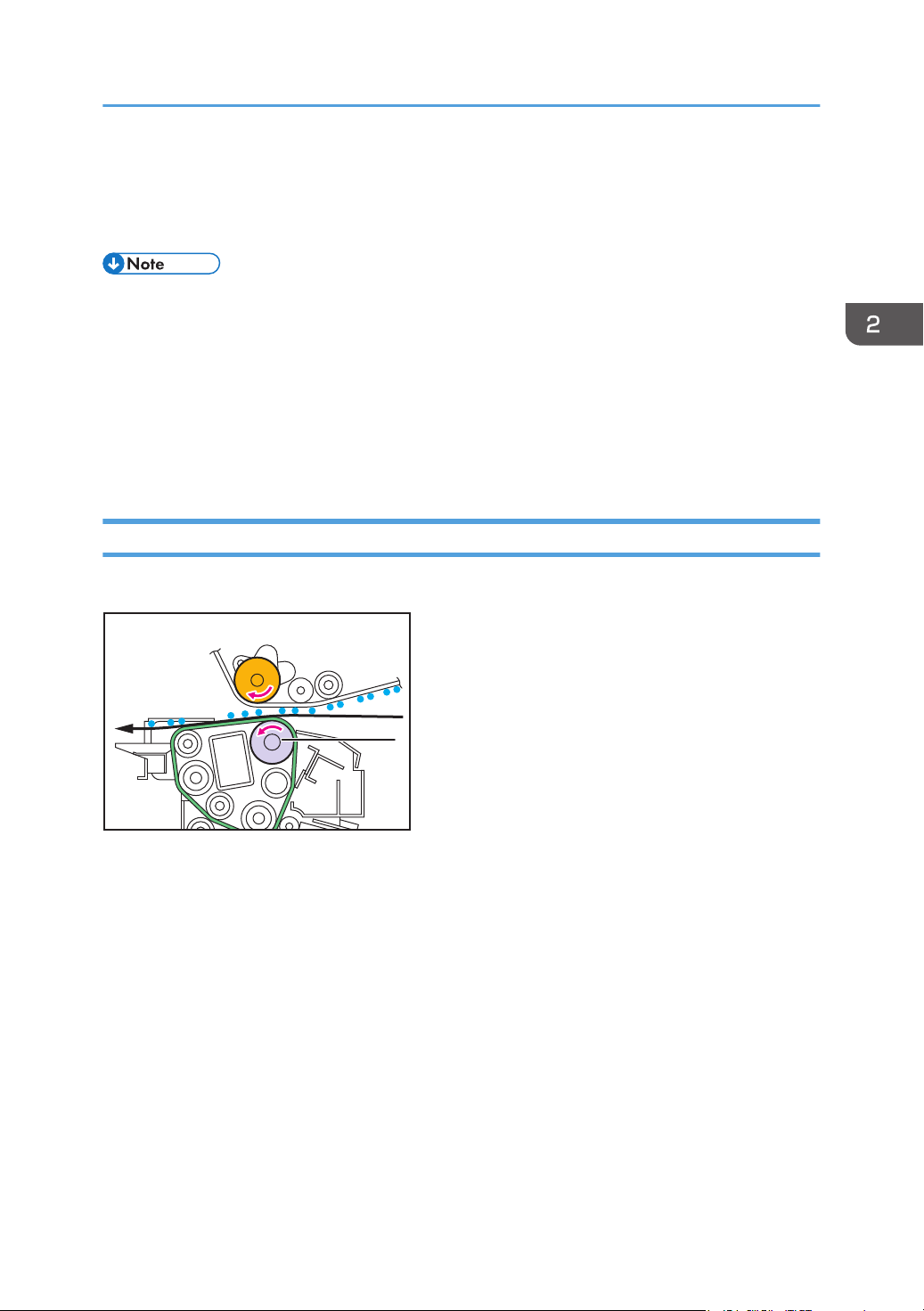
PTR Rotation Speed
The PTR [1] has the function to deliver the paper from the paper transfer timing roller.
Belt-to-Paper Transfer
Since the paper transport speed is controlled by the PTR, if the PTR rotation speed is slower than the
target the image will shrink, if faster than the target the image will stretch.
A problem such as side-to-side image magnification misalignment and mottling on black half-tone parts
may occur in the printed image because of the speed difference relative to the image transfer belt. To
solve this problem, it is necessary to adjust the PTR rotation speed.
Since the paper is simultaneously gripped by the PTR and the paper transfer timing roller, uneven density
and banding problems may occur, if the speed differs between these rollers. To prevent this problem,
you can adjust the PTR rotation speed.
Related Advanced Settings
page 42 "Paper transfer roller speed"
page 42 "Transfer timing roller feed speed"
13
 Loading...