

Ricoh PE-P1, PE-MF1 Service Manual

Model PE-P1/MF1
Machine Code:
G165/G166/G167 Printers
and
G181/G183/G184 Copiers
SERVICE MANUAL
Nov. 2007
Subject to change

Safety Notices
Important Safety Notices
Prevention of Physical Injury
1. Before disassembling or assembling parts of the printer and peripherals, make sure that the printer
power cord is unplugged.
2. The wall outlet should be near the printer and easily accessible.
3. If any adjustment or operation check has to be made with exterior covers off or open while the main
switch is turned on, keep hands away from electrified or mechanically driven components.
4. The printer drives some of its components when it completes the warm-up period. Be careful to keep
hands away from the mechanical and electrical components as the printer starts operation.
5. The inside and the metal parts of the fusing unit become extremely hot while the printer is operating.
Be careful to avoid touching those components with your bare hands.
Health Safety Conditions
Toner is non-toxic, but if you get either of them in your eyes by accident, it may cause temporary eye
discomfort. Try to remove with eye drops or flush with water as first aid. If unsuccessful, get medical attention.
Observance of Electrical Safety Standards
The printer and its peripherals must be serviced by a customer service representative who has completed
the training course on those models.
Safety and Ecological Notes for Disposal
1. Do not incinerate toner bottles or used toner. Toner dust may ignite suddenly when exposed to an
open flame.
2. Dispose of used toner, the maintenance unit which includes developer or the organic photoconductor
in accordance with local regulations. (These are non-toxic supplies.)
3. Dispose of replaced parts in accordance with local regulations.
• To prevent a fire or explosion, keep the machine away from flammable liquids, gases, and aerosols.
A fire or an explosion might occur.
1
• The Controller board on the MF model contains a lithium battery. The danger of explosion exists if a
battery of this type is incorrectly replaced. Replace only with the same or an equivalent type
recommended by the manufacturer. Discard batteries in accordance with the manufacturer's
instructions and local regulations.
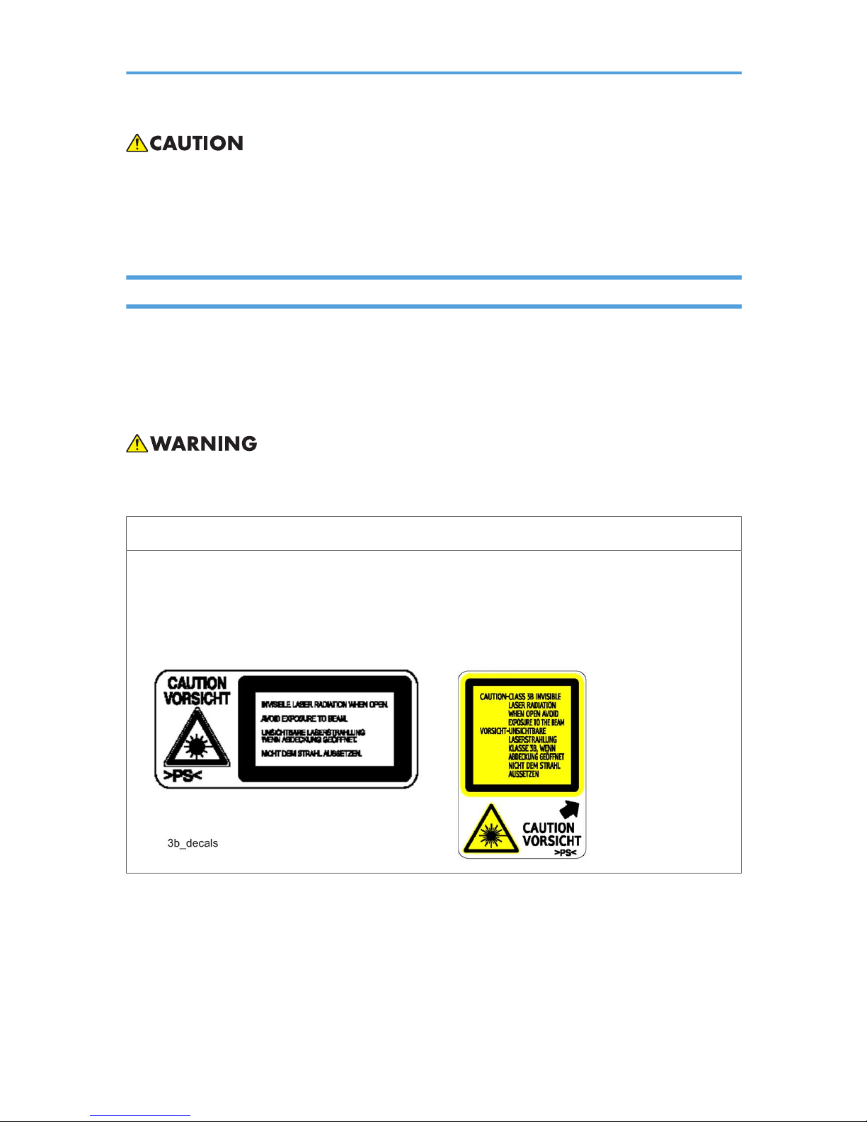
Laser Safety
The Center for Devices and Radiological Health (CDRH) prohibits the repair of laser-based optical units
in the field. The optical housing unit can only be repaired in a factory or at a location with the requisite
equipment. The laser subsystem is replaceable in the field by a qualified Customer Engineer. The laser
chassis is not repairable in the field. Customer engineers are therefore directed to return all chassis and
laser subsystems to the factory or service depot when replacement of the optical subsystem is required.
• Use of controls, or adjustment, or performance of procedures other than those specified in this manual
may result in hazardous radiation exposure.
WARNING
WARNING:
Turn off the main switch before attempting any of the procedures in the Laser Optics Housing Unit section.
Laser beams can seriously damage your eyes.
CAUTION MARKING:
2

Symbols, Abbreviations and Trademarks
This manual uses several symbols and abbreviations. The meaning of those symbols and abbreviations are
as follows:
* See or Refer to
Clip ring
Screw
Connector
Clamp
E-ring
SEF Short Edge Feed
LEF Long Edge Feed
Trademarks
Microsoft®, Windows®, and MS-DOS® are registered trademarks of Microsoft Corporation in the United
States and /or other countries.
PostScript® is a registered trademark of Adobe Systems, Incorporated.
PCL® is a registered trademark of Hewlett-Packard Company.
Ethernet® is a registered trademark of Xerox Corporation.
PowerPC® is a registered trademark of International Business Machines Corporation.
Other product names used herein are for identification purposes only and may be trademarks of their
respective companies. We disclaim any and all rights involved with those marks.
3

TABLE OF CONTENTS
Safety Notices.....................................................................................................................................................1
Important Safety Notices...............................................................................................................................1
Laser Safety.....................................................................................................................................................2
Symbols, Abbreviations and Trademarks.........................................................................................................3
Trademarks.....................................................................................................................................................3
1. Installation
Installation Requirements.................................................................................................................................11
Environment..................................................................................................................................................11
Machine level...............................................................................................................................................11
Machine Space Requirement.....................................................................................................................11
Power Requirements....................................................................................................................................13
Installation Procedure..................................................................................................................................13
2. Preventive Maintenance
Preventive Maintenance..................................................................................................................................15
User Replaceable Items...............................................................................................................................15
3. Replacement and Adjustment
Before You Start...............................................................................................................................................17
Special Tools....................................................................................................................................................18
Exterior Covers.................................................................................................................................................19
Rear Cover...................................................................................................................................................19
Operation Panel...........................................................................................................................................20
Right Cover...................................................................................................................................................21
Left Cover......................................................................................................................................................21
Front Cover Unit...........................................................................................................................................22
Laser Optics......................................................................................................................................................24
Caution Decal Locations.............................................................................................................................24
Laser Optics Housing Unit...........................................................................................................................24
AIO Cartridge..................................................................................................................................................29
AIO Cartridge (All In One Cartridge) .......................................................................................................29
Black AIO Motor.........................................................................................................................................29
Color AIO Motor.........................................................................................................................................32
Image Transfer..................................................................................................................................................34
Image Transfer Belt Unit..............................................................................................................................34
4

ITB (Image Transfer Belt) Cleaning Unit.....................................................................................................35
Agitator Motor.............................................................................................................................................36
ITB (Image Transfer Belt) Contact Motor...................................................................................................37
ITB (Image Transfer Belt) Contact Sensor..................................................................................................38
TM (Toner Mark) Sensor Base....................................................................................................................39
Waste Toner Bottle Set Sensor...................................................................................................................40
Waste Toner Overflow Sensor...................................................................................................................42
Paper Transfer..................................................................................................................................................43
Transfer Unit.................................................................................................................................................43
Transfer Roller..............................................................................................................................................43
Registration Roller........................................................................................................................................45
Registration Sensor......................................................................................................................................46
Registration Clutch.......................................................................................................................................46
Image Fusing....................................................................................................................................................48
Fusing Unit....................................................................................................................................................48
Fusing Lamp..................................................................................................................................................49
Transport/Fusing Motor..............................................................................................................................50
Paper Feed........................................................................................................................................................52
Paper Feed Clutch.......................................................................................................................................52
Paper Feed Roller........................................................................................................................................52
Separation Pad............................................................................................................................................53
Paper End Sensor.........................................................................................................................................54
Paper Exit..........................................................................................................................................................56
Paper Exit Roller...........................................................................................................................................56
Paper Exit Sensor.........................................................................................................................................57
Electrical Components.....................................................................................................................................59
Controller Board..........................................................................................................................................59
EGB (Engine Board)....................................................................................................................................62
FCU (G183/G184 only)...........................................................................................................................65
Interlock Switches........................................................................................................................................66
Fusing Fan Motor.........................................................................................................................................67
LSU Fan Motor.............................................................................................................................................67
ID Chip Board..............................................................................................................................................68
5

PSU................................................................................................................................................................69
High Voltage Power Supply Board............................................................................................................71
Temperature/Humidity Sensor...................................................................................................................72
Duplex Motor (Duplex Model)...................................................................................................................72
Speaker (G183/G184 only)....................................................................................................................73
EEPROM.......................................................................................................................................................74
ADF....................................................................................................................................................................78
ADF Unit........................................................................................................................................................78
Original Tray................................................................................................................................................79
ADF Feed Unit..............................................................................................................................................80
ADF Separation Pad....................................................................................................................................80
ADF Front Cover .........................................................................................................................................81
ADF Rear Cover...........................................................................................................................................81
ADF Cover....................................................................................................................................................82
ADF Motor....................................................................................................................................................82
Original Set Sensor......................................................................................................................................84
ADF Cover Open Sensor............................................................................................................................85
ADF Feed Sensor.........................................................................................................................................85
ADF Drive Board..........................................................................................................................................86
Scanner.............................................................................................................................................................88
Scanner Unit.................................................................................................................................................88
Scanner Top Cover......................................................................................................................................90
Scanner Carriage Unit.................................................................................................................................91
Exposure Lamp.............................................................................................................................................93
Lamp Stabilizer Board.................................................................................................................................94
Scanner Motor.............................................................................................................................................95
4. Troubleshooting
Error Codes.......................................................................................................................................................97
Overview......................................................................................................................................................97
Error Codes List............................................................................................................................................97
Service Call Conditions.................................................................................................................................101
Summary....................................................................................................................................................101
Engine SC...................................................................................................................................................101
6

Controller SC.............................................................................................................................................109
Image Problems.............................................................................................................................................111
Overview....................................................................................................................................................111
Image Problem..........................................................................................................................................111
5. Service Tables
Service Program ............................................................................................................................................113
Overview....................................................................................................................................................113
Smart Organizing Monitor (Printer Model).................................................................................................114
Overview....................................................................................................................................................114
Printer Driver Installation (USB Connection)...........................................................................................114
Entering the Printer Configuration............................................................................................................114
Printer Configuration Menu List................................................................................................................116
Service Menu (MF Model)...........................................................................................................................139
Overview....................................................................................................................................................139
Maintenance Mode Menu.......................................................................................................................139
Fax Service Test Menu..............................................................................................................................149
Firmware Updating........................................................................................................................................151
Printer Model.............................................................................................................................................151
MF Model..................................................................................................................................................155
Boot Loader Firmware...............................................................................................................................158
6. Detailed Section Descriptions
Machine Overview........................................................................................................................................159
Component Layout....................................................................................................................................159
Paper Path..................................................................................................................................................160
Drive Layout...............................................................................................................................................161
Electrical Component Layout....................................................................................................................162
Board Structure..........................................................................................................................................165
Printing Process..........................................................................................................................................167
Process Control..............................................................................................................................................169
Overview....................................................................................................................................................169
Process Control Flow.................................................................................................................................169
Process Control Self-check.......................................................................................................................170
Laser Exposure...............................................................................................................................................173
7

Overview....................................................................................................................................................173
Optical Path...............................................................................................................................................174
LD Safety Switch........................................................................................................................................175
MUSIC (Mirror Unit Skew and Interval Correction)...............................................................................176
AIO (All In One) Cartridge...........................................................................................................................177
Overview....................................................................................................................................................177
Drive...........................................................................................................................................................178
OPC Charge and Cleaning......................................................................................................................179
Waste Toner Collection from the OPC....................................................................................................180
Toner Mixing and Transport ....................................................................................................................180
Development Mechanism.........................................................................................................................181
Toner Near End and End Detection.........................................................................................................181
Paper Feed.....................................................................................................................................................183
Overview....................................................................................................................................................183
Drive and Paper End Detection................................................................................................................184
Tray Lift.......................................................................................................................................................185
By-pass Feed.............................................................................................................................................186
Duplex (G167/G183/G184 Only).....................................................................................................187
Image Transfer ..............................................................................................................................................188
Overview....................................................................................................................................................188
Drive and Transfer Belt Roller Bias...........................................................................................................189
Transfer Belt Contact.................................................................................................................................189
ITB (Image Transfer Belt) Cleaning Unit..................................................................................................190
Transfer Roller Overview..........................................................................................................................191
Paper Transfer and Discharge..................................................................................................................192
Waste Toner Collection............................................................................................................................193
Fusing and Exit...............................................................................................................................................194
Overview....................................................................................................................................................194
Drive...........................................................................................................................................................195
Pressure Release Mechanism...................................................................................................................196
Temperature Control.................................................................................................................................197
Controller........................................................................................................................................................200
Overview....................................................................................................................................................200
8

ADF.................................................................................................................................................................204
Overview....................................................................................................................................................204
Paper Path..................................................................................................................................................204
Timing Chart...............................................................................................................................................205
Scanner...........................................................................................................................................................207
Overview....................................................................................................................................................207
Drive...........................................................................................................................................................207
7. Specifications
General Specifications..................................................................................................................................209
Printer Model.............................................................................................................................................209
MF Model..................................................................................................................................................211
Option........................................................................................................................................................217
Supported Paper Sizes..................................................................................................................................218
Machine Configuration.................................................................................................................................220
Printer Model (G165/G166/G167)....................................................................................................220
MF Model (G181/G183/G184).........................................................................................................221
9

10

1. Installation
Installation Requirements
Environment
1. Temperature Range: 10°C to 32°C (50°F to 89.6°F)
2. Humidity Range: 15% to 80% RH
3. Ambient Illumination: Less than 2,000 lux (do not expose to direct sunlight)
4. Ventilation: 3 times/hr/person
5. Do not put the machine in areas that get sudden temperature changes. This includes:
• Areas directly exposed to cool air from an air conditioner
• Areas directly exposed to heat from a heater.
6. Do not put the machine in areas that get exposed to corrosive gas.
7. Do not install the machine at locations over 2,500 m (8,125 ft.) above sea level.
8. Put the machine on a strong, level base. (Inclination on any side must be no more than 5 mm.)
9. Do not put the machine in areas with strong vibrations.
Machine level
Front to back: Within 5 mm (0.2") of level
Right to left: Within 5 mm (0.2") of level
Machine Space Requirement
Put the machine near the power source with these clearances:
11
1
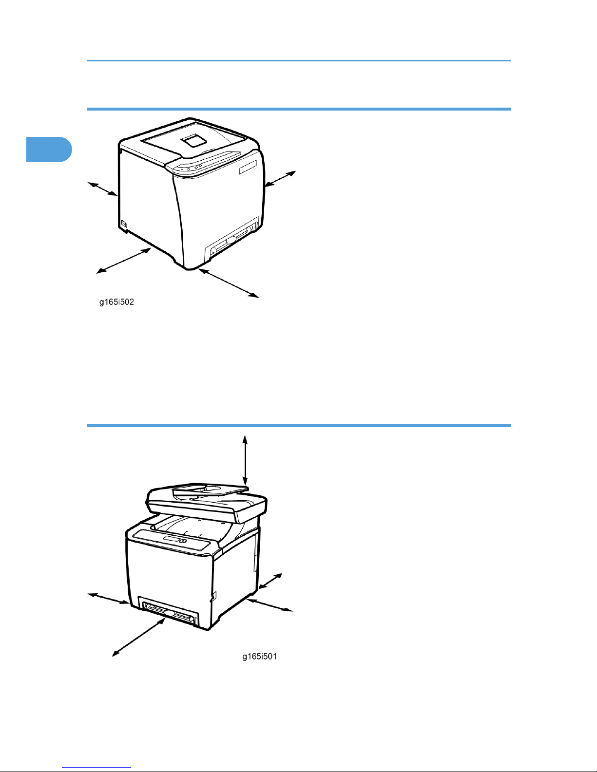
Printer Model
Left side: Over 20 cm (7.9")
Rear: Over 10 cm (4")
Right side: Over 10 cm (4")
Front: Over 70 cm (27.5")
MF Model
Left side: Over 20 cm (7.9")
Rear: Over 20 cm (7.9")
1. Installation
12
1
Right side: Over 10 cm (4")
Front: Over 70 cm (27.5")
Top: Over 24 cm (9.5")
Power Requirements
• Make sure that the plug is tightly in the outlet.
• Avoid multi-wiring.
• Make sure that you ground the machine.
Input voltage level
120 V, 60 Hz: More than 11 A (for North America)
220 V to 240 V, 50 Hz/60 Hz: More than 6 A (for Europe/ Asia)
Permitted voltage fluctuation: 10%
Do not set anything on the power cord.
Installation Procedure
Refer to the Quick Installation Guide for details about installing the machine.
Installation Requirements
13
1

1. Installation
14
1

2. Preventive Maintenance
Preventive Maintenance
User Replaceable Items
Item Yield
Print Cartridge (AIO) Approx. 2 k prints/cartridge
Waste Toner Bottle
Approx. 25 k prints/ bottle
(See condition 4)
Condition:
1. An A4 (8.5"x11")/ 5% chart is used to measure the above yield.
2. The condition is standard temperature and humidity.
3. These yield values may change depending on the circumstances and printing conditions.
4. The Waste Toner Bottle's yield is measured when the printer is used 50% for color and 50% for blackand-white
15
2

2. Preventive Maintenance
16
2

3. Replacement and Adjustment
Before You Start
• If there are printer jobs in the machine, print out all jobs in the printer buffer.
• Turn off the main power switch and unplug the machine before you do the procedures in this section.
17
3

Special Tools
• PC: Windows 2000/XP/Vista, Windows Server 2003/2003 R2, or Mac OS X.
• USB cable or Crossover cable
3. Replacement and Adjustment
18
3
Exterior Covers
• Turn off the main power switch and unplug the printer before you do the procedures in this section.
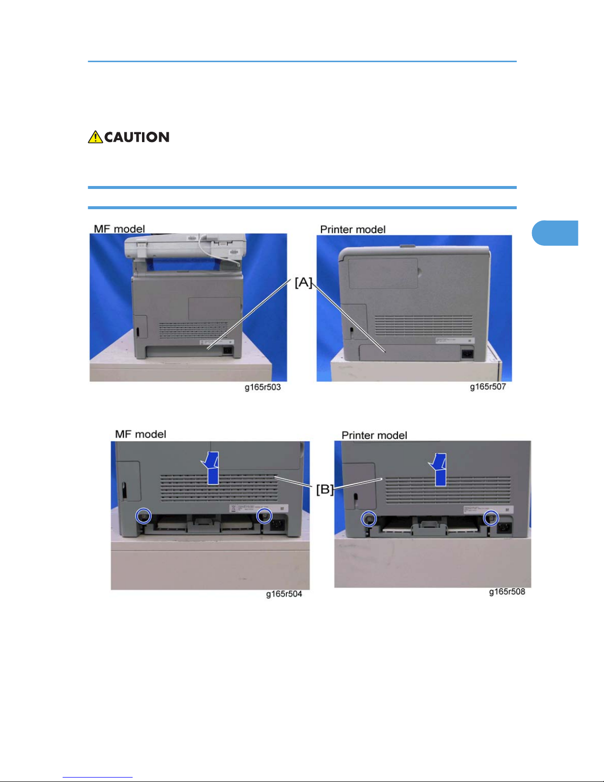
Rear Cover
1. Rear tray cover [A]
2. Rear cover [B] ( x 2)
Exterior Covers
19
3
Operation Panel
1. Open the top cover [A].
2. Open the front cover [B].
3. Front harness cover [C] ( x 1)
3. Replacement and Adjustment
20
3
4. Operation panel [D] ( x 1, x 1)
Right Cover
1. Rear cover (* Rear Cover)
2. Operation panel (*Operation Panel)
1. Right cover [A] ( x 4)
• Top front screw: M3x6, others: M4x6
Left Cover
1. Rear cover (* Rear Cover)
Exterior Covers
21
3
2. Operation panel (*Operation Panel)
1. Left cover [A] ( x 3, hook at arrow mark)
• Top front screw: M3x6, others: M4x6
Front Cover Unit
1. Rear cover (* Rear Cover)
2. Operation panel (* Operation Panel)
3. Transfer unit (*Transfer Unit)
4. Right cover (* Right Cover)
5. Cover link gear unit [A] ( x 2)
3. Replacement and Adjustment
22
3
6. Release the belt [B]
7. Front cover unit [C] ( x 4)
Exterior Covers
23
3
Laser Optics
• Turn off the main power switch and unplug the printer before beginning any of the procedures in this
section. Laser beams can cause serious eye injury.
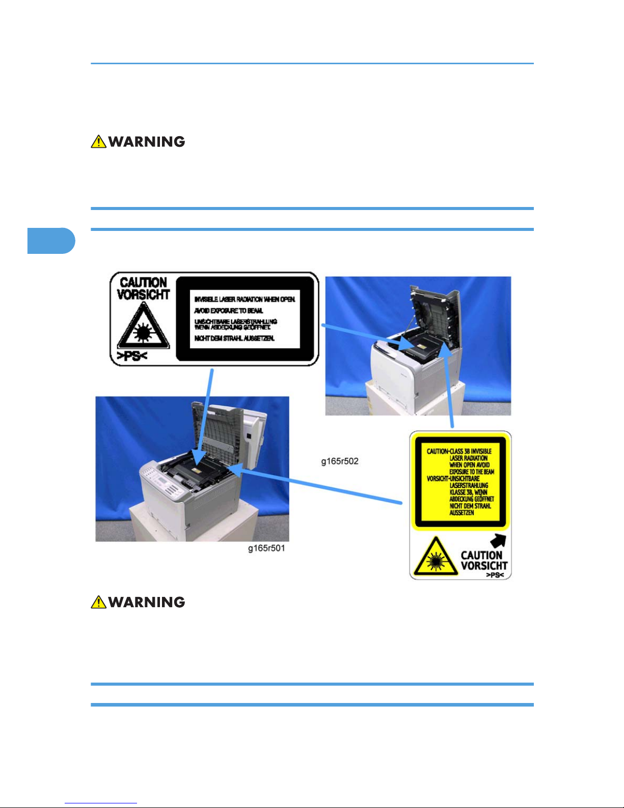
Caution Decal Locations
Caution decals are attached as shown below.
• Be sure to turn off the main power switch and disconnect the power plug from the power outlet before
beginning any disassembly or adjustment of the laser unit. This printer uses a class IIIb laser beam
with a wavelength of 655 nm and an output of 7 mW. The laser can cause serious eye injury.
Laser Optics Housing Unit
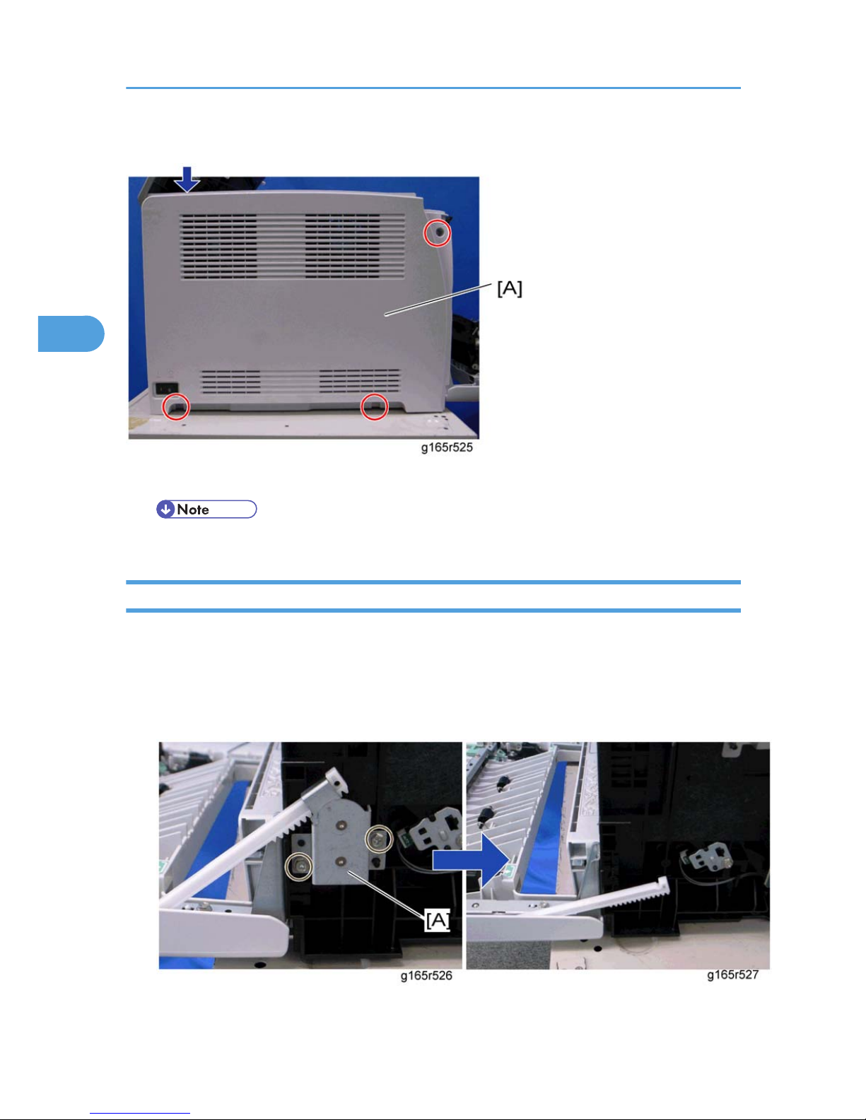
1. Rear cover (* Rear Cover)
3. Replacement and Adjustment
24
3
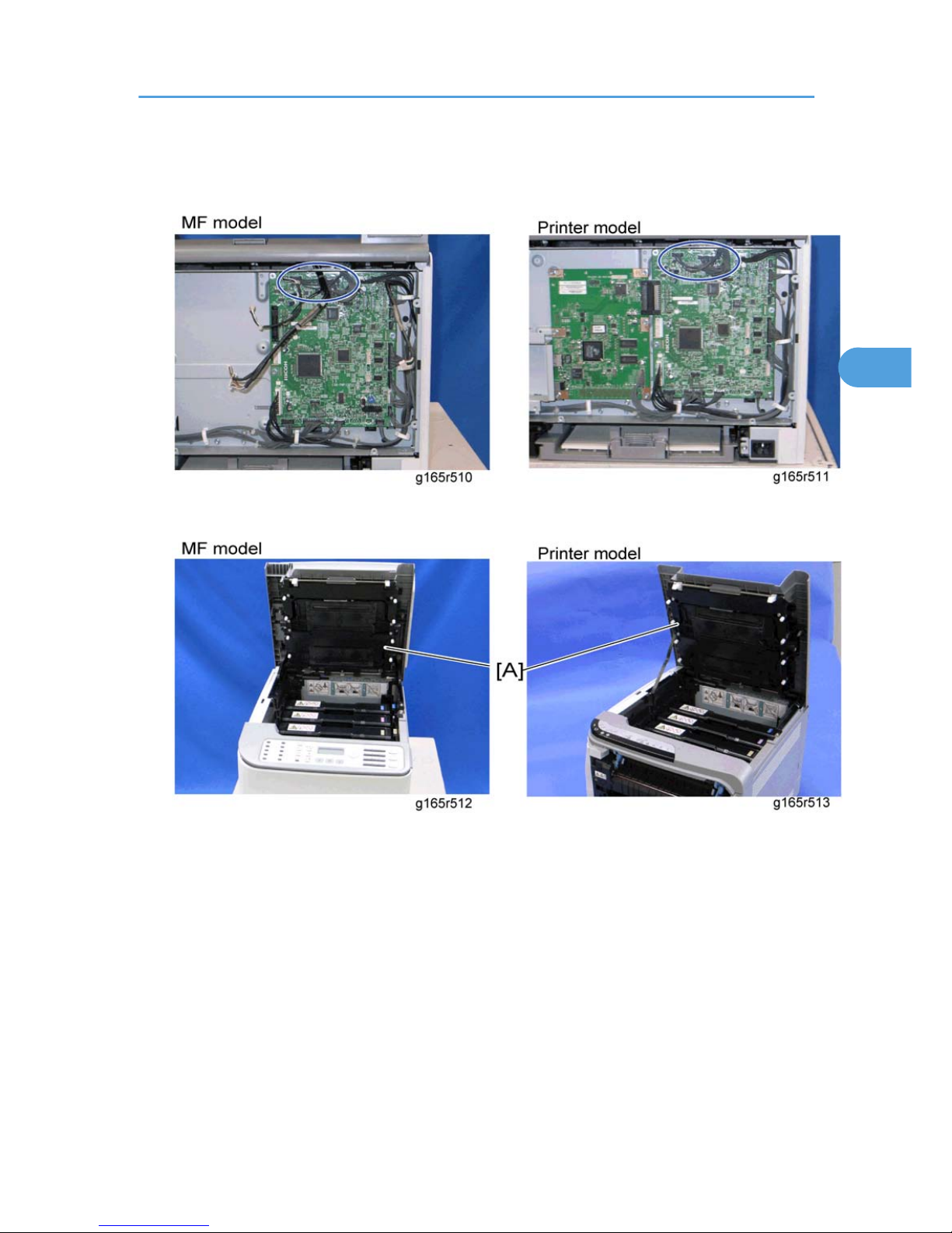
2. Controller box cover (* Controller Board)
3. MF model only: Remove the controller bracket (* EGB)
4. Disconnect the three harnesses from CN301, 302 and 303 on the EGB ( x 3).
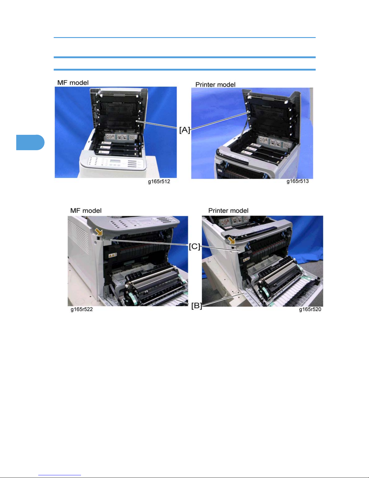
5. Open the top cover [A].
Laser Optics
25
3
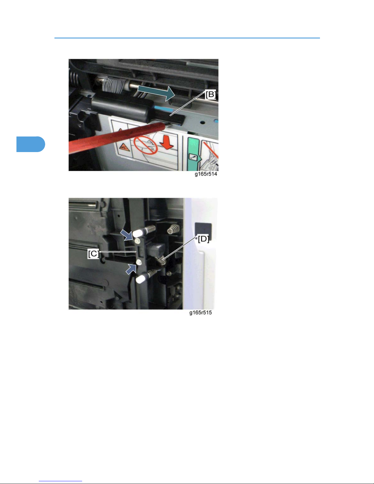
6. Lift up the hook [B] of the harness guide at the rear-left frame and slide the harness guide to the right.
7. Stoppers [C] ( x 2 each; left side and right side)
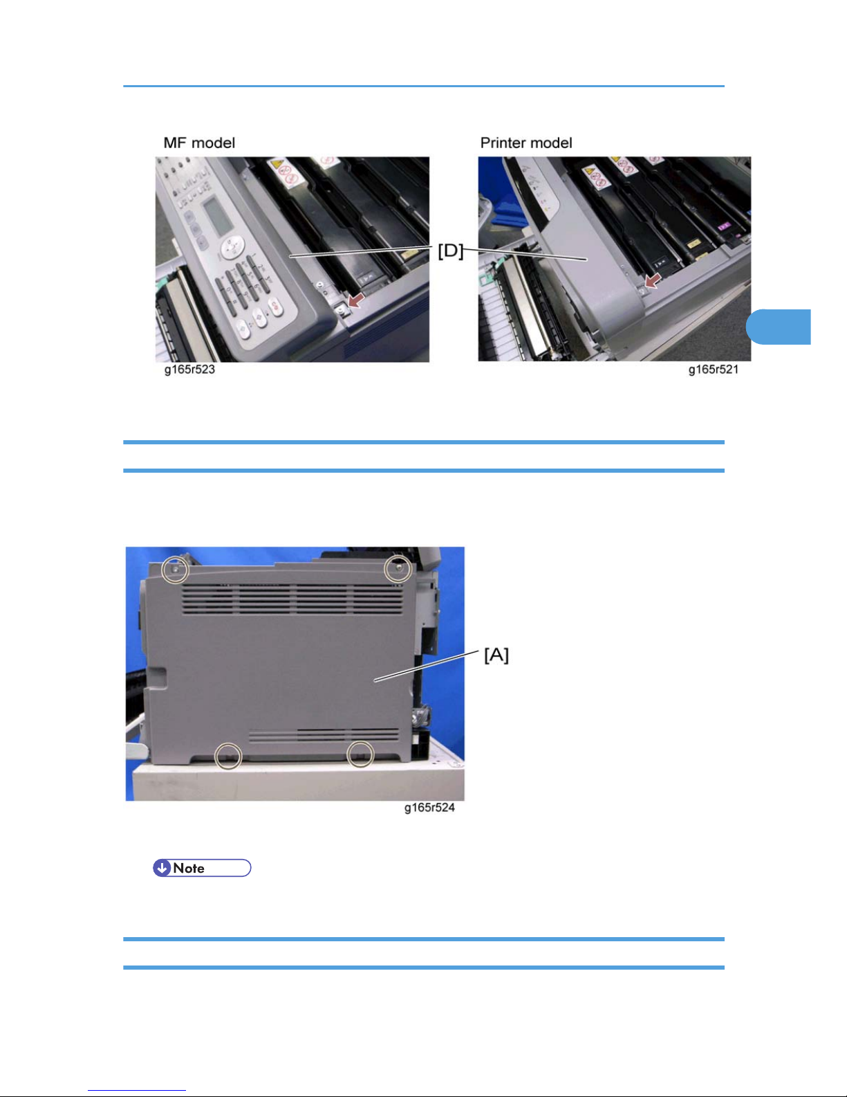
8. Remove the springs [D] (left side and right side).
3. Replacement and Adjustment
26
3
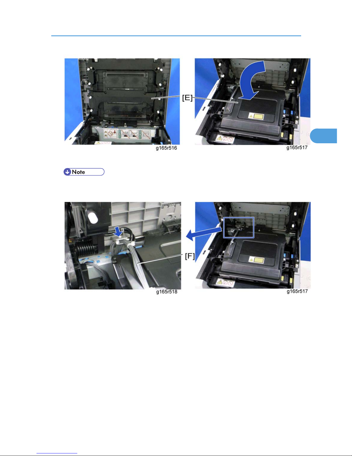
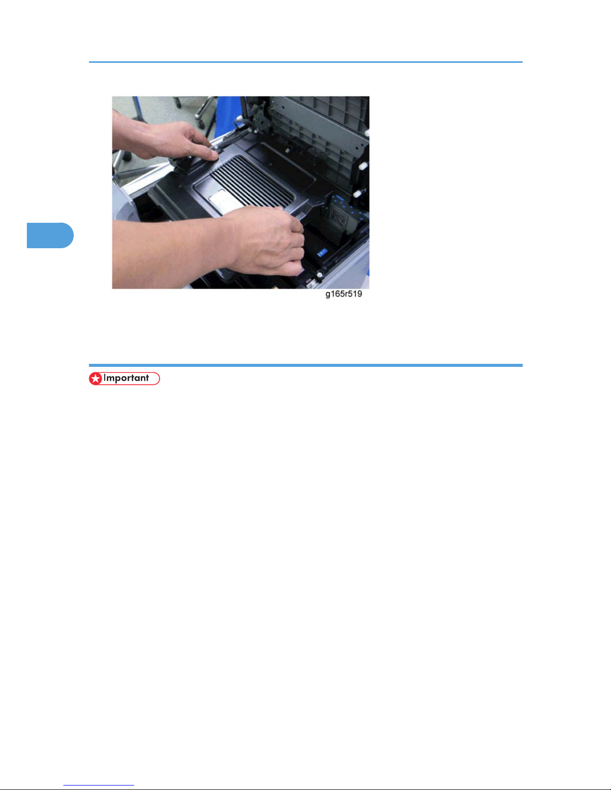
9. Remove the laser optics housing unit [E] from the top cover and place it on the main body.
• Always use two hands when carrying the laser optics housing unit. Be sure not to drop the laser
optics housing unit.
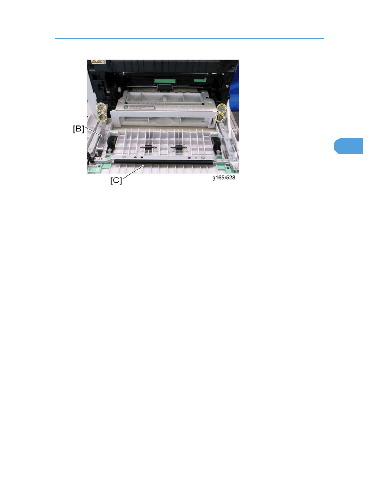
10. Take out the harnesses [F] ( x 1).
Laser Optics
27
3
11. Remove the laser optics housing unit.
After replacing the laser optics housing unit
• Do the following step 2 with the front cover of the machine open.
1. Open the front cover and turn on the machine.
2. Input the setting values for the laser optics housing unit.
• Printer model: "LSU Adjustment" in the "SP Mode 2" tab
• MF model: "LSU Adjustment" in the "Engine Maintenance" menu (MF model).
The settings are on a sheet of paper that comes with the laser optics housing unit.
3. Close the front cover.
4. Execute "Color Registration" in the "SP Mode 2" tab (printer model) or the "Engine Maintenance"
menu (MF model).
5. Adjust the registration settings for each tray and for the front and rear sides of the paper with the "SP
Mode 2" tab (printer model) or the "Engine Maintenance" menu (MF model) if necessary.
3. Replacement and Adjustment
28
3
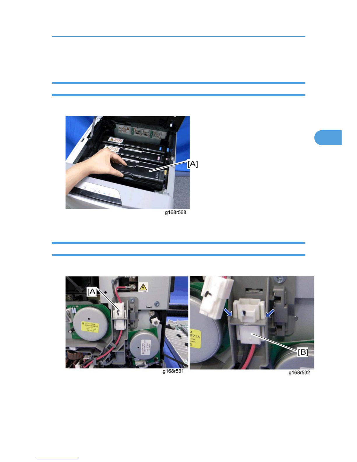
AIO Cartridge
AIO Cartridge (All In One Cartridge)
1. Open the top cover.
2. AIO cartridge [A]
Black AIO Motor
1. Left cover (* Left Cover)
2. Disconnect the fusing connector [A] and remove the fusing relay harness [B] (hooks).
AIO Cartridge
29
3
 Loading...