

Page 1
SERVICE MANUAL
(Machine code: C229)
Page 2

IMPORTANT SAFETY NOTICES
PREVENTION OF PHYSICAL INJURY
1. Before disassembling or assembling parts of the printer and peripherals, make
sure that the power cord is unplugged.
2. The wall outlet should be near the printer and easily accessible.
3. If any adjustment or operation check has to be made with exterior covers off or
open while the main switch is turned on, keep hands away from electrified or
mechanically driven components.
HEALTH SAFETY CONDITIONS
1. If you get ink in your eyes by accident, try to remove it with eye drops or flush
with water as first aid. If unsuccessful, get medical attention.
2. If you ingest ink by accident, induce vomiting by sticking a finger down your
throat or by giving soapy or strong salty water to drink.
OBSERVANCE OF ELECTRICAL SAFETY STANDARDS
1. The printer and its peripherals must be installed and maintained by a customer
service representative who has completed the training course on those models.
CAUTION
I
The RAM has a lithium battery which can explode if handled incorrectly.
Replace only with the same type of RAM. Do not recharge or burn this
battery. Used RAM's must be handled in accordance with local regulations.
ATTENTION
I
La carte RAM comporte une pile au lithium qui présente un risque
d'explosion en cas de mauvaise manipulation. Remplacer la pile
uniquement par une carte RAM identique. Ne pas recharger ni brûler cette
pile. Les cartes RAM usagées doivent être éliminées conformément aux
réglementations locales.
1
Page 3

SAFETY AND ECOLOGICAL NOTES FOR DISPOSAL
1. Dispose of replaced parts in accordance with local regulations.
2. Used ink and masters should be disposed of in an environmentally safe
manner and in accordance with local regulations.
3. When keeping used lithium batteries (from the main processing units) in order
to dispose of them later, do not store more than 100 batteries (from the main
processing units) per sealed box. Storing larger numbers or not sealing them
apart may lead to chemical reactions and heat build-up.
2
Page 4

IMPORTANT SAFETY NOTICES
PREVENTION OF PHYSICAL INJURY
1. Before disassembling or assembling parts of the printer and peripherals, make
sure that the power cord is unplugged.
2. The wall outlet should be near the printer and easily accessible.
3. If any adjustment or operation check has to be made with exterior covers off or
open while the main switch is turned on, keep hands away from electrified or
mechanically driven components.
HEALTH SAFETY CONDITIONS
1. If you get ink in your eyes by accident, try to remove it with eye drops or flush
with water as first aid. If unsuccessful, get medical attention.
2. If you ingest ink by accident, induce vomiting by sticking a finger down your
throat or by giving soapy or strong salty water to drink.
OBSERVANCE OF ELECTRICAL SAFETY STANDARDS
1. The printer and its peripherals must be installed and maintained by a customer
service representative who has completed the training course on those models.
CAUTION
I
The RAM has a lithium battery which can explode if handled incorrectly.
Replace only with the same type of RAM. Do not recharge or burn this
battery. Used RAM's must be handled in accordance with local regulations.
ATTENTION
I
La carte RAM comporte une pile au lithium qui présente un risque
d'explosion en cas de mauvaise manipulation. Remplacer la pile
uniquement par une carte RAM identique. Ne pas recharger ni brûler cette
pile. Les cartes RAM usagées doivent être éliminées conformément aux
réglementations locales.
1
Page 5

SAFETY AND ECOLOGICAL NOTES FOR DISPOSAL
1. Dispose of replaced parts in accordance with local regulations.
2. Used ink and masters should be disposed of in an environmentally safe
manner and in accordance with local regulations.
3. When keeping used lithium batteries (from the main processing units) in order
to dispose of them later, do not store more than 100 batteries (from the main
processing units) per sealed box. Storing larger numbers or not sealing them
apart may lead to chemical reactions and heat build-up.
2
Page 6

1 July, 1998 SPECIFICATIONS
1. OVERALL INFORMATION
1.1 SPECIFICATIONS
Configuration: Desktop
Master Processing: Digital with 400 dpi thermal head
Scanning (Pixel Density): 400 dpi CCD
Printing Process: Fully automatic stencil system, with one drum and
pressure cylinder system
Original Type: Sheet/Book
In Platen Mode: Document size:
Maximum 304.8 x 432 mm [12.0" x 17.0"]
Thickness: Less than 30 mm
Weight: Less than 10 kg
In ADF Mode: Document size:
Maximum 297 x 864 mm [11.6" x 33.8"]
Minimum 105 x 128 mm [4.2" x 5.1"]
Document weight:
52.3 - 104.7 g/m2[14 - 28 lb]
Overall
Information
ADF capacity:
30 sheets (using 20 lb or 80 g/m2 paper)
Reproduction Ratios: Inch versions Others
Full Size: 100% 100%
Reduction: 65% 71%
74% 82%
77% 87%
93% 93%
Enlargement: 121% 115%
129% 122%
155% 141%
Zoom: 50 - 200% (by 1%) in Platen mode
50 - 155% (by 1%) in ADF mode
Directional Magnification:
50 - 200% (by 1%)
Image Modes: Letter, Photo, Letter/Photo, Pencil, Tint
1-1
Page 7

SPECIFICATIONS 1 July, 1998
Printing Area:
(At 20 °C/ 65 % RH)
Metric size version models:
290 mm x 409 mm
Inch size version models:
290 mm x 419 mm [11.4" x 16.4"]
With optional A4 drum:
290 mm x 204 mm [11.4" x 8.0"]
Edge Margins: Leading edge:
10 mm (At the "0" position of Image Shift mode)
Trailing edge:
2 mm
Print Paper Size: Minimum: 70 mm x 148 mm [2.8" x 5.9"]
Maximum: 325 mm x 447 mm [12.7" x 17.6"]
Print Paper Weight: 47.1 g/m2 to 209.3 g/m2 [12.5 lb to 55.6 lb]
Printing Speed: 60, 75, 90, 105, 120 sheets/minute (5 steps)
Master Process Time: Platen mode:
Less than 15.5 seconds (A3 paper)
Less than 12 seconds (A4 paper)
ADF mode:
Less than 19.5 seconds (A3 paper)
Less than 16 seconds (A4 paper)
Master Eject Box Capacity: 60 masters / A3 size (Normal conditions)
Side Registration Adjustable
± 10 mm
Range:
Vertical Registration Adjustable
Range:
Inch size version models:
± 10 mm
Metric size version models:
± 15 mm
Paper Feed Table Capacity: 1000 sheets (80 g/m2 / 20 lb)
Paper Delivery Table Capacity: 1000 sheets (80 g/m2 / 20 lb)
Power Source: 110/120 V, 50/60 Hz: 2.7 A
220 - 240 V, 50/60 Hz: 1.5 A
Maximum Power Consumption: 110/120 V version: 285 W
220 - 240 V version: 280 W
1-2
Page 8

1 July, 1998 SPECIFICATIONS
Noise Emission:
(At operation position)
At 60 rpm printing speed: 57 dB
At 90 rpm printing speed: 60 dB
At 120 rpm printing speed: 64 dB
Weight: 94 kg [207 lb]
101 kg [222.7 lb] with ADF
Dimensions:
(Width x Depth x Height)
Trays closed: 625 mm x 650 mm x 574 mm
With ADF:
625 mm x 650 mm x 684 mm
Trays open: 1405 mm x 650 mm x 574 mm
With ADF:
1405 mm x 650 mm x 684 mm
Master Type: Thermal master roll type:
420 mm width, 110 m / roll
Yield:
200 masters/roll (at A3 size)
Max run length per master:
2,000 prints
Master Storage Conditions: Temperature:
-10 °C to 40 °C
Overall
Information
Humidity:
10% to 95% RH
Recommended maximum storage period:
One year after production date
* Avoid locations exposed to direct sunlight.
Ink Type 1000 ml cartridge type
Available colors:
Black, Red, Blue, Green, Brown
Ink Storage Conditions: Temperature:
-5 °C to 40 °C
(Optimum conditions: 15 °C to 25 °C)
Humidity:
10% to 95% RH
(Optimum conditions: 20% to 70% RH)
Recommended maximum storage period:
One year after production date
* Avoid locations exposed to direct sunlight.
1-3
Page 9

SPECIFICATIONS 1 July, 1998
Available Options
· A3 Drum
· A4 Drum
· Document Feeder
· Key Counter
· Memory Board (Editing Function)
· PC Controller
· Interface Board (Standard for the U.S.A and
European versions)
1-4
Page 10
1 July, 1998 GUIDE TO COMPONENTS AND THEIR FUNCTION
1.2 GUIDE TO COMPONENTS AND THEIR FUNCTION
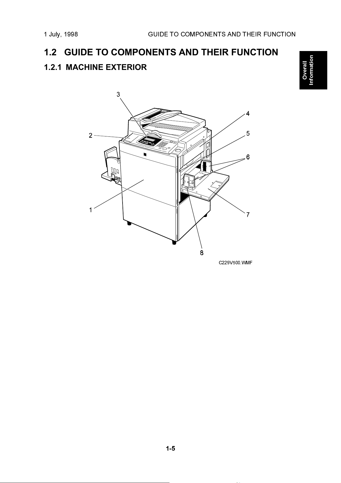
1.2.1 MACHINE EXTERIOR
Overall
Information
1. Front Door
2. Flip-up Cover
3. Operation Panel
4. Master Feed Unit
5. Paper Feed Tray Down key
6. Paper Feed Side/End
Plates
7. Paper Feed Tray
8. Paper Feed Side/End Plate
Knob
C229V500.WMF
Open for access to the inside of the
machine.
Open to access the Image Density key and
so on.
Operator controls and indicators are
located here.
Open the master feed unit when installing
the master.
Press to lower the paper feed tray.
Use to prevent paper skew.
Set paper on this tray for printing.
Use to move the side/end plates.
1-5
Page 11
MACHINE INTERIOR 1 July, 1998
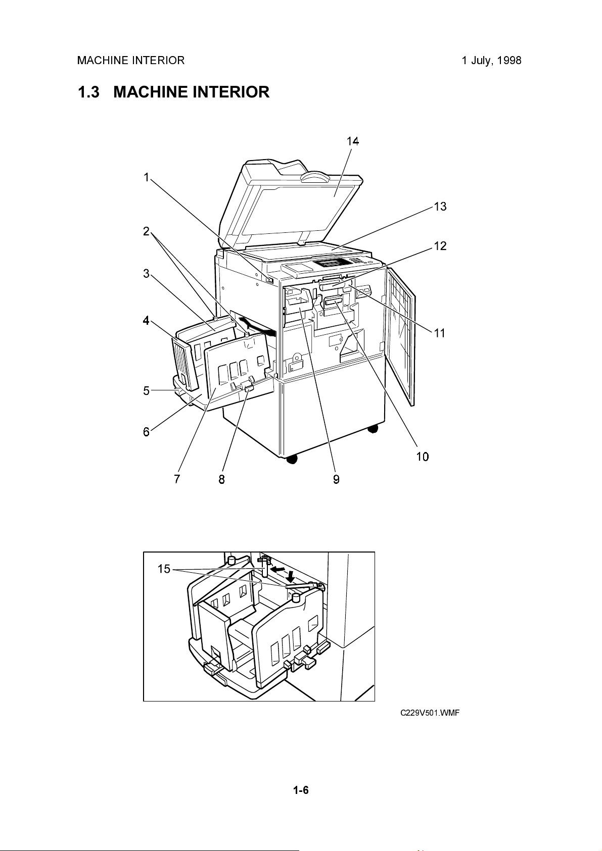
1.3 MACHINE INTERIOR
1-6
C229V501.WMF
Page 12

1 July, 1998 MACHINE INTERIOR
1. Main Switch
2. Paper Alignment Wing
Knobs
3. Paper Alignment Wings
4. Paper Delivery End Plate
5. Paper Delivery End Plate
Knob
6. Paper Delivery Tray
7. Paper Delivery Side Plates
8. Paper Delivery Side Plate
Knobs
9. Master Eject Unit Front
Handle E1
10. Ink Holder
11. Drum Unit Lock Lever B1
Use to turn the power on or off.
Use to lift or lower the paper alignment
wings.
Lift or lower the wings depending on the
paper type you use.
This plate aligns the leading edge of prints.
Use to move the end plate.
Completed prints are delivered here.
These plates align the prints on the paper
delivery tray.
Use to move the side plates.
Use to pull out the master eject unit.
Set the ink cartridge in this holder.
Lower to unlock and pull out the drum unit.
Overall
Information
12. Drum Unit
13. Exposure Glass (Contact
Glass)
14. Platen Cover
15. Trailing Edge Guides
The master is wrapped around this unit.
Position originals here face down for
printing.
Lower this cover over an original before
printing.
Swing out these guides when you use A4,
8
1/2
" x 11" sideways, or B5 lengthwise
paper.
1-7
Page 13
MACHINE INTERIOR 1 July, 1998
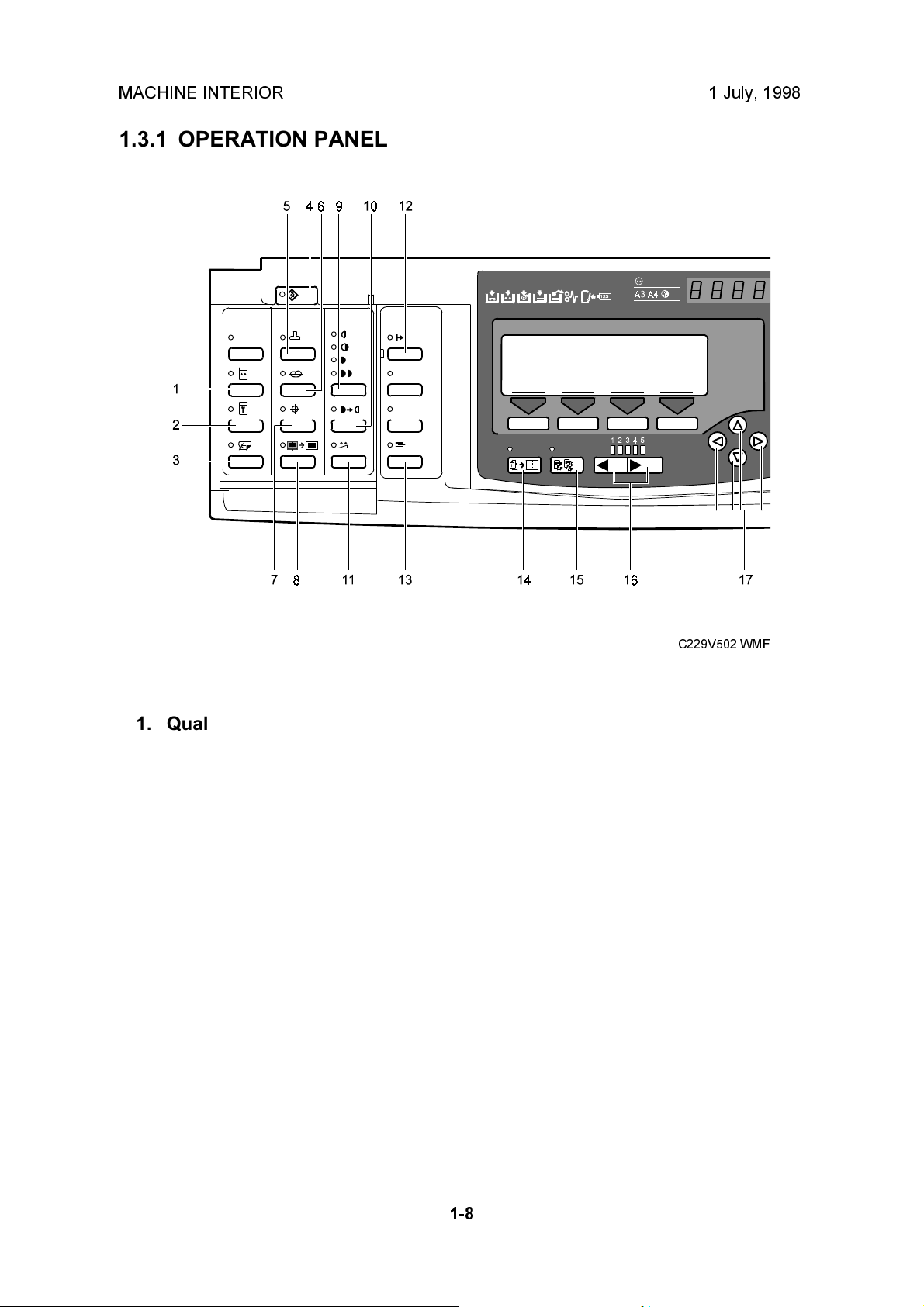
1.3.1 OPERATION PANEL
1. Quality Start key
2. Security key
3. Skip Feed key
4. User Tools key
Press to change the default
settings and conditions to meet
your requirements.
5. Stamp key
6. Make-up key
7. Overlay key
8. Edge Erase key
9. Image Density key
Press to make prints darker or
lighter.
C229V502.WMF
11. Economy Mode key
12. On Line key
13. Job Separator key
14. Combine key
Press to combine originals onto
one print.
15. Class key
Press to select All Class, Auto
Class, Manual Class, or Class
mode.
16. Speed keys
17. Scroll keys
Press to shift the image forward,
backward, right, or left.
10. Tint key
1-8
Page 14
1 July, 1998 MACHINE INTERIOR
Overall
Information
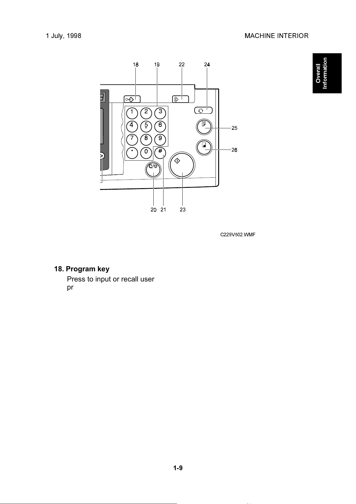
18. Program key
Press to input or recall user
programs.
19. Number keys
20. Clear/Stop key
While printing, press to stop the
machine.
21. Enter key
Use to enter data in selected
modes.
22. Clear Modes key
Press to clear the previously
entered job settings.
C229V502.WMF
23. Start key
Press to make a master.
24. Auto Cycle key
Use to process the master and
make prints at one stroke.
25. Proof key
Press to make a proof print.
26. Print key
Press to start printing.
1-9
Page 15
MACHINE INTERIOR 1 July, 1998
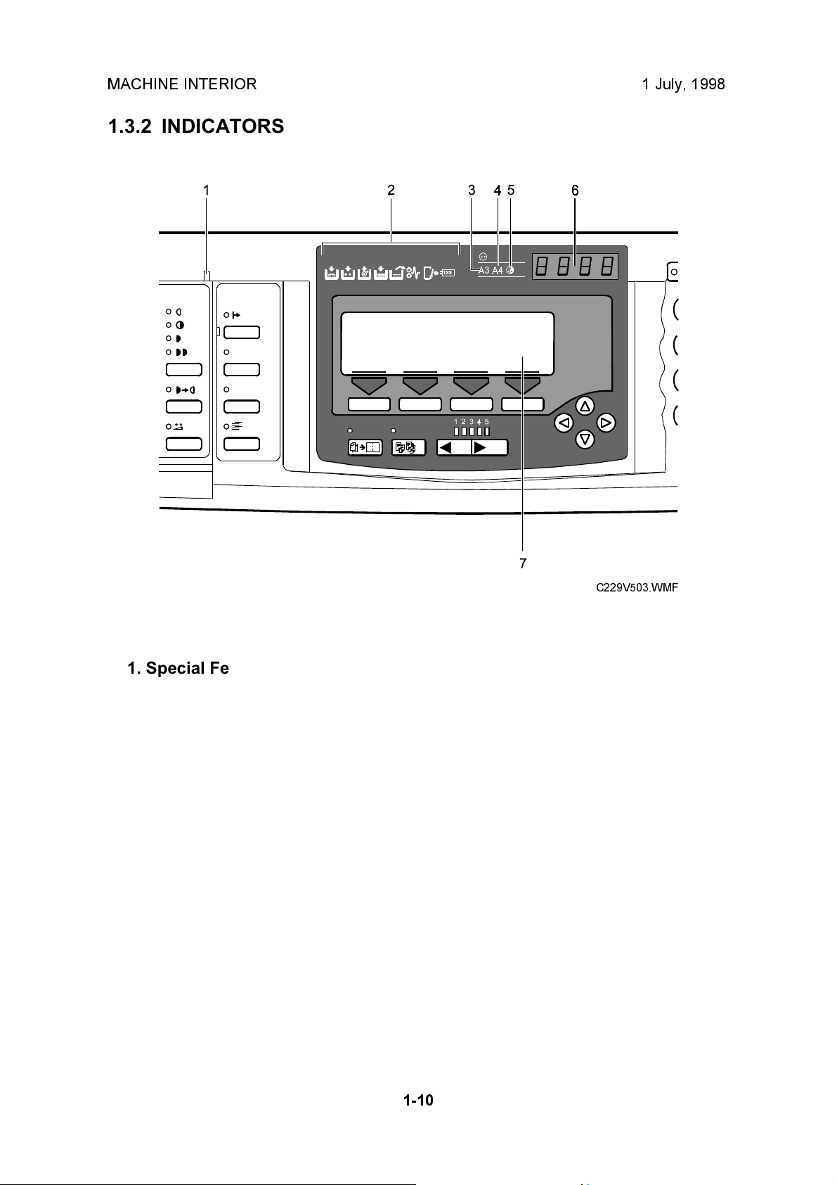
1.3.2 INDICATORS
1. Special Feature indicator
This indicator is lit when you
press keys under the flip-up
cover.
2. Monitors
The monitors light up when a
non-standard condition occurs
within the machine.
3. A3/11" x 17" Drum indicator
This indicator is lit when the A3,
11" x 17" drum unit is installed.
4. A4/81/2" x 11" Drum indicator
This indicator is lit when the A4,
81/2" x 11" drum unit is installed.
C229V503.WMF
5. Color Drum indicator
This indicator is lit when the color
drum unit is installed.
6. Counter
Displays the number of prints
entered. While printing, it shows
the number of prints remaining.
7. Panel Display
1-10
Page 16
1 July, 1998 PRINTING PROCESS OVERVIEW
1.4 PRINTING PROCESS OVERVIEW
2
3
Overall
Information
1
5
6
4
C229V008.WMF
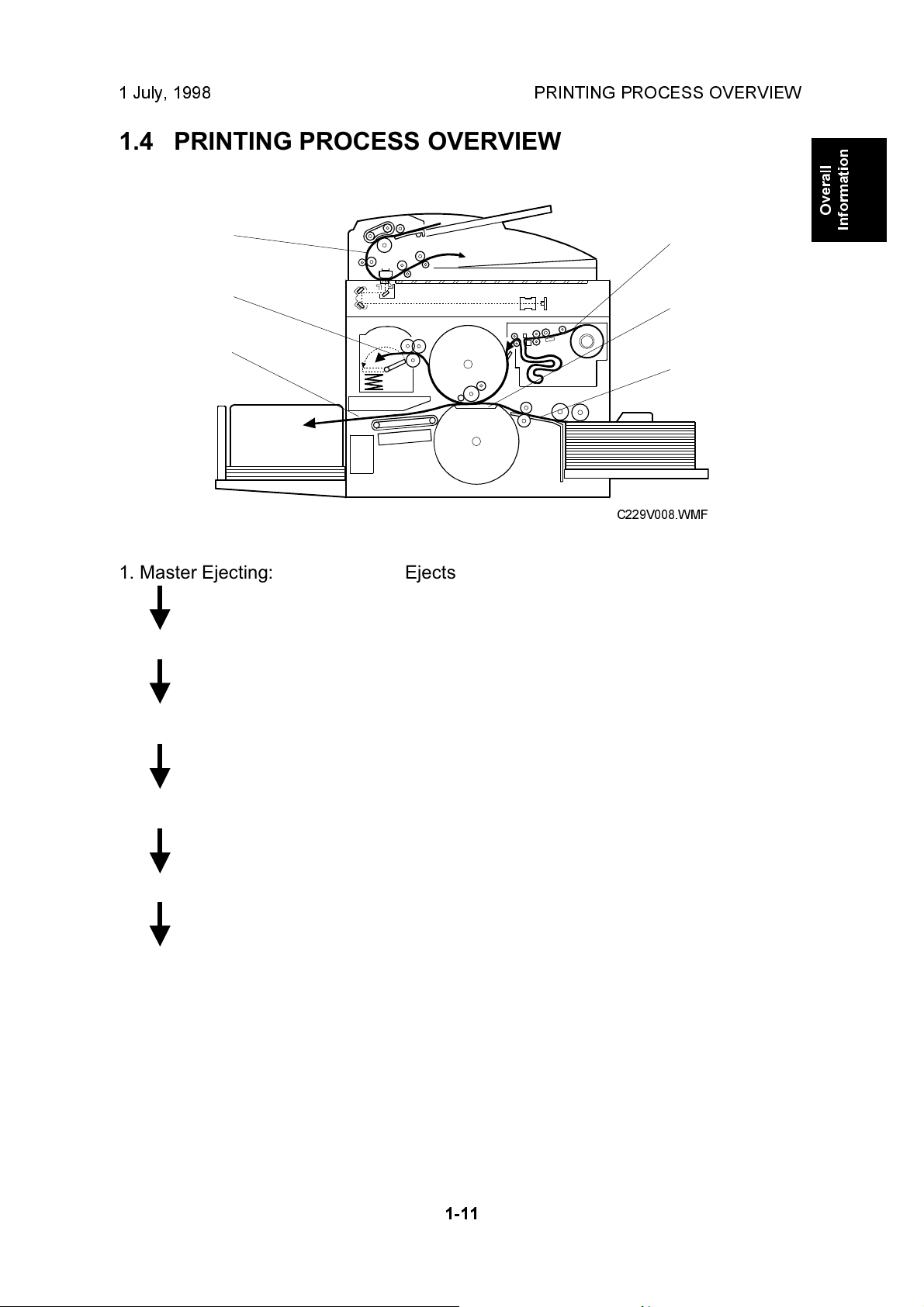
1. Master Ejecting: Ejects the used master wrapped around the drum
into the master eject box.
2. Scanning: Scans the original image with the CCD through the
mirrors and the lens.
3. Master Feeding: Converts the image signal read by the CCD into
digital signals and sends them to the thermal head to
develop the image on the master. The master then
wraps around the drum.
4. Paper Feeding: Sends paper to the drum section.
5. Printing: Presses the paper fed from the paper feed section
against the drum. This transfers ink to the paper
through the drum screen and the master.
6. Paper Delivering: Peels off the printed paper with the exit pawls and air
knife, and ejects the paper onto the paper delivery
table.
NOTE:
Some parts of the master eject, scanning, and master feeding processes
are carried out at the same time. Paper feeding also starts before the
master feeding process has finished.
1-11
Page 17
MECHANICAL COMPONENT LAYOUT 1 July, 1998
1.5 MECHANICAL COMPONENT LAYOUT
26
25
24
23
22
21
27
28
29
30
31 32 33
12
3
4
5
6
7
8
9
10
11
121314151617181920
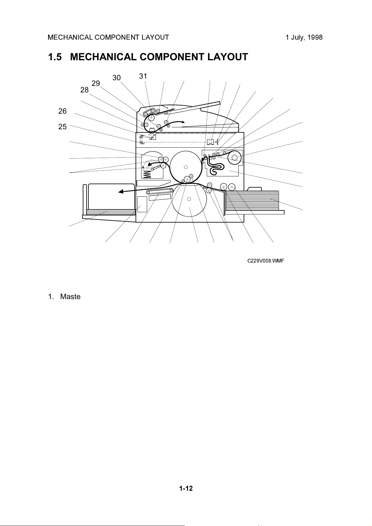
1. Master Feed Control Roller
2. Lens
3. CCD
4. SBU
5. Tension Roller
6. Platen Roller
7. Master Set Roller
8. Master Roll
9. Thermal Head
10. Master Buffer Duct
11. Paper Table
12. Paper Feed Roller
13. Paper Separation Roller
14. Registration Rollers
15. Doctor Roller
16. Pressure Cylinder
17. Ink Roller
C229V008.WMF
18. Idling Roller
19. Transport Belts
20. Job Separator Unit
21. Paper Delivery Table
22. Master Eject Rollers
23. Master Eject Box
24. Master Pick-up Roller
25. 2nd Scanner
26. 1st Scanner
27. DF Exposure Glass
28. 1st Transport Roller
29. 2nd Transport Roller
30. Original Feed Belt
31. Separation Roller
32. Pick-up Roller
33. Original Exit Roller
1-12
Page 18
1 July, 1998 ELECTRICAL COMPONENT LAYOUT
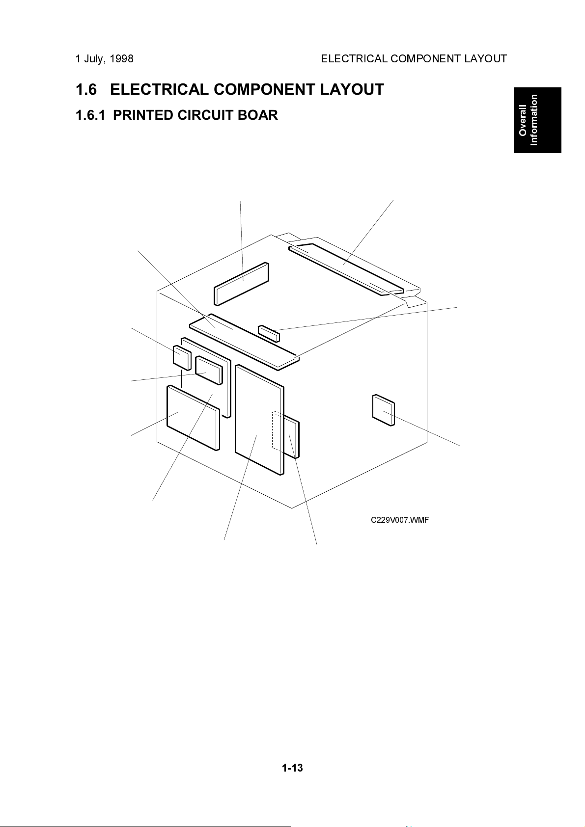
1.6 ELECTRICAL COMPONENT LAYOUT
1.6.1 PRINTED CIRCUIT BOARD LAYOUT
Overall
Information
10
9
8
7
11
1
2
3
6
C229V007.WMF
5
1-13
4
Page 19
ELECTRICAL COMPONENT LAYOUT 1 July, 1998
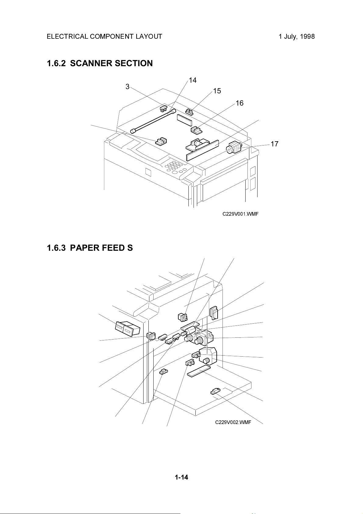
1.6.2 SCANNER SECTION
14
13
15
16
12
1.6.3 PAPER FEED SECTION
18
11
17
C229V001.WMF
19
20
34
33
32
31
30
29
28
1-14
C229V002.WMF
21
22
23
24
25
26
27
Page 20
1 July, 1998 ELECTRICAL COMPONENT LAYOUT
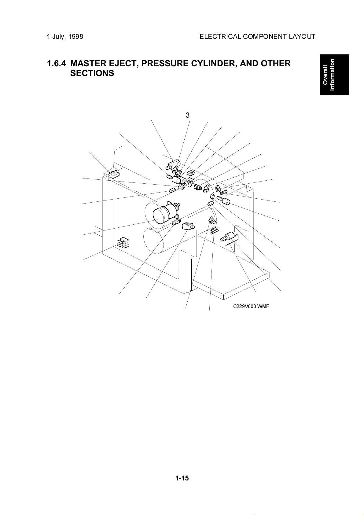
1.6.4 MASTER EJECT, PRESSURE CYLINDER, AND OTHER
SECTIONS
Overall
Information
59
58
57
56
35
36
55
54
37
53
38
39
52
40
41
42
43
44
45
46
47
48
49
50
51
C229V003.WMF
1-15
Page 21
ELECTRICAL COMPONENT LAYOUT 1 July, 1998
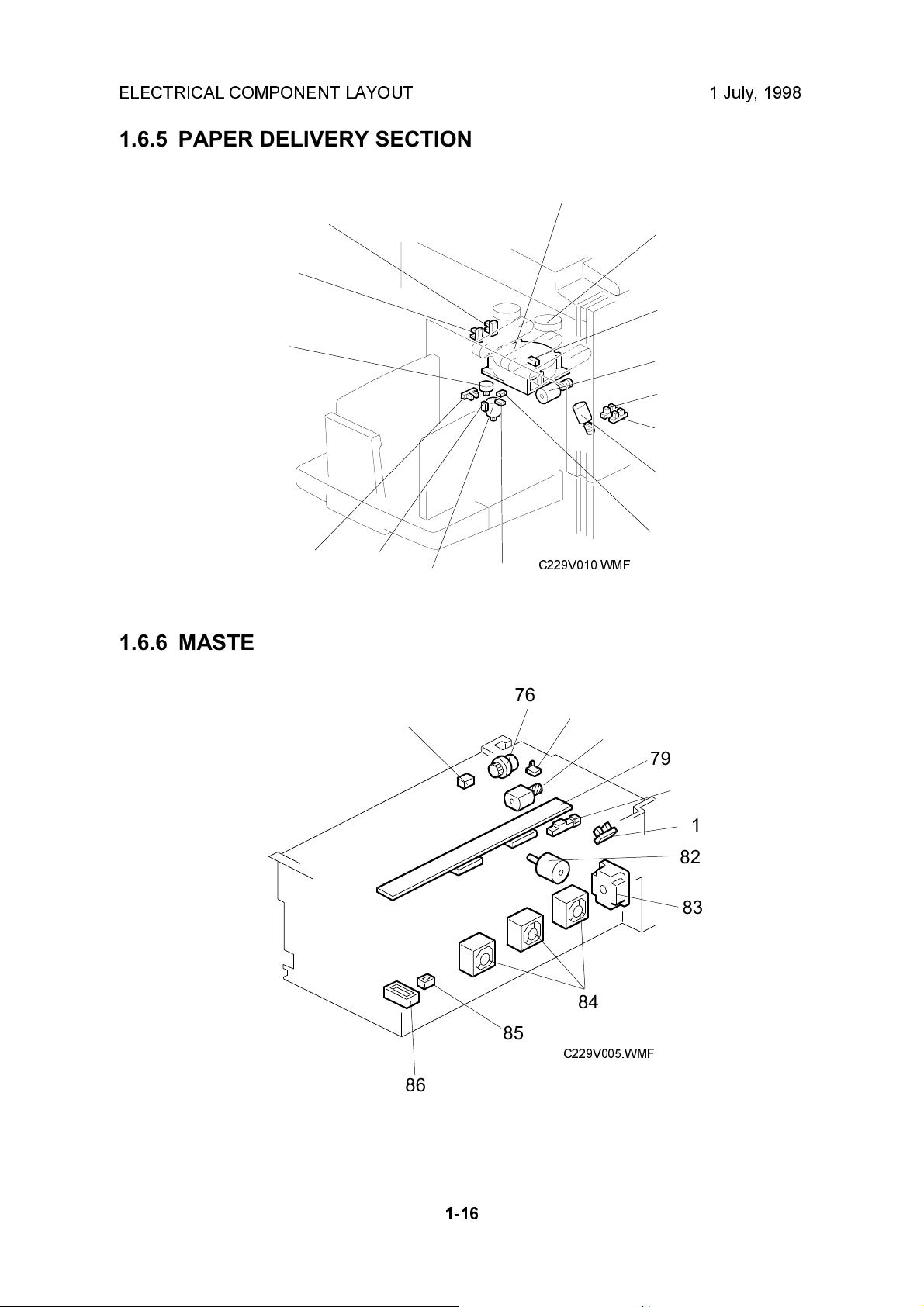
1.6.5 PAPER DELIVERY SECTION
60
74
73
72
71
70
1.6.6 MASTER MAKING UNIT
61
62
63
64
65
66
67
C229V010.WMF
6869
75
76
77
78
79
80
81
82
83
84
85
C229V005.WMF
86
1-16
Page 22
1 July, 1998 ELECTRICAL COMPONENT LAYOUT
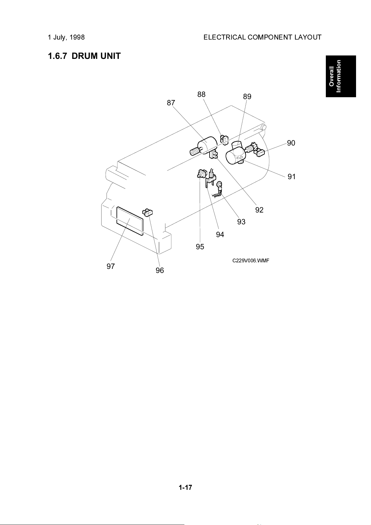
1.6.7 DRUM UNIT
88
87
89
90
91
92
Overall
Information
97
93
94
95
C229V006.WMF
96
1-17
Page 23
ELECTRICAL COMPONENT LAYOUT 1 July, 1998
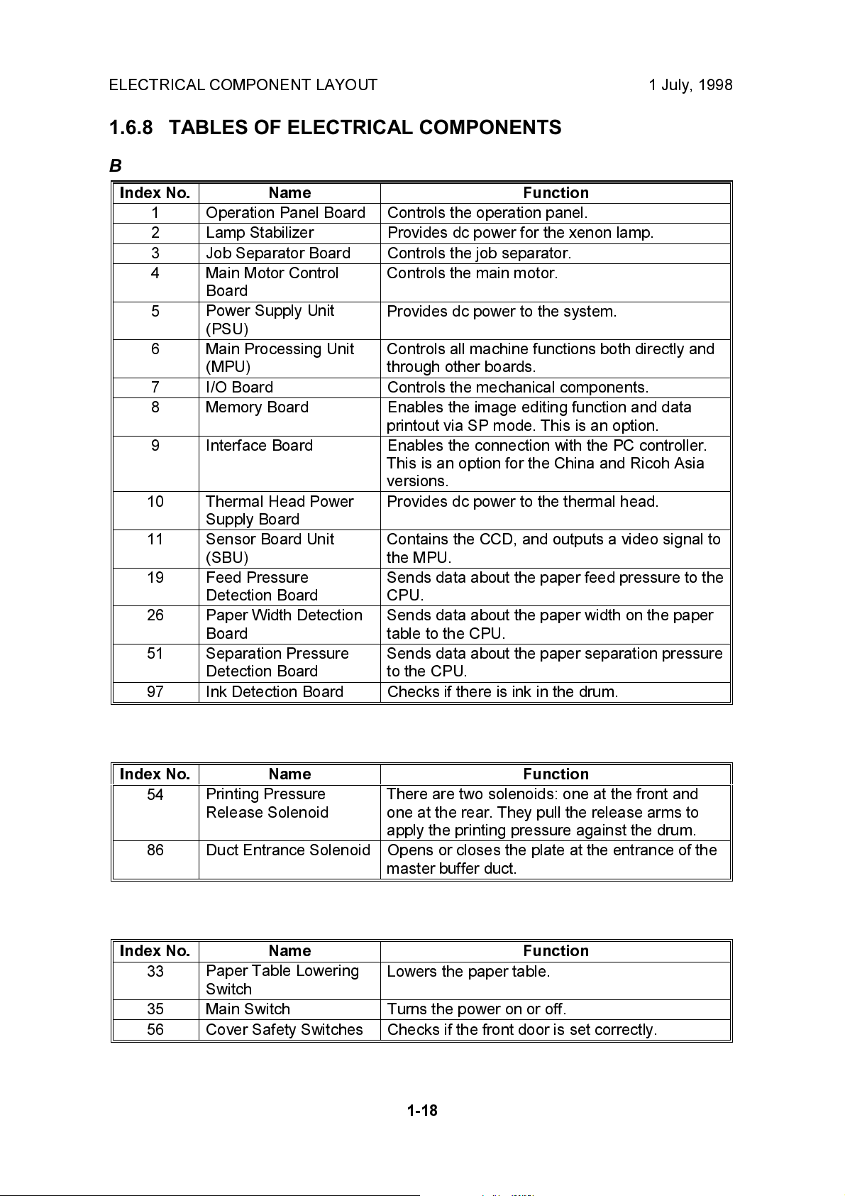
1.6.8 TABLES OF ELECTRICAL COMPONENTS
Boards
Index No. Name Function
1 Operation Panel Board Controls the operation panel.
2 Lamp Stabilizer Provides dc power for the xenon lamp.
3 Job Separator Board Controls the job separator.
4 Main Motor Control
Board
5
6 Main Processing Unit
7 I/O Board Controls the mechanical components.
8 Memory Board Enables the image editing function and data
9 Interface Board Enables the connection with the PC controller.
10 Thermal Head Power
11
19
26 Paper Width Detection
51 Separation Pressure
97 Ink Detection Board Checks if there is ink in the drum.
Power Supply Unit
(PSU)
(MPU)
Supply Board
Sensor Board Unit
(SBU)
Feed Pressure
Detection Board
Board
Detection Board
Controls the main motor.
Provides dc power to the system.
Controls all machine functions both directly and
through other boards.
printout via SP mode. This is an option.
This is an option for the China and Ricoh Asia
versions.
Provides dc power to the thermal head.
Contains the CCD, and outputs a video signal to
the MPU.
Sends data about the paper feed pressure to the
CPU.
Sends data about the paper width on the paper
table to the CPU.
Sends data about the paper separation pressure
to the CPU.
Solenoids
Index No. Name Function
54
86 Duct Entrance Solenoid Opens or closes the plate at the entrance of the
Printing Pressure
Release Solenoid
There are two solenoids: one at the front and
one at the rear. They pull the release arms to
apply the printing pressure against the drum.
master buffer duct.
Switches
Index No. Name Function
33
35 Main Switch Turns the power on or off.
56 Cover Safety Switches Checks if the front door is set correctly.
Paper Table Lowering
Switch
Lowers the paper table.
1-18
Page 24
1 July, 1998 ELECTRICAL COMPONENT LAYOUT
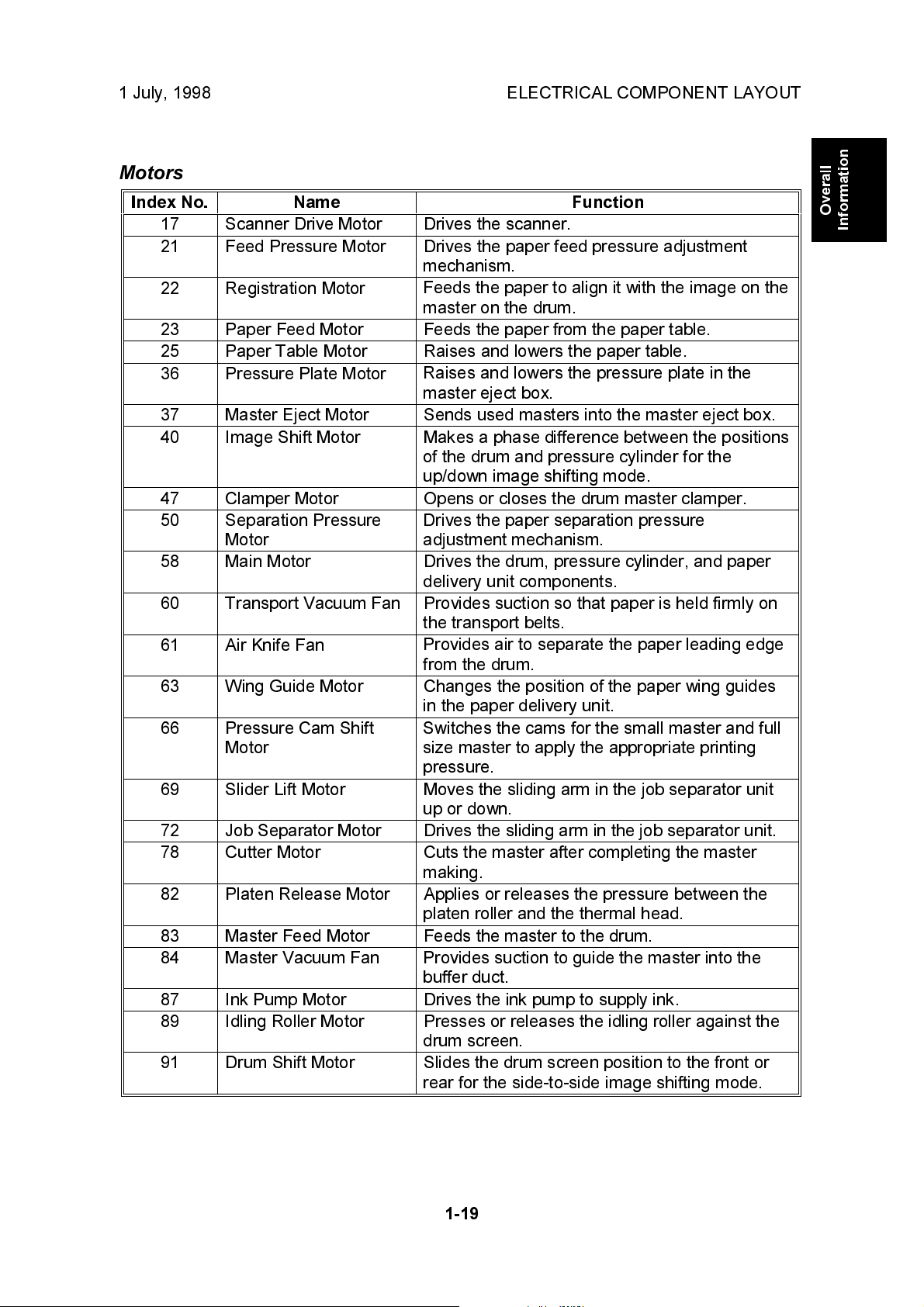
Motors
Index No. Name Function
17 Scanner Drive Motor Drives the scanner.
21 Feed Pressure Motor Drives the paper feed pressure adjustment
mechanism.
22 Registration Motor
Feeds the paper to align it with the image on the
master on the drum.
23 Paper Feed Motor Feeds the paper from the paper table.
25 Paper Table Motor Raises and lowers the paper table.
36 Pressure Plate Motor
Raises and lowers the pressure plate in the
master eject box.
37 Master Eject Motor Sends used masters into the master eject box.
40 Image Shift Motor Makes a phase difference between the positions
of the drum and pressure cylinder for the
up/down image shifting mode.
47 Clamper Motor Opens or closes the drum master clamper.
50
Separation Pressure
Motor
Drives the paper separation pressure
adjustment mechanism.
58 Main Motor Drives the drum, pressure cylinder, and paper
delivery unit components.
60 Transport Vacuum Fan Provides suction so that paper is held firmly on
the transport belts.
61 Air Knife Fan
Provides air to separate the paper leading edge
from the drum.
63 Wing Guide Motor Changes the position of the paper wing guides
in the paper delivery unit.
66 Pressure Cam Shift
Motor
Switches the cams for the small master and full
size master to apply the appropriate printing
pressure.
69 Slider Lift Motor Moves the sliding arm in the job separator unit
up or down.
72 Job Separator Motor Drives the sliding arm in the job separator unit.
78 Cutter Motor Cuts the master after completing the master
making.
82 Platen Release Motor Applies or releases the pressure between the
platen roller and the thermal head.
83 Master Feed Motor Feeds the master to the drum.
84 Master Vacuum Fan
Provides suction to guide the master into the
buffer duct.
87 Ink Pump Motor Drives the ink pump to supply ink.
89 Idling Roller Motor Presses or releases the idling roller against the
drum screen.
91 Drum Shift Motor Slides the drum screen position to the front or
rear for the side-to-side image shifting mode.
Overall
Information
1-19
Page 25
ELECTRICAL COMPONENT LAYOUT 1 July, 1998
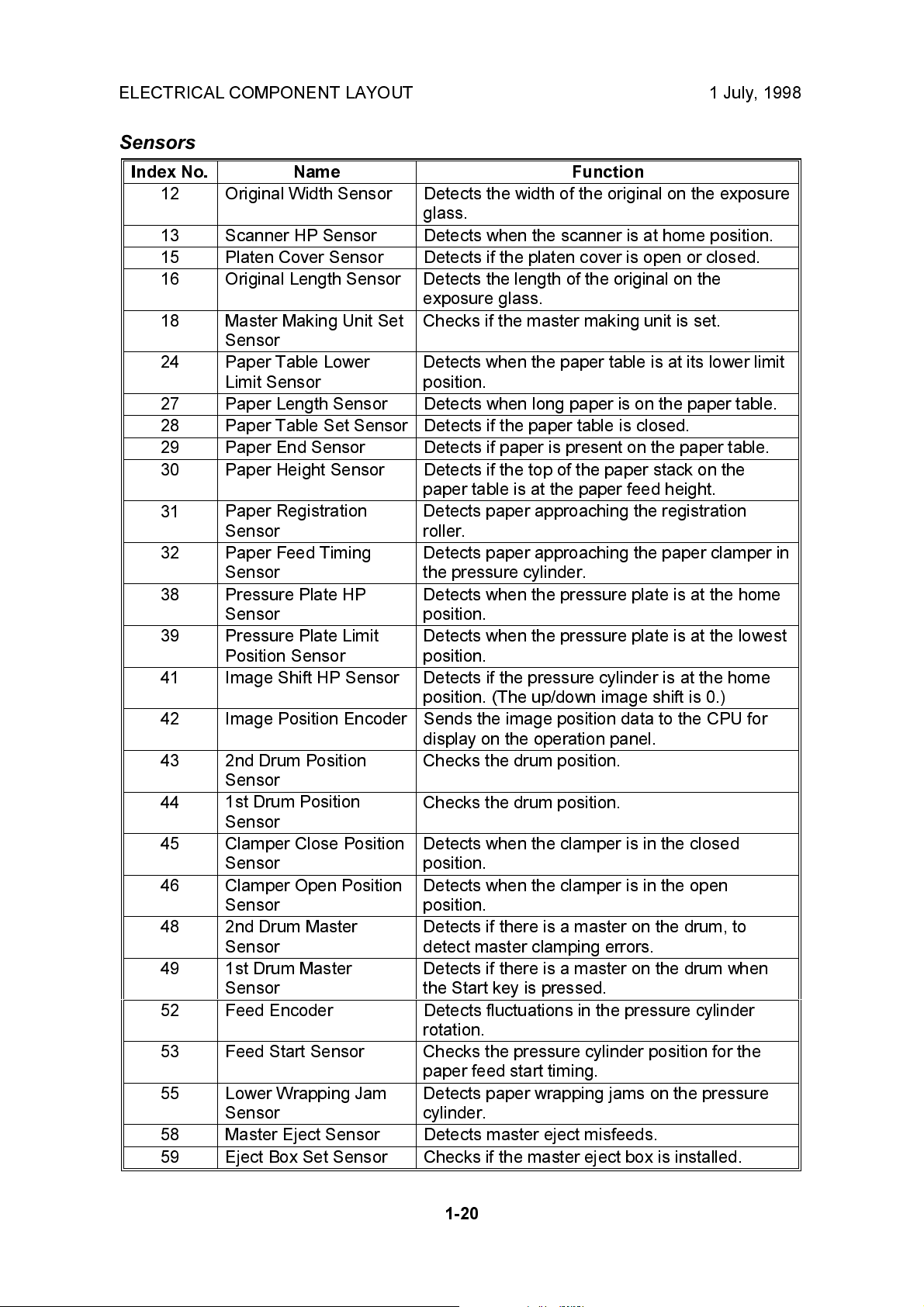
Sensors
Index No. Name Function
12 Original Width Sensor Detects the width of the original on the exposure
glass.
13 Scanner HP Sensor Detects when the scanner is at home position.
15 Platen Cover Sensor Detects if the platen cover is open or closed.
16 Original Length Sensor
18 Master Making Unit Set
Sensor
24 Paper Table Lower
Limit Sensor
27 Paper Length Sensor Detects when long paper is on the paper table.
28 Paper Table Set Sensor Detects if the paper table is closed.
29 Paper End Sensor Detects if paper is present on the paper table.
30 Paper Height Sensor Detects if the top of the paper stack on the
31
32 Paper Feed Timing
38 Pressure Plate HP
39 Pressure Plate Limit
41 Image Shift HP Sensor
42 Image Position Encoder Sends the image position data to the CPU for
43 2nd Drum Position
44
45 Clamper Close Position
46 Clamper Open Position
48
49 1st Drum Master
52 Feed Encoder Detects fluctuations in the pressure cylinder
53 Feed Start Sensor
55 Lower Wrapping Jam
58 Master Eject Sensor Detects master eject misfeeds.
59 Eject Box Set Sensor Checks if the master eject box is installed.
Paper Registration
Sensor
Sensor
Sensor
Position Sensor
Sensor
1st Drum Position
Sensor
Sensor
Sensor
2nd Drum Master
Sensor
Sensor
Sensor
Detects the length of the original on the
exposure glass.
Checks if the master making unit is set.
Detects when the paper table is at its lower limit
position.
paper table is at the paper feed height.
Detects paper approaching the registration
roller.
Detects paper approaching the paper clamper in
the pressure cylinder.
Detects when the pressure plate is at the home
position.
Detects when the pressure plate is at the lowest
position.
Detects if the pressure cylinder is at the home
position. (The up/down image shift is 0.)
display on the operation panel.
Checks the drum position.
Checks the drum position.
Detects when the clamper is in the closed
position.
Detects when the clamper is in the open
position.
Detects if there is a master on the drum, to
detect master clamping errors.
Detects if there is a master on the drum when
the Start key is pressed.
rotation.
Checks the pressure cylinder position for the
paper feed start timing.
Detects paper wrapping jams on the pressure
cylinder.
1-20
Page 26
1 July, 1998 ELECTRICAL COMPONENT LAYOUT
Index No. Name Function
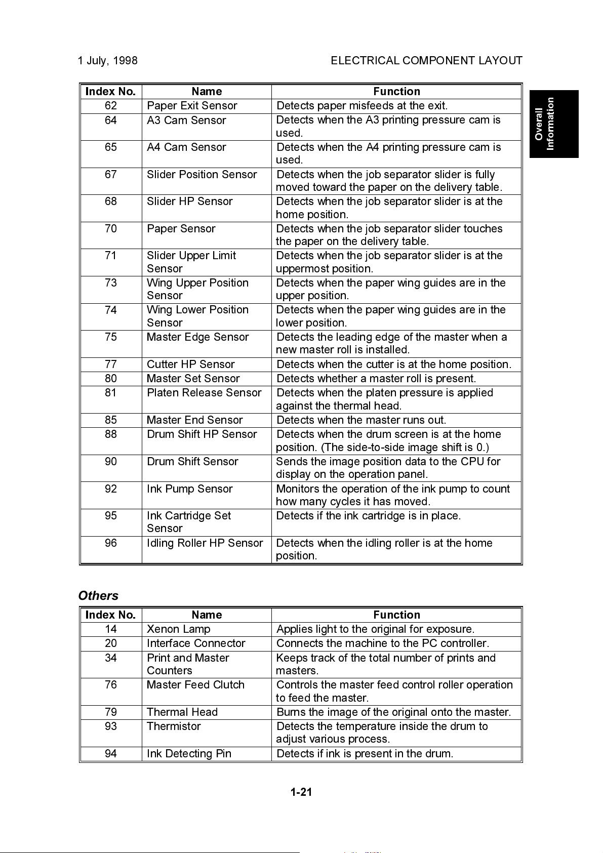
62 Paper Exit Sensor Detects paper misfeeds at the exit.
64 A3 Cam Sensor
Detects when the A3 printing pressure cam is
used.
65 A4 Cam Sensor Detects when the A4 printing pressure cam is
used.
67 Slider Position Sensor Detects when the job separator slider is fully
moved toward the paper on the delivery table.
68 Slider HP Sensor
Detects when the job separator slider is at the
home position.
70 Paper Sensor
Detects when the job separator slider touches
the paper on the delivery table.
71 Slider Upper Limit
Sensor
73 Wing Upper Position
Sensor
74
Wing Lower Position
Sensor
Detects when the job separator slider is at the
uppermost position.
Detects when the paper wing guides are in the
upper position.
Detects when the paper wing guides are in the
lower position.
75 Master Edge Sensor Detects the leading edge of the master when a
new master roll is installed.
77 Cutter HP Sensor Detects when the cutter is at the home position.
80 Master Set Sensor Detects whether a master roll is present.
81 Platen Release Sensor Detects when the platen pressure is applied
against the thermal head.
85 Master End Sensor Detects when the master runs out.
88 Drum Shift HP Sensor Detects when the drum screen is at the home
position. (The side-to-side image shift is 0.)
90 Drum Shift Sensor
Sends the image position data to the CPU for
display on the operation panel.
92 Ink Pump Sensor Monitors the operation of the ink pump to count
how many cycles it has moved.
95 Ink Cartridge Set
Detects if the ink cartridge is in place.
Sensor
96 Idling Roller HP Sensor
Detects when the idling roller is at the home
position.
Overall
Information
Others
Index No. Name Function
14 Xenon Lamp Applies light to the original for exposure.
20 Interface Connector Connects the machine to the PC controller.
34 Print and Master
Counters
76 Master Feed Clutch Controls the master feed control roller operation
79 Thermal Head Burns the image of the original onto the master.
93 Thermistor Detects the temperature inside the drum to
94 Ink Detecting Pin Detects if ink is present in the drum.
Keeps track of the total number of prints and
masters.
to feed the master.
adjust various process.
1-21
Page 27
DRIVE LAYOUT 1 July, 1998
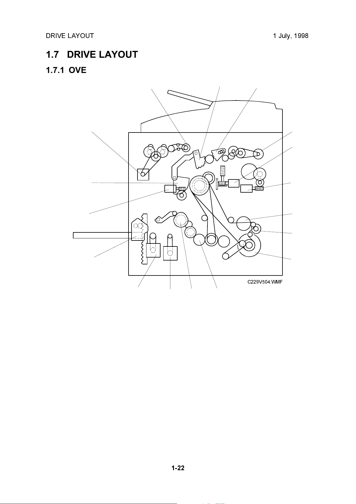
1.7 DRIVE LAYOUT
1.7.1 OVERVIEW
16
15
14
17
1
2
3
4
5
6
7
13
12
1. Clamper Opening Arm Sector
Gear (for the master eject position)
2. Master Pick-up Roller Sector Gear
3. Master Eject Motor
4. Image Shift Motor
5. Pressure Plate Motor
6. Exit Pawl Drive Cam Gear
7. Paper Delivery Unit Drive
Gear/Pulley
8. Main Motor
C229V504.WMF
11
10
9. Pressure Cylinder Drive Gear
(Including the Scissors Gear)
10. Registration Roller Lifting Cam Drive
Gear
11. Registration Motor
12. Paper Feed Motor
13. Paper Table Motor
14. Clamper Motor
15. Drum Guide
16. Master Feed Motor
17. Master Feed Clutch
9
8
1-22
Page 28

1 July, 1998 DRIVE LAYOUT
1.7.2 MAIN DRIVE
18
28
Overall
Information
26
25
27
24
23
19
20
21
22
C229V505.WMF
18. Drum
19. Pressure Cylinder
20. Printing Pressure Cam
21. Exit Pawl Drive Cam Gear
22. Main Motor
23. Printing Pressure Cam Drive Gear
24. Idler Gear/Pulley
25. Pressure Cylinder Drive Gear
(including the Scissors Gear)
26. Primary Gear/Pulley
27. Drum Drive Gear/Pulley
28. Image Shift Gear
1-23
Page 29
1 July, 1998 SCANNER AND OPTICS
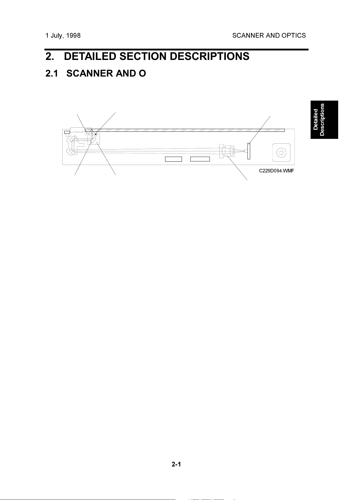
2. DETAILED SECTION DESCRIPTIONS
2.1 SCANNER AND OPTICS
2.1.1 OVERVIEW
[E]
[F]
The exposure lamp, a xenon lamp [A], illuminates the original. The 1st, 2nd, and
3rd mirrors, and a lens [B] reflect the image onto a CCD (Charge Coupled Device)
[C].
The 1st scanner [D] consists of the exposure lamp, a reflector [E], and the 1st
mirror [F].
A DC power supply energizes the exposure lamp to avoid uneven light intensity
when the 1st scanner moves in the sub-scan direction. The entire exposure lamp
surface is frosted to ensure even exposure in the main scan direction.
The reflector reflects light with almost equal intensity, to reduce shadows on pasted
originals.
[A]
[D]
[C]
C229D094.WMF
[B]
Detailed
Descriptions
2-1
Page 30
SCANNER AND OPTICS 1 July, 1998
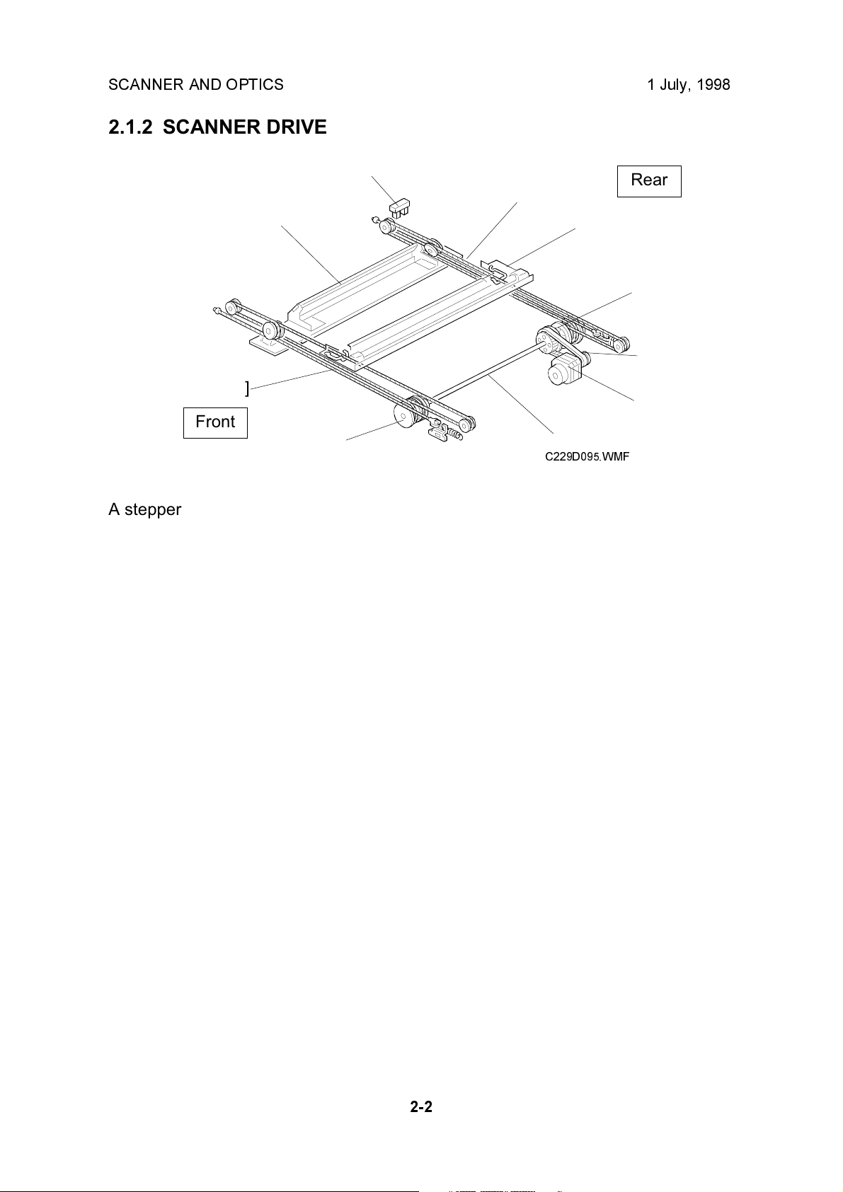
2.1.2 SCANNER DRIVE
[H]
Rear
[G]
[C]
[B]
[E]
[D]
[G]
[A]
Front
[E]
[F]
C229D095.WMF
A stepper motor drives the scanner. The scanner drive motor [A] drives the 1st and
2nd scanners [B, C] through the timing belt [D], scanner drive pulley [E], scanner
drive shaft [F], and two scanner wires [G].
- Book mode -
The scanner drive board controls and operates the scanner drive motor. In full size
mode, the 1st scanner speed is 42.33 mm/s during scanning. The 2nd scanner
speed is half that of the 1st scanner.
In reduction or enlargement mode, the scanning speed depends on the
magnification ratio (M: 0.50 to 2.00). The returning speed is always the same, in
both full size and magnification modes. Changing the scanner drive motor speed
changes the image length in the sub-scan direction. Image processing on the MPU
board accomplishes reduction and enlargement in the main scan direction.
SP6-011-1 changes the motor speed and therefore adjusts the magnification ratio
in the sub-scan direction.
- ADF mode -
During scanning, the scanners are always in their home positions (when the
scanner H.P sensor [H] detects the 1st scanner). The ADF motor feeds the original
through the ADF. In reduction/enlargement mode, changing the ADF motor speed
changes the image length in the sub-scan direction. Magnification in the main scan
direction is done on the MPU board, in the same manner as book mode.
SP6-011-2 changes the ADF motor speed and therefore adjusts the magnification
ratio in the sub-scan direction.
2-2
Page 31

1 July, 1998 SCANNER AND OPTICS
2.1.3 ORIGINAL SIZE DETECTION IN PLATEN MODE
[B]
Detailed
Descriptions
[A]
[C]
C229D096.WMF
C229D120.WMF
[C]
C229D116.WMF
In Platen mode, the size of paper on the paper table usually determines the image
reading area for the original. If Reduction or Enlargement mode is used, the
magnification ratio affects the image reading area.
However, for Auto Magnification, Image Rotation, or Image Repeat modes
combined with Platen mode, the original width [A] and length [B] sensors detect the
original size.
The sensors for original size detection are in the optics cavity. There are four
reflective sensors in the 115V machines, and six reflective sensors in the 220/240V
machines.
2-3
Page 32

SCANNER AND OPTICS 1 July, 1998
The platen cover sensor [C] or the DF position sensor [D] informs the main CPU of
the original size when the platen is about 15 cm above the exposure glass. At this
time, only the sensors located underneath the original receive the reflected light
and switch on. The other sensors remain off. The main CPU can recognize the
original size from the number of activated sensors.
Original Size Length Sensors Width Sensors
A4/A3 version LT/DLT version L1 L2 L3 L4 S1 S2
A3 11" x 17" O O O O O O
B4 10" x 14" O O O O O X
F4 8
A4L 8
B5L - O X X X X X
A4S 11" x 8
B5S - X X X X O X
1/2
" x 14" (8" x 13") O O O X X X
1/2
" x 11" O O X X X X
1/2
"XXXXOO
NOTE:
1) O: On (Paper Present), X: Off
2) The length sensors L3 and L4 are only used in the 220/240V machines.
The above table shows the sensor output for each original size. A message will
appear in the operation panel display for other combinations.
2-4
Page 33

1 July, 1998 IMAGE-PROCESSING
2.2 IMAGE-PROCESSING
2.2.1 OVERVIEW
SBU
CCD
Detailed
Descriptions
Thermal
Head
IPU
Memory
Board
(Option)
MPU
C229D501.WMF
The CCD converts the light reflected from the original into an analog signal. The
CCD line has 5,000 pixels and the resolution is 400 dpi (15.7 lines/mm).
After the above process, the A/D converter built into the SBU transforms the analog
signals into 8-bit signals. This assigns a value to each pixel from a scale of 256
grades. Then, the digitized image data goes to the MPU board.
The image data then goes to the IPU (Image-processing Unit) IC on the MPU
board, which carries out the following processes on the image data:
1. Auto shading
2. Filtering (MTF and smoothing)
3. Magnification
4. Binary processing
2-5
Page 34

IMAGE-PROCESSING 1 July, 1998
2.2.2 AUTO BACKGROUND CORRECTION
[A]
C229D097.WMF
Auto background correction mode can be used in Photo/Letter, Photo, and Tint
modes. The default setting does not allow the user to select auto background
correction mode. (Use SP 2-31 to enable this mode.)
Auto background correction prevents the background of an original from appearing
on copies.
While scanning the original, the background density detection area [A] is also
scanned. This area [A] is a narrow strip at the start of the main scan line, as shown.
As the scanner scans down the page, the IPU on the MPU detects the peak white
level for each scan line, within this narrow strip only. From this peak white level, the
IPU determines the reference value for the A/D conversion for the scan line. The
IPU then sends the reference value to the reference controller on the SBU.
When an original with a gray background is scanned, the density of the gray area
is the peak white level density. Therefore, the original background will not appear
on copies. This feature corrects any changes in background density down the
page, because peak level data is taken for each line scanned.
2-6
Page 35

1 July, 1998 IMAGE-PROCESSING
2.2.3 AUTO SHADING
C229D504.WMF
There are two auto shading methods: black level and white level correction. Auto
shading corrects errors in the signal level for each pixel.
Detailed
Descriptions
- Black Level Correction -
The CPU reads the black dummy data from one end of the CCD signal (64 pixels
are blackened at the end) and takes an average of the black dummy data. Then,
the CPU deletes the black level value of each image pixel.
- White Level Correction -
The machine reads a reference waveform from the white plate, before scanning the
original. The average of the white video level for each pixel is stored as the white
shading data in the IPU.
The IPU chip corrects the video signal information for each pixel obtained during
image scanning.
2-7
Page 36

IMAGE-PROCESSING 1 July, 1998
2.2.4 FILTERING AND MAIN SCAN MAGNIFICATION/REDUCTION
Overview
Filtering and main scan magnification process the image data after auto shading.
However, to reduce moire in the image, the processing order depends on the
reproduction ratio, as follows:
1) Reduction and Full size
Main Scan Reduction ® Filtering
2) Enlargement
Filtering ® Main Scan Magnification
Filtering
The MTF and smoothing filters are software filters that enhance the desired image
qualities of the selected original mode.
The MTF filter, used in all modes except Tint mode (which uses the smoothing
filter), sharpens the image.
SP6-082 adjusts the filter strengths for MTF mode.
The diagram below shows how the number stored in the SP mode afects the
strength of the filter.
NOTE:
1) Do not set the filter strength number to 1. Abnormal images may result.
2) The smoothing filter strength is not adjustable.
11 8 2
2-8
C229D505.WMF
Page 37

1 July, 1998 IMAGE-PROCESSING
Main Scan Magnification/Reduction
Detailed
Descriptions
C229D506.WMF
The IPU chip handles reduction and enlargement in the main scan direction.
NOTE:
Changing the scanner speed accomplishes reduction and enlargement in
the sub-scan direction.
When making a copy using the ADF, the magnification circuit creates a mirror
image. This is because the scanning starting position in the main scan direction is
at the other end of the scan line in ADF mode (as compared with platen mode). In
platen mode, the original is placed face down on the exposure glass, and the
corner at [A] is at the start of the main scan. The scanner moves down the page. In
ADF mode, the ADF feeds the leading edge of the original to the DF exposure
glass, and the opposite top corner of the original is at the main scan start position.
To create the mirror image, the CPU stores the main scan line data in the LIFO
(Last In First Out) memory on the MPU, from the last pixel. When loading the main
scan line data from the LIFO memory, the CPU loads the first pixel of the main
scan line.
2-9
Page 38

IMAGE-PROCESSING 1 July, 1998
2.2.5 BINARY PROCESSING
In the IPU chip, the 8-bit data is converted into 1-bit data for black or white pixels.
The binary processing for the letter mode is different from that for the photo mode
and the letter/photo mode as follows:
1) Letter mode: Binary processing
2) Letter/Photo mode: Binary processing
3) Photo mode: Binary processing + error diffusion + dithering
These processes are used as follows.
- Binary Processing with Gamma Curve Compensation -
This process converts each video signal level from 8-bit to 1-bit (black and white
image data) in accordance with a threshold value.
The threshold value changes based on a compensation curve (Gamma curve)
which corresponds to selected image settings. For example, if a darker image is
selected, a compensation curve, which converts each pixel value to a higher
number, is selected. This ensures accurate generation of the gray scale from black
to white.
- Error Diffusion - (Photo mode only)
The error diffusion process reduces the difference in contrast between light and
dark areas of a halftone image. This process corrects each pixel using the
difference between it and surrounding pixels. It then compares the corrected pixels
with the error diffusion matrix.
- Dithering - (Photo mode only)
Dithering compares each pixel with a pixel in the dither matrix. Several matrixes
are available, to increase or decrease the detail on the copy.
2-10
Page 39

1 July, 1998 IMAGE-PROCESSING
2.2.6 OPTIONAL MEMORY BOARD
The optional memory board, or editing function board, has 4-Mbyte RAM, which
corresponds to the amount of memory required for an A3 original. This enables the
following image editing functions.
- Memory Combine Mode -
Combined images of 4, 8, or 16 originals are printed on the same sheet of paper.
- Overlay -
Overlay merges two different originals onto the same sheet of paper.
- Stamp Printing Mode -
This mode enables stamping modes such as, the date, page number, preset
message, and user custom stamps.
Detailed
Descriptions
- Make-up Printing Mode -
The user makes command sheets to specify how various areas of the original will
be processed. The user must be sure to scan the command sheets before the
original. The image-processing chip in the MPU modulates the image data for the
command sheet and then stores the modulated command data on the memory
board.
The image data for the original is also converted and modulated. The MPU edits
the modulated image data, the stored command area data, and the background
pattern.
Positive/Negative can be used with this mode.
- Report Print Mode -
This mode prints the following data:
· User reports
· Jam and error counter data
· The number of people in each class set by the user
· Number of prints and masters for each user code account
· SP mode data for service
- Image Rotation Mode -
When the orientation for the original differs from the paper selected, the machine
automatically rotates the original image 90 degrees to match the paper orientation.
SP 2-150 can disable this mode.
2-11
Page 40

IMAGE-PROCESSING 1 July, 1998
2.2.7 THERMAL HEAD
Specifications
· Length 292.6 mm
· Number of thermal head elements 4608
· Density of thermal head elements 400 dpi
Thermal Head Control
The thermal head contains heating elements at a density of 400 dpi. The thermal
heating elements melt the over-coating and polyester film layers of the master, in
accordance with the image signal for each pixel.
This model has an independent power supply unit for the thermal head. It applies
power (VHD) to the thermal heating elements. The power source varies from one
head to another since the average resistance of each element varies. Therefore,
when replacing the thermal head or power supply unit, it is necessary to readjust
the applied voltage to the specific value for the thermal head.
Thermal Head Protection
The thermistor on the thermal head provides thermal head protection, preventing
the thermal head from overheating when processing a solid image. The CPU
checks for any abnormal condition when the Start key is pressed; it displays an SC
code on the operation panel as follows:
SC Code Conditions
SC03-03
SC03-02
SC03-01
SC03-00
Over 54°C
Under - 20°C (Normally in this case, the thermistor
is open, or a related connector is disconnected.)
When the pulse width that controls the thermal
head energy becomes abnormal, master making
stops and generates this SC code.
The CPU monitors the ID signal from the thermal
head, which identifies the thermal head type. If an
abnormal ID signal is detected just after installing
the master making unit in the machine, it generates
this SC code.
Detecting
Component
Thermistor
Thermistor
MPU
MPU
2-12
Page 41

1 July, 1998 IMAGE-PROCESSING
Remarks for Handling the Thermal Head
Pay careful attention to the following remarks when servicing:
·
·
Do not touch the surface
with bare hands. If this
occurs, clean the surface
with alcohol.
·
Do not damage the
heating elements.
Platen
Master
Remove any foreign materials from
the platen roller.
·
Remove foreign materials.
·
Do not touch the master film
surface with bare hands.
·
There are some ICs inside
the metal cover. Do not push
the cover down.
·
Do not touch the connector
terminals with bare hands, to
prevent damage from static
electricity.
Detailed
Descriptions
MPU
Thermal Head
·
Connect and disconnect the connectors
carefully. Keep them horizontal and
firmly reconnect them.
·
Adjust the voltage supplied to match the
specified value for the thermal head.
Connector
PSU
- Other Remarks -
Avoid using the machine under humid conditions. Moisture tends to condense on
the thermal head, damaging the elements.
2-13
Page 42

MASTER EJECT 1 July, 1998
2.3 MASTER EJECT
2.3.1 OVERVIEW
[A]
[B]
[C]
[E]
[D]
C229D106.WMF
The master remains wrapped around the drum to prevent the ink from drying.
Therefore, making a new master begins from the master ejecting process.
When the Start key is pressed to scan the original, the drum rotates from the home
position to the master eject position. As soon as the drum reaches the master eject
position, the drum master clamper [C] opens. The drum position lock mechanism
locks the drum at this position to prevent the drum from moving during master
ejection.
At the same time, the master pick-up roller [A] touches the drum, picking up the
leading edge of the master on the drum. Then, the master is caught by the upper
and lower master eject rollers [B] and is transported into the master eject box [E].
When the trailing edge of the master passes the roller, the pressure plate [D]
begins to compress the master into the box.
Before this process is complete, the original scanning and master making has
already started, and the drum will then rotate to the master making position.
2-14
Page 43

1 July, 1998 MASTER EJECT
2.3.2 MASTER EJECT MECHANISM
Overview
[A]
[B]
[C]
Rear
Detailed
Descriptions
[F]
Front
[E]
[D]
C229D112.WMF
Two photosensors (the 1st and 2nd drum position sensors) and the feeler on the
rear drum flange determine the drum position. The drum is at the home position
when the feeler actuates the 1st drum position sensor. At this position, the drum
master clamper, which clamps the leading edge of the master onto the drum, is
located at the bottom of the drum. (For details, refer to Drum Drive Mechanism in
the Drum section.)
The drum turns 114.5 degrees from the home position to reach the master eject
position (there is no sensor for master eject position detection main motor
encoder pulses only). As soon as the drum stops, the clamper motor [B] starts to
open the drum master clamper [F]. The master pick-up roller [D] moves against the
drum at the same time, because it is connected through an idle gear.
A link plate connects the drum guide [E] to the clamper opening arm [A]. So, when
the arm moves, the drum guide also moves, and this locks the drum position.
NOTE:
1) To lock the drum, the drum guide catches one of two studs at different
positions on the drum. The drum guide catches one stud at the master
eject position [C], and the other stud at the master making position.
2) The drum master clamper also opens when the drum is at the master
making position. However, it uses a different clamper-opening arm. For
details, refer to the Master Making section.
3) Do not clean the inside of the master clamper with alcohol or other
strong solvents. Use a cloth dampened with water. This prevents the
magnetic force from weakening. This part requires periodic cleaning.
2-15
Page 44

MASTER EJECT 1 July, 1998
Drum Lock Mechanism
The clamper motor drives
the drum guide [C]. The
clamper closed position
Rear
[A]
sensor [A] and clamper
open position sensor [B]
monitor the position of the
[B]
drum guide.
When the drum reaches
the master eject position,
the drum guide moves until
the clamper open position
sensor [B] is actuated then
deactuated (the actuator
must go through the
sensor). This engages the
stud on the rear drum
flange.
Before the drum starts
rotating to the master
Front
[C]
making position, the drum
guide returns to the home
position. The clamper
closed position sensor [A] determines this position.
NOTE:
The same drum guide also moves when the drum is at the master making
position. (There is another stud on the rear drum flange, which is used to
secure the drum at the master making position.)
A link plate at the master eject position synchronizes the master clamper
with the drum guide movement.
To open the clamper, the drum guide (with the clamper opening arm) must
move a greater distance than at the master making position. Therefore, at
the master eject position, the drum guide moves (to open the master
clamper) until the clamper open position sensor [B] turns on (interrupted by
the feeler) and then turns off again, as shown in the diagram. Refer to the
Master Feed section to compare the two mechanisms.
C229D107.WMF
2-16
Page 45

1 July, 1998 MASTER EJECT
Master Pick-up Roller Drive and Master Clamper Open
Rear
[D]
[C]
Front
[B]
[A]
C229D081.WMF
When the clamper motor opens the drum master clamper [B], the master pick-up
roller [A] contacts the leading edge of the master on the drum. The clamper motor
moves the master pick-up roller against the drum through the idle gear [D], while
driving the clamper opening arm [C].
Detailed
Descriptions
At the same time as the drum master clamper [B] closes after the master is picked
up, the master pick-up roller [A] also moves back to the original position.
The drum guide is also released at the same time. The drum continues turning
towards the master making position while the used master is removed from the
drum.
2-17
Page 46

MASTER EJECT 1 July, 1998
Master Eject and Transportation
[A]
Rear
[B]
Front
C229D082.WMF
The master pick-up roller [A] and the upper and lower master eject rollers [B] all
turn together. They start turning as soon as the drum reaches the master eject
position.
The rollers stop once the leading area of the master is picked up from the drum.
(The master eject sensor detects this.) Then, when the drum starts turning, they
turn on again to feed the ejected master to the eject box while the drum turns
towards the master making position.
The master eject sensor (not shown) is located just under the lower master eject
roller, and it monitors the master feeding. If the master is not properly picked up,
i.e. it does not activate the sensor; the operation panel displays a master eject jam
message.
2-18
Page 47

1 July, 1998 MASTER EJECT
Master Eject Roller Unit Drive
The master eject motor [A] turns
[A]
the master pick-up roller [B] with
the upper and lower master eject
rollers [C].
[B]
When the unit is slid out
(explained below), the joint [D]
disengages.
[D]
[C]
C229d513.WMF
Detailed
Descriptions
Master Eject Roller Unit Slide-out Mechanism
The master eject roller unit
[E] can be slid out of the
machine as shown for easy
master jam removal.
The unit contains the master
pick-up roller, upper and
lower master eject rollers,
and the master eject sensor.
C229D083.WMF
[E]
2-19
Page 48

MASTER EJECT 1 July, 1998
[B]
[C]
Master Eject Box Mechanism
[A]
C229D092.WMF
C229D085.WMF
[D]
The user can slide the master eject box out from the operation side of the machine.
The front handle of the box [A] has a lock mechanism as shown above.
The master eject box contains a pressure plate [B], which compresses the ejected
masters in the box. The pressure plate also works as a guide plate feeding the
ejected master into the box.
An independent dc motor, the pressure plate motor, drives the pressure plate. The
motor is in the pressure plate drive unit, on the rear frame of the machine separate
from the master eject box.
When the master eject box is slid out, the joint [D] for the pressure plate drive
disengages. At the same time, the lock lever [C] turns, due to tension from a
spring, to hold the pressure plate [B] in the home position.
When the master eject box is re-installed, the drive joint [D] is connected and the
pressure plate lock lever [C] is released as shown above.
2-20
Page 49

1 July, 1998 MASTER EJECT
The ejected masters in the
box can be taken out by
sliding the eject lever [A]. The
[A]
inner bottom case [C] moves
towards the rear of the box.
Masters are ejected from an
open door at the rear of the
box. The side opposite the
eject lever side [A] of the
inner bottom case is
connected to a belt [B]. This
helps the inner bottom case
move smoothly.
Detailed
Descriptions
When the master eject box is
removed, a push switch (the
eject box set sensor) turns
off, and the operation panel
displays a message.
[C]
[B]
C229D084.WMF
2-21
Page 50

MASTER EJECT 1 July, 1998
2.3.3 PRESSURE PLATE DRIVE MECHANISM
Overview
There are three phases.
· Homing
At power on or when recovering from an error or jam, the machine makes sure
that the pressure plate is at home position. This is because, if certain errors
occur, the pressure plate may not be in the home position at the start of a job
· Master ejection
The pressure plate rotated into a position where it can act as a feed guide for the
used master on its way to the eject box.
· Compression
The pressure plate compresses the master into the box.
Drive
[D]
[E]
[C]
[A]
[B]
C229D514.WMF
The pressure plate motor [A] drives the pressure plate [B] through the pressure
plate gear [C]. This gear contains actuators for the home position sensor [D] and
the limit position sensor [E]. These two sensors monitor the pressure plate position.
The diagram shows a front view of the mechanism. The actuators are on the rear
of the pressure plate gear, which is shown as see-through for ease of viewing.
2-22
Page 51

1 July, 1998 MASTER EJECT
Homing Operation
At power on or when recovering
from an error or jam condition, the
machine carries out the pressure
plate homing operation.
If certain errors occur, the
pressure plate may not be in the
home position. The homing
operation starts by turning the
pressure plate toward the drum
and then it returns to the home
position.
The homing operation is as
follows:
1. The pressure plate turns
clockwise (as seen from the
operation side) until both the
pressure plate HP sensor [A]
and the limit position sensor
[B] are actuated.
C229D089.WMF
Master Eject
Ready Position
[A]
[B]
Detailed
Descriptions
Passed the home
position slightly
2. As shown in the upper right
diagram, the pressure plate turns
counterclockwise until the home
position sensor [A] is actuated
twice then de-activated. The
status of the sensor [A] changes:
on Þ off Þ on Þ off.
3. The pressure plate has just
slightly passed the home position.
Then, as shown in the lower right
diagram, the pressure plate again
turns clockwise to return to the
exact home position. The home
position sensor status changes
now from: off Þ on Þ off.
C229D114.WMF
Passed the home
position slightly
[A]
[B]
Home
Position
2-23
Page 52

MASTER EJECT 1 July, 1998
[A]
Shift to the Master Eject
Position
[B]
When the Start key is pressed to
make a new master, the drum
turns to the master eject position.
During this period, the pressure
plate travels to the master eject
ready position.
The pressure plate turns
clockwise (as seen from the
operation side) until both the
pressure plate HP sensor [A] and
the limit position sensor [B] are
actuated.
Home
Position
Master Eject
Ready Position
C229D086.WMF
Ejected Master Compression
When the ejected master has been fed to the master eject box, the pressure plate
compresses the master. During this operation, the machine can recognize how full
the eject box is by monitoring the lower limit and home position sensors.
When there are no or very few masters in the box
If there are no or only a few masters
[A]
in the box, the pressure plate can
move to its lowest position. The
pressure plate limit position sensor
detects this position.
The pressure plate turns
counterclockwise from the master
eject ready position until the limit
position sensor [B] has been actuated
twice. The sensor status changes:
on Þ off Þ on.
The pressure plate stays at the lower
limit position for 2 seconds, then
returns to the home position.
Lower Limit
Position
C229D087.WMF
2-24
Page 53

1 July, 1998 MASTER EJECT
When there are a lot of masters
If there are a lot of used masters in
the box, the pressure plate cannot
move to the lower limit position.
If the lower limit position sensor [B]
is not actuated within 7 seconds
after the pressure plate starts
traveling from the master eject ready
position, the pressure plate motor
stops.
The pressure plate stays in the
same position for 2 seconds to
compress the masters. Then, it
returns to the home position.
There is a torque limiter [C] built into
the gear. When the built-up masters
in the box block pressure plate
movement, the torque limiter allows
this gear to slip.
C229D108.WMF
[C]
[A]
[B]
Detailed
Descriptions
Master
Compression
Position
Master Box Full Detection Mechanism
As explained above, the pressure
plate motion range narrows as the
ejected masters build up in the box.
The stopping position of the pressure
plate therefore gets closer to the
home position.
When the pressure plate cannot travel
past the master box full position from
the master eject ready position, this
means that the master box is full.
In this case, the home position sensor
[A] remains actuated as shown on the
right.
The home position sensor status
changes (from the master eject ready
position): on Þ off Þ on Þ off Þ on,
and stays on. This means the master
box is full and the operation panel
displays a message.
C229D088.WMF
[A]
Master Box
Full Position
2-25
Page 54

MASTER EJECT 1 July, 1998
(
)
r
Pressure Plate Operation Timing Chart
Does not reach here after 6 seconds
Þ
Motor locked
HP Sensor
Limit Position
Sensor
Pressure Plate
Motor
Drum
HP
Master Box Direction
Eject
Position
Drum Direction
Compressing Position
Stays for 2 seconds
HP Returned
Check when rotating in the
master box direction
Number of HP Sensor On or Off Edges
(The first on edge is just after the motor
starts.)
- Check Timing -
When one of the following
occurs:
1. When the Limit Position
Sensor turns on.
·
5 timesÞNormal
·
4 timesÞMaster box full
·
Less than 4ÞPressure plate locked
(SC06-00 lights)
2. 6 seconds after the moto
turns on.
This timing chart shows how the machine counts the number of home position
sensor on and off edges to check if the eject box is full or if the mechanism is
jammed.
The signal is checked when:
· The limit position sensor turns on this is when the pressure plate has turned all
the way to the lower limit position inside the box, which is only possible if the box
is fairly empty.
· At 6 s after the motor turns on
2-26
Page 55

1 July, 1998 MASTER FEED
[E]
[A]
2.4 MASTER FEED
2.4.1 OVERVIEW
[B]
[C]
[D]
[L]
[F]
[K]
[G]
[J]
[H]
[I]
C229D115.WMF
A: Master Edge Sensor G: Master Roll
B: Tension Roller H: Master End Sensor
C: Platen Roller I: Master Vacuum Fans
D: Thermal Head J: Master Buffer Duct
E: Master Set Roller K: Cutter
F: Master Set Sensor L: Master Feed Control Roller
Original scanning starts when an original is set and the Start key is pressed.
Master making begins at the same time. Although master ejecting is done first,
scanning starts very soon after.
Detailed
Descriptions
The master is a low fiber content paper coated with a thin heat-sensitive film. The
heating elements of the thermal head [D] burn the film to copy the scanned image.
The master is fed while the thermal head develops the image on it. The master
vacuum fans [I] temporarily suck the fed master into the master buffer duct [J]. This
is done because the used master is still being ejected from the drum. When the
drum comes to the master making position, the master is fed to the drum and the
drum master clamper on the drum clamps the master.
The drum then turns to wrap the master around the drum. When the master has
been pulled out of the duct and is pulled tight at the cutter, the cutter [K] cuts the
master.
At the same time as the master is wrapping, a sheet of paper, called the trial print,
is fed. This ensures that ink transfers to the master on the drum, and that there is a
sufficient density of ink for the print run to start. The drum then returns to the home
position and is ready for printing.
2-27
Page 56

MASTER FEED 1 July, 1998
2.4.2 MASTER SET MECHANISM
Master Roll Set
The master set sensor [A]
checks to see if the master roll
was installed properly. After
inserting the master making unit,
the sensor detects the leading
edge of the master. The master
is fed in until the leading edge
reaches the master feed control
roller.
[A]
C229D102.WMF
Master Feed and Stop Control (Edge Detection)
While the master is being fed
after a roll is put in the machine,
the master edge sensor [B]
[B]
[C]
checks the leading edge of the
master.
The master is fed 18 mm more
after the master edge sensor [B]
is activated. It has now been
caught by the master feed
control roller [C] and it stops.
This is the stand-by position for
master making.
While the master is fed, the
C229D103.WMF
platen roller pressure, which is
used to press the master against the thermal head, is repeatedly applied and
released using the platen pressure release mechanism. This prevents master skew
or creasing after a roll has been put in the machine. A later section will describe
this process in more detail.
2-28
Page 57

1 July, 1998 MASTER FEED
Master Buffer Duct Entrance Control
While the master is being
transported to the master
feed control roller [A], the
duct entrance solenoid [C]
[B]
[A]
Rear
closes the master buffer
duct entrance plate [B]. This
prevents the duct entrance
from catching the leading
edge of the master.
After the master feed
control roller [A] catches the
master leading edge, the
entrance plate is opened.
(The normal position of the
entrance plate is open.)
Front
Detailed
Descriptions
Master End Detection
There is a solid-fill black area at
the end of the master roll. When
the master end sensor [D]
detects this area, the operation
panel displays the master end
message.
As the master is semitransparent, the sensor can
detect the black area at the end
of the roll when there are still a
few layers of clear master on the
roll. When this happens, master
roll near-end is detected.
C229D004.WMF
[C]
2-29
[D]
C229D104.WMF
Page 58

MASTER FEED 1 July, 1998
2.4.3 MASTER MAKING AND FEED MECHANISM
Master Feed Mechanism
[A]
[B]
[C]
[D]
Rear
View
[F]
C229D003.WMF
[E]
The master feed motor [F], a stepper motor, drives the master feed control [A],
tension [B], platen [C] and master set [D] rollers.
The tension roller feeds the master slightly faster than the platen roller, to prevent
the master from creasing. Therefore, the master between the platen roller and
thermal head is always under tension.
There is a torque limiter [E] built into the tension roller drive gear. This allows the
tension roller to become free from the master feed motor drive when the master is
under excessive tension, to prevent damage to the master.
NOTE:
Strips of mylar under each master feed roller prevent the master from
being wrapped around the rollers. Be careful not to damage or set the
mylars in the incorrect position because they damage easily. For details,
refer to the Replacement and Adjustment section.
2-30
Page 59

1 July, 1998 MASTER FEED
Platen Roller Pressure Release
[C]
Rear
View
Detailed
Descriptions
[B]
[D]
[A]
C229D002.WMF
The platen release motor [A] gives half a turn to the platen release cam [B] to apply
or release the platen roller [C] pressure. As the motor turns, the actuator on the
gear interrupts the platen release sensor [D]. When the pressure is released, the
actuator interrupts the sensor.
NOTE:
When installing the gear with the actuator, remember that the setting
position depends on the platen release cam position. For details, refer to
the Replacement and Adjustment section.
Just before master making, the platen release motor starts turning until the sensor
is inactive; this indicates that the platen pressure is now applied to prepare for
master making.
When master making is complete, the motor turns again until the sensor is
activated, releasing the platen pressure. This allows the user to remove a jammed
master. Also, in standby mode, there is no pressure between platen roller and
thermal head, so that the user can take out the master.
As explained in Master Feed and Stop Control, the platen roller pressure is
repeatedly applied and released to prevent master skew or creasing after a roll has
been put in the machine. To do this, the motor continues turning for 3 seconds.
2-31
Page 60

MASTER FEED 1 July, 1998
Master Buffer Mechanism
Rear
[A]
Front
C229D000.WMF
[B]
To minimize master processing time, the master is stored in the master buffer duct
[A] after the thermal head transfers the image to it. The stored master is fed out
from the duct when the drum reaches the master making position after master
ejecting.
The master buffer duct is located under the master feed path. A two-level chamber
inside the duct can hold a sufficient length of the master for A3 printing.
As soon as master making starts, the three master vacuum fans [B] start turning,
creating suction to guide the master into the duct [A]. At this time, the master feed
control roller has already caught the leading edge of the master. This roller does
not start turning until the drum reaches the master making position and the master
clamper opens (because the master feed clutch disconnects the master feed motor
drive).
The master is fed while the thermal head writes the image on it. As the leading
edge of the master stops, the suction guides the fed master into the master buffer
duct and stores it as shown in the above diagram.
When the drum comes to the master making position, the master feed control roller
starts turning and feeds out the master that is stored in the duct.
2-32
Page 61

1 July, 1998 MASTER FEED
2.4.4 WRAPPING THE MASTER AROUND DRUM
[F]
Front
[A]
C229D091.WMF
Rear
[G]
[D]
Detailed
Descriptions
[C]
[E]
[B]
Drum Lock and Master Clamper Open
As explained in the Master Eject section, the drum guide [A] holds the drum at the
master eject and master making positions.
When the drum reaches the master making position, the drum guide moves to
engage the stud [B] on the rear drum flange until the clamper open position sensor
[C] is actuated. (The other stud was used for the master eject position.)
The master clamper opening arm [D] is just above the drum guide. The arm is
different from the one used for opening the master clamper at the master eject
position. The clamper motor [E] drives the arm and opens the master clamper [F],
in synchronization with the drum guide movement.
The drum guide moves (to open the master clamper) until the clamper open
position sensor is interrupted by the feeler. Then it stops immediately (unlike at the
master eject position of the drum) as shown in the diagram.
Before the drum starts turning to start wrapping the master on the drum, the drum
guide returns to the home position until the clamper close position sensor [G] is
activated. The master clamper opening arm also returns, closing the master
clamper.
2-33
Page 62

MASTER FEED 1 July, 1998
Master Feed Control Roller Mechanism
Front
[B]
[A]
Rear
C229D090.WMF
The master feed clutch [A] connects and disconnects the drive from the master
feed motor to the master feed control roller [B]. The master feed control roller only
turns in the following cases:
· When a master roll is put in the machine, the master is fed until the master feed
control roller catches the leading edge of the master.
· During master clamping, the master feed control roller turns and sends the
leading edge to the clamper position.
· While the master is being wrapped around the drum, the master feed control
roller turns to feed the master, in synchronization with the drum rotation.
2-34
Page 63

1 July, 1998 MASTER FEED
Master Clamping and Wrapping around the Drum
Rear
Detailed
Descriptions
Front
[A]
C229D006.WMF
The master feed clutch turns on to feed out the master from the master buffer duct.
The master is fed out 31 mm and reaches the drum master clamper [A]. The
master feed clutch turns off temporarily.
The master clamper is closed and the drum starts turning to wrap the master
around the drum. At the same time, the master feed clutch turns on again to feed
the master, synchronizing it with the drum rotation.
When master making is complete and the master is stored in the master buffer
duct, the drum turns continuously to wrap the master. The cutter cuts the master
when there is no master left in the duct, and the master at the cutter is stretched
tightly; this ensures a clean cut.
A sheet of paper, called the trial print, is fed at the same time as the master
wrapping. To ensure that ink transfers to the master on the drum, the drum rotates
at its lowest speed (16 rpm). This ensures that the print run starts up with a
sufficient ink density.
The drum then returns to the home position, ready for printing.
2-35
Page 64

MASTER FEED 1 July, 1998
Master Cut and Buffer Duct Entrance Control
When the thermal head has
finished making the master
and the master has been fed
[A]
out of the duct, the cutter [A]
will cut the master.
In preparation for making the
next master, the leading edge
of the next master is
continuously fed to the
master feed control roller [B].
The new master is fed 32 mm
past the cut position and
stopped.
[B]
NOTE:
As explained in
Master Feed and
Stop Control in 2.5.2
Master Set
Mechanism, the
master edge sensor
only controls the
master stop position
at the master feed
control roller after a
roll is put into the
machine.
The duct entrance plate
stays open, except in the
following two cases. To
close off the duct, the duct
entrance solenoid closes
the master buffer duct
entrance plate [C].
· While the leading edge of
the next master is being
fed to the master feed
control roller [B]
· After a roll is put in the
machine (as explained in
"2.5.2 Master Set
Mechanism").
Front
[B]
C229D105.WMF
Rear
C229D005.WMF
[C]
2-36
Page 65

1 July, 1998 MASTER FEED
Cutter Mechanism
Detailed
Descriptions
[E]
[A]
[B]
[C]
C231D573.WMF
Rear
View
[D]
The cutter motor [D] drives the screw shaft [A], moving the cutter holder [C] forward
and backward.
There are two cutter blades [B] in the holder. While the cutter holder [C] travels to
the front (the operation side of the machine), the blades cut the master. The cutter
motor keeps turning in one direction. However, the cutter holder returns to the
home position when it reaches the front end of the cutter unit because of the two
different spirals threaded on the screw shaft [A].
When the cutter holder reaches the home position, the cutter home position sensor
[E] is activated by the holder and the motor stops.
2-37
Page 66

MASTER FEED 1 July, 1998
2.4.5 MASTER MAKING UNIT SLIDE-OUT MECHANISM
The master making unit can be
slid out along the guide rails.
There are three connectors,
which enable electrical contact
for the installed unit.
The master making unit set
sensor [A] (a push switch)
detects when the unit is out. The
operation panel displays a
message in this case.
[A]
C229D100.WMF
2.4.6 OPENING DOOR FOR MISFED MASTER REMOVAL
There is a jam removal dial to
manually rotate the master feed
rollers. If pieces of the master
remain in the master buffer duct,
open the door [B] to remove them.
Normally, pieces of master do not
remain in the duct. Therefore, the
door is only for emergency cases.
[B]
C229D101.WMF
2-38
Page 67

1 July, 1998 DRUM
2.5 DRUM
2.5.1 OVERVIEW
[C]
[A]
[G]
[D]
[E]
C229D109.WMF
[B]
[F]
Detailed
Descriptions
The drum surface is composed of a stainless-steel screen (metal screen [A]) and
two layers of polyester screens (cloth screen [B]). In addition, a drum master
clamper [C] clamps the leading edge of the master wrapped around the drum.
Inside the drum are the ink roller [D] and doctor roller [E], which create a precisely
maintained gap, known as the doctor gap, to supply a thin layer of ink on the
screens and master [F].
This machine uses the drum idling roller [G] to supply ink onto the screens and
master before printing. The length of time the machine was not in use determines
the idling supply time. This ensures that the first print will have sufficient ink density
even after the machine was not used for a long time.
2-39
Page 68

DRUM 1 July, 1998
2.5.2 INK SUPPLY AND KNEADING MECHANISM
[C]
[F]
[G]
[D]
[E]
C229D010.WMF
Ink Cartridge Installation
The ink cartridge [A] is in the drum. The
ink cartridge set sensor [B] (a push
switch) detects the presence of the ink
cartridge.
[A]
[B]
Ink Supply Mechanism
The whole ink supply mechanism is
inside the drum. The ink pump motor [C]
drives the ink pump [D], supplying ink
from the ink cartridge to the ink roller [E]
via the ink distributor [F].
C229D009.WMF
Ink Pump Operation Monitoring
The ink pump sensor [G] monitors the number of pumps the ink pump piston lever
makes. The feeler on the piston lever activates the sensor at each complete turn of
the piston.
SP1-5 can be used to check the number of ink pump revolutions.
2-40
Page 69

1 July, 1998 DRUM
Ink Detection Board
C229D110.WMF
[B]
[C]
[A]
Detailed
Descriptions
[D]
C229D011.WMF
Ink Detection Mechanism
The ink detecting pins [A] function as a capacitor electrode and detect the
capacitance between the ink [B] and doctor [C] rollers. The capacitance level
changes with the ink level. When the ink level is high the pins touch ink, and the
capacitance increases. When the ink level is low the pins do not touch the ink and
the capacitance therefore decreases. Consequently, by detecting the capacitance
between the pins, the ink supply motor maintains the ink level.
If the pins detect an insufficient amount of ink after activating the ink pump motor
for 40 seconds, a "no ink condition" is detected. Guidance is displayed on the
operation panel.
NOTE:
The ink supply mode is useful when installing a new drum. When the
Economy Mode key is pressed while holding down the 0 key, the drum
turns 40 rotations, to supply ink inside the drum.
The ink detection board [D], which includes the ink detection circuit, is also inside
the drum. There are test pins (TP's) and a potentiometer (VR901) for ink detection
adjustment.
2-41
Page 70

DRUM 1 July, 1998
Drum Type Detection
There are also dip switches on the ink detection board. The settings depend on the
drum type in the following manner:
DPS901 -1 -2
Standard Drum ON ON
Optional Color
Drum
Optional A4
Drum
Not Used OFF OFF
Note: If the CPU detects that all dip switches are off, it assumes that there is no drum in the
machine.
OFF ON
ON OFF
2-42
Page 71

1 July, 1998 DRUM
Ink Kneading Mechanism
Rear
C229D007.WMF
[D]
[C]
[B]
[A]
Detailed
Descriptions
Front
[F]
C229D012.WMF
[E]
A gear [C] on the drum shaft drives the ink [A] and doctor [B] rollers. The doctor
roller spreads the ink evenly on the ink roller. The ink roller drive gear [D] has a
one-way clutch to prevent the ink roller from being manually turned in the reverse
direction.
The ink roller only touches the screen during the printing process. During the
printing process, ink passes to the paper through holes in the screens and the
master. This is because the pressure cylinder below the drum holds the drum
screen and the master against the ink roller during printing.
The ink roller blade [E] and separation plate [F] scrape off ink build-up on both
ends of the ink and doctor rollers.
2-43
Page 72

DRUM 1 July, 1998
Drum Idling Mechanism
[B]
Rear
[C]
[D]
[F]
[E]
[A]
C229D013.WMF
Front
Quality Start Mode
In Quality Start mode; the machine enters the drum idling mode before printing.
This ensures that the first print has sufficient ink density even if the machine was
not used for a long time.
The user selects Quality Start mode by pressing a key on the operation panel. The
number of idling rotations is fixed at 45. However, SP3-90 can change this number.
NOTE:
In Quality Start mode; the drum idling motion starts, before printing, when
the Start key is pressed. However, if there is no master on the drum, drum
idling is not performed.
Even if the Quality Start mode is active, and there is no master on the
drum, drum idling is skipped although the LED on the operation panel turns
on. When printing for the next original starts, the machine enters drum
idling mode if a large enough master is wrapped around the drum (it will
not be done for an A4 master on an A3 drum).
The drum idling roller [A] puts the ink onto the screens and master before printing.
The idling roller motor [B] turns to press the drum idling roller against the inner
surface of the drum screen [C]. The spring tension supplies additional force for this.
The cam [D] is turned by the motor, moving the drum idling roller towards the drum
screen. The actuator disk [F] interrupts the idling roller HP sensor [E] when the
drum idling roller is being used.
2-44
Page 73

1 July, 1998 DRUM
Auto Quality Start Mode
Auto Quality Start is done if the user does not select Quality Start mode. (It can be
disabled with a user tool.)
In Auto Quality Start mode, the idling
motion depends on how long the
machine was not in use and on the
temperature detected by the
thermistor [A] in the drum.
The CPU detects a low temperature
condition if the thermistor [A] reports
approximately 15 °C or lower. If the
detected temperature is 28 °C or
higher, it is a high temperature
condition.
[A]
The number of drum idling rotations
depends on temperature and period of
machine inactivity, as shown in the
following table.
NOTE:
SP3-91 to 3-93 can change
C229D111.WMF
the number of rotations for each of these conditions.
Detailed
Descriptions
Period/
Temperature
High (28°C
or higher)
Normal (15 to
28°C)
Low (15°Cor
lower)
NOTE:
The drum rotation speed during idling is fixed at 90 rpm.
Less than 4
hours
00015
0 0 15 15
0154545
4 to 24 hours 24 to 72 hours Over 72 hours
2-45
Page 74

DRUM 1 July, 1998
Drum Rotation Speed during Idling
Whether the machine is in Quality Start mode or not, the drum idling roller is
always used for the trial print (the print to complete the master making), and for the
first and second prints. If a low temperature condition is detected, the drum idling
roller is also used for the third print.
The drum rotation speed varies during this mode as shown in the table below. In all
cases, the drum idling roller returns to home position when drum rotation speed
reaches 75 rpm.
- Change of drum rotation speed (rpm) with temperature -
Temperature
Normal or
High
(above 15
°
C)
Low
(below 15
°
C)
NOTE:
These figures apply to the highest printing speed (speed 5, which is at 120
rpm).
Trial
Print
16
Idling
Roller On
16
Idling
Roller On
1st Print
30
Idling
Roller On
16
Idling
Roller On
2nd
Print
60
Idling
Roller On
30
Idling
Roller On
3rd Print 4th Print
75
Idling
Roller
Returned
60
Idling
Roller On
90 105 120 120
75
Idling
Roller
Returned
5th
Print
90 105 120
6th
Print
7th
Print
2-46
Page 75

1 July, 1998 DRUM
2.5.3 DRUM SHIFT MECHANISM FOR IMAGE SIDE-TO-SIDE SHIFT
[C]
[B]
Rear
[A]
[D]
Detailed
Descriptions
Front
C229D014.WMF
The image side-to-side shift function shifts the outer drum sleeve (with master)
from front to back.
The shifting mechanism is inside the drum. It consists of the drum shift motor [A]
and a rack and pinion mechanism.
The motor can turn in either direction by the image shift amount set at the
operation panel. The motor moves the rear drum flange [B] via the rack and pinion,
as shown. At the same time, it rotates the pulse disk. This allows the drum shift
sensor [C] to generate pulse signals for sending to the CPU. The CPU detects the
amount of shift with these signals and controls motor on/off time.
The maximum shift range, in both directions, is 10 mm from home position. The
drum shift HP sensor [D] ensures that the outer drum sleeve returns to the home
position.
When the outer sleeve returns to the home position, it activates the sensor,
stopping the drum shift motor.
2-47
Page 76

DRUM 1 July, 1998
2.5.4 DRUM SET MECHANISM
[A]
Upper Handle and Lock
There are two grips [A, and B] to
hold the drum.
When the upper grip [A] is pulled up,
it releases the drum locking
mechanism.
[B]
C229D015.WMF
Front Lock Lever
When the drum is set correctly and the
front lever [C] is raised, the drum is locked
into position. The connector [D] allows
electrical contact for the drum components.
Drum Rotation Lock Mechanism
The rotation stopper [E] prevents the
drum from turning when it is
removed from the machine.
When the drum is replaced, contact
with the rear frame disengages the
stopper [E] and releases the lock.
[C]
[D]
C229D016.WMF
[E]
Rear
View
C229D017.WMF
2-48
Page 77

1 July, 1998 DRUM
2.5.5 DRUM DRIVE MECHANISM
[C]
[D]
[B]
[A]
Rear
View
C229D018.WMF
[E]
C229D020.WMF
The main motor [A] drives the drum via the timing belt. When the drum is set in the
machine, the stud [B] on the joint disk engages the drum drive gear [C]. This
transmits the main motor drive to the drum unit.
Detailed
Descriptions
The main motor [C] has an encoder to send pulses to the main motor control
board. The CPU monitors the pulses and controls the drum speed and stop
positions. The 1st and 2nd drum position sensors [D, E] check the position of the
drum. The actuator on the rear drum flange activates these sensors as the drum
turns.
There are three drum stop positions: home, master eject, and master making. The
CPU starts counting the main motor encoder pulses when these sensors are
activated. Certain pulse counts are assigned to each drum stop position. The CPU
can stop the drum at the desired positions.
At the home and master making positions, the drum de-actuates the relevant
sensor. This ensures that the drum stops in the exact position, even after highspeed rotation. The 1st drum position sensor corresponds to the home position and
the 2nd drum position sensor corresponds to the master making position.
2-49
Page 78

DRUM 1 July, 1998
[C]
2.5.6 MASTER DETECTION
The 1st drum master sensor
[B]
[A] detects a master on the
drum.
If a master is on the drum, the
black patch [B] is covered and
the sensor detects the light
reflected from the master.
Printing starts when the start
key is pressed. If an original
has been set, the master is
ejected before making a new
master.
If no master is on the drum, the
[A]
black patch is exposed. The
black patch does not reflect
light back to the sensor. The
[D]
C229D019.WMF
machine will skip the master eject process and immediately begin making a new
master.
A similar sensor, the 2nd drum master sensor [C], is located just above the 1st
drum master sensor. This sensor determines if the master making process
correctly wrapped the master around the drum.
The drum starts turning soon after the drum master clamper clamps the leading
edge of the master. The 2nd drum master sensor checks for the presence of the
master (master clamping error check). If a master is not detected, a clamping error
occurred. The master feed stops, the drum returns to the home position, and the
machine displays a master feed jam message.
The 1st drum master sensor cannot check for master clamping errors, because the
black patch has moved.
Both sensors use the same black patch [A] to detect the master.
NOTE:
There are two black patches on the drum screen. Patch [D] does not face
the drum master sensors and is not used for master detection.
The surface of the patches is slightly higher than the surface of the rest of
the drum screen. The extra patch ensures that the master pick-up roller
contacts the drum surface evenly at this part of the drum, resulting in even
pressure from the roller all across the drum.
2-50
Page 79

1 July, 1998 PAPER FEED
2.6 PAPER FEED
2.6.1 OVERVIEW
Rear
[A]
Front
[C]
[B]
[F]
[E]
[D]
C229D053.WMF
Detailed
Descriptions
Pick-up and Feed
The top sheet of paper on the paper table is first fed by the pick-up roller [D]. Then,
it is separated by the paper feed roller [F] and the friction pad [E], and fed to the
registration rollers [A]. The upper and lower registration rollers feed the sheet to the
drum.
An independent stepper motor (the paper feed motor [C]) drives the pick-up roller
and paper feed roller. This allows more precise control than the usual main
motor/magnetic clutch system.
Feed/Separation Pressure
The strength of the paper feed roller and the friction pad pressure against the
paper depend on the paper type selected at the operation panel. Each component
has a separate dc motor to adjust the pressure. The operator is free from
complicated adjustments for paper feed and paper separation pressures.
Registration
Also, an independent stepper motor (the registration motor [B]) controls the
registration roller. The registration roller synchronizes paper feed timing with the
image on the drum. The registration roller starts rotating after the paper has come
in contact with the rollers and has been aligned.
Paper feed timing around the registration roller is monitored by two different photosensors. One is located before the registration roller, and the other is after the
registration roller. These sensors are also essential for paper feed control.
2-51
Page 80

PAPER FEED 1 July, 1998
2.6.2 PAPER FEED MECHANISM
Rear
[A]
[B]
[C]
Front
C229D054.WMF
[A]
[D]
[E]
C229D056.WMF
The pick-up roller [C] and paper feed roller [A] are driven by the paper feed motor
[B] as shown.
The top sheet of the paper is separated from the paper stack by the friction
between the roller and the friction pad [D], and fed to the registration roller.
The friction pad [D] is mounted on a block [E], and spring pressure is applied to this
block. As explained later, the spring pressure is changed by a dc motor to adjust
the paper separation pressure.
There is a one-way clutch in the paper feed roller. When the roller stops and paper
is fed by the registration rollers, the one-way clutch ensures that the paper feed
roller does not resist the paper feed.
2-52
Page 81

1 July, 1998 PAPER FEED
Rear
View
[B]
[D]
[A]
C229D118.WMF
[C]
Since paper feed timing must be synchronized with pressure cylinder rotation (so
that the paper clamper on the pressure cylinder can catch papers leading edge
accurately), the paper feed motor on timing is maintained by the feed start sensor
[C].
A short time after the pressure cylinder [D] starts rotating, the actuator [A] on the
rear of the pressure cylinder activates the sensor. After a pre-determined duration,
the paper feed process begins (this time will vary with the printing speed).
Detailed
Descriptions
NOTE:
There are two actuators: [A] and [B]. The actuator [B] is used to maintain
the registration motor start timing.
2-53
Page 82

PAPER FEED 1 July, 1998
2.6.3 PAPER FEED/SEPARATION PRESSURE ADJUSTMENT
MECHANISM
Overview
The paper separation pressure and the paper feed pressure depend on the paper
type selected at the operation panel. When the paper type is changed, two dc
motors automatically turn to change the pressure settings.
Paper Separation Pressure
[B]
[A]
[C]
[D]
[E]
C229D057.WMF
The paper separation pressure is applied from the bottom of the friction pad block
[A] by a spring on the friction pad base [E].
The direction of the paper separation pressure motor [B] turn depends on the
signal from the CPU. The rack [D] moves from side to side, moving the friction pad
base up or down. This changes the spring pressure against the friction pad block.
The position of the rack [D] is detected by the separation pressure detection board
[C].
2-54
Page 83

1 July, 1998 PAPER FEED
Paper Feed Pressure
[E]
[D]
[C]
Front
[F]
C229D055.WMF
The mechanism is similar to the separation pressure control mechanism.
Detailed
Descriptions
Rear
The feed pressure motor [E] rotates, pulling or releasing the spring [C] through the
rack [D]. The lever [F] moves up or down depending on the tension of the spring. If
the spring is pulled, the lever moves upwards, reducing the paper feed pressure.
The position of the rack [D] is detected by the feed pressure detection board (not
shown), in a similar way as in the paper separation pressure control mechanism.
2-55
Page 84

PAPER FEED 1 July, 1998
Paper Types
The user can select the paper type before starting the job. The feed and separation
pressures used for the job will depend on the selected paper type (the machine
automatically adjusts these pressures to suit the selected paper type.
The possible paper type settings are standard, thick, and special. Two additional
settings for paper types can be customized as 'user 1' and 'user 2'.
For the 'user 1' and 'user 2' paper types, the user can choose from 5 settings using
a user tool. The user tool settings give the machine a rough idea of what type of
paper the user is using as types User 1 and User 2. The five user tool settings are
as follows.
· Standard, no feed (Standard paper type, non feed likely)
· Standard, double feed (Standard paper type, double feed likely)
· Thick, no feed (Thick paper type, non feed likely)
· Thick, double feed (Thick paper type, double feed likely)
· Thick, medium (Thick paper type, with intermediate chances of double and non-
feed)
Pressure Settings for Each Paper Type
For each of these paper types (standard, thick, special, user 1, user 2), the user
has two settings: Misfeed and Double Feed. Each of these two settings has three
possible values: Standard, Frequent, Very Frequent (the user selects one of these
depending on how the machine is performing).
The pressures for each setting can be adjusted with SP mode (SP 6-90 to -99).
The feed pressure SP modes adjust the feed pressures applied for each of the
users three possible misfeed settings, and the separation pressure SP modes
adjust the separation pressures applied for each of the users three possible
double feed settings. For how to use these SP modes, refer to the Replacement
and Adjustment section.
· SP6-90: Feed pressure, special paper
· SP6-91: Feed pressure, normal paper
· SP6-92: Feed pressure, thick paper
· SP6-93: Feed pressure, user 1 paper
· SP6-94: Feed pressure, user 2 paper
· SP6-95: Feed pressure, special paper
· SP6-96: Feed pressure, normal paper
· SP6-97: Feed pressure, thick paper
· SP6-98: Feed pressure, user 1 paper
· SP6-99: Feed pressure, user 2 paper
2-56
Page 85

1 July, 1998 PAPER FEED
Other Factors affected by the selected Paper Type
The paper type selected for a job also affects the paper delivery wing position, and
whether the paper clamper on the pressure cylinder is used or not.
· SP6-100: Paper delivery wing position for standard, special, thick, user 1, and
user 2 type paper
· SP6-101: Paper clamp enable/disable for standard, special, thick, user 1, and
user 2 type paper
Default Settings
The following table shows the default settings for each paper type. For the
pressure, the higher the SP mode value, the higher the pressure.
For details about the paper clamper, see Pressure Cylinder. For details about the
wing guides, see Paper Delivery.
Detailed
Descriptions
Feed pressure Separation pressure
Paper Type Std. Freq.
Standard 3 5 6 2 4 6 Up Yes
Thick 5 6 6 2 3 4 Down No
Special 3 5 6 1 3 4 Down No
User1or2:
Standard, no feed
User1or2:
Standard, double
feed
User1or2:
Thick, no feed
User1or2:
Thick, double
feed
User1or2:
Thick, medium
566246UpYes
246456UpYes
566123DownNo
356356DownNo
345246DownYes
V.
Freq.
Std. Freq.
V.
Freq.
Wing
Guides
Paper
Clamp
2-57
Page 86

PAPER FEED 1 July, 1998
2.6.4 PAPER REGISTRATION MECHANSM
Rear
[B]
[A]
C229D058.WMF
Front
Registration Roller Drive
The lower registration roller [A] is driven by a stepper motor [B] (the registration
motor).
2-58
Page 87

1 July, 1998 PAPER FEED
[B]
Rear
View
[D]
[A]
C229D119.WMF
[C]
Paper feed timing must be synchronized with the pressure cylinder rotation, so the
registration motor on timing is maintained by the feed start sensor [C].
A short time after the pressure cylinder [D] starts rotating, the actuator [A] on the
rear of the pressure cylinder activates the sensor. A pre-determined duration later
(see Note 1 below), the registration motor starts turning to feed paper to the drum
and pressure cylinder. After the printing paper is caught between the drum and the
pressure cylinder, the registration motor stops.
NOTE:
1) The registration motor rotation speed is constant. However, when the
operator selects a higher or lower printing speed (to change the copy
image density), the drum and pressure cylinder rotation speed changes.
The registration motor must feed the paper at the correct time for the
leading edge to be caught by the paper clamper on the pressure
cylinder. Therefore, the registration motor start timing after the paper
feed start sensor is activated depends on the printing speed selected.
2) There are two actuators: [A] and [B]. The actuator [B] is used to
maintain the paper feed motor start timing. (This was mentioned earlier,
in Paper Feed Mechanism.)
Detailed
Descriptions
Image Up/Down Shift Mode
In addition, the registration motor start timing is changed by pressing the image
position keys on the operation panel (this is the image up/down shifting mode). If
the paper feed timing is delayed, the image is shifted forward.
NOTE:
The leading edge of the paper must be precisely caught by the paper
clamper on the pressure cylinder after leaving the registration rollers. When
the image up/down shifting mode is used, the position of the pressure
cylinder changes through the image up/down mechanism, so the
registration motor start timing must change. (The drum stays at home
position.) For details of the mechanism, refer to "2.10 Image Up/Down
Shifting" section.
2-59
Page 88

PAPER FEED 1 July, 1998
[A]
[B]
Rear
[C]
Front
[D]
C229D059.WMF
Registration Roller Up/Down Mechanism
After the paper is caught between the drum and the pressure cylinder, the upper
registration roller is released from the lower registration roller. This is to prevent
interference from the registration rollers while the paper is being fed by the drum
and the pressure cylinder.
When the high point of the cam [A] on the drum drive gear reaches the cam
follower [B] (a bearing), the shaft [C] rotates clockwise (as seen from the operation
side) to release the upper registration roller [D] from the lower registration roller.
2-60
Page 89

1 July, 1998 PAPER FEED
2.6.5 PAPER FEED CONTROL MECHANISM
[B]
Rear
[C]
[A]
Front
Detailed
Descriptions
C229D060.WMF
The paper feed timing around the registration roller [A] is monitored by two different
photo-sensors. The first is the paper registration sensor [C], which is located before
the registration roller. The second sensor is the paper feed timing sensor [B], which
is located after the registration roller.
The paper registration sensor [C] detects the paper arriving at the registration
roller. The paper feed motor start timing is determined by this sensor. When the
paper comes into contact with the rollers, the motor remains stopped to create a
buckle in the paper to obtain precise paper registration and to prevent paper skew.
The motor starts turning a pre-determined period after the sensor is activated by
the paper. The sensor is also used to detect jams.
The paper feed timing sensor [B] is also used to detect paper jams. It is also used
to compensate for delays in paper feed caused by slippage at the registration
roller, as described below.
The CPU monitors the paper feed timing sensor after the registration motor starts
turning. If the sensor turns on late, the CPU determines that there has been
slippage at the registration roller. Depending on the size of the delay, the
registration motor speeds up to recover the delay.
2-61
Page 90

PAPER FEED 1 July, 1998
2.6.6 PAPER TABLE ANGLE ADJUSTMENT MECHANISM
There are two paper table open
positions: level, and 15 degrees
upward slant. Normally the paper
table is set at the level position.
The 15 degrees upward slant
position is used to feed special
types of paper, such as envelopes,
which are difficult to feed at the
level position. In the slanted
position, the tray capacity is
reduced.
As the paper table [A] is lowered
from the closed position, the pin on
the lever [C] engages the cutout in
the lock bracket [B]. Then, the
paper table stops at the level
position.
[A]
[B]
C229D511.WMF
When the paper table is
slightly raised from the level
position, the spring plate [D]
pushes the lock bracket [B],
and the pin on the lever [C]
disengages. This stops the
table at the 15 degrees
upward slant position.
C229D061.WMF
[C]
[B]
[C]
[D]
2-62
Page 91

1 July, 1998 PAPER FEED
2.6.7 PAPER TABLE OPEN DETECTION
[B]
[A]
Detailed
Descriptions
C229D510.WMF
When the paper table is open, the lever [A] activates the paper table set sensor [B].
If the paper table remains closed and the sensor is not activated, guidance will be
displayed on the operation panel.
2-63
Page 92

PAPER FEED 1 July, 1998
2.6.8 PAPER TABLE UP/DOWN MECHANISM
Rear
[C]
[B]
[A]
Front
C229D062.WMF
[D]
C229D063.WMF
Paper Table Drive Mechanism
An independent dc motor, the paper table motor [A], drives the paper table. When
the motor turns, the pinion [B] turns along the rack [C], moving the paper table up
or down.
To reduce noise, there is a shutter cover below the table, which is a combination of
5 plates. The shutter closes the opening beneath the paper table when the table is
lifted up.
NOTE:
Although each plate of the shutter looks similar, only the second and fourth
plates [D] from the top are the same in shape. The other plates are all
different from each other. Be sure to re-assemble in the correct sequence.
2-64
Page 93

1 July, 1998 PAPER FEED
Table Upper/Lower Limit Detection and Paper Height Control
[A]
[B]
Detailed
Descriptions
C229D066.WMF
When the paper table moves up, the top of the paper stack contacts the pick-up
roller [B], lifting it up. Then, when the paper height sensor [A] is actuated, the paper
table stops.
During a printing run, sheets are fed from the stack, and the pick-up roller lowers.
When the paper height sensor is de-actuated, the paper table motor starts turning
and lifts the paper table until the sensor is actuated again. In this way, the top of
the paper stack remains at the same position during printing.
When the tray lowers, the lower limit position is detected by the paper table lower
limit sensor (not shown), which is located beside the paper table motor.
2-65
Page 94

PAPER FEED 1 July, 1998
2.6.9 PAPER SIDE FENCE MECHANISM
[A]
C229D064.WMF
[B]
C229D117.WMF
The left and right side fences move together due to a rack and pinion mechanism.
The actuator plate [A] is attached to the rack. This actuates the paper width
detection board, to detect the position of the side fences (see Paper Size and
Paper End Detection).
The side plate friction pads on the front and rear paper side fences prevent multiple
feed. These are especially useful when thin paper is used.
There are two spring plates [B] applying pressure against the racks (one spring
plate each for the right and left racks). Normally, there is no pressure applied to the
racks. However, during long copy runs, the side plates may move away from the
sides of the stack. By adjusting the position of the spring plates, the side fence
pressure can be increased.
2-66
Page 95

1 July, 1998 PAPER FEED
2.6.10 PAPER SIZE AND PAPER END DETECTIONS
[A]
[B]
C229D040.WMF
Detailed
Descriptions
[C]
C229D065.WMF
When paper is placed on the paper table, the paper end sensor [A], which is a
reflective photosensor, is activated.
If B4 sized (or 8 1/2" x 14") paper or larger is set on the paper table, the paper
length sensor [B] is activated.
The actuator plate [C] is attached to the rack for the paper side fences. The paper
width detection board detects the position of the side fences. The paper size data
is sent to the CPU in combination with the status of the paper length sensor.
2-67
Page 96

PRINTING AND PRESSURE CYLINDER 1 July, 1998
2.7 PRINTING AND PRESSURE CYLINDER
2.7.1 OVERVIEW
[A]
[B]
Rear
[E]
[C]
[A]
[B]
[D]
[C]
Front
This model uses a pressure cylinder, instead of a press roller.
Two printing pressure springs [A] (one each at front and rear) pull the pressure
cylinder up against the drum through the front and rear printing pressure arms [C].
(The arms rotate around the shaft [D].) Normally, the arms are engaged and the
printing pressure is not applied. When the paper reaches the image transfer area,
the arms are released by the printing pressure release solenoid [E].
The printing pressure cams [B] control the printing pressure application area to
avoid the master clamper on the drum.
In this model, there are two possible master sizes. Printing on a large master (A3
sized cut) or small master (A4 sideways sized cut) is selected automatically (only if
the optional ADF is used). The printing pressure cams include two shapes, one for
A3 printing and one for A4 printing, so that the machine can switch to the
appropriate printing area.
The paper clamper catches the leading edge of the paper after it has passed the
registration roller section.
NOTE:
If the paper is still wrapped around the pressure cylinder after it has passed the
image transfer area, the lower wrapping jam sensor detects it. (The upper wrapping
jam, which is paper wrapping around the drum, is detected by the paper exit sensor
in the paper delivery unit.)
When the Thick Paper mode is selected on the operation panel, the paper
is not clamped, because thick paper does not cause paper wrapping jams
(around the drum).
C229D067.WMF
2-68
Page 97

1 July, 1998 PRINTING AND PRESSURE CYLINDER
2.7.2 PAPER CLAMPING
[A]
Rear
[B]
Detailed
Descriptions
Front
C229D041.WMF
Clamping the Paper
The paper clamper catches the leading edge of the paper after it has passed the
registration roller.
As the pressure cylinder rotates, the high point of the cam [B] reaches the bearing
[A] on the lever at the front end of the paper clamper, and the clamper opens.
When the clamper is open, the leading edge of the paper just reaches the clamper
and enters it. After the high point of the cam passes the bearing, the clamper
closes and holds the paper using magnets.
When Thick Paper mode is selected on the operation panel, the paper is not
clamped. (The clamping is not needed since thick paper does not cause paper
wrapping jams around the drum.)
So, for Thick Paper mode, the paper feed start timing at the registration roller is
delayed to prevent the paper from being caught by the clamper. Then, the motor
speeds up the paper feed to ensure the that the image transfers from the drum at
the same timing as for normal paper. The clamper will open and close without
clamping the thick paper.
2-69
Page 98

PRINTING AND PRESSURE CYLINDER 1 July, 1998
[A]
Rear
Front
[B]
C229D071.WMF
Releasing the Paper
The paper is released shortly after the leading edge passes through the nip
between the drum and pressure cylinder where the image is transferred to the
paper, and it is fed towards the paper delivery unit.
As the pressure cylinder rotates, the other high point of the cam [B] reaches the
bearing at the front end of the clamper. The clamper is again opened and the
paper is released.
The opening angle of the clamper for releasing is larger than for clamping, and this
causes the paper release pawls [A] to rise to push the clamped edge of the paper,
which helps the release mechanism.
2-70
Page 99

1 July, 1998 PRINTING AND PRESSURE CYLINDER
2.7.3 PRINTING PRESSURE MECHANISM
[A]
[B]
[C]
Rear
[D]
[G]
Detailed
Descriptions
[F]
Front
[E]
C229D069.WMF
There are two printing pressure springs [D] and two printing pressure arms [B], one
each at front and rear. The pressure cylinder rests on the printing pressure arms.
Normally, the arms are engaged and the printing pressure is not applied.
The printing pressure cam [G] always rotates because of drive from the main
motor. When the high point of the cam reaches the bearing [F] on the printing
pressure arm, it pushes down the arm slightly. At this moment, a small gap is
created between the hook on the arm and the printing pressure release lever [A].
Then, the printing pressure release solenoid [E] can release the arms. This occurs
when the paper reaches the image transfer area.
When the arms are released, the two printing pressure springs pull the pressure
cylinder up against the drum through the front and rear printing pressure arms,
which turn around the release arm shaft [C].
The printing pressure cam controls the printing pressure application area to prevent
printing pressure from being applied to the master clamper area on the drum. After
the printing pressure arms are released, the printing pressure is applied while the
bearing on the printing pressure arm is riding on the low point of the cam. When it
rides on the high point of the cam, the printing pressure is released to avoid the
master clamper.
NOTE:
Do not clean the pressure cylinder surface with alcohol or other strong
solvents. Use a cloth dampened with water. Periodic cleaning is required
for this part.
2-71
Page 100

PRINTING AND PRESSURE CYLINDER 1 July, 1998
2.7.4 PRINTING PRESSURE CAM SHIFTING FOR A3/A4 SIZE MASTERS
[A]
Rear
[B]
[E]
[B]
[C]
Front
[D]
C229D070.WMF
In this model, printing on a large master (A3 sized cut) or a small master (A4
sideways sized cut) is selected automatically (only if the optional ADF is used).
When the CPU detects that A4 sized paper (or 8 1/2" x 11") or smaller has been
set in the sideways feed direction on the paper table, and two or more originals
have been placed in the ADF, the machine automatically makes the smaller
master.
NOTE:
The master sizes are as follows:
Large Master: 320 x 530 mm (320 x 540 mm for U.S.A. models)
Small Master: 320 x 355 mm
Since the small master does not cover all the printing area of the drum screen, the
last original's image is always made on a large master. This is to prevent the drum
screen from drying if the next printing job is not done for a long time.
Therefore, a small master is not made when there is only one original in the ADF,
even when printing on small paper. (In the Platen mode, the small master is never
made because the machine cannot detect the number of originals.)
Based on the master size, the correct printing area is applied automatically. The
printing pressure cam [B] includes two shapes (for A3 printing and for A4 sideways
printing) in one part.
When switching the printing area, the pressure cam shift motor [A] turns. The
switching plate [E] moves the cam shaft from side to side through some gears,
which moves the printing pressure cam at each end of the shaft from side to side.
The rack moves until either the A4 cam sensor [D] or A3 cam sensor [C] is
activated.
2-72
 Loading...