

Ricoh D699, PB2010 Field Service Manual

Paper Feed Unit PB2010
Machine Code: D699
Field Service Manual
December, 2012
Subject to change


TABLE OF CONTENTS
1. Paper Feed Unit PB2010 (D699)
Safety and Symbols............................................................................................................................................3
Replacement Procedure Safety.....................................................................................................................3
Symbols Used in this Manual........................................................................................................................3
2. Replacement and Adjustment
Covers and Roller...............................................................................................................................................5
Covers.............................................................................................................................................................5
Rear Cover.............................................................................................................................................5
Right Cover.............................................................................................................................................5
Feed Roller......................................................................................................................................................6
Drive Components..............................................................................................................................................7
Upper Feed Clutch.........................................................................................................................................7
Lower Feed Clutch..........................................................................................................................................7
Relay Clutch....................................................................................................................................................8
Paper Feed Motor..........................................................................................................................................8
Lift Motors........................................................................................................................................................9
Upper Lift Motor.....................................................................................................................................9
Lower Lift Motor...................................................................................................................................10
Electrical Components.....................................................................................................................................11
Vertical Transport Sensor............................................................................................................................11
Paper End Sensor.........................................................................................................................................11
Paper Size Sensors......................................................................................................................................12
Tray Main Board..........................................................................................................................................12
3. Detailed Section Descriptions
Component Layout...........................................................................................................................................15
Mechanical Component Layout.................................................................................................................15
Electrical Component Layout......................................................................................................................16
Electrical Component Description..............................................................................................................17
Drive Layout..................................................................................................................................................19
Paper Feed and Separation Mechanism.......................................................................................................20
Paper Lift Mechanism.......................................................................................................................................21
Paper End Detection........................................................................................................................................23
Paper Height Detection....................................................................................................................................24
1

Paper Size Detection........................................................................................................................................25
Side and End Fences........................................................................................................................................
27
Side Fences..................................................................................................................................................27
End Fence.....................................................................................................................................................27
2
1. Paper Feed Unit PB2010 (D699)
Safety and Symbols
Replacement Procedure Safety
• Turn off the main power switch and unplug the machine before beginning any of the replacement
procedures in this manual.
Symbols Used in this Manual
This manual uses the following symbols.
: Clip ring
: Screws
: Connector
: Clamp
: E-ring
3

1. Paper Feed Unit PB2010 (D699)
4
2. Replacement and Adjustment
Covers and Roller
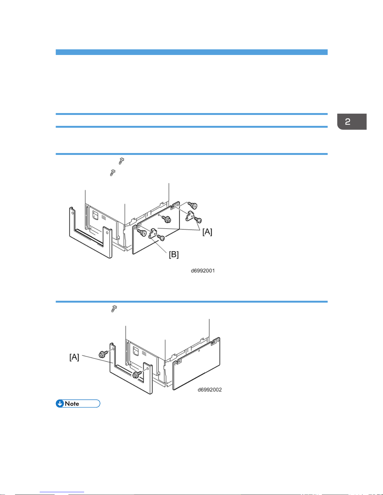
Covers
Rear Cover
1. Hold brackets [A] ( x 1 each)
2. Rear cover [B] ( x 3)
Right Cover
1. Right cover [A] ( x 2)
• Do not remove the anti-tip components [A] at the bottom of the unit.
5
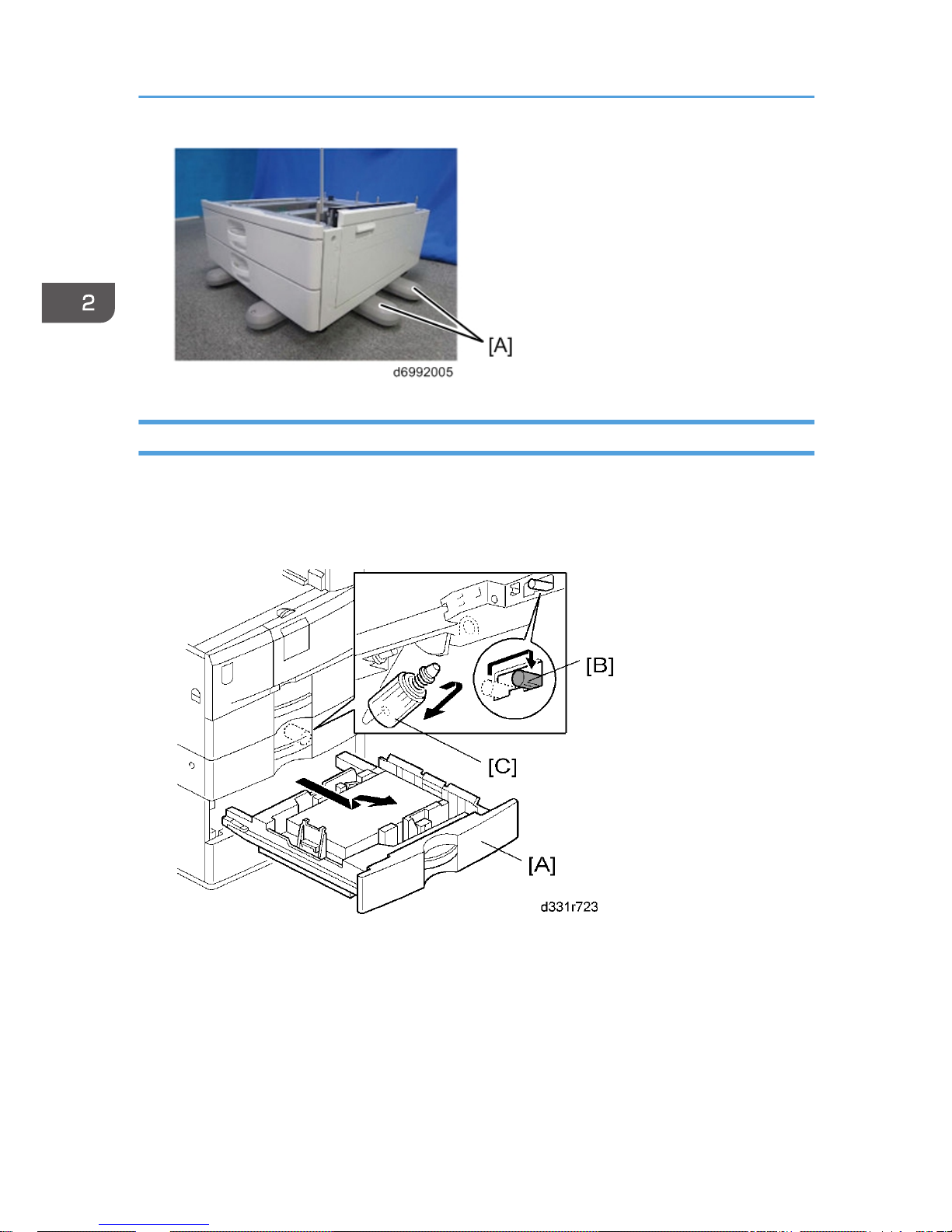
Feed Roller
1. Pull out the tray [A].
2.
Release the lock lever [B].
3. Feed roller [C]
2. Replacement and Adjustment
6
Drive Components
• Turn off the main power switch and unplug the machine before beginning any of the procedures in
this section.
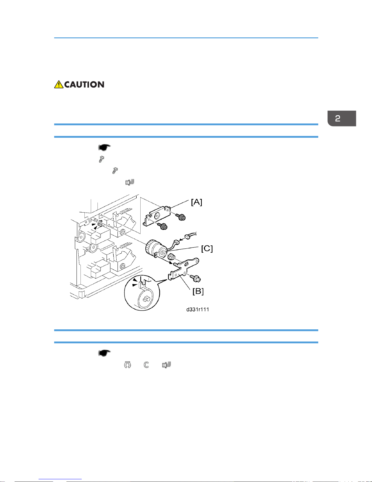
Upper Feed Clutch
1. Rear cover ( p.5 "Covers")
2.
Bracket [A] (
x 2)
3.
Hold bracket [B] (
x 1, bushing x 1)
4.
Upper feed clutch [C] (
x 1)
Lower Feed Clutch
1. Rear cover ( p.5 "Covers")
2.
Lower feed clutch [A] (
x 1, x 1, x 1)
Drive Components
7
 Loading...