

Page 1
User Guide
Getting Started
Selected Version
Print
Web Image Monitor
Adding Paper and Toner
Troubleshooting
Information for This Machine
For information not found in this manual,
see the online manuals available on our
web site (https://www.ricoh.com/).
For safe and correct use, be sure to read Safety Information before
using the machine.
Page 2

Page 3

TABLE OF CONTENTS
How to Read This Manuals................................................................................................................................4
Symbols Used in This Manuals......................................................................................................................4
1. Getting Started
Model-Specific Information............................................................................................................................... 5
Guide to Names and Functions of Components..............................................................................................6
Guide to Components....................................................................................................................................6
Connecting and Setting the Network............................................................................................................. 11
Setting Wired LAN.......................................................................................................................................11
Setting Wireless LAN...................................................................................................................................13
Connecting the USB Interface......................................................................................................................... 22
Connecting to the USB (Type B) Interface................................................................................................. 22
Connecting a Device to the Machine's USB Host Interface..................................................................... 22
Guide to Functions of the Machine's External Options.................................................................................24
Order of Option Installation............................................................................................................................25
Attaching the Paper Feed Unit........................................................................................................................ 26
The number of tray that you can install...................................................................................................... 27
Installing the Hard Disk....................................................................................................................................29
Installing the Wireless LAN interface board.................................................................................................. 34
Installing the IEEE 1284 interface board....................................................................................................... 35
Connecting to the IEEE 1284 Interface..................................................................................................... 36
Installing the USB device server......................................................................................................................37
Procedure for installing the USB device server..........................................................................................37
Connecting to the Extra Ethernet Interface with the USB Device Server Option.................................... 38
Specifying an IP address for the USB Device Server................................................................................40
Installing SD Card Options..............................................................................................................................43
Guide to the Names and Functions of the Control Panel..............................................................................45
Guide to the Names and Functions of the Control Panel Screen.................................................................47
Turning On/Off the Power..............................................................................................................................48
Turning On/Off the Main Power................................................................................................................48
Logging In the Machine...................................................................................................................................50
User Code Authentication Using a Printer Driver...................................................................................... 50
Logging In/Out Using the Control Panel...................................................................................................50
1
Page 4

2. Print
Installing the Printer Driver for Network Connection (Windows).................................................................53
Installing the PCL 6 Printer Driver from the CD-ROM............................................................................... 53
Installing the Printer Driver for USB Connection (Windows)........................................................................ 57
Installing the Printer Driver from the CD-ROM.......................................................................................... 57
Displaying the Printer Driver Properties.......................................................................................................... 60
Standard Printing..............................................................................................................................................61
When Using the PCL 6 Printer Driver..........................................................................................................61
Printing on Both Sides of Sheets......................................................................................................................65
How to Print on Both Sides of the Paper (When Using the PCL 6 Printer Driver)....................................65
Combining Multiple Pages into Single Page..................................................................................................66
How to Print Multiple Pages onto a Single Sheet (When Using the PCL 6 Printer Driver)..................... 66
Printing on Envelopes.......................................................................................................................................68
Configuring Envelope Settings Using the Control Panel...........................................................................68
Printing on Envelopes Using the Printer Driver...........................................................................................68
3. Web Image Monitor
Displaying Top Page........................................................................................................................................71
4. Adding Paper and Toner
Loading Paper.................................................................................................................................................. 73
Loading Paper into Paper Trays..................................................................................................................73
Loading Paper into the Bypass Tray...........................................................................................................76
Loading Orientation-fixed Paper or Two-sided Paper..............................................................................79
Recommended Paper.......................................................................................................................................81
When Loading Thick Paper.........................................................................................................................87
When Loading Envelopes........................................................................................................................... 88
Adding Toner....................................................................................................................................................90
Disposing of Used Print Cartridge.............................................................................................................. 92
5. Troubleshooting
When a Status Icon Is Displayed on the Control Panel................................................................................ 93
When a Panel Tone Beeps.............................................................................................................................. 94
Status Messages...............................................................................................................................................95
Alert Messages (Displayed on the Control Panel)........................................................................................ 97
Alert Messages (Printed on Error Logs and Reports).................................................................................. 103
2
Page 5
Cautions in Removing Jammed Paper..........................................................................................................108
Removing Jammed Paper..............................................................................................................................112
Paper Misfeed Message (A1)..................................................................................................................112
Paper Misfeed Message (A2)..................................................................................................................114
Paper Misfeed Message (B).....................................................................................................................117
Paper Misfeed Message (C).................................................................................................................... 120
Paper Misfeed Message (Y1) to (Y3)......................................................................................................123
Paper Misfeed Message (Z1).................................................................................................................. 125
6. Information for This Machine
ENERGY STAR Program................................................................................................................................129
Energy Saving Functions............................................................................................................................... 130
User Information on Electrical and Electronic Equipment (mainly Europe).......................... 132
Users in the countries where this symbol shown in this section has been specified in national law on
collection and treatment of E-waste.........................................................................................................132
All Other Users.......................................................................................................................................... 132
For Users in India.......................................................................................................................................132
For Turkey Only.........................................................................................................................................133
Note for the Battery and/or Accumulator Symbol (For EU countries only) (mainly Europe).....
.........................................................................................................................................................................134
Environmental Advice for Users (mainly Europe)....................................................................135
Users in the EU, Switzerland and Norway............................................................................................. 135
Notes to users in the state of California (Notes to Users in USA) (mainly North America). 136
Specifications for the Main Unit................................................................................................................... 137
Specifications for Printer................................................................................................................................141
Specifications for Lower Paper Tray (250 sheets)...................................................................................... 143
Specifications for Lower Paper Tray (500 sheets)...................................................................................... 144
Specifications for IEEE 1284 Interface Board.............................................................................................145
Specifications for Wireless LAN Interface Board........................................................................................146
Specifications for USB Device Server.......................................................................................................... 148
Copyright Information about Installed Applications...................................................................................149
INDEX...........................................................................................................................................................151
3
Page 6
How to Read This Manuals
Symbols Used in This Manuals
This manual uses the following symbols:
Indicates points to pay attention to when using functions. This symbol indicates points that may result in
the product or service becoming unusable or result in the loss of data if the instructions are not obeyed.
Be sure to read these explanations.
Indicates supplementary explanations of the machine's functions, and instructions on resolving user
errors.
Indicates where you can find further relevant information.
[ ]
Indicates the names of keys or buttons on the product or display.
(mainly Europe and Asia), (mainly Europe), or (mainly Asia)
(mainly North America)
Differences in the functions of Region A and Region B models are indicated by two symbols. Read the
information indicated by the symbol that corresponds to the region of the model you are using. For
details about which symbol corresponds to the model you are using, see page 5 "Model-Specific
Information" .
4
Page 7
1. Getting Started
DYR224
This chapter describes how to start using this machine.
Model-Specific Information
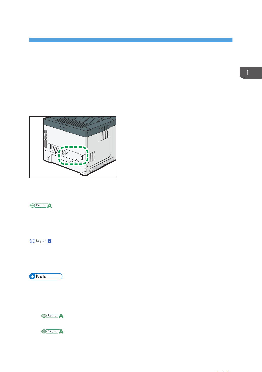
This section explains how you can identify the region your machine belongs to.
There is a label on the rear of the machine, located in the position shown below. The label contains
details that identify the region your machine belongs to. Read the label.
The following information is region-specific. Read the information under the symbol that corresponds to
the region of your machine.
(mainly Europe and Asia)
If the label contains the following, your machine is a region A model:
• CODE XXXX -27, -29
• 220–240 V
(mainly North America)
If the label contains the following, your machine is a region B model:
• CODE XXXX -17
• 120–127 V
• Dimensions in this manual are given in two units of measure: metric and inch. If your machine is a
Region A model, refer to the metric units. If your machine is a Region B model, refer to the inch
units.
• If your machine is a region A model and "CODE XXXX -27" is printed on the label, see
" (mainly Europe)" also.
• If your machine is a region A model and "CODE XXXX -29" is printed on the label, see
" (mainly Asia)" also.
5
Page 8
13
11
12
10
8
7
9
6
4
4
5
123
DYR151
1. Getting Started
Guide to Names and Functions of Components
Guide to Components
• Do not obstruct the machine's vents. Doing so risks fire caused by overheated internal
components.
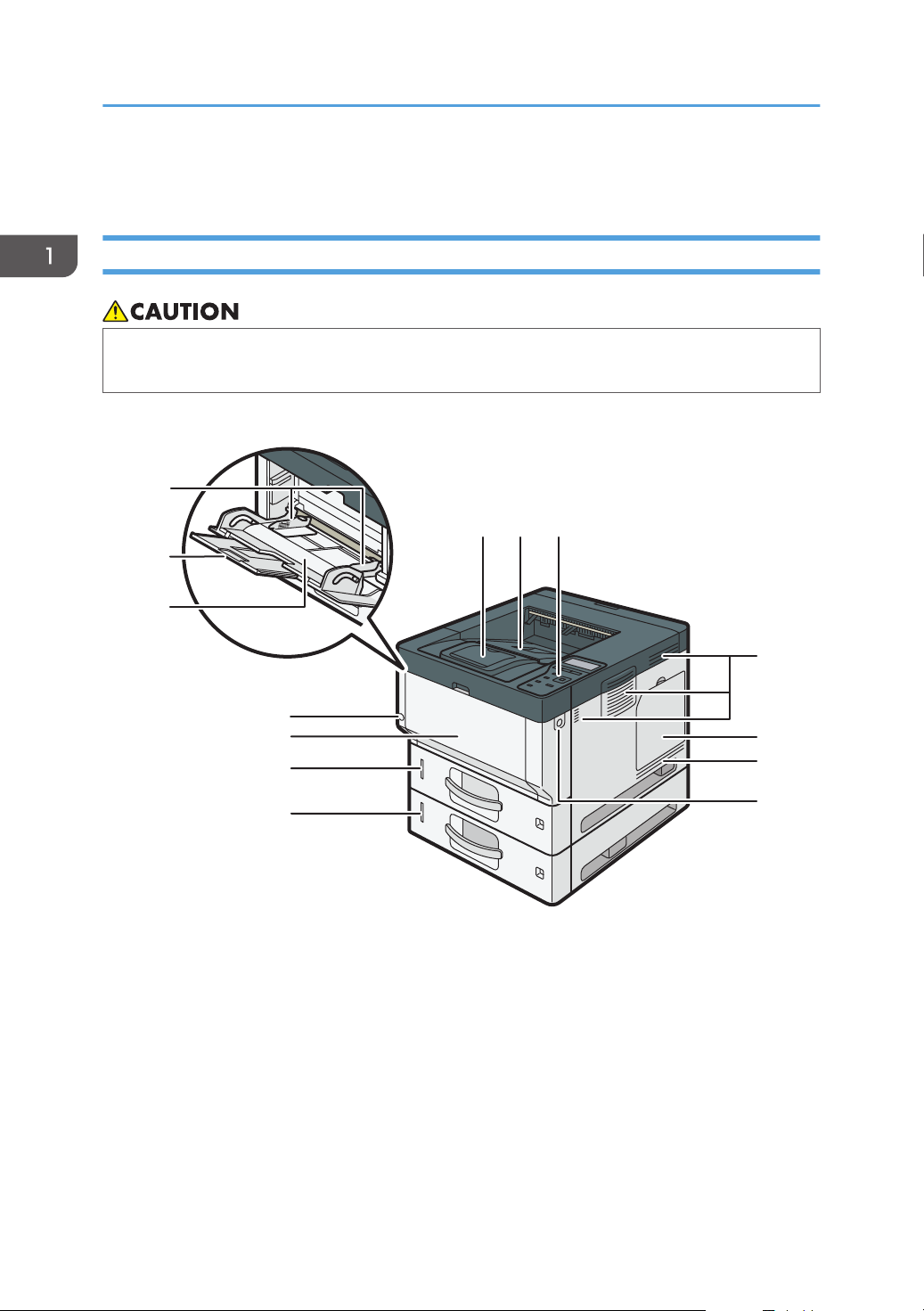
Front and right view
1. Stop fence
Open this fence to prevent paper from falling off.
2. Standard tray
Output is stacked here with the print side down.
3. Control panel
See page 45 "Guide to the Names and Functions of the Control Panel".
4. Ventilation holes
Prevent overheating.
6
Page 9

Guide to Names and Functions of Components
5. Memory cover
Open to install a hard disk.
6. Front cover open button
Push this button to open the front cover.
7. Lower paper trays
Load paper here.
For details, see page 24 "Guide to Functions of the Machine's External Options".
8. Tray 1
Load paper here.
9. Front cover
Open to access the inside of the machine and remove jammed paper.
Open here to replace the print cartridge and the drum unit.
10. Main power switch
To operate the machine, the main power switch must be on. If it is off, turn the switch on.
See page 48 "Turning On/Off the Power".
11. Bypass tray
Use to print on thick paper, OHP transparencies, envelopes, and label paper (adhesive labels).
12. Extender for the bypass tray
Pull this extender out when loading A4 , 81/2 × 11 or larger size paper in the bypass tray.
13. Paper guides
When loading paper in the bypass tray, align the paper guides flush against the paper.
7
Page 10
DYR156
5
6
7
8
9
324 1 1
1. Getting Started
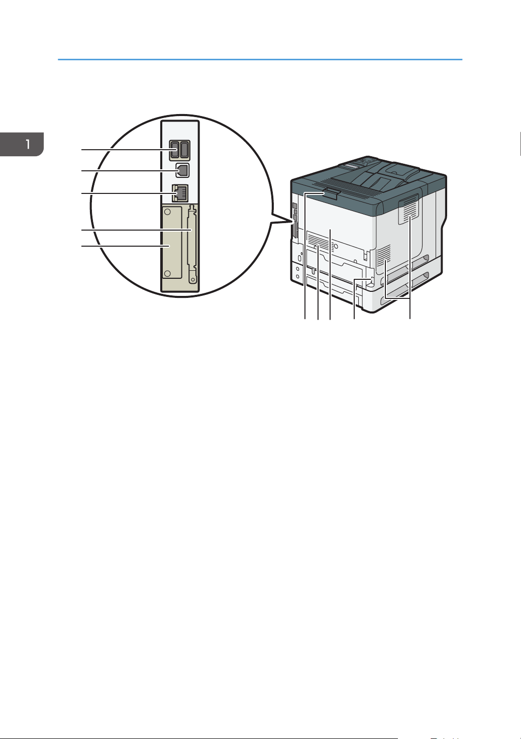
Rear and left view
1. Vents
Prevent overheating.
2. Power connector
Connect the power cord to the machine. Insert the other end into an electrical outlet.
3. Rear cover
Open to access the inside of the machine and remove jammed paper.
Open here to replace the fusing unit.
4. Rear cover open lever
Pull this lever to open the rear cover.
5. Slot
Optional interface boards can be inserted.
6. Expansion card slots
Remove the cover to install SD cards.
7. Ethernet port
Use a network interface cable to connect the machine to a network.
8. USB 2.0 [Type B] port
Use a USB cable to connect the machine to a computer.
9. USB Host Interface
Connect external devices such as a card authentication device.
8
Page 11
Interior: Front view
DYR153
1
2
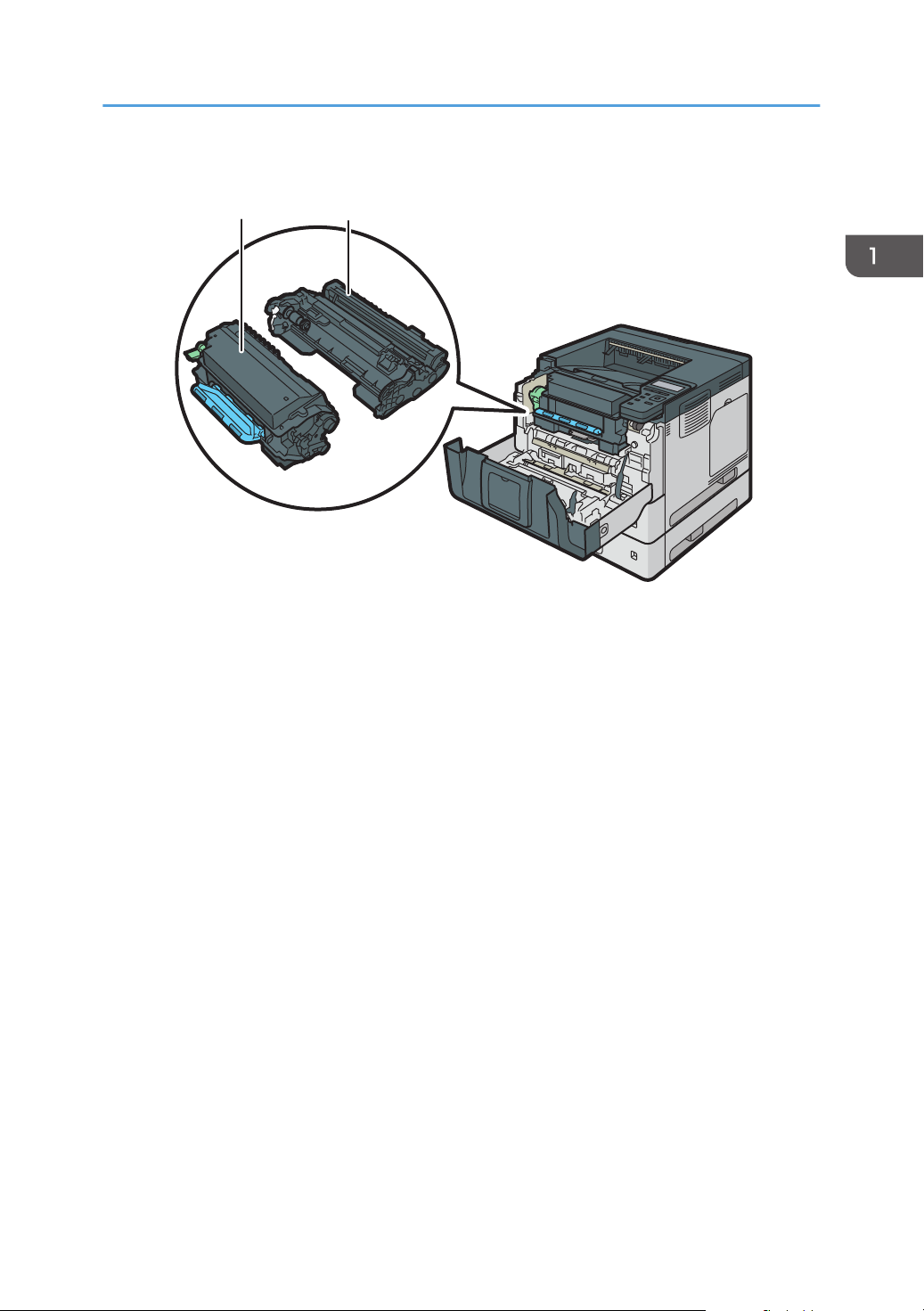
Guide to Names and Functions of Components
1. Print cartridge
To remove jammed paper, pull out the Print cartridge and drum unit as a single unit.
Messages appear on the screen when the print cartridge needs to be replaced, or a new cartridge needs to
be prepared.
For details about the messages that appear on the screen when consumables need to be replaced, see
"Adding Toner", Maintenance.
When you remove jammed paper, pull out the print cartridge with the drum unit. If you want to remove only
the print cartridge, pull down the lever on the left side of the print cartridge, and then pull the print cartridge
out.
2. Drum unit
Messages appear on the screen when the drum unit needs to be replaced, or a new drum unit needs to be
prepared.
For details about the messages that appear on the screen when consumables need to be replaced, see
"Replacing the Drum Unit", Maintenance.
For P502:
When the drum unit needs to be replaced, contact your service representative.
9
Page 12
DYR154
1
1. Getting Started
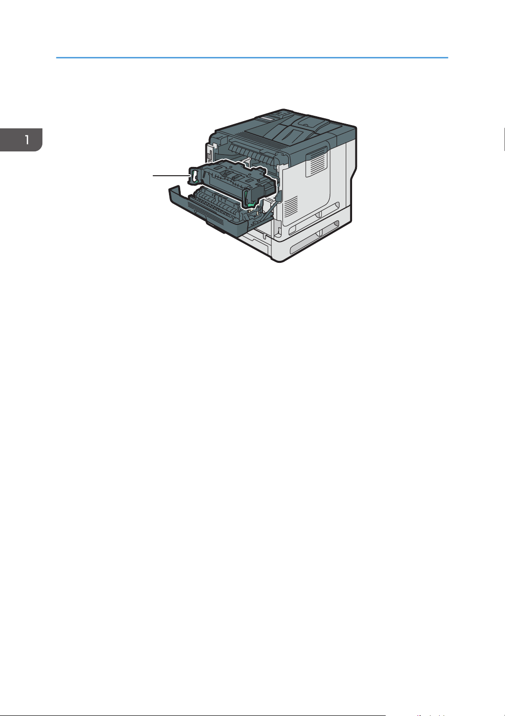
Interior: Rear view
1. Fusing unit
Pull out the fusing unit and remove jammed paper.
Messages appear on the screen when the fusing unit needs to be replaced, or a new fusing unit needs to be
prepared.
For details about the messages that appear on the screen when consumables need to be replaced, see
"Replacing the Maintenance Kit", Maintenance.
For P502:
When the fusing unit needs to be replaced, contact your service representative.
10
Page 13
DYR209
Connecting and Setting the Network
Connecting and Setting the Network
Setting Wired LAN
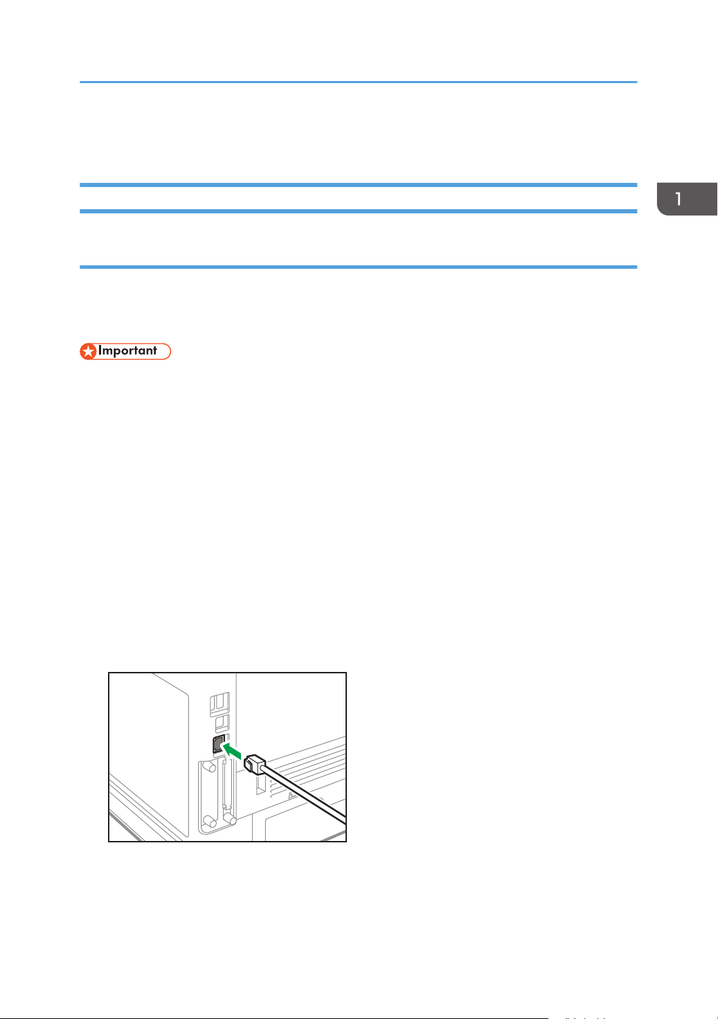
Connecting Ethernet Interface
This section describes how to connect an Ethernet interface cable to the Ethernet port.
If you use an Ethernet interface cable that supports 1000BASE-T, set [Ethernet Speed] to [Auto Select:
Enable 1Gbps] in [Network] in [Host Interface].
• Use the following Ethernet cables.
• When using 100BASE-TX/10BASE-T:
Unshielded Twisted Pair Cable (UTP) or Shielded Twisted Pair Cable (STP) and Category type
5 or more
• When using 1000BASE-T:
Unshielded Twisted Pair Cable (UTP) or Shielded Twisted Pair Cable (STP) and Category type
5e or more
• When you use IPv6, set [IPv6] to [Active] in [Effective Protocol] in [Network] of [Host Interface].
IPv6 is inactive as a factory default. When you enable IPv6, a link-local address is automatically
set.
• When you use IPv6, consult your network administrator.
1. Make sure the main power is switched off.
2. Connect the Ethernet interface cable to the Ethernet port.
3. Connect the other end of the Ethernet interface cable to a network connection device such
as a hub.
11
Page 14
3
2
1
DRS703
1. Getting Started
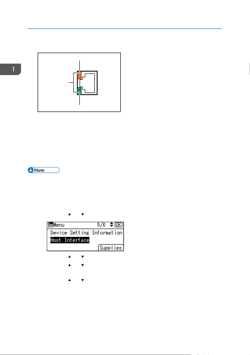
4. Turn on the main power switch of the machine.
1. Indicator (orange)
When 100BASE-TX is operating, the LED is lit orange.
2. Indicator (green)
When 10BASE-T is operating, the LED is lit green.
3. Indicators (both orange and green)
When 1000BASE-T is operating, both LEDs are lit.
• When Energy Saver mode is enabled, the LEDs may not light up.
Obtaining an IP address automatically (IPv4 DHCP)
The machine is set to obtain IP addresses automatically as a factory default.
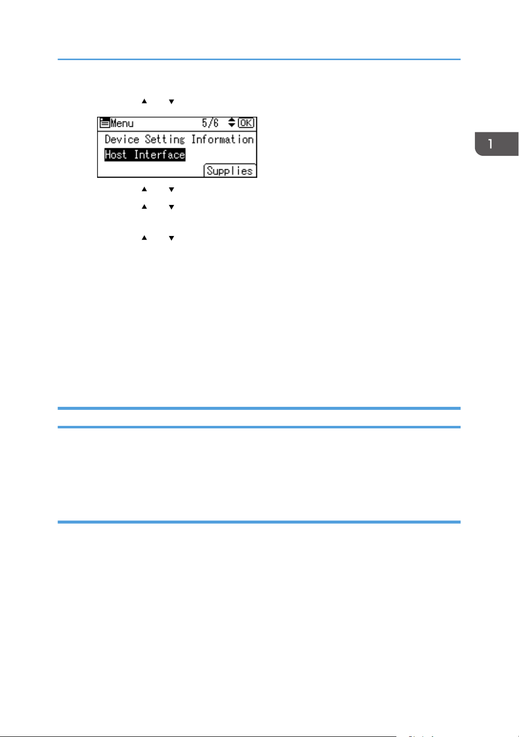
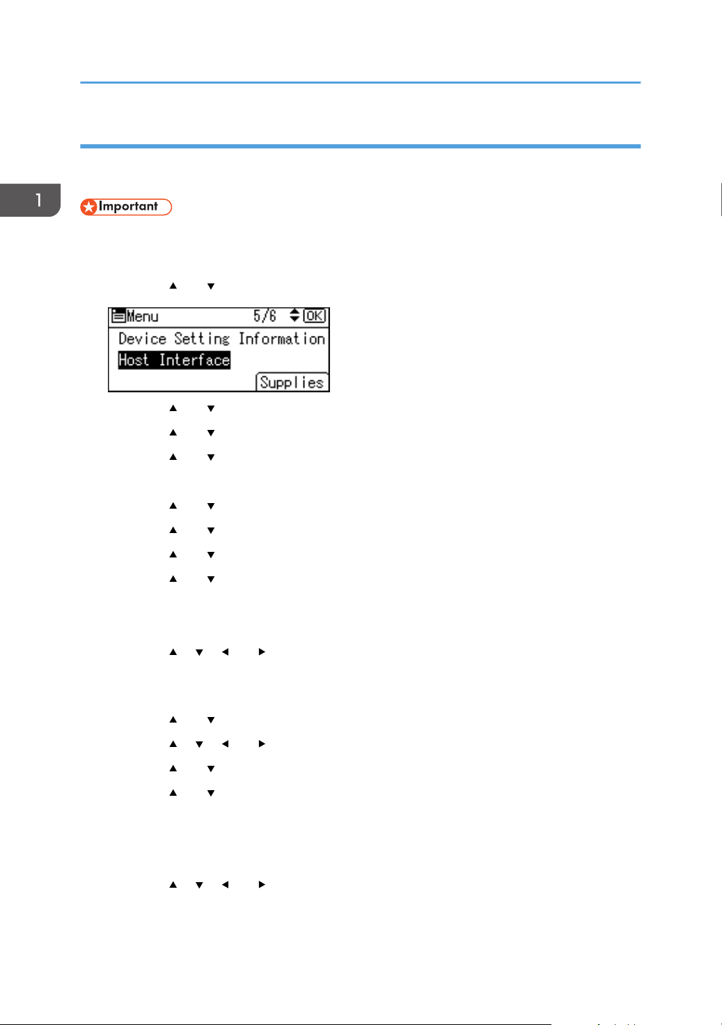
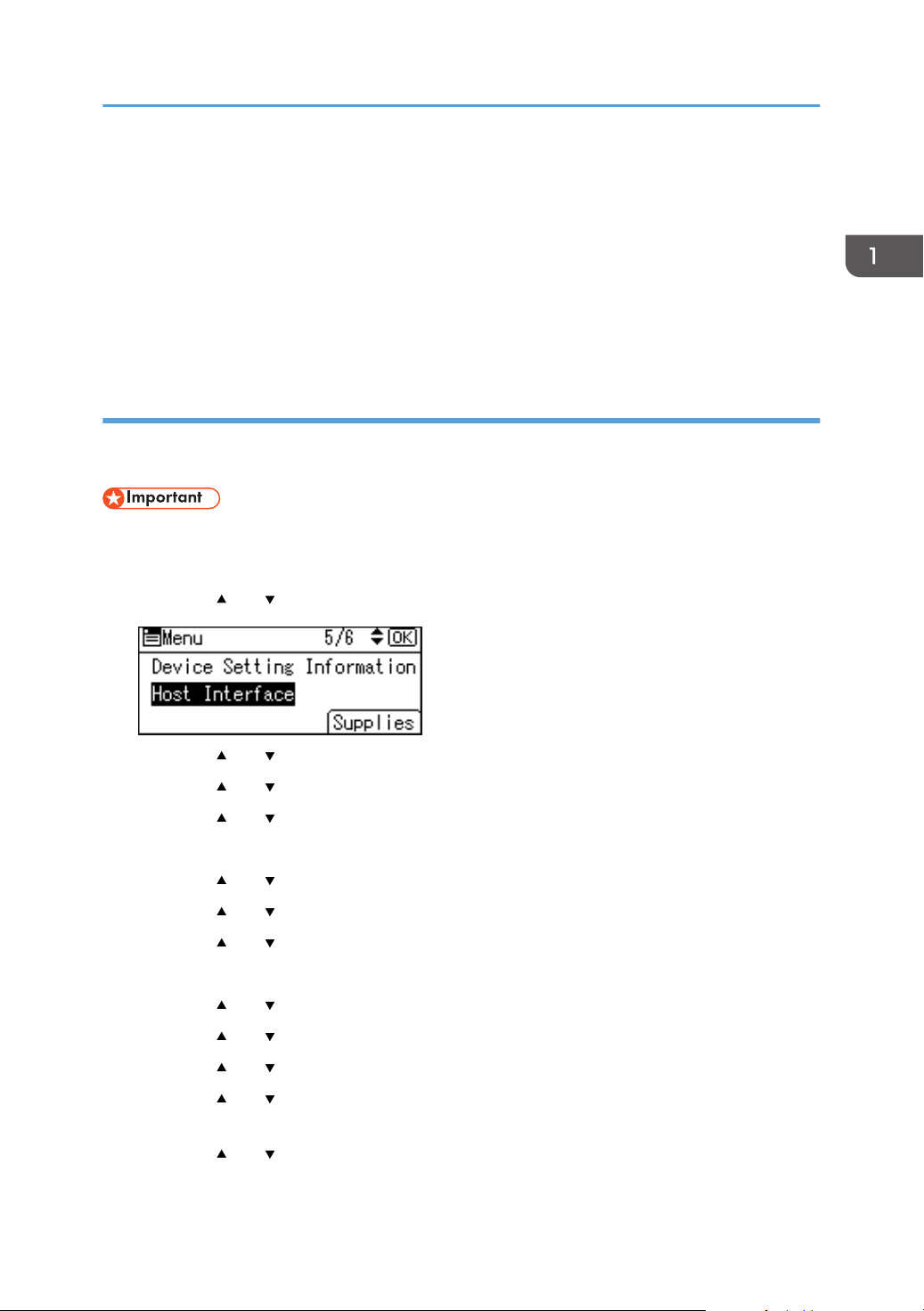
1. Press the [Menu] key.
2. Press the [ ] or [ ] key to select [Host Interface], and then press the [OK] key.
3. Press the [ ] or [ ] key to select [Network], and then press the [OK] key.
4. Press the [ ] or [ ] key to select [Machine IPv4 Address], and then press the [OK]
key.
5. Press the [ ] or [ ] key to select [Auto-Obtain (DHCP)], and then press the [OK] key.
Specifying an IP address (IPv4)
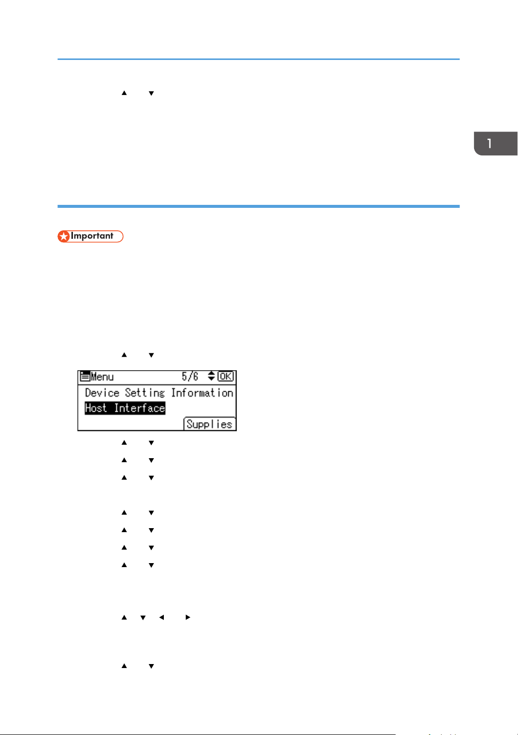
1. Press the [Menu] key.
12
Page 15
Connecting and Setting the Network
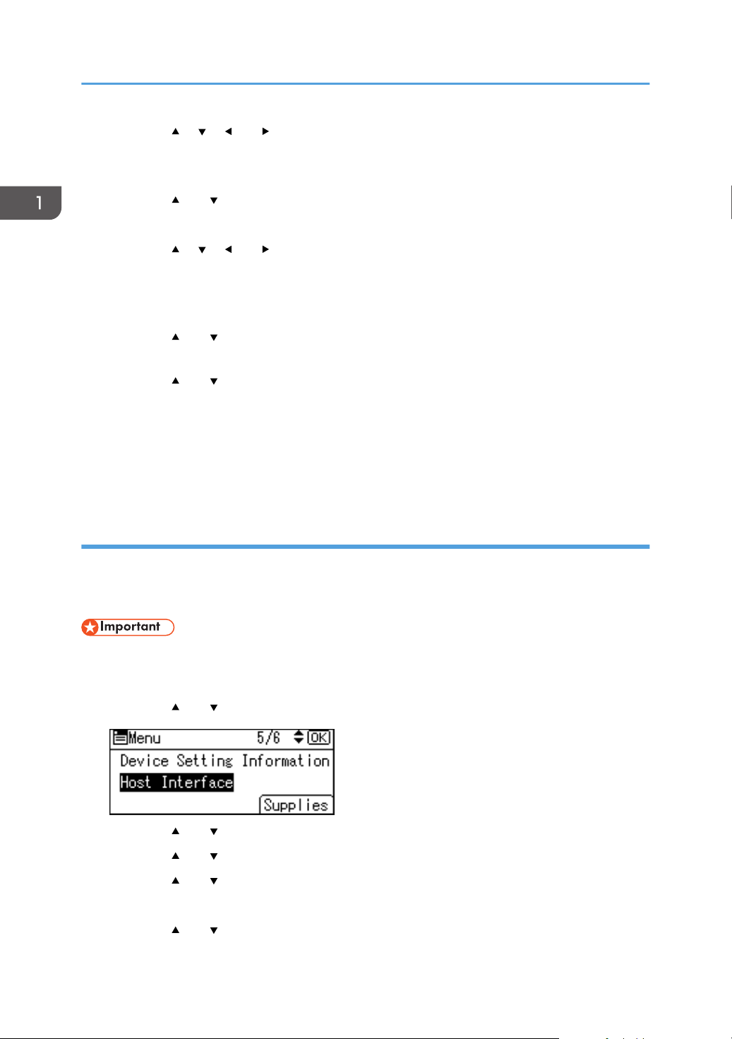
2. Press the [ ] or [ ] key to select [Host Interface], and then press the [OK] key.
3. Press the [
4. Press the [ ] or [ ] key to select [Machine IPv4 Address], and then press the [OK]
key.
5. Press the [ ] or [ ] key to select [Specify], and then press the [OK] key.
6. Press the selection key beneath [IP Add.], and then enter the IP address.
7. Press the [OK] key.
8. Press the selection key beneath [Subnet M], and then enter the subnet mask.
9. Press the [OK] key.
10. Press the selection key beneath [Gateway], and then enter the gateway.
11. Press the [OK] key.
12. Confirm the [Specify] is selected, and then press the [OK] key.
13. Press the [Escape] key.
] or [ ] key to select [Network], and then press the [OK] key.
Setting Wireless LAN
Wireless LAN connection is available when you install the optional Wireless LAN interface board.
See page 34 "Installing the Wireless LAN interface board" for how to install the Wireless LAN
interface board.
Selecting the communication mode for the Wireless LAN
Select the communication mode according to your environment.
13
Page 16
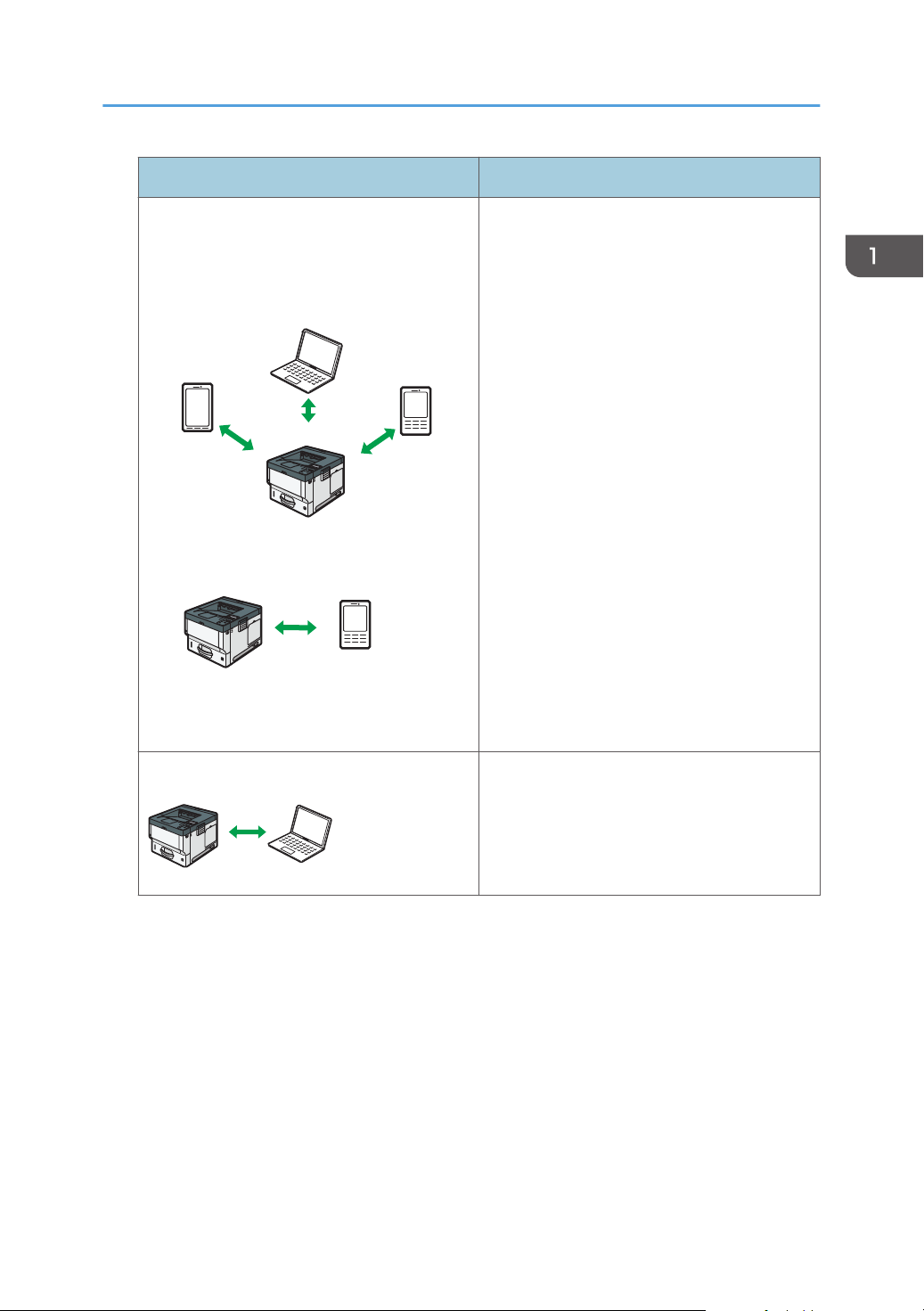
DVL258
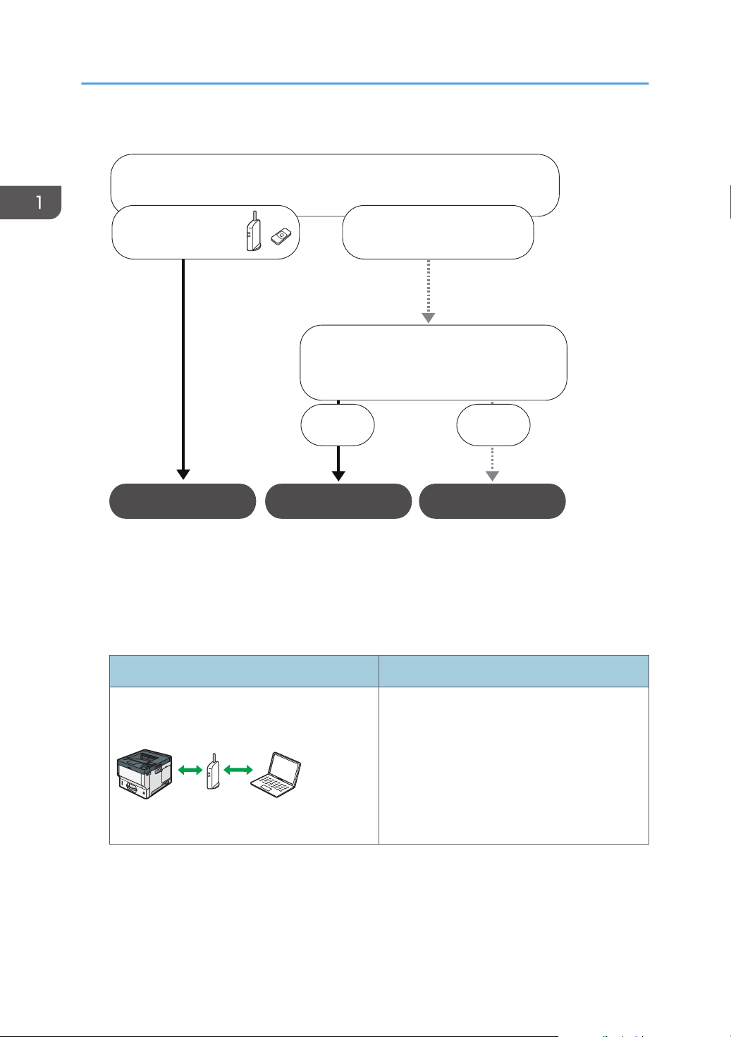
Which wireless LAN environment are you using?
Infrastructure
Wireless Direct Mode
Wireless Direct
Group Owner Mode
A wireless LAN
router is being used.
A wireless LAN router
is not being used.
Do you know how to specify the SSID*
or the password for connecting your
device to a network?
1
Yes No
DYR230
1. Getting Started
How to select the mode
*1
You can also connect via Ad hoc mode. For detailed information, see the explanation for each
mode.
About the modes
Infrastructure Mode
SSID is an identifier to distinguish Wireless LAN networks. It is also called a "Network name" or "Access
point name".
Mode Description
In infrastructure mode, you can connect
several devices and the machine via a wireless
LAN router.
You can also print data on a network, such as
a website, even when a device is connected.
The machine's communication mode is set to
infrastructure mode as a factory default.
14
Page 17
Mode Description
DYR231
DVK543
DYR232
Wireless Direct Mode
• Wireless Direct Group Owner Mode
• Wireless Direct
Connecting and Setting the Network
In Wireless Direct Mode, you can connect the
machine and a device without using a wireless
LAN router.
There are two types of connection methods in
Wireless Direct mode.
• Wireless Direct Group Owner Mode
You can connect several devices, including
devices that are not compliant with Wi-Fi
Direct. You need to enter the SSID and
password of the machine on the device you
want to connect.
• Wireless Direct
You can connect the machine and a device
directly to each other.
Select the machine from the device you want to
connect.
Only devices that are Android 4.0 or later and
support Wi-Fi Direct can be connected.
You cannot print data on a network, such as a
website, when a device is connected.
Ad-hoc Mode
You need to set the ad-hoc channel and other
settings, on the device you are connecting.
You cannot select WPA2 as the security
method. You cannot print data on a network,
such as a website, when a device is connected.
Procedure for the settings
For Ad hoc Mode, see page 16 "Connecting in Ad hoc Mode".
For Infrastructure Mode, see page 17 "Connecting in Infrastructure Mode".
For Direct Connection Mode, see page 19 "Connecting in Direct Connection Mode".
For Direct Connection Group Owner Mode, see page 20 "Connecting in Direct Connection
Group Owner Mode".
15
Page 18
1. Getting Started
Connecting in Ad hoc Mode
In Ad hoc mode, you can specify an SSID to the machine, and connect your computer directly to the
machine via a wireless LAN.
• The Wireless LAN interface board must be installed to use Ad hoc mode.
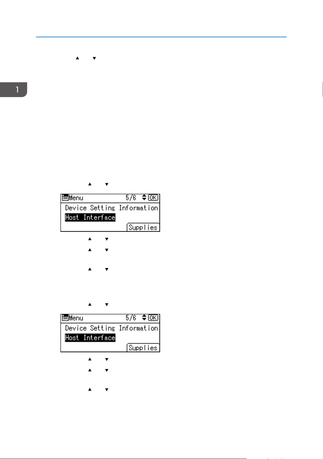
1. Press the [Menu] key.
2. Press the [
] or [ ] key to select [Host Interface], and then press the [OK] key.
3. Press the [ ] or [ ] key to select [Network], and then press the [OK] key.
4. Press the [ ] or [ ] key to select [LAN Type], and then press the [OK] key.
5. Press the [ ] or [ ] key to select [Wireless LAN], and then press the [OK] key.
6. Press the [Escape] key.
7. Press the [
] or [ ] key to select [Wireless LAN], and then press the [OK] key.
8. Press the [ ] or [ ] key to select [Communication Mode], and then press the [OK] key.
9. Press the [ ] or [ ] key to select [802.11 Ad-hoc Mode], and then press the [OK] key.
10. Press the [ ] or [ ] key to select [SSID Setting], and then press the [OK] key.
11. Press the selection key beneath [Enter SSID].
12. Press the selection key beneath [Enter].
13. Press the [ ], [ ], [ ] or [ ] key to select a character, and then press the [OK] key to
enter the SSID.
14. Press the selection key beneath [Accept] when you finish entering the SSID.
15. Press the [ ] or [ ] key to select [Ad-hoc Channel], and then press the [OK] key.
16. Press the [ ], [ ], [ ] or [ ] key to select a channel, and then press the [OK] key.
17. Press the [ ] or [ ] key to select [Security Method], and then press the [OK] key.
18. Press the [ ] or [ ] key to select [WEP], and then press the selection key beneath
[Details].
To not use security setting, select [No].
19. Press the selection key beneath [Enter].
20. Press the [ ], [ ], [ ] or [ ] key to select a character, and then press the [OK] key to
enter the WEP key.
21. Press the selection key beneath [Accept].
16
Page 19
Connecting and Setting the Network
22. Press the [ ] or [ ] key to select [WEP], and then press the [OK] key.
The settings are complete.
You can connect the device in Ad hoc mode by specifying the SSID, channel, and security method that
are specified for the machine.
See the instructions supplied with the device for how to connect it in ad hoc mode.
Connecting in Infrastructure Mode
Use infrastructure mode to connect the machine to an access point.
• The Wireless LAN interface board must be installed to use Infrastructure mode.
• When you use IPv6, set [IPv6] to [Active] in [Effective Protocol] in [Network] of [Host Interface].
IPv6 is inactive as a factory default. When you enable IPv6, a link-local address is automatically
set.
• When you use IPv6, consult your network administrator.
1. Press the [Menu] key.
2. Press the [ ] or [ ] key to select [Host Interface], and then press the [OK] key.
3. Press the [ ] or [ ] key to select [Network], and then press the [OK] key.
4. Press the [ ] or [ ] key to select [LAN Type], and then press the [OK] key.
5. Press the [ ] or [ ] key to select [Wireless LAN], and then press the [OK] key.
6. Press the [Escape] key.
7. Press the [ ] or [ ] key to select [Wireless LAN], and then press the [OK] key.
8. Press the [ ] or [ ] key to select [Communication Mode], and then press the [OK] key.
9. Press the [ ] or [ ] key to select [Infrastructure Mode], and then press the [OK]
10. Press the [ ] or [ ] key to select [SSID Setting], and then press the [OK]
11. Press the selection key beneath [SSID].
12. Press the selection key beneath [Enter].
13. Press the [ ], [ ], [ ] or [ ] key to select a character, and then press the [OK] key to
enter the SSID that you want to connect to.
14. Press the selection key beneath [Accept] when you finish entering the SSID.
15. Press the [ ] or [ ] key to select [Security Method], and then press the [OK] key.
17
Page 20
1. Getting Started
16. Press the [ ] or [ ] key to select the security method that is specified for the access point
you want to connect to.
17. Press the selection key beneath [Enter].
Select [WEP] or [WPA2], and then press the selection key beneath [Details] to enter your
password.
If you do not use security setting, select [No].
The settings are complete.
To check the connection status, enter [Wireless LAN Signal] in [Wireless LAN] and confirm the signal
status.
Obtaining an IP address automatically (IPv4 DHCP)
The machine is set to obtain IP addresses automatically as a factory default.
1. Press the [Menu] key.
2. Press the [ ] or [ ] key to select [Host Interface], and then press the [OK] key.
3. Press the [ ] or [ ] key to select [Network], and then press the [OK] key.
4. Press the [ ] or [ ] key to select [Machine IPv4 Address], and then press the [OK]
key.
5. Press the [ ] or [ ] key to select [Auto-Obtain (DHCP)], and then press the [OK] key.
Specifying an IP address (IPv4)
1. Press the [Menu] key.
2. Press the [ ] or [ ] key to select [Host Interface], and then press the [OK] key.
3. Press the [ ] or [ ] key to select [Network], and then press the [OK] key.
4. Press the [ ] or [ ] key to select [Machine IPv4 Address], and then press the [OK]
key.
5. Press the [ ] or [ ] key to select [Specify], and then press the [OK] key.
6. Press the selection key beneath [IP Add.], and then enter the IP address.
7. Press the [OK] key.
18
Page 21
Connecting and Setting the Network
8. Press the selection key beneath [Subnet M], and then enter the subnet mask.
9. Press the [OK] key.
10. Press the selection key beneath [Gateway], and then enter the gateway.
11. Press the [OK] key.
12. Confirm the [Specify] is selected, and then press the [OK] key.
13. Press the [Escape] key.
Connecting in Direct Connection Mode
To connect another device and the machine directly using the wireless direct function, use the Wireless
Direct mode.
• The Wireless LAN interface board must be installed to use Wireless Direct mode.
1. Press the [Menu] key.
2. Press the [ ] or [ ] key to select [Host Interface], and then press the [OK] key.
3. Press the [ ] or [ ] key to select [Direct Connection], and then press the [OK] key.
4. Press the [ ] or [ ] key to select [Active/Inactive], and then press the [OK] key.
5. Press the [ ] or [ ] key to select [Active], and then press the [OK] key.
6. Press the [Escape] key.
7. Press the [ ] or [ ] key to select [Network], and then press the [OK] key.
8. Press the [ ] or [ ] key to select [LAN Type], and then press the [OK] key.
9. Press the [ ] or [ ] key to select [Wireless LAN], and then press the [OK] key.
10. Press the [Escape] key.
11. Press the [ ] or [ ] key to select [Wireless LAN], and then press the [OK] key.
12. Press the [ ] or [ ] key to select [Communication Mode], and then press the [OK] key.
13. Press the [ ] or [ ] key to select [Direct Connection Mode], and then press the [OK] key.
14. Press the [ ] or [ ] key to select [Direct Connection Settings], and then press the [OK]
key.
15. Press the [ ] or [ ] key to select [Device Name], and then press the [OK] key.
16. Press the selection key beneath [Enter].
19
Page 22
1. Getting Started
17. Press the [ ], [ ], [ ] or [ ] key to select a character, and then press the [OK] key to
enter the device name.
18. Press the selection key beneath [Accept] when you finish entering the device name.
19. Press the [ ] or [ ] key to select [Connection Password], and then press the [OK] key.
20. Press the selection key beneath [Enter].
21. Press the [ ], [ ], [ ] or [ ] key to select a character, and then press the [OK] key to
enter the connection password.
22. Press the selection key beneath [Accept] when you finish entering the connection
password.
23. Press the [ ] or [ ] key to select [WLAN: EasySetup/Direct Con], and then press the [OK]
key.
24. Press the [ ] or [ ] key to select [Push Button Method], and then press the [OK] key.
25. Press the selection key beneath [Start].
The settings are complete.
Operate the push buttons on the device that you want to connect.
See the instructions supplied for the device for how to connect it in Wireless Direct mode.
Connecting in Direct Connection Group Owner Mode
To connect to multiple wireless direct-compliant devices by using the machine as a simple access point,
use the Direct Connection Group Owner mode. Up to nine devices can be connected. Non-wireless
direct-compliant devices can be connected too.
• The Wireless LAN interface board must be installed to use Wireless Direct Group Owner mode.
1. Press the [Menu] key.
2. Press the [ ] or [ ] key to select [Host Interface], and then press the [OK] key.
3. Press the [ ] or [ ] key to select [Direct Connection], and then press the [OK] key.
4. Press the [ ] or [ ] key to select [Active/Inactive], and then press the [OK] key.
5. Press the [ ] or [ ] key to select [Active], and then press the [OK] key.
20
6. Press the [Escape] key.
7. Press the [ ] or [ ] key to select [Network], and then press the [OK] key.
Page 23
Connecting and Setting the Network
8. Press the [ ] or [ ] key to select [LAN Type], and then press the [OK] key.
9. Press the [ ] or [ ] key to select [Wireless LAN], and then press the [OK] key.
10. Press the [Escape] key.
11. Press the [ ] or [ ] key to select [Wireless LAN], and then press the [OK] key.
12. Press the [ ] or [ ] key to select [Communication Mode], and then press the [OK] key.
13. Press the [ ] or [ ] key to select [Dir Con: Group Owner Mode], and then press the [OK]
key.
14. Press the [ ] or [ ] key to select [Direct Connection Settings], and then press the [OK]
key.
15. Press the [ ] or [ ] key to select [Device Name], and then press the [OK] key.
16. Press the selection key beneath [Enter].
17. Press the [ ], [ ], [ ] or [ ] key to select a character, and then press the [OK] key to
enter the device name.
18. Press the selection key beneath [Accept] when you finish entering the device name.
19. Press the [ ] or [ ] key to select [Connection Password], and then press the [OK] key.
20. Press the selection key beneath [Enter].
21. Press the [
], [ ], [ ] or [ ] key to select a character, and then press the [OK] key to
enter the connection password.
22. Press the selection key beneath [Accept] when you finish entering the connection
password.
23. Press the [ ] or [ ] key to select [WLAN:EasySetup/Direct Con], and then press the [OK]
key.
24. Press the [ ] or [ ] key to select [Push Button Method], and then press the [OK] key.
25. Press the selection key beneath [Start].
The settings are complete.
Operate the push buttons on the device that you want to connect.
See the instructions supplied for the device for how to connect it by Wireless Direct mode.
21
Page 24
DYR210
1. Getting Started
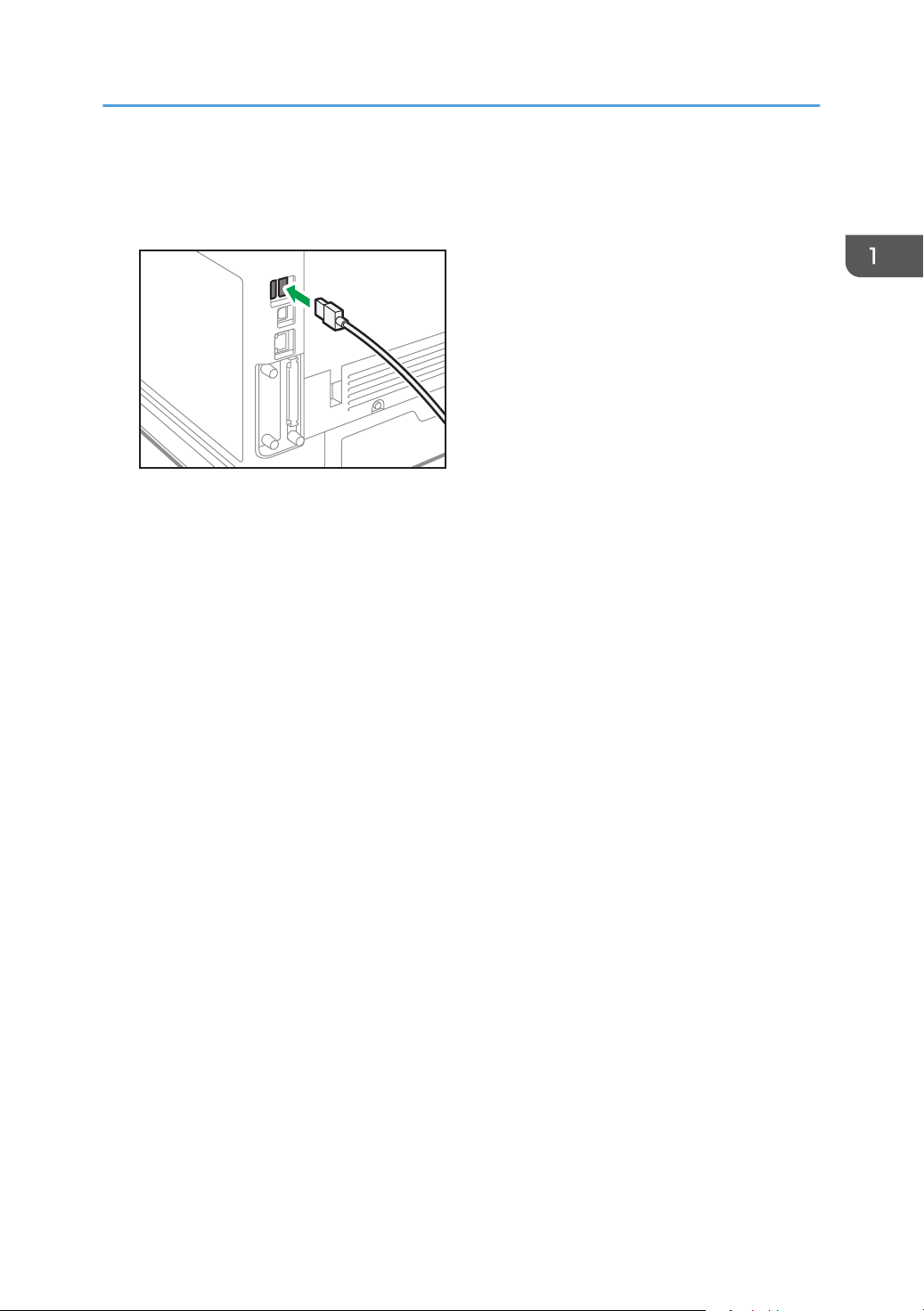
Connecting the USB Interface
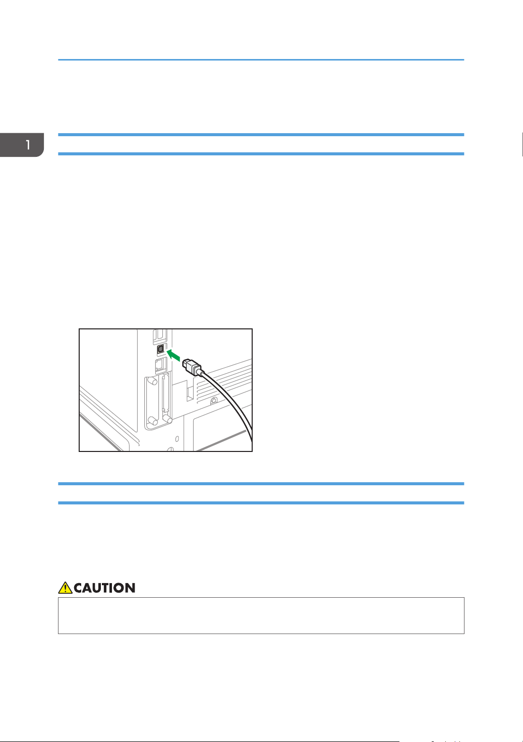
Connecting to the USB (Type B) Interface
This section describes how to connect a USB 2.0 (Type B) interface cable to the USB 2.0 port on the
machine.
This machine does not come with a USB interface cable. Make sure you purchase the appropriate cable
for the machine (connector shape) and your computer.
Use a five meter (197 inch) or shorter cable which supports USB2.0 (Type B) interface.
1. Connect a USB2.0 (Type B) interface cable to the USB2.0 port.
Connecting a Device to the Machine's USB Host Interface
This section explains how to connect a device to the machine's USB host interface.
This machine does not come with a USB interface cable. Make sure you purchase the appropriate cable
for the machine (connector shape) and the device.
Use a five meter (197 inch) or shorter cable which supports USB Host Interface.
• Connect any of the following devices to the USB 2.0 interface: Digital camera, USB keyboards,
and IC card readers. Connecting other devices may cause a malfunction.
22
Page 25
DYR211
Connecting the USB Interface
1. Connect one end of the USB interface device to the machine's USB host interface.
If you are using a USB interface cable, connect the other end of it to a device such as card
authentication one.
23
Page 26
1
2
DYR155
1. Getting Started
Guide to Functions of the Machine's External Options
1. Lower paper trays
You can attach up to three lower paper trays.
There are two types of trays, each holding up to 250 or 500 sheets of paper.
These trays can be used in any combination.
A customer engineer may be required to install this, depending on the number of levels being installed.
Contact your authorized service representative. For details, see "Attaching the Paper Feed Unit", Setup.
2. Caster Table
A table with casters to place this machine.
24
Page 27

Order of Option Installation
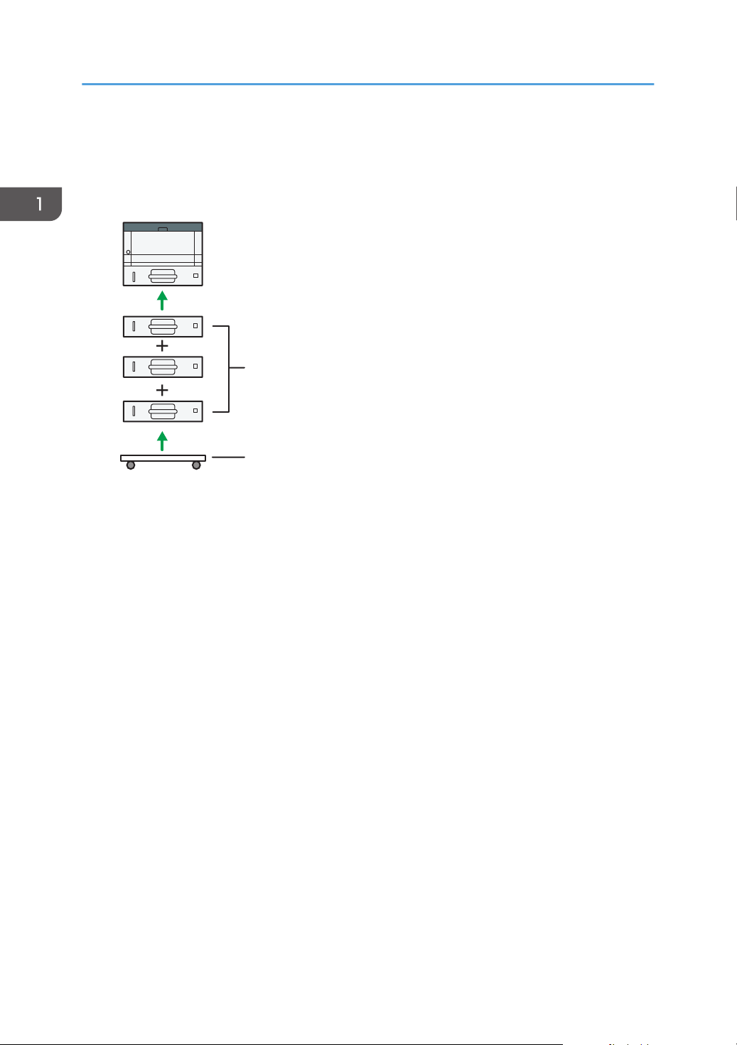
Order of Option Installation
When installing multiple options, the following order is recommended:
1. Attach the Lower paper tray (250 sheets) and the Lower paper tray (500 sheets).
You can attach up to three paper feed units by any combination.
2. Install the Hard disk.
Install the Hard disk to the install area of the controller board.
3. Install the interface board.
Install in the slot of the controller board.
Only one interface board can be installed.
4. Insert SD card.
Insert in the SD card slot of the controller board.
There are two slots for SD cards.
Each slot supports different types of SD cards.
If you want to use two or more SD cards that can be inserted in the same slot, contact your sales or
service representative.
25
Page 28
DYR201
1. Getting Started
Attaching the Paper Feed Unit
• It is dangerous to handle the power cord plug with wet hands. Doing so could result in electric
shock.
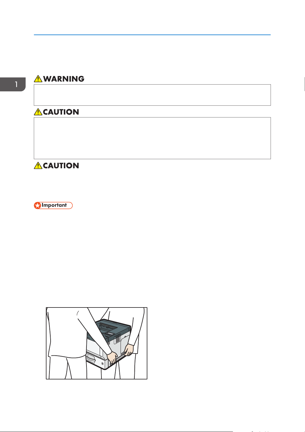
• The machine weighs approximately 19.3 kg (42.6 lb.) (Main unit only, including consumables.)
• When moving the machine, use the inset grips on both sides, and lift slowly. The machine will
break or cause injury if dropped.
• Lifting the paper feed unit carelessly or dropping may cause injury.
• Unplug the power cord from the wall outlet before you move the machine. While moving the
machine, take care that the power cord is not damaged under the machine. Failing to take these
precautions could result in fire or electric shock.
• Do not place the machine directly on the floor.
• When attaching multiple options, attach the paper feed unit first.
• To attach two paper feed units at the same time, first stack them one upon the other, and then
attach them as a single unit.
• Before turning on the power, remove the packaging material from the paper feed unit.
1. Check the contents of the package.
2. Turn the machine off and unplug the power cord.
3. Remove the packaging from the paper feed unit.
4. Lift the machine using the inset grips on both sides of the machine.
26
Page 29
DYR212
Attaching the Paper Feed Unit
When moving the machine, do not hold on the following parts as doing so could cause a
malfunction:
• The handle onto the standard paper feed tray
• The underside of the bypass tray
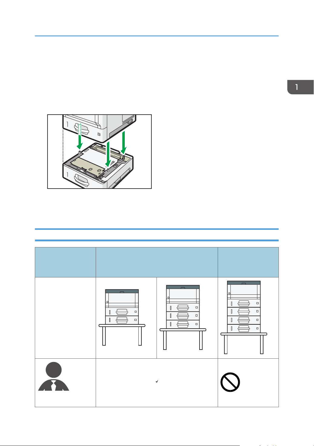
5. There are three upright pins on the optional paper feed unit. Align them with the holes on
the underside of the machine, and then carefully lower the machine.
6. Plug in the power cord, and then turn on the machine.
7. Print the configuration page to confirm that the unit was attached correctly.
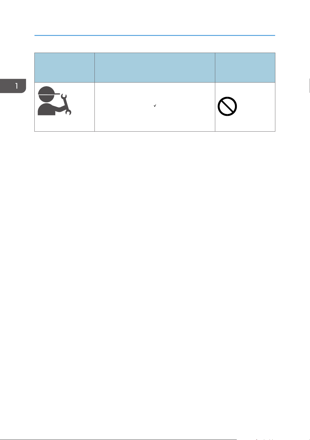
The number of tray that you can install
Use on table: printer
and three optional
paper feed units
Person who install
Use on table: printer and one or two optional
paper feed units
*1
User
27
Page 30
1. Getting Started
Person who install
Use on table: printer and one or two optional
paper feed units
Customer engineer
*1
A caster table is required to install three paper feed units on a machine.
Use on table: printer
and three optional
paper feed units
*1
28
Page 31

65
31
2
4
DYR157
Installing the Hard Disk
Installing the Hard Disk
By installing options, you can improve machine performance and expand the available features.
• Before beginning work, ground yourself by touching something metal to discharge any static
electricity. Static electricity can damage the interface units.
• Do not subject the interface units to physical shocks.
1. Check the contents of the package.
1. Hard disk
2. Flat cable
3. Power cord
4. Screw (2)
5. Inner cover
6. Memory cover
2. Turn the machine off and unplug the power cord.
29
Page 32

DYR158
DYR159
1
2
DYR160
1. Getting Started
3. Remove the memory cover.
4. Loosen the screw by using a coin, and then remove the inner cover.
30
5. Install the hard disk in the indicated position.
Page 33

DYR161
DYR162
DYR163
Installing the Hard Disk
6. Connect the flat cable and power cord to the hard disk.
7. Align the upper protrusions on the hard disk into the notches on the machine, and then
fasten the hard disk to the machine with the screw.
31
Page 34

DYR164
DYR165
DYR166
1. Getting Started
8. Connect the flat cable and power cord to the board of the machine.
9. Insert the two protrusions of the supplied inner cover, and then the lower protrusion, into
the notches on the machine.
10. Tighten the screw.
32
Page 35

DYR167
Installing the Hard Disk
11. Attach the memory cover.
12. Plug in the power cord, and then turn on the machine.
When you switch the power on, a message is displayed indicating that the external hard disk drive
will be formatted.
13. Print the configuration page to confirm the installation.
If it is correctly installed, "Hard Disk" will appear for "Device Connection" on the configuration
page.
33
Page 36

DYR213
DYR214
1. Getting Started
Installing the Wireless LAN interface board
• Before beginning work, ground yourself by touching something metal to discharge any static
electricity. Static electricity can damage the interface units.
• Do not subject the Wireless LAN interface board to physical shocks.
1. Check the contents of the package.
2. Turn the machine off and unplug the power cord.
3. Loosen the two screws and remove the slot cover.
The removed cover will not be reused.
4. Fully insert the interface board.
Confirm that the interface board is firmly connected to the controller board.
5. Tighten the two screws to secure the interface board.
6. Plug in the power cord, and then turn on the machine.
7. Print the configuration page to confirm that the board was attached correctly.
After installing the Wireless Interface board, see page 13 "Setting Wireless LAN" to specify the
wireless LAN settings.
34
Page 37

DYR213
DYR215
Installing the IEEE 1284 interface board
Installing the IEEE 1284 interface board
• Before beginning work, ground yourself by touching something metal to discharge any static
electricity. Static electricity can damage the interface units.
• Do not subject the IEEE 1284 interface board to physical shocks.
1. Check the contents of the package.
2. Turn the machine off and unplug the power cord.
3. Loosen the two screws and remove the slot cover.
The removed cover will not be reused.
4. Fully insert the IEEE 1284 interface board.
Confirm that the IEEE 1284 interface board is firmly connected to the controller board.
5. Tighten the two screws to secure the interface board.
6. Plug in the power cord, and then turn on the machine.
7. Print the configuration page to confirm that the board was attached correctly.
35
Page 38

DYR216
1. Getting Started
Connecting to the IEEE 1284 Interface
This section describes how to connect an IEEE 1284 interface cable to the optional IEEE 1284 interface
board.
This machine does not come with an IEEE 1284 interface cable. Make sure you purchase the
appropriate cable for the machine (connector shape) and your computer.
Use a five meter (197 inch) or shorter IEEE 1284 compatible cable whose performance is guaranteed
on the host computer.
1. Make sure the main power switch on the machine is off.
2. Turn off the main power switch of the host computer.
3. Connect an IEEE 1284 interface cable to the IEEE 1284 port.
36
You might have to use a conversion adapter to connect the cable to the interface. For details about
acquiring a conversion adapter, consult your sales or service representative.
4. Connect the other end of the cable into the interface connector on the host computer.
Before connecting the cable to the computer, check the shape of the connector. Connect the cable
firmly.
5. Turn on the main power switch of the machine.
6. Turn on the host computer.
When using Windows 7/8.1/10 and Windows Server 2008/2008 R2/2012/2012
R2/2016, a printer driver installation screen might appear when the computer is turned on. If this
happens, click [Cancel] on the screen.
Page 39

DYR213
DYR218
Installing the USB device server
Installing the USB device server
• Before beginning work, ground yourself by touching something metal to discharge any static
electricity. Static electricity can damage the interface units.
• Do not subject the USB device server to physical shocks.
The optional USB device server is an interface board that adds an Ethernet port to the machine.
With this option installed, two Ethernet cables can be connected at the same time using the standard port
on the machine and an additional port on the USB device server. You can assign different IP addresses
to each port, so the machine can print jobs from different network segments.
Procedure for installing the USB device server
1. Check the contents of the package.
2. Turn the machine off and unplug the power cord.
3. Loosen the two screws and remove the slot cover.
The removed cover will not be reused.
4. Fully insert the interface board.
37
Page 40

1. Getting Started
Check that the interface board is firmly connected to the controller board.
5. Tighten the two screws to secure the interface board.
6. Connect the USB device server to the machine.
For details, see the Setup Guide provided with the USB device server.
Connecting to the Extra Ethernet Interface with the USB Device Server Option
This section describes how to connect an Ethernet interface cable to the Ethernet port of the optional USB
Device Server.
USB Device Server Option is an interface board for adding an extra Ethernet port. If you install USB
Device Server Option, you can connect two Ethernet cables simultaneously: one to the machine's
Ethernet port and one to the Ethernet port of USB Device Server Option. An IP address can be assigned
to each connection, and you can use one machine to print from different network segments.
Remove the cover of USB2.0 port on the machine and connect the port to the USB port of the USB
device server.
• A network interface cable with a ferrite core must be used for RF interference suppression.
• Use the following Ethernet cables.
• When using 100BASE-TX/10BASE-T:
Unshielded Twisted Pair Cable (UTP) or Shielded Twisted Pair Cable (STP) and Category type
5 or more
• When using 1000BASE-T:
Unshielded Twisted Pair Cable (UTP) or Shielded Twisted Pair Cable (STP) and Category type
5e or more
1. Make sure the main power switch is turned off.
38
Page 41

1
1
BZU010
DYR219
Installing the USB device server
2. Make a loop at a distance of a few centimeters (1) from each end of the Ethernet interface
cable, and then attach to each loop the ferrite core provided with the USB Device Server
Option.
3. Connect the Ethernet interface cable to the Ethernet port of the USB Device Server Option.
You can use either a straight or crossover Ethernet cable for connecting to the USB Device Server
Option.
4. Connect the other end of the Ethernet interface cable to a network connection device such
as a hub.
It may take several seconds for the machine to recognize the USB Device Server Option. If you
have disconnected the USB cable, connect the USB cable again.
39
Page 42

DYQ550
1
2
3
1. Getting Started
5. Turn on the main power switch of the machine.
1. Indicator (orange)
When 100BASE-TX is operating, the LED is lit orange.
2. Indicator (green)
When 10BASE-T is operating, the LED is lit green.
3. Indicators (both orange and green)
When 1000BASE-T is operating, both LEDs are lit.
Specifying an IP address for the USB Device Server
Specify the IP address for the USB device server manually.
You can share the machine among multiple networks by specifying an IP address of a segment different
from that of the machine.
The default network settings of the USB device server are as follows:
• DHCPv4: Disable
• IPv4 address: 192.168.100.100
• Subnet Mask: 255.255.255.0
• Default Gateway: 0.0.0.0
• Network PnP: Enable
• mDNS: Enable
• LAN Interface: Auto
• Primary WINS Server: 0.0.0.0
• Secondary WINS Server: 0.0.0.0
To change the IP address for the USB device server, access the setting screen for the machine using a
web browser. For details about the setting items, see the USB device server's Help.
40
Page 43

DDE015
Installing the USB device server
• To use the USB device server in an IPv6 environment, it is necessary to change the network settings
in an IPv4 environment first.
• The machine status does not appear on your computer because the USB device server does not
support bidirectional communication.
• You cannot set the IP address for the USB device server using the control panel of the machine.
• The default administrator password is not specified. It is recommended that you specify the
administrator password on the [Maintenance Information] screen by using up to seven
alphanumeric characters.
• If you forget the IP address of the USB device server or have changed it from its default, follow the
procedure below to initialize the USB device server settings:
1. Turn off the main power of the machine.
2. Press and hold the switch on the interface using a pointed tool such as a pen, and turn on the
machine.
3. Both the upper and lower LEDs of the Ethernet port light up. Be sure to check the upper LED
turns off and the lower LED lights up in yellow, and then release the switch.
• Confirm the IP address of your computer before starting setup. The default IP address for the USB
device server is "192.168.100.100", and the default subnet mask is "255.255.255.0". To
perform the initial setup of the USB device server, set the IP address for your computer to
"192.168.100.XXX" (set XXX to any number, other than 100, from 0 to 255), and the subnet mask
to "255.255.255.0". It is recommended to make a note of the current IP address before changing
it.
1. Enter "http://192.168.100.100/" in the address bar of the Web to access the setting
screen of the machine.
2. Click [Network Settings].
3. Enter "root" as the user name, and then click [OK].
41
Page 44

1. Getting Started
4. Specify the IP address, Subnet Mask, and Default Gateway.
When DHCP is enabled, the IP address can be obtained automatically from a network device with
the DHCP server function.
5. Configure the other settings as necessary, and then click [Submit].
6. Exit the web browser.
7. Disconnect the Ethernet interface cable from the computer used for setup, and then
connect the cable to a network device, such as a hub.
8. Set the IP address of the USB device server in the printer driver used for printing.
• The USB device server does not support "Quick Install" and installation using the
SmartDeviceMonitor for Client port. A port must be set independently when a printer driver is
installed.
• To print using Port 9100 or LPR, see Driver Installation Guide and make the following settings:
1. Specify the IP address for the USB device server using the "Add Standard TCP/IP Printer Port
Wizard".
2. Select "Custom" for the device type.
3. For Port 9100, select "Raw" as the protocol, and then specify "9100" for the port number. For
LPR, select "LPR" as the protocol, and then specify "lp" as the queue name.
• For IPP printing, see "Using the IPP port", Driver Installation Guide. To specify the URL of the
machine during the procedure for adding printers, enter "http://(IP address of the USB device
server) /ipp/lp".
42
Page 45

DYR221
DYR222
Installing SD Card Options
Installing SD Card Options
• Keep SD cards out of reach of children. If a child swallows a SD card, consult a doctor
immediately.
• Do not subject the card to physical shocks.
1. Turn the machine off and unplug the power cord.
2. Loosen the screw and remove the SD card slot cover at an angle.
3. Insert the SD card into the slot until it clicks.
If you want to use three or more SD cards simultaneously, contact your service representative.
If you use a commercially available SD card for buck up the address book, insert the SD card to
lower slot.
43
Page 46

DYR223
1. Getting Started
4. Hook the SD card slot cover onto the opening, attach it flat against the controller board,
and then fasten it using the screw.
5. Plug in the power cord, and then turn on the machine.
6. Confirm that the SD card was installed correctly.
44
Page 47

DYR229
1
2
3
4
5
678
9
10
11
12
Guide to the Names and Functions of the Control Panel
Guide to the Names and Functions of the
Control Panel
1. Display
Displays current machine status and error messages.
Entering energy saver mode turns off the back light. For details about energy saver mode, see "Saving
Energy", For First-time Users.
2. Selection keys
Correspond to the function items at the bottom line on the display.
3. Scroll keys
Press these keys to move the cursor in each direction.
45
Page 48

1. Getting Started
When the [ ] [ ] [ ] [ ] keys appear in this manual, press the applicable key for the direction that you want
to move the cursor.
4. [OK] key
Use this key to confirm settings or setting values, or move to the next menu level.
5. [Escape] key
Press this key to cancel an operation or return to the previous display.
6. Main Power indicator
Lights up when the machine is ready to receive data from a computer. Flashes when the machine is warming
up or receiving data. It is unlit when the power is off or when the machine is in energy saver mode.
7. Alert indicator
Lights up or flashes when a machine error occurs.
Steady red: paper is jammed, consumables need to be replaced, or a malfunction has occurred.
Flashing yellow: consumables need to be replaced soon, printing is not possible, or printing is possible but
high print quality cannot be achieved.
Follow the instructions that appear on the display.
8. Data in indicator
Flashes when the machine is receiving data from a computer. The data in indicator is lit if there is data to be
printed.
9. [Suspend/Resume] key
Press this to suspend the print job currently being processed. The indicator remains lit as long as the job is
suspended.
To resume the job, press this key again. The suspended job will resume automatically when the time specified
in [Auto Reset Timer] elapses (default: 60 seconds).
For details about the [Auto Reset Timer] setting, see "Timer Settings", Settings.
10. [Job Reset] key
Press to cancel the current print job.
11. [Menu] key
Press this key to configure and check the current machine settings.
Press to change the default settings to meet your requirements.
12. [Switch Functions] key
Press this key to switch between the operation screen of the printer function and the function screens of the
extended features currently in use.
46
Page 49

CYN901
Guide to the Names and Functions of the Control Panel Screen
Guide to the Names and Functions of the
Control Panel Screen
1. Operational Status or Messages
Displays the machine status and messages.
2. Option
Press to display the following items:
• Form Feed
• Error Log
3. [Prt.Jobs]
Press to display print jobs sent from a computer.
[Prt.Jobs] is displayed only when the optional hard disk is installed in the machine.
4. [Supplies]
Press to display the information about machine supplies.
47
Page 50

1. Getting Started
Turning On/Off the Power
• When you push the main power switch, wait at least 0.5 seconds after it is confirmed that the main
power indicator has lit up or gone out.
The main power switch is on the front left side of the machine. When this switch is turned on, the main
power turns on and the main power indicator on the right side of the control panel lights up. When this
switch is turned off, the main power turns off and the main power indicator on the right side of the control
panel goes out. When this is done, machine power is off.
This machine automatically enters Fusing Unit Off mode or Sleep mode if you do not use it for a while.
For details, see "Saving Energy", For First-time Users.
Turning On/Off the Main Power
• When disconnecting the power cord from the wall outlet, always pull the plug, not the cord.
Pulling the cord can damage the power cord. Use of damaged power cords could result in fire
or electric shock.
• Do not turn off the power while the machine is in operation.
• Do not hold down the main power switch while turning off the main power. Doing so forcibly turns
off the machine's power and may damage the hard disk or memory and cause malfunctions.
• If a power outage is planned for your work environment, such as turning off the power of your
building to do maintenance, turn off the main power in advance. If the power outage occurs while
the main power is turned on, it may cause a malfunction.
Turing on the main power
1. Make sure the power cord is firmly plugged into the wall outlet.
2. Push the main power switch.
The main power indicator goes on.
48
Page 51

DYR168
Turning On/Off the Power
Turning off the main power
1. Push the main power switch.
The main power indicator goes out. The main power turns off automatically when the machine shuts
down. If the screen on the control panel does not disappear, contact your service representative.
49
Page 52

1. Getting Started
Logging In the Machine
To log in to the machine while user authentication is enabled, enter your user name, password, and or
user code according to the authentication method.
• Individual Authentication
If Basic Authentication, Windows Authentication, or LDAP Authentication is enabled, enter the
Login User Name and Login Password to log in.
• User Code Authentication
If User Code Authentication is enabled, enter the User Code to log in.
• Ask the user administrator for the Login User Name, Login Password, and User Code. For details
about user authentication, see "Configuring User Authentication", Security.
• User Code to enter on User Code Authentication is the numerical value registered in the Address
Book as "User Code".
User Code Authentication Using a Printer Driver
This section explains the procedure for logging in to the printer using a printer driver while User Code
Authentication is active.
If User Code Authentication is active, specify the user code in the printer properties of the printer driver.
For details, see the printer driver Help.
Logging In/Out Using the Control Panel
This section explains the procedure for logging in to the machine when Basic Authentication, Windows
Authentication, or LDAP Authentication is set.
When User Code Authentication is active, see page 50 "User Code Authentication Using a Printer
Driver".
• To prevent use of the machine by unauthorized persons, always log out when you have finished
using the machine.
Logging In Using the Control Panel
1. Press the [Menu] key.
2. Press the selection key beneath [Login].
50
3. Press the selection key beneath [Enter].
Page 53

Logging In the Machine
4. Press the [ ] , [ ] , [ ] or [ ] key to select the user name, and then press the [OK]
key to enter it.
5. Press the selection key beneath [Accept].
6. Press the selection key beneath [Enter].
7. Press the [ ] , [ ] , [ ] or [ ] key to select a password, and then press the [OK] key
to enter it.
8. Press the selection key beneath [Accept].
Logging Out Using the Control Panel
1. Press the [Menu] key.
2. Press the selection key beneath [Logout].
3. Press the selection key beneath [Yes].
• If authentication fails, the "Authentication failed." message appears. Check that the Login User
Name and Login Password are correct.
51
Page 54

1. Getting Started
52
Page 55

2. Print
DZC992
This chapter describes frequently used printer functions and operations. For information not included in
this chapter, see Print available on our website.
Installing the Printer Driver for Network Connection (Windows)
When the machine and the computer are connected to the same network, the installer searches for the
machine to install the printer driver. If the installer cannot find the machine, specify the IP address or
machine name to install the printer driver.
Installing the PCL 6 Printer Driver from the CD-ROM
1. Set the CD-ROM in the computer.
If the installer does not start automatically, double-click [Setup.exe] in the root directory of the CDROM.
2. Select a language, and then click [OK].
3. Click [Install from Disk].
4. Click [Network Printer(s)].
53
Page 56

DZC081
DZC080
2. Print
5. On the "License Agreement" screen, select [I accept the agreement.], and then click
[Next].
6. Confirm the "Confirm Network Connection" screen, and then click [Next].
The search detects devices connected to the network.
7. Select this machine from among the devices, and then click [Install].
54
8. If the "Set Port" screen is displayed, select the setting method of the port.
This screen is displayed when the computer cannot access the machine.
Page 57

Installing the Printer Driver for Network Connection (Windows)
Specify the port to use for the connection between the computer and machine using one of the
following methods:
To specify the IP address
1. Enter the IP address of the machine, and then click [Next].
2. Proceed to Step 9.
To select from the port list
1. Select the port to use for the connection between the computer and machine, and then
click [Next].
2. Proceed to Step 9.
To create a new port
1. Select [Specify a new port], and then click [Next].
2. On the "Add Printer and Utility Wizard" screen, select [Standard TCP/IP Port] and click
[Next].
3. On the "Add Standard TCP/IP Printer Port Wizard" screen, click [Next].
4. On the "Add port" screen, enter the printer name or IP address of the machine, and then
click [Next].
The port name is automatically entered. You can change the port name.
5. When the "Additional port information required" screen is displayed, select [RICOH
Network Printer C model], and then click [Next].
6. Click [Finish].
9. Specify the name of the printer to install, and whether to use it as the default printer.
55
Page 58

2. Print
10. Click [Continue].
Printer driver installation starts.
11. Click [Finish].
When you are prompted to restart your computer, restart it by following the instructions that
appear.
56
Page 59

DZC992
Installing the Printer Driver for USB Connection (Windows)
Installing the Printer Driver for USB Connection
(Windows)
When you connect the machine and the computer with a USB cable, the installer searches for the
machine to install the printer driver.
• Follow the instructions of the installer to connect the USB cable.
Installing the Printer Driver from the CD-ROM
1. Set the CD-ROM in the computer.
If the installer does not start automatically, double-click [Setup.exe] in the root directory of the CDROM.
2. Select a language, and then click [OK].
3. Click [Install from Disk].
4. Click [USB printer(s)].
57
Page 60

DZC081
DZC092
2. Print
5. On the "License Agreement" screen, select [I accept the agreement], and then click
[Next].
6. Select [Add a new printer], and then click [Next].
7. Select this machine from among the devices, and then click [Next].
58
8. Disconnect the USB cable from the machine and turn off the power of the machine, and
then click [Next].
Printer driver installation starts.
Page 61

Installing the Printer Driver for USB Connection (Windows)
9. Following the instructions on the "Auto-detect USB Port" screen, connect the machine and
the computer with the USB cable, and then turn on the power of the machine.
• The search detects the machine connected by the USB cable.
• If the machine is not detected, click [Stop Auto-detecting]. Even if the connection is canceled,
the installation is complete. After the installer screen is closed, the machine is added
automatically when it is connected to the computer with the USB cable.
10. Click [Finish].
59
Page 62

2. Print
Displaying the Printer Driver Properties
This section explains how to open the printer driver properties from [Control Panel].
• Manage Printers permission is required to change the printer settings. Log on as an Administrators
group member.
• You cannot change the machine default settings for individual users. Settings made in the printer
properties dialog box are applied to all users.
1. Right-click the [Start] menu, click [Control Panel].
2. Click [View devices and printers].
3. Right-click the icon of the printer you want to use.
4. Click [Printer properties].
60
Page 63

Standard Printing
Standard Printing
• Duplex printing is selected as the default setting. If you want to print on only one side, select [Off]
for the two-sided printing setting.
• If you send a print job via USB 2.0 while the machine is in Sleep mode, an error message might
appear when the print job is complete. In this case, check if the document was printed.
When Using the PCL 6 Printer Driver
1. Click the menu button of the application you are using, and then click [Print].
2. Select the printer you want to use.
3. Click [Preferences].
4. Select the [Frequently Used Settings] tab.
61
Page 64

2. Print
5. In the "Job Type:" list, select [Normal Print].
6. In the "Document Size:" list, select the size of the original to be printed.
62
Page 65

Standard Printing
7. In the "Orientation" area, select [Portrait] or [Landscape] as the orientation of the
original.
8. In the "Paper Type:" list, select the type of paper that is loaded in the paper tray.
63
Page 66

2. Print
9. In the "Input Tray:" list, select the paper tray that contains the paper you want to print
onto.
If you select [Auto Tray Select] in the "Input Tray:" list, the paper tray is automatically selected
according to the paper size and type specified.
10. If you want to print multiple copies, specify a number of sets in the "Copies:" box.
11. Click [OK].
12. Start printing from the application's [Print] dialog box.
64
Page 67

Printing on Both Sides of Sheets
Printing on Both Sides of Sheets
This section explains how to print on both sides of each page using the printer driver.
• The paper types that can be printed on both sides are as follows:
• Plain & Recycled, Plain 1 (66 to 74 g/m2), Plain 2 (75 to 90 g/m2), Recycled, Special 1,
Middle Thick (91 to 105 g/m2), Thick 1 (106 to 130 g/m2), Thick 2 (131 to 162 g/m2),
Thin (52 to 65 g/m2), Letterhead
How to Print on Both Sides of the Paper (When Using the PCL 6 Printer Driver)
1. Click the menu button of the application you are using, and then click [Print].
2. Select the printer you want to use.
3. Click [Preferences].
4. Click the [Frequently Used Settings] tab.
You can also click the [Detailed Settings] tab, and then click [2 Sided/Layout/Booklet] in the
"Menu:" box.
5. Select the method for binding the output pages in the "2 sided:" list.
You can select which way the bound pages open by specifying which edge to bind.
Orientation Long Edge Bind Short Edge Bind
Portrait
Landscape
6. Change any other print settings if necessary.
7. Click [OK].
8. Start printing from the application's [Print] dialog box.
65
Page 68

2. Print
Combining Multiple Pages into Single Page
This section explains how to print multiple pages onto a single sheet. The combine printing function
allows you to economize on paper by printing multiple sheets at reduced size onto a single sheet.
How to Print Multiple Pages onto a Single Sheet (When Using the PCL 6 Printer Driver)
1. Click the menu button of the application you are using, and then click [Print].
2. Select the printer you want to use.
3. Click [Preferences].
4. Click the [Frequently Used Settings] tab.
You can also click the [Detailed Settings] tab, and then click [2 Sided/Layout/Booklet] in the
"Menu:" box.
5. Select the combination pattern in the "Layout:" list, and then specify the method for
combining pages in the "Page Order:" list.
This function allows you to print 2, 4, 6, 9, or 16 pages at reduced size onto a single sheet and to
specify a page ordering pattern for the combination. When combining 4 or more pages onto a
single sheet of paper, four patterns are available.
The following illustrations show example page ordering patterns for 2- and 4-page combinations.
2 Pages per Sheet
Orientation
Portrait
Landscape
From Left to Right/Top to
Bottom
From Right to Left/Top to
Bottom
66
Page 69

Combining Multiple Pages into Single Page
4 Pages per Sheet
Right, then Down Down, then Right Left, then Down Down, then Left
To draw a border line around each page, select the [Draw Frame Border] check box in [2 Sided/
Layout/Booklet] in the [Detailed Settings] tab.
6. Change any other print settings if necessary.
7. Click [OK].
8. Start printing from the application's [Print] dialog box.
67
Page 70

2. Print
Printing on Envelopes
Configure the paper settings appropriately using both the printer driver and the control panel.
Configuring Envelope Settings Using the Control Panel
After configuring the envelope settings on the control panel, configure the printer driver settings.
For details, see page 68 "Printing on Envelopes Using the Printer Driver".
1. Press the [Menu] key.
2. Press the [ ] or [ ] key to select [Paper Input], and then press the [OK] key.
3. Press the [ ] or [ ] key to select [Paper Size: (tray name)], and then press the [OK] key.
4. Press the [ ] or [ ] key to select the envelope type, and then press the [OK] key.
5. Press the [Escape] key.
6. Press the [ ] or [ ] key to select [Maintenance], and then press the [OK] key.
7. Press the [ ] or [ ] key to select [General Settings], and then press the [OK] key.
8. Press the [ ] or [ ] key to select [Envelope Setting], and then press the [OK] key.
9. Press the [ ] or [ ] key to select the source tray for which you want to change the paper
thickness, and then press the [OK] key.
10. Press the [ ] or [ ] key to select the paper thickness, and then press the [OK] key.
Printing on Envelopes Using the Printer Driver
Before configuring envelope settings in the printer driver, configure the control panel settings.
For details see page 68 "Configuring Envelope Settings Using the Control Panel".
1. Click the menu button of the application you are using, and then click [Print].
2. Select the printer you want to use.
3. Click [Preferences].
4. In the "Document Size:" list, select the envelope size.
When using the PCL 5e printer driver, click the [Paper] tab, and then select the bypass tray in the
"Input Tray:" list.
5. In the "Input Tray:" list, select the paper tray where the envelopes are loaded.
6. In the "Paper Type:" list, select [Envelope].
7. Change any other print settings if necessary.
68
8. Click [OK].
Page 71

9. Start printing from the application's [Print] dialog box.
Printing on Envelopes
69
Page 72

2. Print
70
Page 73

3. Web Image Monitor
1
2
3
4
5
DYR407
This chapter describes frequently used Web Image Monitor functions and operations. For information
not included in this chapter, see Connecting the Machine/ System Settings available on our website or
Web Image Monitor Help.
Displaying Top Page
This section explains the Top Page and how to display Web Image Monitor controlled from networked
computers. (Web Image Monitor is a management tool installed on this machine to monitor this machine
or configure settings for this machine by using a web browser.)
If user authentication is activated, you are required to enter your login user name and password to use
Web Image Monitor. For Details, "Logging In/Out Using Web Image Monitor", For First-time Users.
• When entering an IPv4 address, do not begin segments with zeros. For example: If the address is
"192.168.001.010", you must enter it as "192.168.1.10".
1. Start a web browser from a networked computer.
2. Enter "http://(machine's IP address or host name)/" in your web browser's URL bar.
Top Page of Web Image Monitor appears.
If the machine's host name has been registered on the DNS or WINS server, you can enter it.
When setting SSL, a protocol for encrypted communication, under environment which server
authentication is issued, enter "https://(machine's IP address or host name)/".
Web Image Monitor is divided into the following areas:
1. Menu area
If you select a menu item, its content will be shown.
71
Page 74

3. Web Image Monitor
2. Header area
Display icons for the links to Help and the keyword search function. This area also displays [Login] and
[Logout], which allows you to switch between the administrator and guest mode.
3. Refresh/Help
(Refresh): Click at the upper right in the work area to update the machine information. Click the web
browser's [Refresh] button to refresh the entire browser screen.
(Help): Use Help to view or download Help file contents.
4. Basic Information area
Display the basic information of the machine.
5. Work area
Display the contents of the item selected in the menu area.
72
Page 75

4. Adding Paper and Toner
This chapter describes how to load paper into the paper tray and recommended paper sizes and types.
Loading Paper
• When loading paper, take care not to trap or injure your fingers.
• If one or more paper feed trays are installed, do not pull out more than one tray at a time
when you are changing or replenishing paper or resolving paper jams. Pressing down
forcefully on the machine's upper surfaces can result in malfunctions and/or user injury.
• Do not stack paper over the limit mark.
• If multiple sheets are fed at one time, fan the paper before loading it.
• If you load paper when only a few sheets of paper remain in the tray, multiple sheet feeding may
occur. Remove any remaining paper, stack them with the new sheets of paper, and then fan the
entire stack before loading it into the tray.
• Straighten curled or warped paper before loading.
• For details about the paper sizes and types that can be used, see "Recommended Paper",
Specifications.
• You might at times hear a rustling noise from paper moving through the machine. This noise does
not indicate a malfunction.
• If thin paper jams, decrease the amount of paper set in the tray, and then try printing again.
• When the condition of the cut edge of the paper is bad, a burr may form at the edge of the paper.
When you use paper that has a burr, the orientation of the burr at the leading edge of the paper
may reduce the print quality at the leading edge of the paper.
Loading Paper into Paper Trays
Every paper tray is loaded in the same way.
In the following example procedure, paper is loaded into Tray 1.
• If a paper tray is pushed vigorously when putting it back into place, the position of the tray's side
fences and end fence may slip out of place.
73
Page 76

DVL540
2
1
3
DYR169
4. Adding Paper and Toner
• When loading a low number of sheets, be sure not to squeeze the side fences and end fence in too
tightly. If the side fences are squeezed too tightly against the paper, the edges may crease or the
paper may misfeed.
Guide to names of paper tray
1. End fence
2. Side fence
3. Paper size dial
1. Pull the paper tray carefully until it stops. Lift the front side of the tray, and then pull it out
of the machine.
74
Page 77

DVL402
DVL403
A5
DVL401
Loading Paper
2. Pinch the lever of the back fence and align it with the paper size. Next, pinch the lever of
the right fence and align the right and left fences with the paper size.
3. Load the new paper stack print side down.
Do not stack paper over the limit mark.
4. Rotate the paper size dial, which is located at the front right of the tray, so that the size
and the feed direction of the paper in the paper tray can be seen from the window.
75
Page 78

DYR170
4. Adding Paper and Toner
5. Lifting the front side of the tray, insert it into the machine, and then push it in carefully until
it stops.
• While you are printing, a message informing you that the size of the paper that is loaded and the
print setting are different may appear. To change the paper size, select [Job Reset] and load the
correct size paper, and then try printing again. To not change the paper size, select [Loaded
Paper].
• A message informing you that the size of the loaded paper and the print settings are different may
appear if multiple sheets are fed at one time. If this happens, take out the loaded paper, fan it, turn
it over, load it again, and then select [Loaded Paper].
• Various sizes of paper can be loaded in the paper by adjusting the positions of side fences and
end fence. For details, see "Changing Paper Size Settings", For First-time Users.
• Select appropriate paper thickness for the loaded paper.
• When printing with [Thick Paper 3], remove printed sheets one by one.
Loading Paper into the Bypass Tray
Use the bypass tray to use OHP transparencies, adhesive labels, translucent paper, and paper that
cannot be loaded in the paper trays.
• The maximum number of sheets you can load at the same time depends on paper type. Do not
stack paper over the limit mark. For the maximum number of sheets you can load, see
"Recommended Paper", Specifications.
76
Page 79

1. Open the bypass tray.
DYQ114
DYR172
B
A
DYR173
2. Slide the paper guidesA and the extenderB to full size.
Loading Paper
3. Load the paper face up until you hear the beep.
4. Align the paper guides to the paper size.
If the guides are not flush against the paper, images might be skewed or paper misfeeds might
occur.
77
Page 80

DYR174
4. Adding Paper and Toner
• While you are printing, a message informing you that the size of the paper that is loaded and the
print setting are different may appear. To change the paper size, select [Job Reset] and load the
correct size paper, and then try printing again. To not change the paper size, select [Loaded
Paper].
• A message informing you that the size of the loaded paper and the print settings are different may
appear if multiple sheets are fed at one time. If this happens, take out the loaded paper, fan it, turn
it over, load it again, and then select [Loaded Paper].
• When you use the bypass tray, it is recommended to load the paper so that the paper will be fed
from its short edge.
• Select appropriate paper thickness for the loaded paper.
• When loading label paper:
• It is recommended to place one sheet at a time.
• Select the appropriate paper thickness for [Paper Type] in [Paper Input].
• When loading OHP transparencies:
• It is recommended to place one sheet at a time.
• When printing on OHP transparencies from the computer, specify OHP transparencies for the
paper type.
• Fan OHP transparencies thoroughly whenever you use them. This prevents OHP
transparencies from sticking together, and from feeding incorrectly.
• Remove printed sheets one by one.
• When loading translucent paper:
• When loading translucent paper, always use long grain paper, and set the paper direction
according to the grain.
• Translucent paper easily absorbs humidity and becomes curled. Remove curl in the translucent
paper before loading.
78
• Remove printed sheets one by one.
Page 81

Loading Paper
• If a paper jam occurs or if the machine makes a strange noise when feeding stacks of coated
paper, feed the coated paper from the bypass tray one sheet at a time.
• Letterhead paper must be loaded a specific orientation. For details, see page 79 "Loading
Orientation-fixed Paper or Two-sided Paper".
• You can load envelopes into the bypass tray. Envelopes must be loaded in a specific orientation.
For details, see "When Loading Envelopes", Specifications.
• When [Notification Sound] is set to [No Sound], it does not sound if you load paper into the
bypass tray. For details about [Notification Sound], see "Screen Features", Settings.
• When printing with [Thick Paper 3], remove printed sheets one by one.
Loading Orientation-fixed Paper or Two-sided Paper
Orientation-fixed (top to bottom) or two-sided paper (for example, letterhead paper, punched paper, or
copied paper) might not be printed correctly, depending on how the paper is placed.
Settings using the control panel
Set [Letterhead Setting] to [Auto Detect] or [On (Always)], and then place the paper as shown in
the table below. For details about [Letterhead Setting], see "System", Print.
Paper orientation
The meanings of the icons are as follows:
Icon Meaning
• Printer mode
Print side Paper trays Bypass tray
One-sided
Place or load paper printed side face up.
Place or load paper printed side face down.
79
Page 82

4. Adding Paper and Toner
Print side Paper trays Bypass tray
Two-sided
• To print on letterhead paper when [Auto Detect] is specified for [Letterhead Setting], you must
specify [Letterhead] as the paper type in the printer driver's settings.
• If a print job is changed partway through printing from one-sided to two-sided printing, one-sided
output after the first printing may be printed facing a different direction. To ensure all paper is
output facing the same direction, specify different input trays for one-sided and two-sided printing.
Note also that two-sided printing must be disabled for the tray specified for one-sided printing.
• For details about how to make two-sided prints, see "Printing on Both Sides of Sheets", Print.
80
Page 83

Recommended Paper
Recommended Paper
This section describes recommended paper sizes and types.
• If you use paper that curls, either because it is too dry or too damp, a staple clogging or paper jam
may occur.
• Do not use paper designed for inkjet printers, as these may stick to the fusing unit and cause a
misfeed.
• When you load OHP transparencies, check the front and back of the sheets, and place them
correctly, or a misfeed might occur.
Tray 1
Paper type and weight Paper size Paper capacity
52-220 g/m2 (14 lb. Bond 80 lb. Cover)
Thin Paper–Thick Paper 3
52-220 g/m2 (14 lb. Bond 80 lb. Cover)
Thin Paper–Thick Paper 3
52-220 g/m2 (14 lb. Bond 80 lb. Cover)
Thin Paper–Thick Paper 3
Select the paper size using
the paper size dial on the
tray*1:
A4 , A5 , A6 , 81/2 × 14
, 81/2 × 11 , 51/2 ×
81/
2
Set the paper size dial on the
tray to "Asterisk", and select
the paper size with the control
panel:
A5 , B5 JIS , B6 JIS ,
81/2 × 13 , 81/4 × 14 ,
81/4 × 13 , 8 × 13 , 8 ×
101/2, 8 × 10 , 71/4 ×
101/2, 16K , 81/2 ×
132/
5
Custom size:
Vertical: 148.0–356.0 mm
550 sheets
(When using Plain Paper 1)
550 sheets
(When using Plain Paper 1)
550 sheets
(When using Plain Paper 1)
Horizontal: 82.5–216.0 mm
Vertical: 5.83–14.01 inches
Horizontal: 3.25–8.50 inches
81
Page 84

4. Adding Paper and Toner
Paper type and weight Paper size Paper capacity
Envelopes Select the paper size:
41/8 × 91/2, 37/8 × 71/
*2
2
, 81/2 × 132/5, C5 Env
, C6 Env , DL Env
When a print job is performed on A5 or 5 1/2" × 8 1/2" paper, it is recommended to set the paper
*1
horizontally. While a print job is performed on paper that is loaded vertically, smearing may occur near
the edges of the printed paper. Also, use the bypass tray when printing on paper that is set horizontally.
*2 Do not stack over the limit mark. The number of sheets you can load in the paper tray varies
depending on the weight and condition of the paper.
Lower paper tray (250 sheets)
Paper type and weight Paper size Paper capacity
52-220 g/m2 (14 lb. Bond 80 lb. Cover)
Thin Paper–Thick Paper 3
Select the paper size using
the paper size dial on the
tray*1:
275 sheets
(When using Plain Paper 1)
A4 , A5 , A6 , 81/2 × 14
, 81/2 × 11 , 51/2 ×
81/
2
52-220 g/m2 (14 lb. Bond 80 lb. Cover)
Thin Paper–Thick Paper 3
Set the paper size dial on the
tray to "Asterisk", and select
the paper size with the control
275 sheets
(When using Plain Paper 1)
panel:
82
A5 , B5 JIS , B6 JIS ,
81/2 × 13 , 81/4 × 14 ,
81/4 × 13 , 8 × 13 , 8 ×
101/2, 8 × 10 , 71/4 ×
101/2, 16K , 81/2 ×
132/
5
Page 85

Recommended Paper
Paper type and weight Paper size Paper capacity
52-220 g/m2 (14 lb. Bond 80 lb. Cover)
Thin Paper–Thick Paper 3
Lower paper tray (500 sheets)
Paper type and weight Paper size Paper capacity
52-220 g/m2 (14 lb. Bond 80 lb. Cover)
Thin Paper–Thick Paper 3
52-220 g/m2 (14 lb. Bond 80 lb. Cover)
Thin Paper–Thick Paper 3
Custom size:
Vertical: 148.0–356.0 mm
Horizontal: 82.5–216.0 mm
Vertical: 5.83–14.01 inches
Horizontal: 3.25–8.50 inches
Select the paper size using
the paper size dial on the
tray*1:
A4 , A5 , A6 , 81/2 × 14
, 81/2 × 11 , 51/2 ×
81/
2
Set the paper size dial on the
tray to "Asterisk", and select
the paper size with the control
panel:
275 sheets
(When using Plain Paper 1)
550 sheets
(When using Plain Paper 1)
550 sheets
(When using Plain Paper 1)
A5 , B5 JIS , B6 JIS ,
81/2 × 13 , 81/4 × 14 ,
81/4 × 13 , 8 × 13 , 8 ×
101/2, 8 × 10 , 71/4 ×
101/2, 16K , 81/2 ×
132/
5
83
Page 86

4. Adding Paper and Toner
Paper type and weight Paper size Paper capacity
52-220 g/m2 (14 lb. Bond 80 lb. Cover)
Thin Paper–Thick Paper 3
Bypass tray
Paper type and weight Paper size Paper capacity
52-256 g/m2 (14 lb.
Bond-140 lb. Index)
Thin Paper-Thick Paper 3
Custom size:
Vertical: 148.0–356.0 mm
Horizontal: 82.5–216.0 mm
Vertical: 5.83–14.01 inches
Horizontal: 3.25–8.50 inches
Select the paper size*1:
A4 , A5 , A6 , B5 JIS ,
B6 JIS , B7 JIS , 81/2 ×
14 , 81/2 × 13 , 81/2 × 11
, 81/4 × 14 , 81/4 × 13 ,
8 × 13 , 8 × 101/2, 8 ×
10 , 71/4 × 101/2, 51/
× 81/
132/
, 16K , 81/2 ×
2
5
550 sheets
(When using Plain Paper 1)
• Thin Paper–Plain Paper
2: 100 sheets
• Middle Thick –Thick
Paper 3:
2
*3
84
52-256 g/m2 (14 lb.
Bond-140 lb. Index)
Thin Paper-Thick Paper 3
Vertical: 127.0–900.0 mm
Horizontal: 60.0–216.0 mm
Vertical: 5.00–35.43 inches
Horizontal: 2.37–8.50 inches
• Thin Paper–Plain Paper
2: 100 sheets
• Middle Thick –Thick
Paper 3:
*3
Page 87

Recommended Paper
Paper type and weight Paper size Paper capacity
Translucent paper A4 , A5 , A6 , B5 JIS ,
B6 JIS , B7 JIS , 81/2 ×
OHP transparencies
Label paper (adhesive labels) 1 sheet
14 , 81/2 × 13 , 81/2 × 11
, 81/4 × 14 , 81/4 × 13 ,
*5
*2
8 × 13 , 8 × 101/2, 8 ×
, 71/4 × 101/2, 51/
10
× 81/
2
132/
5
Custom size
, 16K , 81/2 ×
*4
2
Vertical: 127.0–900.0 mm
Horizontal: 60.0–216.0 mm
Vertical: 5.00–35.43 inches
Horizontal: 2.37–8.50 inches
Envelopes Select the paper size:
41/8 × 91/2, 37/8 × 71/
*4
2
, C5 Env , C6 Env , DL Env
When a print job is performed on A5 or 51/2" × 81/2" paper, it is recommended to load the paper
*1
horizontally. While a print job is performed on paper that is loaded vertically, smearing may occur near
the edges of the printed paper.
When loading OHP transparencies in the bypass tray, do not stack paper over the limit mark.
*2
When loading thick paper in the bypass tray, do not stack paper over the limit mark. The number of
*3
sheets you can load in the bypass tray varies depending on the weight and condition of the paper.
Load envelopes so that the height of the stack of envelopes does not exceed the limit mark of the bypass
*4
tray without pressing on the stack of envelopes.
When loading Translucent paper in the bypass tray, do not stack paper over the limit mark.
*5
Paper Thickness
Paper Thickness
*1
Thin Paper 52–65 g/m2 (14–18 lb. Bond)
Plain Paper 1 66–74 g/m2 (18–20 lb. Bond)
Paper weight
85
Page 88

4. Adding Paper and Toner
Paper Thickness
*1
Paper weight
Plain Paper 2 75–90 g/m2 (20–24 lb. Bond)
Middle Thick 91–105 g/m2 (24–28 lb. Bond)
Thick Paper 1 106–130 g/m2 (28-35 lb. Bond)
Thick Paper 2 131–162 g/m2 (35 lb. Bond–90 lb. Index)
Thick Paper 3 163–256 g/m2 (90 lb.Index-140 lb. Index)
Print quality will decrease if the paper you are using is close to the minimum or maximum weight.
*1
Change the paper weight setting to thinner or thicker.
• Certain types of paper, such as translucent paper or OHP transparencies, may produce noise
when delivered. This noise does not indicate a problem and print quality is unaffected.
• The paper capacity described in the tables above is an example. Actual paper capacity might be
lower, depending on the paper type.
• When loading paper, make sure the stack height does not exceed the limit mark of the paper tray.
• If multiple sheet feeding occurs, fan sheets thoroughly or load sheets one by one from the bypass
tray.
• Flatten out curled sheets before loading them.
• Depending on the paper sizes and types, the print speed may be slower than usual.
• When loading thick paper of 106–256 g/m2 (28 lb. Bond–140 lb. Index), see page 87
"When Loading Thick Paper".
• When loading envelopes, see page 88 "When Loading Envelopes".
• When printing onto letterhead paper, the paper placing orientation is different depending on
which function you are using. For details, see "Loading Orientation-fixed Paper or Two-sided
Paper", For First-time Users.
• When you are using 45K copy and print paper, loading the paper fully up to load limit mark (MAX
mark) may cause paper jams. Load the number of sheets of paper described below, as a guide.
• Lower paper tray (500 sheets)
• A4 : 500 sheets or less
• B5 : 500 sheets or less
• A5 : 250 sheets or less
• We recommend that you use the bypass tray when you use a paper size smaller than the sizes
above.
• Lower paper tray (250 sheets)
86
Page 89

Recommended Paper
• A4 : 250 sheets or less
• B5 : 250 sheets or less
• A5 : 125 sheets or less
• We recommend that you use the bypass tray when you use a paper size smaller than the sizes
above.
When Loading Thick Paper
This section gives you various details about and recommendations concerning thick paper.
• When loading thick paper of 106–256 g/m2 (28 lb. Bond–68 lb. Index) in the paper trays or
bypass tray, follow the recommendations below to prevent misfeeds and loss of image quality.
When loading thick paper of 106–163 g/m2 (28 lb. Bond–90 lb. Index) in the paper trays, or 106–
220 g/m2 (28 lb. Bond–80 lb. Cover) in the bypass tray, follow the recommendations below to
prevent misfeeds and loss of image quality.
• Store all your paper in the same environment - a room where the temperature is 20–25°C (68–
77°F) and the humidity is 30–65%.
• Jams and misfeeds can occur when printing on thick smooth paper. To prevent such problems, be
sure to fan smooth paper thoroughly before loading them. If paper continues to become jammed or
feed in together even after they are fanned, load them one by one from the bypass tray.
• When loading thick paper, set the paper direction according to its grain, as shown in the following
diagram:
Direction of paper grain Paper trays Bypass tray
• Select [Thick Paper 1] or [Thick Paper 2] as the paper thickness in [Paper Input].
• If Thin Paper, Thick Paper 1 (when in low temperature), Thick Paper 2, or Thick Paper 3 is selected,
the print speed may change.
87
Page 90

4. Adding Paper and Toner
• Even if thick paper is loaded as described above, normal operations and print quality might still not
be possible, depending on the paper type.
• Prints might have prominent vertical creases.
• Prints might be noticeably curled. Flatten out prints if they are creased or curled.
• When printing onto thick paper, the print speed changes.
When Loading Envelopes
This section gives you various details about and recommendations concerning envelopes.
• Do not use window envelopes.
• Fan the envelopes before loading them to separate them and prevent the glue on them from
causing them to stick together. If fanning does not prevent them sticking together, load them one by
one. Note that some types of envelopes cannot be used with this machine.
• Some kinds of envelope might cause misfeeds, wrinkles or print poorly.
• When loading envelopes in the orientation, load them with flaps closed.
• Before loading envelopes, press down on them to remove any air from inside, flatten out all four
edges. If they are bent or curled, flatten their leading edges (the edge going into the machine) by
running a pencil or ruler across them.
• When loading envelopes, do not stack paper over the limit mark. If you squeeze extra envelopes
into the bypass tray, misfeeds might occur.
In printer mode
The way to load envelopes varies depending on the orientation of the envelopes. When printing
onto envelopes, load them according to the applicable orientation shown below:
How to load envelopes
Types of
envelopes
Side-opening
envelopes
• Flaps: closed
• Bottom side of envelopes:
toward the left of the machine
• Side to be printed: face down
Tray 1
Bypass tray
• Flaps: closed
• Bottom side of envelopes:
toward the left of the machine
• Side to be printed: face up
88
Page 91

Recommended Paper
When loading envelopes, select "Envelope" as the paper types using both [Paper Input] and printer
driver and specify the thickness of envelopes. For details, see "Printing on Envelopes", Print.
To print on envelopes that are loaded with their short edges against the machine body, images
may not be printed appropriately. Change settings according to the function you use. Be sure to set
the original and paper appropriately.
To print on envelopes that are loaded with their short edges against the machine body, rotate the
print image by 180 degrees using the printer driver.
Recommended envelopes
For information about recommended envelopes, contact your local dealer.
For details about the sizes of envelopes you can load, see page 81 "Recommended Paper".
• Load only one size and type of envelope at a time.
• The Duplex function cannot be used with envelopes.
• To get better output quality, it is recommended that you set the leading-edge print margin to at least
15 mm (0.6 inches) and the other margins to at least 10 mm (0.4 inches) each.
• Output quality on envelopes may be uneven if parts of an envelope have differing thicknesses. Print
one or two envelopes to check print quality.
• Flatten out prints if they are creased or curled.
• Check the envelopes are not damp.
• High temperature and high humidity conditions can reduce print quality and cause envelopes to
become creased.
• Depending on the environment, envelopes may wrinkle them even if they are recommended.
• Certain types of envelopes might come out creased, dirtied, or misprinted. If you are printing a
solid color on an envelope, lines may appear where the overlapped edges of the envelope make it
thicker.
• When you print on envelope, the print speed may be slower than usual.
89
Page 92

4. Adding Paper and Toner
Adding Toner
This section explains precautions when replacing the print cartridge, procedures for replacing the print
cartridge, operations when toner has run out, and how to dispose of used print cartridge.
• Do not dispose of the following items into a fire. Toner will ignite on contact with naked flame
and burns can result.
• Toner (new or used)
• Toner containers while toner is inside
• Toner-attached parts
• Do not store toner (new or used) or toner containers while toner is inside in a place with an open
flame. The toner can ignite and result in burns or fire.
• Do not absorb spilled toner (including used toner) using a vacuum cleaner. Absorbed toner may
cause ignition or explosion due to electric contact sparks inside the vacuum cleaner. However,
you can use a toner-compatible industrial vacuum cleaner. When toner is spilled, remove the
spilled toner using a wet cloth so that the toner is not scattered.
• The following explains the warning messages on the plastic bag used in this product's
packaging:
• Do not leave the polythene materials (bags, etc.) supplied with this machine close to babies
and small children. Suffocation can result if polythene materials are brought into contact
with the mouth or nose.
• Do not open toner containers forcibly while toner is inside, crush or squeeze them. Toner
spillage can cause accidental ingestion or dirtying of clothes, hands, or floor.
• Do not leave the following items in a place where children can reach them:
• Toner (new or used)
• Toner containers while toner is inside
• Toner-attached parts
90
Page 93

Adding Toner
• When the following occurs while toner is handled, receive emergency measures first, and then
consult a doctor if necessary.
• When inhaling toner, gargle with a large amount of water and move into a fresh air
environment.
• When swallowing toner, dilute gastric contents with a large amount of water.
• When getting toner into your eyes, flush them with a large amount of water.
• When removing jammed paper, replenishing or replacing toner (new or used), be careful not to
have toner dirt your skin or clothes.
• If toner (new or used) comes into contact with your skin or clothes and smears them, take the
following actions:
• If toner comes into contact with your skin, wash the affected area thoroughly with soap and
water.
• If toner comes into contact with your clothes, wash the stained area with cold water.
Heating the stained area by applying hot water will set the toner into the fabric and
removing the stain may become impossible.
• When replacing a container with toner (including used toner) or consumables with toner, be
careful that the toner does not splatter. After removing used consumables and shutting the lid of
the container if the lid is available, put them in a bag.
• Always replace the print cartridge when a notification appears on the machine.
• Fault may occur if you use toner other than the recommended type.
• When adding toner, do not turn off the main power. If you do, settings will be lost.
• Store print cartridges where it will not be exposed to direct sunlight, temperatures above 35°C
(95°F), or humidity over 70%.
• Store print cartridges horizontally.
• Do not repeatedly install and remove print cartridges. This will result in toner leakage.
• Do not shake print cartridges.
• Do not touch the part illustrated below.
91
Page 94

DVL183
4. Adding Paper and Toner
• Close all paper trays and optional paper feed units before opening the front cover.
Disposing of Used Print Cartridge
This section describes what to do with used print cartridges.
Print cartridges cannot be re-used.
Pack used print cartridges in a box or a bag to prevent the toner from leaking out of the container when
you dispose of it.
(mainly Europe and Asia)
If you want to discard your used print cartridge, please contact your local sales office. If you discard it
by yourself, treat it as general plastic waste material.
(mainly North America)
Please see our local company website for information on the recycling of supply products, or you can
recycle items according to the requirements of your local municipalities or private recyclers.
92
Page 95

5. Troubleshooting
This chapter describes basic troubleshooting procedures.
When a Status Icon Is Displayed on the Control Panel
This section describes the status icons displayed when the machine requires the user to remove misfed
paper, to add paper, or to perform other procedures.
Status Icon Status
: Paper Misfeed icon Appears when a paper misfeed occurs.
For details about removing jammed paper, see "Removing
Jammed Paper", Troubleshooting.
: Load Paper icon Appears when paper runs out.
For details about loading paper, see "Loading Paper", For
First-time Users.
: Add Toner icon Appears when toner runs out.
For details about adding toner, see "Adding Toner",
Maintenance.
: Service Call icon Appears when the machine is malfunctioning or requires
maintenance.
: Open Cover icon Appears when one or more covers of the machine are
open.
93
Page 96

5. Troubleshooting
When a Panel Tone Beeps
The following table describes various beep patterns that the machine produces to alert users about
machine conditions and the meaning of each beep pattern.
Beep pattern Meaning Causes
Single short beep Panel/screen input
accepted.
2 long beeps Machine has warmed up. When the power is turned on or the
5 long beeps repeated four
times.
5 short beeps repeated five
times.
• Beep alerts cannot be muted. If the machine's covers are opened and closed repeatedly within a
short space of time during an alert indicating a paper jam or insufficient toner, a beep alert might
continue, even after normal status has resumed.
Soft alert An error message appears on the
Strong alert The machine requires user attention
A control panel key was pressed.
machine exits Sleep mode, the
machine has fully warmed up and is
ready for use.
control panel if there is no tray for the
selected paper size or the tray is
empty.
because paper has jammed, the toner
needs replenishing, or other problems
have occurred.
94
• You can enable or disable beep alerts. For details, see "Maintenance", Settings.
Page 97

Status Messages
Message Status
"The cooling fan is active." The machine is cooling its interior.
Wait a while, and the machine will resume the print job after the
cooling is complete.
If you use two-sided printing continuously, the machine's interior heats
up, and the machine may temporarily suspend the print job for
cooling.
For people using P 501
If this message appears frequently, dust may have accumulated in the
ventilation holes of the machine. Check the vents, and clean the dust
off. For details, see "Cleaning the Ventilation Holes", Maintenance.
For people using P 502
If this message appears frequently, contact your service representative.
Status Messages
"Energy Saver Mode" The machine is in Energy Saver mode. Press any key to recover to the
normal mode.
"Hex Dump Mode" In Hex Dump mode, the machine receives data in a hexadecimal
format. Turn off the machine after printing, and then turn it on again.
"Job Suspended" All jobs are suspended. Turn off the machine, and turn it on again to
resume the jobs.
"Offline" The machine is offline and cannot print.
"Please wait..." This message may appear for a few seconds. It means the machine is
initializing, replenishing toner, or performing maintenance operations.
Wait a while.
"Printing..." The machine is printing. Wait a while.
"Printing Suspended" Printing is suspended. To resume printing, press the [Suspend/Resume]
key.
"Ready" This is the default ready message. The machine is ready for use. No
action is required.
"Resetting Job" The machine is resetting the print job. Wait a while.
"Setting change..." The machine is applying the changes made to its settings. Wait a
while.
95
Page 98

5. Troubleshooting
Message Status
"Updating Certificate..." The machine is updating the @Remote certificate. Turn the power off,
and then turn it on again.
"Waiting for print data..." The machiner is waiting for the next data to print. Wait a while.
96
Page 99

Alert Messages (Displayed on the Control Panel)
Alert Messages (Displayed on the Control
Panel)
Message Cause Solution
" (A1) Open Front Cover
and remove the paper."
" (A2) Remove misfeed in
Trays. Opn & cls Frt. Cov."
" (B) Open Front Cover
and remove the paper."
" (B) (C) Open Front/Rear
Cover and remove
misfeed."
" (Y1) Remove misfeed in
Tray 2. Opn & cls Frt. Cov."
" (Y2) Remove misfeed in
Tray 3. Opn & cls Frt. Cov."
Open the front cover and remove
the jammed paper from the paper
feed path.
Remove the jammed paper from
the bypass tray. To reset the error,
open the front cover and then
close it.
Open the front cover and remove
the jammed paper from the
internal paper feed path.
Open the front cover and remove
any jammed paper from the
internal paper feed path.
Open Tray 2 and remove the
jammed paper. To reset the error,
open the front cover and then
close it.
Open Tray 3 and remove the
jammed paper. To reset the error,
open the front cover and then
close it.
For details, see "Removing
Jammed Paper", Troubleshooting.
For details, see "Removing
Jammed Paper", Troubleshooting.
For details, see "Removing
Jammed Paper", Troubleshooting.
For details, see "Removing
Jammed Paper", Troubleshooting.
For details, see "Removing
Jammed Paper", Troubleshooting.
For details, see "Removing
Jammed Paper", Troubleshooting.
" (Y3) Remove misfeed in
Tray 4. Opn & cls Frt. Cov."
" (Z1) Open Rear Cover
and remove misfeed"
Open Tray 4 and remove the
jammed paper. To reset the error,
open the front cover and then
close it.
Open the rear cover and remove
the jammed paper from the paper
duplex unit.
For details, see "Removing
Jammed Paper", Troubleshooting.
For details, see "Removing
Jammed Paper", Troubleshooting.
97
Page 100

5. Troubleshooting
Message Cause Solution
" (Z2) Opn Tray1/R.Cov
& remove ppr. Opn & cls
F.Cov"
"Check you have a print
cartridge replacements."
" Add toner. Replace Print
Cartridge."
"@Remote Cert. update
failed"
"Cannot
connect=>Comm.Serv.
Check proxy user/
password."
"Cannot connect with DHCP
server.(101/201)"
Open Tray 1 and the rear cover,
and then remove the jammed
For details, see "Removing
Jammed Paper", Troubleshooting.
paper. To reset the error, open the
front cover and then close it.
The toner is almost empty. Prepare a new print cartridge.
The toner has run out. Replace the print cartridge. For
details, see "Adding Toner",
Maintenance.
Updating the @Remote certificate
failed.
Turn the machine off, and then
turn it on again. If the problem
persists, contact your sales or
service representative.
The proxy user name or password
is incorrect.
Check the proxy server settings,
and then change the user name
and/or password if they are
incorrect.
An IP address cannot be obtained
from the DHCP server.
Contact your network
administrator.
98
"Cannot print." The machine cannot print the sent
data.
"Change (Tray name) to the
following settings:"
The size of the paper in the tray
does not match the paper size
specified in the printer driver.
"Check network settings.
The IP address setting is incorrect. Check the IP address, subnet
(103/203)"
"Classification Code Error" A classification code is not
specified for the print job.
"Connect
failed:WirelessCard Turn
The machine cannot detect the
wireless LAN interface board.
power off, check card."
Check that the file you want to
print is a supported file type.
Check the misfeeds and ask your
network administrator for help.
Select a tray containing paper
that is the same size as the
specified paper size.
mask, and gateway address.
Enter a classification code using
the printer properties and print the
document again.
Check that the board is supported
or installed correctly.
 Loading...