

Page 1
Technical Bulletin No. RTB-001
SUBJECT: Additional information to TD check DATE: 15 July, ’92
PAGE: 1 of 5
PREPARED BY: I. Kakegawa
CHECKED BY:
CLASSIFICATION:
Action Required
Troubleshooting
Retrofit Information
This is additional information to TD check. (Refer to page 5-5 to 5-10)
1. Step 3, data input in SPD106 (Page 5-5)
Whenever TD check is performed, always input the proper humidity data.
If it is not changed although the humidity has changed, the pointer will not able to shift
as required due to the pointer limit data. (Refer to page 2-7, #8)
2. In step 11, you must make a A3/11" x 17" copy using the C4 chart.
This is to confirm that all four colors are developed properly.
[Example] If the charge corona unit for cyan has not been set in position, a cyan solid
image without any white copy margin will be made over the other colors. In
this condition if the following steps are continued, cyan process data will be
abnormal.
Revision of service manual
Information only
Other
FROM: Copier Technical Support Section
MODEL:
PDC-1E
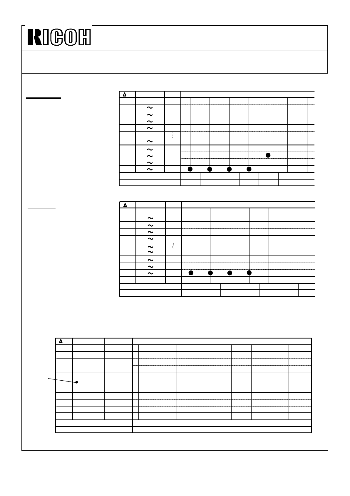
3. Step 12, TD and TGRD Data Sheet (Page 5-7)
When filling in TGRD column based upon TGRD target data (SPD515 ~ 518), be sure
to write the correct range as shown in page 5-7 of the service manual.
If not, there is a possibility of making a mistake in plotting the data due to
misunderstanding of the range. A typical mistake that we have seen is shown on the
next page. Due to the TGRD column being filled in incorrectly, ∆TD was judged as "0"
(OK). (Correct ∆TD is "--1".) As a result, cyan toner is controlled low, showing "low
cyan image density."
Page 2
Technical Bulletin No. RTB-001
SUBJECT: Additional information to TD check DATE: 15 July, ’92
PAGE: 2 of 5
[CYAN]
CORRECT
Since 4th detected TGRD
data is out of OK range,
TD data is changed from 9
to 8. Then, a 5th time.
TD
+1
OK
OK
OK
OK
OK
OK
OK
OK
-1
TD
TGRD
109 118
104 108
101 103
89 100
88
83 87
78 82
73 77
68 72
48 67
(493)
(523)
±α
+30
+20
+15
+12
-5
-10
-15
-20
-40
9
50 61 64 66
2 3 4 5 6 71TGRD
8
73
[CYAN]
WRONG
Due to the TGRD column
being incorrectly filled in,
TGRD data from 1st to 4th
checks are plotted in the
wrong locations, resulting
in no TD change.
TD
+1
OK
OK
OK
OK
OK
OK
OK
OK
-1
TD
TGRD
109 118
104 108
101 103
89 100
84 88
79 83
74 78
69 73
49 68
Upto 48
(493)
(523)
±α
+30
+20
+15
+12
-5
-10
-15
-20
-40
9
50 61 64 66
2 3 4 5 6 71TGRD
To prevent this mistake, this sheet has been changed as shown below.
This new sheet is attached to the last page of this RTB. Keep it in your service manual.
[Black]
SPD515
data
(TGRD
Target)
TD TGRD Range
+1
OK
OK
OK
OK
OK
OK
OK
OK
OK
-1
TD Data
TGRD Detected Data
± Range
+26 ~ +35
+21 ~ +25
+16 ~ +20
+11 ~ +15
+ 1 ~ +10
±0
-- 5 ~ -- 1
--10 ~ -- 6
--15 ~ --11
--20 ~ --16
--40 ~ --21
(490)
(520)
2 3 4 5 6 7 8 9 101
Page 3
Technical Bulletin No. RTB-001
SUBJECT: Additional information to TD check DATE: 15 July, ’92
PAGE: 3 of 5
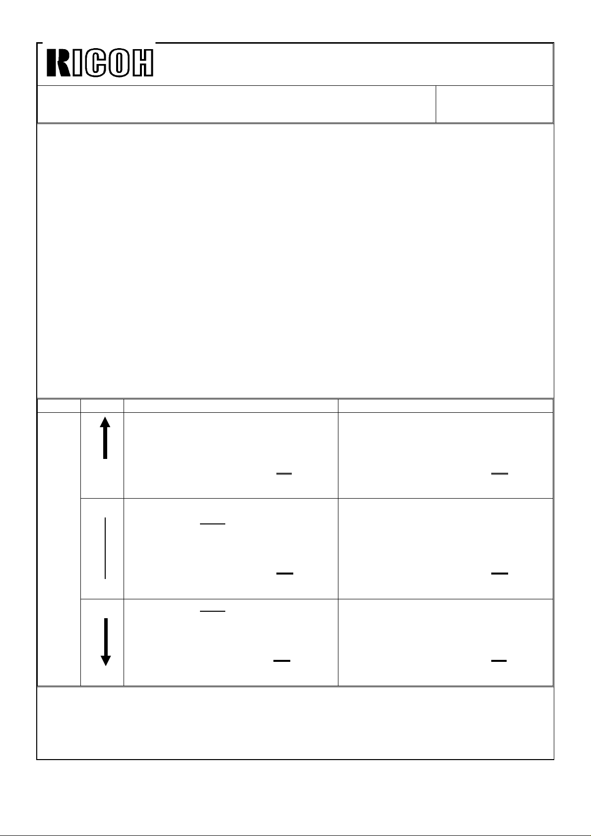
4. Step 21, image density for each color using color patch (SPD 82--H)
1) After getting TGRD detected data into "OK" area (SPD520 ~ 523), set SPD82 to "H"
to print 15 mm color patches using 7th LD power.
2) Make a test copy and check the following two points:
➀. Image density of color patches in BK, M, Y, and C. (See the one on the left side
which is 100% dots filling.)
➁. Toner scattering around those patches.
STANDARD: Compared with the standard color patch sample of the 7th LD power
enclosed in the manual, image density of each color on copy should
be equal to or higher than the standard sample, but there shouldn’t
be any toner scattering around those patches.
3) If a patch is lighter than standard, or if it is too dark with toner scattering, the next
steps should be done only for the abnormal color(s) depending upon the difference
of ±α.
±α=
[Last TGRD detected data (SPD 520 ~ 523)--TGRD target data (SPD 515 ~ 518)]
±α
Color patch is too dark. (ID is too high.) Color patch is too light. (ID is too low.)
1. ∆TD: +1 (Increase TD data by "1", using
SPD490 ~ 493.)
+16
+15
--10
--11 1. Lower TGRD target data
[(SPD520 ~ 523) - - - - (SPD515 ~ 518)]
Last TGRD detected data ---- TGRD target data
2. Repeat steps #13 through #17 two times,
and plot TGRD detected data on a new
check sheet.
1. ∆TD: +1 (SPD490 ~ 493.) 1. ∆TD: --1 (SPD490 ~ 493.)
2. Lower TGRD target data
by -15 for BK and M or
-20 for Y and C.
(SPD515 ~ 518)
3. Repeat steps #13 through #17 four times,
and plot TGRD detected data on a new
check sheet.
by -15 for BK and M or
-20 for Y and C.
(SPD515 ~ 518)
2. Repeat Step #13 through #17 four times,
and plot TGRD detected data on a new
check sheet.
1. Raise TGRD target data
by +15 for BK and M or
+20 for Y and C.
(SPD515 ~ 518)
2. Repeat steps #13 through #17 four times,
and plot TGRD detected data on a new
check sheet.
2. Raise TGRD target data
by +15 for BK and M
+20 for Y and C.
(SPD515 ~ 518)
3. Repeat steps #13 through #17 four times,
and plot TGRD detected data on a new
check sheet.
1. ∆TD: --1 (SPD490 ~ 493.)
2. Repeat steps #13 through #17 two times,
and plot TGRD detected data on a check
new sheet.
NOTE1: The TD setting can be between 0 and 30. If there are no more steps to shift,
change the ND setting by same value. (SPD495 ~ 498)
NOTE2: When TGRD target data is changed, the free run/self-check must be done
four times. (A new check sheet is required.)
Page 4
Technical Bulletin No. RTB-001
SUBJECT: Additional information to TD check DATE: 15 July, ’92
PAGE: 4 of 5
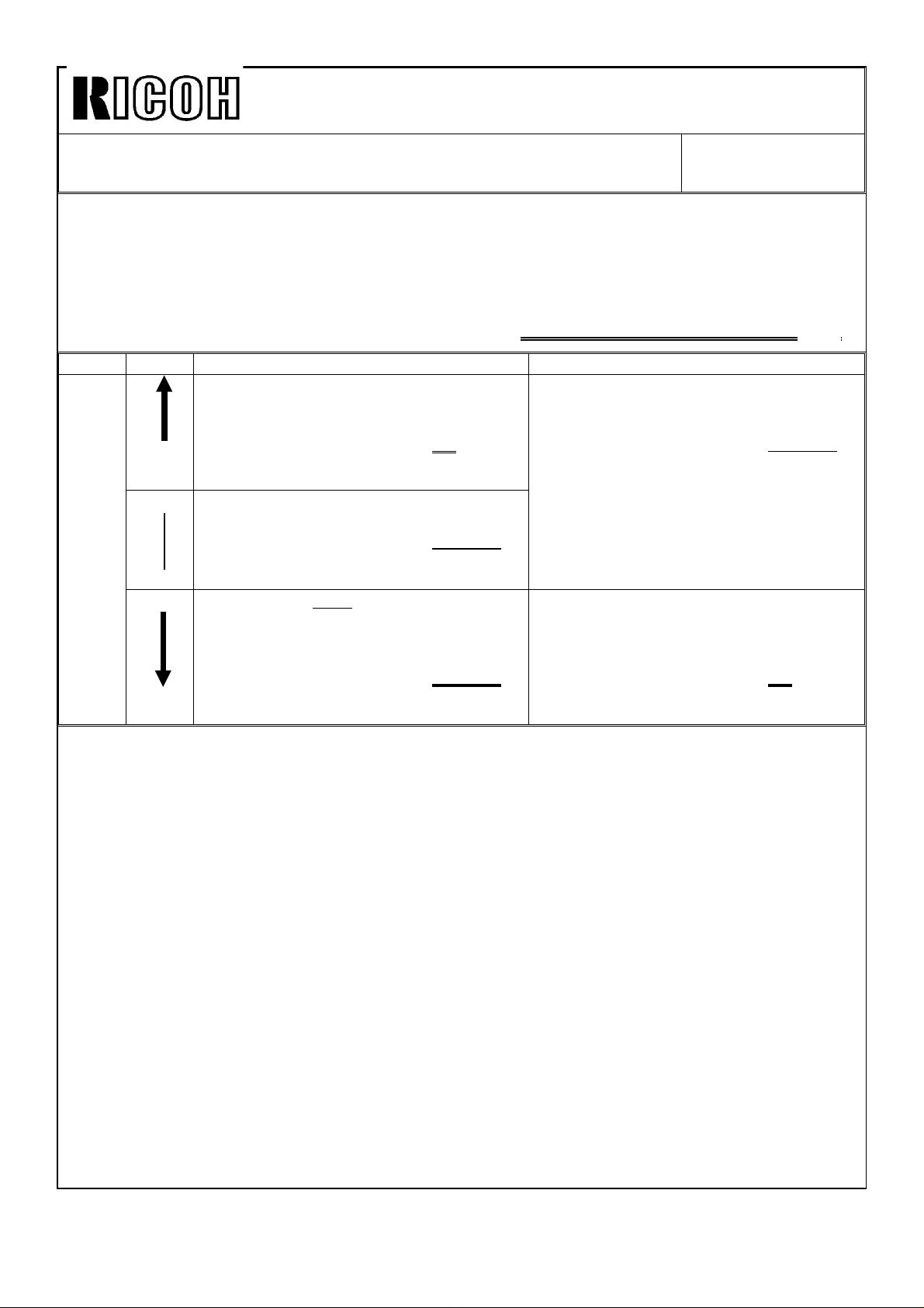
4) After repeating Step #13 through #17 two times (only when TD data is changed), or four
times (when TGRD target data is changed.), check the color patches (7th LD power) again.
If it is too light or too dark, the next steps should be done only for the abnormal color(s)
depending upon the difference of
[Last TGRD detected data (SPD520 ~ 523) -- TGRD new target data (SPD515 ~ 518)]
Color patch is too dark. (ID is too high.) Color patch is too light. (ID is too low.)
1. ∆TD: +1 (Increase TD data by "1", using
SPD490 ~ 493.)
2. Repeat steps #13 through #17 two times,
+16
+15
--10
--11 1. Lower TGRD target data
(SPD520 ~ 523) - - - - (SPD515 ~ 518)
Last TGRD detected data ---- TGRD target data
and plot TGRD detected data on a check
sheet.
1. Lower TGRD target data by --10.
(SPD515 ~ 518)
2. Repeat steps #13 through #17 four times,
and plot TGRD detected data on a check
sheet.
by -15 for BK and M,
-20 for Y and C from the present data.
(SPD515 ~ 518)
2. Repeat steps #13 through #17 four times,
and plot TGRD detected data on a new
check sheet.
1. Raise TGRD target data
by +10.
(SPD515 ~ 518)
2. Repeat steps #13 through #17 four times,
and plot TGRD detected data on a check
sheet.
1. ∆TD: --1 (SPD490 ~ 493.)
2. Repeat steps #13 through #17 two times,
and plot TGRD detected data on a check
sheet.
Page 5
Technical Bulletin No. RTB-002
SUBJECT: Exposure lamp position DATE: 15 July, ’92
PAGE: 1 of 1
PREPARED BY: I. Kakegawa
CHECKED BY:
CLASSIFICATION:
Action Required
Troubleshooting
Retrofit Information
This is additional troubleshooting information for the exposure lamp experienced in Europe.
1. Additional information to the service manual, page 5-28, #2
2. Set both lamp-heater assemblies in the scanner so that:
•
open parts face the center, and
•
two pins on the rear lamp terminal are fully inserted into the rear
New
lamp receptacle.
(There should be no gap between the rear receptacle and the
rear end of the lamp.)
Revision of service manual
Information only
Other
FROM: Copier Technical Support Section
MODEL:
PDC-1E
2. Troubleshooting
If the two pins on the rear lamp terminal are not fully inserted, the rear lamp terminal
connection may be poor. Then, the inner surface of the lamp tube turns black on the
rear side due to abnormal heat generation, resulting in low illumination on this area. In
this case, the following will be observed:
1) The exposure lamp is turned on and off during scanning, because the lamp is just
going to be open circuit.
2) Color tone on the rear side of the copy image is not the same as at other areas
because of the dark lamp area. Under this condition, replace the exposure lamps.
Page 6
Technical Bulletin No. RTB-003
SUBJECT: Key counter mode copy DATE: 15 July, ’92
PAGE: 1 of 1
PREPARED BY: I. Kakegawa
FROM: Copier Technical Support Section
CHECKED BY:
CLASSIFICATION:
Action Required
Troubleshooting
Retrofit Information
Revision of service manual
Information only
Other
MODEL:
PDC-1E
To enable copy operation with the key counter, do the following:
1. Install the key counter receptacle.
2. Turn off SW100 on the sequence control board (rear side) to select key counter mode.
3. Then, depending upon the customer’s request for key counter management, input the
appropriate data (from 0 to 7) in SPD12. (See page 4-24)
This is to decide in which color modes the key counter is incremented.
Data Full Color Single Color Black
0 0 0 x x x
0 0 1 o x x
0 0 2 x o x
0 0 3 o o x
0 0 4 x x o
0 0 5 o x o
0 0 6 x o o
0 0 7 o o o
o: Count up
x: No count up
[Example] SPD12-001: The key counter shows the number of full color copies made.
SPD12-007: The key counter shows the total number of copies made in
all three color modes.
NOTE: When key counter mode is selected by turning off SW100 on the sequence
control board, the key counter should be set for any copy operation
regardless of SPD12 data.
[Manual correction on page 4-24, SPD12]
o: Key counter required o: Count up
x: No key counter required x: No count up
Default: 0 0 7 Default: 0 0 0
Page 7
Technical Bulletin No. RTB-004
SUBJECT: Forced self check operation with new ROMs DATE: 15 July, ’92
PAGE: 1 of 3
PREPARED BY: I. Kakegawa
CHECKED BY:
CLASSIFICATION:
Action Required
Troubleshooting
Retrofit Information
1. SPD-22, Forced self check operation
In order to perform the self check operation at a certain copy interval, the following two
ROMs has been changed to "C" version.
P/N A0925507B C (ROM on the sequence control board)
P/N A0925509B C (ROM on the process board)
This modification will be applied from July,’92 production onward. By replacing old ROMs
with these two new ROMs as a set, SPD-22 can be accessed.
SPD-22: Forced self check operation at a certain copy interval
0: No self check operation (Default)
Revision of service manual
Information only
Other
FROM: Copier Technical Support Section
MODEL:
PDC-1E
1: Yes, at every 200 copies
2: Yes, at every 400 copies
3: Yes, at every 600 copies
4: Yes, at every 800 copies
5: Yes, at every 1,000 copies
The default setting of SPD-22 is "0". If a data from 1 to 5 is selected, self check operation
automatically starts just after the last copy of that copy job is fed out when the total copies
made since the last self check becomes more than the set copy number.
The self check at around noon, set by SPD-21, is performed independently, regardless of
the number of copies made since the last check.
Page 8
Technical Bulletin No. RTB-004
SUBJECT: Forced self check operation with new ROMs DATE: 15 July, ’92
PAGE: 2 of 3
By both morning and noon self checks, the copy counter for the next self check is reset to
"0". However, it is not reset by just turning off and on the main switch.
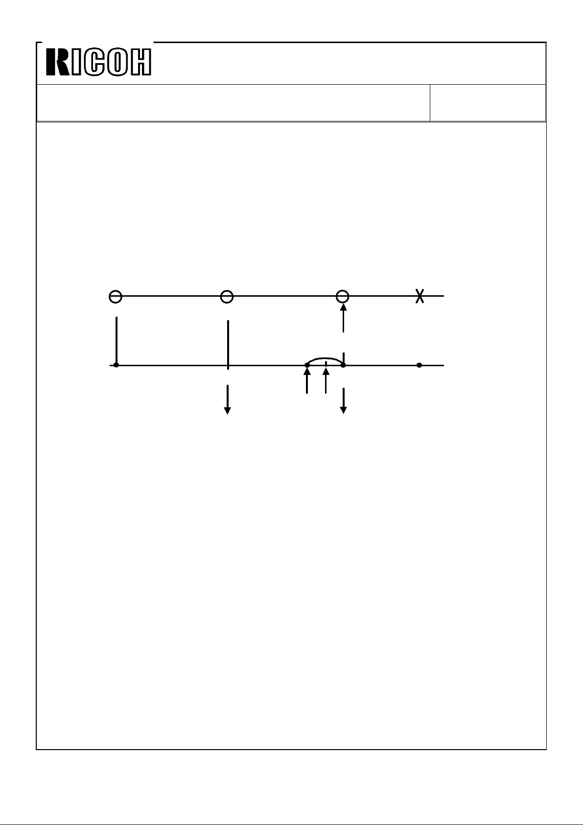
[EXAMPLE] Conditions 1. SPD20-L: Noon self check on.
2. SPD21-120: 90 + 120 = 210 minutes, Noon check is
done 3.5 hours after the main switch is turned on.
3. SPD22-2: Self check at every 400 copies.
4. In the morning, 210 copies are made.
5. In the afternoon, 560 copies are made.
Turn on/Self check Self check Self check
9:00 12:30
1 job: 70 copies
Counter
Reset to 0
210 copies
381
0 0
(Start)
450 (Finish)
400
Turn off
110 copies
2. Purpose
Under the following conditions, there is a possibility of a toner concentration problem,
especially for magenta color.
1) Since the last self check, 800 to 1000 copies or more have been made.
2) The number of copies from one original (C/O), is rather high.
3) Low humidity.
If these conditions are met, magenta toner concentration becomes high. Then, by VSG
detection, greater pointer data and ND data will be selected, lowering toner
concentration. Due to long copy runs without self check, toner control target (VTC) can
not be revised by TGRD detected data (ND and CD data). Then, low image density for
high tone areas may happen due to too low toner concentration. Due to high C/O, DIF
detection is not performed for long copy runs, resulting in no pointer shift even if
humidity condition have been changing. Because of this, toner concentration becomes
too high or too low against the latest humidity condition.
To avoid the toner concentration problem, perform the following action.
Page 9

Technical Bulletin No. RTB-004
SUBJECT: Forced self check operation with new ROMs DATE: 15 July, ’92
PAGE: 3 of 3
3. Action Taken
1) For machines from the July,’92 production with "C" version ROMs on both the
sequence control board (P/N A0925507C) and the process control board (P/N
A0925509C)
Set data "2" (400 copies) or "3" (600 copies) of SPD-22.
Then, explain the self check operation at set copy intervals to customers, and ask them to wait for one or two
minutes.
2) For machines upto the June,’92 with upto "B" version ROMs.
a) Manual self check
Set SPD30-H to perform a self check
whenever the main switch is turned on. Ask
the customer to turn off and on the main
switch at every 400 to 600 copies or at any
time the image density becomes too low or too
high.
b) Automatic self check by new ROMs
If it is difficult for the customer to turn off and on
the switch regularly, install the new ROMs as a
set, and set SPD22 to 2 or 3.
NOTE: These two ROMs are 512 K.
Page 10
Technical Bulletin No. RTB-005
SUBJECT: Important parts to be cleared regularly DATE: 15 July, ’92
PAGE: 1 of 1
PREPARED BY: I. Kakegawa
CHECKED BY:
CLASSIFICATION:
Action Required
Troubleshooting
Retrofit Information
As explained in the PM table in the service manual (page 4-1 ~ 4-3), there are parts to be
cleaned at every EM. Among these parts, the most important parts are as follows;
1. Grid plate
If the grid plate becomes dirty, the copy image is not even, especially for low to middle
solid areas on originals. Then, vertical dark stripes are copied on such a solid area.
This is caused by a dirty grid plate. To prevent this, clean the grid plates at every EM visit.
Put them in water, wash them, and dry them.
NOTE: Do not fold them while washing.
Be sure that there is no fiber dust remaining on them.
Revision of service manual
Information only
Other
FROM: Copier Technical Support Section
MODEL:
PDC-1E
2. Optical fiber array
If you have the impression that the copy image is less sharp or less crisp than at
installation, try to clean the optical fiber array with a soft cloth. (Black stains will be
removed.)
Clean the array at every EM with a soft cloth, and then discharge it by wiping with your
clean finger.
Page 11
Technical Bulletin No. RTB-006
SUBJECT: VLL/VLH pattern on the reverse side of copy DATE: 15 July,’92
PAGE: 1 of 1
PREPARED BY: I. Kakegawa
CHECKED BY:
CLASSIFICATION:
Action Required
Troubleshooting
Retrofit Information
If VLL/VLH line pattern (10 mm x 10 mm, see page 2-17 of manual) is visible on the reverse
side of copy paper, set SPD-11-H.
These line patterns used for DIF detection are developed just after the last copy of that
copy job has been made. Then, they are checked by the ID sensor, and are transferred
on the transport belt. Normally, the belt stops turning just before the patterns on the belt
are cleaned. At the next copy job, they are cleaned.
However, if the machine is used less frequently due to low copy number, or is used under
high temperature conditions, these pattern made at last copy job may not be cleaned
completely. Then, they are put on the reverse side of the next copy paper.
SPD11 is to control belt cleaning time at the end of copy job.
If SPD11 data is changed to "H", the belt turns 2 seconds longer than usual to clean the
pattern before the belt stops.
Revision of service manual
Information only
Other
FROM: Copier Technical Support Section
MODEL:
PDC-1E
NOTE: For the machines with low copy volume used under high temperature conditions,
set SP11 to "H". In this case, it takes 2 seconds longer for the machine to be
back to "Ready" condition.
Page 12
Technical Bulletin No. RTB-007
SUBJECT: Parameter setting for AC Power Pack (Discharge) DATE: July 15,1992
PAGE: 1 of 1
PREPARED BY: T. Okajima
CHECKED BY:
CLASSIFICATION:
Action Required
Troubleshooting
Retrofit Information
1. Summary
The service manual describes that the data of SPD430 is "800" and SPD431 is "300"
(SPD430: Transfer belt discharge voltage, SPD431: Separation corona voltage).
However, these SPD’s were adjusted at the factory to other parameters for stabilizing
the output voltage of the power packs. So, to fix the parameter of these SPD, the power
packs have been modified.
AC Power Pack - Discharge : AZ310013 → AZ310013A → AZ310014
Two AC Discharge Power Packs are used in one machine. These parts are identical,
one is used for the transfer belt discharge, and the other is used for the separation
corona. When you replace the power pack with a new one, or when the parameter of
SPD430 or SPD431 is erased for some reason and some problems occur, refer to the
following section:
Revision of service manual
Information only
Other
FROM: Copier Technical Support Section
MODEL: PDC-1E
2. Details
1) Possible problem
If the following parameter is bigger than the specified one;
SPD430 (Transfer belt discharge) - no problem but waste of power,
SPD431 (Separation corona voltage) - void image, toner scattering on the copy,
If the following parameter is lower than the specified one;
SPD430 - remained image, poor transfer of Bk image,
SPD431 - poor paper separation,
2) Parameter setting
If the problem above occurs, check the parameters of SPD430 and SPD431 refering to
the table.
According to our records, P/N AZ310013 and P/N AZ310013A do not exist as service
parts. When you replace the power pack with a new one (P/N AZ310014), set the
parameter for SPD430 at 780, and the parameter for SPD431 at 280 for any machine.
Note: If you have a P/N AZ310013(A), please inform us. We will send you the P/N
AZ310014 instead.
Serial number AC Power Pack A092 - 22 092 - 27 Discharge SPD 430 SPD 431
First production
~
No production A3012030001 ~ P/N AZ310013A 570 135
4302040001 ~ A3012030011 ~ P/N AZ310013A 570 050
4362040006 ~ A3012050001 ~ P/N AZ310014 780 280
First production ~ P/N AZ310013 800 300
Page 13

Technical Bulletin No. RTB-008
SUBJECT: Discolored spots on color background DATE:Sep. 15, ’92
PAGE:1 of 2
PREPARED BY: T. Okajima
CHECKED BY:
CLASSIFICATION:
Action Required
Troubleshooting
Retrofit Information
To prevent discolored spots due to the carrier, install the following two ROM’s as a set:
• One new ROM on the sequence control board (512K): P/N A0925507D (Check sum:
E1E8)
• One new ROM on the process control board (256K): P/N A0925509C (Check sum:
DF8F)
Revision of service manual
Information only
Other
[Symptom]
• After the self check operation both in the morning and
around noon, discolored spots are obsorbed at the
leading and the trailing parts of the copy image for
about initial ten copies. After making ten copies, these
spots will gradually disappear.
FROM: Copier Technical Support Section
MODEL: PDC-1E
• When you touch these spots on the copy with your
fingers, you can feel the carrier. Due to carrier
particles, toner around the carrier particle can not be
transferred from the OPC drum to the copy paper,
resulting in discolored spots.
±5 mm
carrier
±10 mm
[Cause]
Due to a software error of the sequence control ROM, the "OFF" timing of development
bias was a little early compared to that of drum charge during the self check run. This
causes carrier to drop from the development unit onto the mylar of the cleaning unit.
Since this mylar moves up and down while paper is passing through the image transfer
section, the carrier on the mylar will drop on the initial ten copies from the mylar.
This symptom will be worse when the pointer data (SPD110~113) is over 20. Because the
drum charge becomes so high that a greater amount of carrier will be dropped.
Page 14

Technical Bulletin No. RTB-008
SUBJECT: Discolored spots on color background DATE:Sep. 15, ’92
PAGE:2 of 2
[Action taken]
1. Clean the carrier dropped from the development units onto:
• The bracket located just under the black development unit.
• The mylar on the black, magenta, and yellow cleaning units.
• The black plastic parts located just under the rear half of each development unit.
2. Clean each cleaning unit.
3. Replace two ROM’s with the following new ones on both the sequence control board
and the process control board.
1) One new sequence control ROM (512K): P/N A0925507D (Check sum: E1E8)
2) One new process control ROM (256K): P/N A0925509C (Check sum: DF8F)
• For the July ’92 production and some of the June ’92 production, A0925509C has been
installed at the factory. (see below.) For these machines, install only A0925507D.
• Using the above ROM’s, SPD22 (forced self check operation at a certain copy interval)
can be operational as explained in RTB-004.
• P/N A0925509C was explained as 512K by mistake in RTB-004.
It was 256K.
[Cut-in serial number]
The above action is required for all machines up to the July ’92 production.
ROM’s Purpose
A0925507C
and
A0925509C
A0925507D
and
A0925509C
To enable SPD22
(explained by
RTB-004).
To prevent
discolored spots
(explained by this
RTB).
Ricoh
A092-17
No production.
From the first
production in
August ’92.
Gestetner
A092-22
Two June ’92
production
[#4302060001]
[#4302060002]
All July
production
[#4302070001~]
onward.
From August ’92
production.
Ricoh
A092-27
Four June
production
machines.
[#A3012060001
[#A3012060008
[#A3012060011
[#A3012060012
All July
production
[#A3012060001~]
onward.
From August ’92
production.
Page 15

I{numl
Technical Bulletin
No. RTB-009
SUBJECT: EPROM Software History
PREPARED BY: T.
CHECKED
CLASSIFICATlOl(
BYL~--+-~~
❑ Action Required
❑ Troubleshooting
❑ Retrofit Information
Okajima/
-
❑ Revision of service manual
■ information only
❑ Other
%
/
FROM: Copier Technical Support Section
MODEL: PDC-I E
DATE: Aug. 31, ’93
PAGE:
1. Summary
This bulletin describes the EPROM history of the PDC-1E model.
In total, 13 ROMs are used for one machine. When the software is modified, combinations
i
of the modified ROMs will be changed as required. Since these modifications can be very
complicated, we made the ROM modification chart appended to this RTB. In this chart,
you will find symbols like
match the explanations below.
“d)”.
This is the modification reference number. These numbers
2. Modification Contents
1 of 8
(D
Abnormal copy image
Problem
When pressing the clear stop key while pre-scanning, an abnormal copy may be printed
out.
Cause
Software error
Solution
Correct the software of
board, and the process
Operation Panel Board:
Sequence Control Board A0925507
Process Control Board
Cut-in serial number
the EPROMs on the operation panel board, the sequence control
control board.
A0925517
A0925518
A0925513
A0925514
A0925509
+
A
+
A
+
A
+
A
+
A
+
A
The new EPROMs have been used from the January 1992 production run.
Page 16

lmxml
Technical Bulletin
No.
RTB-009
SUBJECT: EPROM Software History
Q
Problems in the editor mode and the slide projection mode
Editor mode
Problems
The white key cannot be used.
When selecting one of the original types (Letter, Photo,
sometimes selected by error.
When entering the editor mode just after turning on the
cannot be used.
Cause
f
Software error
Solution
Correct the software errors of the EPROMs on the operation panel board.
Letter/Photo), another type is
main switch, the mode clear key
DATE: Aug. 31, ’93
PAGE: 2 of 8
Slide projector mode
Problem
When selecting the photo mode, the Photo/Letter mode is sometimes selected instead.
In auto magnification mode, an unsuitable magnification ratio is selected.
Key is locked.
Cause
Software error
Solution
Correct the software of the EPROMs on the operation panel board.
Operation Panel Board
A0925515
A0925516
A0925517A
A0925518A
A0925513A
A0925514A
+
+
-+
+
-+
+
A
A
B
B
B
B
Cut-in serial number
New EPROMs have been used from the March 1992 production run.
I
Page 17

KU(NMI
Technical Bulletin
No. RTB-009
SUBJECT: EPROM Software History
@
Parameter settings for SPD430 (Transfer belt discharge voltage) and
DATE: Aug. 31, ’93
PAGE: 3 of 8
SPD431 (Separation corona voltage)
Problem
The output voltages of the transfer belt discharge and the separation corona voltage are
controlled by the parameters of SPD430 and SPD431. Direct voltages are used for the
parameters on the old ROMs. However, when the power pack lot was changed, these
parameters had to be changed at the factory. See
Solution
To standardize the parameters of SPD430 and
changed from a direct voltage parameter to a duty parameter. The duty parameter can
control the output voltage of the power packs with more accuracy. Also, the power packs
have been modified to match the duty control. The part number of the
been changed from #AZ310013 to #AZ310014. Several combinations of power pack and
the ROM version exist in the field and the parameter is different for each combination.
Keep the parameter as shown in the table below.
RTB-007.
SPD431,
the control method has been
power pack has
Cut-in Serial
Number
AC Power Pack
Process Control ROM
(A0925509A)
Process Control ROM
(A0925509B)
Process Control ROM
(A0925509C)
*1: There are 2 types of the AC Power Pack for part no. AZ310013A (Type 1 and Type 2).
The characteristics of each type changed because each was manufactured in a different
lot. This resulted in a change of output of the separation corona voltage
NOTE:
As there is only the AC Power Pack (#AZ310014) in the field as a service part, set the
parameters SPD430 to 780 and
RICOH
NRG
First
production-
First production-
AZ310013
SPD430: 800
SPD431
SPD430: 700
SPD431
:300
:200
SPD431
A3012030001- A3012030011-
No production
AZ310013A AZ310013A
(Type
This combination does not exist in the field.
SPD430: 570
SPD431
to 280 when the AC power pack is replaced.
1)*1
:135
4302040001-
(Type
SPD430:
SPD431
2)*1
570
:050
A30120500014302040006 -
AZ310014
SPD430:
SPD431
(SPD431
780
:280
).
Page 18

Technical Bulletin
No.
RTB-009
SUBJECT: EPROM Software History
@
SP mode problem
Problem
● When entering ON in SP62 (Copy Modes Counter Clear), the SPU counter is not cleared.
. The default of SP33 (Auto Cassette Shift) is set to ON by error. This should be OFF.
Cause
Software error
Solution
Correct the software as follows:
System Control Board:
Cut-in Serial Number
SPU counter is cleared bv
The default of SP33 is set to OFF.
A0925525A + B
A0925526A + B
SP62.
DATE: Aug. 31, ’93
PAGE: 4 of 8
The New EPROMs have
@
Forced self check operation
This modification is described in RTB-004 (PDC-1E). To stabilize the toner concentration
for high copy volume customers, two self-checks a day are not enough, especially for
magenta color. So, we added a self-check for a certain copy interval.
SPD-22 : Forced self-check operation
0 : No (Default)
I
1: Yes, at every
2: Yes, at every
3: Yes, at every
4: Yes, at every
5: Yes, at every
Sequence Control Board:
Process Control Board:
Cut-in Serial Number
Self-check is performed only depending on SPD-20,
SPD-30.
been used from the May 1992 production run.
(SPD-22)
200 copies
400 copies
600 copies
800 copies
1000
copies
A0925507B
A0925509B
+
C
+
C
SPD21,
and
The New EPROMs have been used from the July 1992 production run.
Page 19

Technical Bulletin
No.
RTB-009
SUBJECT: EPROM Software History
@
Discolored spots on color background
This modification is described in RTB-008 (PDC-1E).
Problem
After the self-check operation both in the morning and around noon, discolored spots are
observed at the leading and the trailing parts of the copy image for about the first ten
copies. After making ten copies, these spots will gradually disappear. These spots are
made by carrier.
Cause
Software error. See
Solution
Correct the software as follows:
Sequence Control Board
RTB-008.
A0925507B
+
C
DATE: Aug. 31, ’93
PAGE: 5 of 8
Cut-in Serial Number
The New EPROMs have
@
Three language messages (Swedish, Norwegian, Danish) added on the
been used from the July 1992 production run.
220-240V version model
Select one of the setting in the table below to display the language you want
II
A4 version
II
I
Swedish 0110
Norwegian 1110
Danish
The EPROMs on the operation panel board have been modified as follows:
Operation Panel Board A0925515A
A0925516A
A0925517B
A0925518B
A0925513B
A0925514B
0001
+
B
+
B
+
C
+
C
+
C
+
C
Cut-in Serial Number
The New EPROMs have been used from the August 1992 production run.
Page 20

l{OGOM
Technical Bulletin
No.
RTB=O09
SUBJECT: EPROM Software History
@
A3 double count problem
Problem
A3 double count mode can be set by
is incremented by two. However, if the main switch is turned off and on, the setting of
SP45 is returned to off, so that even if another A3 copy is made, the total counter is
incremented by only one.
Cause
Software error
Solution
Correct the software of the EPROMs on the operation panel board and the sequence
control board as follows:
Operation PaneI B.: A0925515B
A0925516B
A0925517C
A0925518C
A0925513C
A0925514C
SP45.
+
D
+
D
+
E
+
E
+
E
+
E
When an A3 copy is made, the total counter
Sequence Control B.: A0925507D
Process Control B.:
DATE: Aug. 31, ’93
PAGE: 6 of 8
A0925509C + D
+
E
Suffix C (A0925515 and A0925516) and suffix D (A0925517, A0925518, A0925513, and
A0925514) are not used on the production run.
Cut-in Serial Number
New EPROMs have been used on the production run from November 1992 and the
following machines:
A092-27: September production:
(10 units)
October production:
(10 units)
A092-22: October production:
A092-17: September production:
For the field machines, we sent the replacement EPROMs to you.
A301209-0013, 0014, 0016, 0020, 0021, 0022, 0023,
-0024, 0036, 0030
A301210-0022, 0023, 0024, 0025, 0026, 0028, 0030
-0031, 0033, 0034
430210-0015 to 0023, (9 units)
All
Page 21

Ku(Mml
Technical Bulletin
No.
RTB-009
SUBJECT: EPROM Software History
(2
Service logging data printed wrong position
Problem
Service logging data is printed at the wrong position on the copy paper. All data is shifted
to one side.
Cause
Software
Solution
Correct the software of the EPROMs on the system
System Control Board
Cut-in Serial Number
error
A0925525B
A0925526B
A0925527A
A0925528A
control board.
+C
+C
+B
+B
DATE: Aug. 31, ’93
PAGE: 7 of 8
New EPROMs have been used from the November
@
Abnormal Copy Image on SPU or Editor
Problem
When selecting the designated area with the editor board and using the centering mode,
the imaae is not
When using the image repeating
on the copy.
(
Cause
Software
Solution
The software in
System Control
error
exactlv
the EPROMs
Board
centered.
mode with the slide projector, a smeared image appears
on the system control board has been corrected.
A0925525C
A0925526C
A0925527B
A0925528B
+D
+D
+C
+C
1992 production run.
mode
Cut-in Serial Number
The new EPROMs have been
used
from February 1993 production run.
Page 22

I{ll(mxl
Technical Bulletin
No.
RTB-009
SUBJECT: EPROM Software History
3.
Latest Version EPROMs, as of August 1993
PCB
Sequence Control B.
Process Control B.
Operation Panel B.
(Common)
Operation Panel B.
(mm) .
Operation Panel B.
(inch)
System Control B.
IC
No.
134
238 A0925509
133
134
135
136
131
132
131
132
130
126
129
125
124
Part No.
A0925507
A0925515
A0925516
A0925517
A0925518
A0925513
A0925514
A0925543
A0925544
A0925525
A0925526
A0925527
A0925528
A0495504
Latest Check
Suffix
E
D
D
D
E
++
E
R--R-i
c
c
H%--15’2K
El&L
Bits
-sum
E664 512K
E5F7 256K
EA55 1M
286A
687C
E494
IA41
E
I
I
E449
I
DATE: Aug. 31, ’93
PAGE: 8 of 8
Recommended EPROM
Type
AMD:AM27C512-155DC
Fuiitsu:MBM27C512-20
lntel:D27256
AMD:AM27C256-155DC
AMD:AM27C256-205DC
Hitachi:
lntel:D27C010-150V10
AMD:AM27C010-155DC
Fujitsu: MBM27C1001-15
lnteI:D27512J-2
AMD:AM27C51 2-155DC
Fujitsu: MBM27C512-20
HN27C256G-25
Page 23

●
1: Suffix C was not applied on the production run.
●
2: Suffix D was not applied on the production run.
@:
Production run start.
@-@
Modification reference number. See the modification contents by referring to these numbers.
Page 24

Technical Bulletin No. RTB-010
SUBJECT: Blurred copy problem on editor board DATE: Dec.31,’93
PAGE: 1 of 3
PREPARED BY: T. Okajima
CHECKED BY:
CLASSIFICATION:
Action Required
Trouble shooting
Retrofit Information
Revision of service manual
Information only
Other
FROM: Technical Support Group
MODEL:
PDC-1E (Editor Board)
1. Problem
When making copies with th e PDC-1E using the editor board, blurred images might appear
on copies.
2. Cause
This problem occurs due to the deformed pressure pads (mirror surface). The d eformed
pad cannot press an original completely and there is a gap betwee n the original and the
exposure glass. The focal depth of the scanner is only 0.25mm. If t his gap is 0.25mm or
wider, an image in that part will be blurred.
The present pressure pad is made of polypropylen, which starts to deform from about
79°C (174.2°F) or higher. We suppose th at the editor board suffers temperatures of 79°C
or higher during transportation.
The pressure pad of the platen cover for the PDC-1E is the same as that of th e editor
board. However, the pressure pad of the platen cover does not have the deformation
problem because during transportation, the pressure pad is on the exposure glass which is
flat. Even under high temperature (higher than 79°C) it will not be deformed by the
exposure glass.
3. Countermeasure
3-1. Material
We have changed the material of the pressure pad from polypropylen to p olycarbonate
which does not deform at temperatures under 130°C (266°F).
3-2. Part number for the new pre ssure pad
Old Part Number New Part Number Description
A0491576 A0921594
This part number will be available as a
service part in February 1994.
Original Pressure Pad
Page 25

Technical Bulletin No. RTB-010
SUBJECT: Blurred Copy Problem on Editor Board DATE: Dec.31,’93
PAGE: 2 of 3
3-3. Modification procedure for the field machine
[A]
[B]
W
W
W
W: 1 mm (0.04 inch)
1. Remove the pressure pad [A] from the editor b oard.
NOTE: As some adhesive tape or sponge might remain on the editor board, make sure
to check and remove everything.
2. Put the new pressure pad [B] as shown in the illustration.
Make a 1mm (0.04 inch) space between the front scale an d the front edge of the
pressure pad, and between the right scale and the right side of the pressure pad.
3. Peel off the cover from the two adhesive tapes, close the editor board and press the
editor board by hand. Especially, press the part directly above the tapes.
4. Confirm that there is no blurred image on the copy.
Page 26

Technical Bulletin No. RTB-010
SUBJECT: Blurred Copy Problem on Editor Board DATE: Dec.31,’93
PAGE: 3 of 3
3-4. Cut-in Serial Number
Machine Code Cut-in Serial Number
A988-17 From Oct. 1993 production run (#A3223100001–)
and #A3223080001, 06, 19, 20, #A3223090001, 03
A988-25 From Oct. 19 93 produc tion run (# 429310 0001–)
A988-27 From Oct. 1993 production run (#A3223100001–)
and #A3223070047, 50, 51, 52
4. Others
We do not recommend that you modify the editor board when it is not on the copier, it is
very difficult to adjust the position for setting the pressure pad. You might have matching
problems when the editor b oard is docked to the copier (e.g.. the pressure pad falls on the
scale or the space between the edge of the pressure pad and the scale is much larger).
Page 27

Technical Bulletin No. RTB-011
SUBJECT: 1st and 2nd synchronizing mirrors installation procedure DATE: Aug. 31, ’94
PAGE: 1 of 3
PREPARED BY: S. Orita
CHECKED BY:
CLASSIFICATION:
Action Required
Troubleshooting
Retrofit Information
During transportation, one or more of the 1st and 2nd synchronizing mirrors for black,
magenta, yellow, and cyan sometimes dislodges from the laser unit frame due to
insufficient adhesive.
As a result, the following service codes are displayed:
For black ……… SC640 and SC710
For magent a ……… SC640 and SC711
For yellow ……… SC640 and SC712
For cyan ……… SC640 and SC713
Previously, this could be corrected only by replacing the laser unit assembly, which is quite
expensive.
To reduce the service cost a nd meet the field requests, the 1st and 2nd synchronizing
mirrors have been registered as service parts as follows:
Revision of service manual
Information only
Other
FROM: 2nd Technical Support Section
MODEL:
PDC-1E
1st synchronizing mirror (for black, magenta, cyan and yellow) ……P/N A0492128
2nd synchronizing mirror (for black, magenta, cyan and yellow)……P/N A0492130
The installation proced ure for the 1st and 2nd synchronizing mirrors are as follows:
[C]
1. Remove the laser unit from the copier
(See the service manual pages 5-39 and
5-40.)
2. Place the laser unit [A] on a flat table.
3. Remove the fiber optics cables [B] from the
clamps.
4. Remove the upper cover [C] with LD control
board [D] of the laser unit.
(6 screws and 5 connectors)
[B]
[D]
[A]
Page 28

Technical Bulletin No. RTB-011
2nd magenta mirror
1st yellow
mirror
1st
cyan
mirror
[E]
SUBJECT: 1st and 2nd synchronizing mirrors installation procedure DATE: Aug. 31, ’94
PAGE: 2 of 3
5. Reverse the laser unit and carefully place it on
the table.
6. Remove the bottom cover [E] of the laser unit
(6 screws).
[F]
7. Confirm the location of each synchronizing mirror
and confirm which mirror should be removed.
8. Remove the fiber cable bracket [F]
corresponding to the position of the
mirror to be removed. (3 screws)
Bottom
1st black mirror
1st magenta
Upper
2nd cyan mirror
2nd
black
2nd yellow
mirror
Page 29

Technical Bulletin No. RTB-011
SUBJECT: 1st and 2nd synchronizing mirrors installation procedure DATE: Aug. 31, ’94
PAGE: 3 of 3
- 1st synchronizing mirror [G] -
9. Remove the 1st synchronizing
mirror. (1 screw)
10. Reassemble the machine.
- 2nd synchronizing mirror [H] -
9. Before removing the 2nd
synchronizing mirror, mark the
groove position [I] of the adjusting
cam [J].
10. Remove the 2nd synchronizing mirror.
(1 short screw [K], 2 washers [L],
1 long screw [M], and adjusting cam [J] )
11. When installing the 2nd synchronizing
mirror, at first, fix the mirror by th e short
screw and washers while holding the
mirror. Then, install the long screw and
adjusting cam.
Note: Make sure that the groove [I] of the adjusting cam matches the mark made in
step 9, and the dot [N] on the cam is on the opposite side from the short screw
hole [O].
[L]
[K]
[M]
[O]
[J]
[I]
[G]
[H]
[N]
12. Reassemble the machine.
13. Check the copy quality. If an SC code is displayed or a synchronizing problem occurs,
adjust the mirror position by turning the adjusting cam [J].
Page 30

Technical Bulletin No. RTB-012
SUBJECT: Hot Roller and Pressure Roller Chan ges DATE: Nov. 15, ’94
PAGE: 1 of 10
PREPARED BY: S. Orita
CHECKED BY:
CLASSIFICATION:
Action Required
Troubleshooting
Retrofit Information
To increase the expected life time of the hot roller, we have had a new hot roller and pressure
roller installed since the first product ion of the PDC-1 0E.
The PDC-1E is no longer produced, so, the se new hot roller an d pre ssure roller are available
as service parts.
Detailed information for these changes is as follo ws:
Old P/N New P/N Description Modified Point
AE010005 AE010008 Hot Roller The hardness of the rubb er ha s bee n
AE020018 AE020043 Pressure Roller The hardness of the rubber has been
Revision of service manual
Information only
Other
FROM: 2nd Technical S upport Section
MODEL:
PDC-1E
decreased.
The diameter has bee n changed from
44.7 mm to 44.5 mm.
increased.
When replacing the hot roller and/or pressure rolle r, th e followin g pro ced ure is required.
NOTE: We recommend replacing the hot roller and pressure roller at the same time in orde r t o
increase the expect ed life time of the hot roller.
Page 31

Technical Bulletin No. RTB-012
SUBJECT: Hot Roller and Pressure Roller Chan ges DATE: Nov. 15, ’94
PAGE: 2 of 10
Fusing Unit Adjustment Flow Chart
When replacing the
hot roller or pressure
roller separately.
When replacing the
hot roller and
pressure roller at the
same time.
Start from "Procedure 1"
Procedure 1
Fusing Pressure Adjustment Using Nip
Band Width
Procedure 2
Fusing Pressure Fine Adjustment by
Forcing "Mimizu" on Copy Image
Start from "Procedure 3"
Procedure 3
Fusing Unit Positioning Ad just men t by
Forcing "Mimizu" on Copy Image
Could you
finish "Procedure 3"
completely?
Procedure 4
Main Motor Speed Adjustmen t
Yes
No
Go back to
"Procedure
2"
Page 32

Technical Bulletin No. RTB-012
SUBJECT: Hot Roller and Pressure Roller Chan ges DATE: Nov. 15, ’94
PAGE: 3 of 10
1. Procedure 1
Fusing Pressure Adjustment Using Nip Band Width
Adjustment Standard:
• 7.6 ± 0.4 mm (center of nip band width; L)
• Less than 0.2 mm (d ifference between a and b)
a
L
[B]
[A]
b
1. Prepare Folex OHP she et Typ e 100.
2. Place a white paper (A3/11" x 17") on the exp osure grass and perform free run (SP1) for
3 minutes.
3. As soon as the print key be come s green, pull out the transfer belt unit and open the
fusing exit cover.
4. Insert an OHP shee t into the center of the fusing unit by turning the fusing knob manually
and wait 15 seconds to make the nip ba nd on th e OHP sheet.
5. Turn the fusing rolle r 90 degrees and then wait for 15 seconds. Repeat this step two
more times and exit the OHP sheet. You sho uld now have fo ur nip ban ds on the OHP
sheet.
6. Measure the width L, a, and b. Ave rag e ea ch pa rame ter and confirm that they are within
specification. If th ey are not , go to ste p 7. If OK, this adju stme nt is finished.
7. Remove the slotted-screws [A] (at both side) an d adjust the fusing pressure by turn ing
nuts [B].
• Turning the nut clockwise to reduce the fusin g pre ssure
• Turning the nut counterclockwise to increase the fusing pressure
Page 33

Technical Bulletin No. RTB-012
Fig. 1
–0.4
–0.6
–0.8
–1.0
SUBJECT: Hot Roller and Pressure Roller Chan ges DATE: Nov. 15, ’94
PAGE: 4 of 10
2. Procedure 2
Fusing Pressure Fine Adjustment by Forcing "Mimizu " on Copy Ima ge
1. Loosen the screws [A]
2. Turn the adjustment cam [B] which po int s to th e scale (±0) on the bracket [C] as shown
in figure 1.
±0
[B]
–0.2
[A]
(–)
±0
[A]
(+)
+0.6
+0.8
+1.0
[C]
+0.4
+0.2
±0
3. Force "Mimizu" on the copy image as follows:
• Set SPD#51 to 003 (1 horizontal line for every main sca ns)
• Set SPD#52 to 003 (Full length pattern of paper)
• Set SPD#720 to 007 (Main motor speed fine adju stment)
• Set 11" x 17"/A3 size paper in the cassette and make 5 copie s co nt inuously.
NOTE: If "Mimizu" pattern does not appear on the copy image, increase the main motor speed
by setting SPD#720 to 008 or higher.
When making copies, use the same pape r as the custom er uses .
Page 34

Technical Bulletin No. RTB-012
SUBJECT: Hot Roller and Pressure Roller Chan ges DATE: Nov. 15, ’94
PAGE: 5 of 10
Paper Feeding
Mimizu
Rear
Fusing
Unit
Go to "Case 1" in step 4
Front
Go to "Case 2" in step 4
Go to "Case 3 " in step 4
[C]
Figure 2
[B]
[A]
Figure 3
4. Confirm the locatio n an d size of the "Mimizu" patterns on the copy imag e. Then do the
appropriate procedu re (Case 1, Case 2, or Case 3). See Figu re 2.
Case 1 The "Mimizu" pattern toward the front of th e fu sing unit is almost same size as that
toward the rear of the fusing unit.
• Go to "Procedure 3"
Case 2 The "Mimizu" pattern toward the front of th e fu sing unit is bigger than th at toward
the rear.
1) Remove the slotted - screw [A] an d th e nu t [B] at the front of the fusing unit.
2) Turn the nut [C] at the front of the fusing unit 90 degrees clockwise.
3) Make 5 copies continuously.
Page 35

Technical Bulletin No. RTB-012
SUBJECT: Hot Roller and Pressure Roller Chan ges DATE: Nov. 15, ’94
PAGE: 6 of 10
4) Confirm the location and size of the "Mimizu" pattern s. Is th e "Mimizu" patt ern
toward the front the same size as that toward the rear?
• Yes: Go to procedure 3.
• If not, do the appropriate procedure as follows until the "Mimizu" pattern toward
the front is the same size as tha t toward the rear:
• No, the "Mimizu" pattern towards the front of the fusin g unit is b igg er th an that
toward the rear:
Turn "the nut [C] at the front of the fusing unit"
45 degrees ∼ 90 degrees clockwise.
• No, the "Mimizu" pattern towards the front of the fusing un it is smaller than that
toward the rear:
Turn "the nut [C] at the front of the fusing unit"
45 degrees ∼ 90 degrees counterclockwise.
• Go to procedure 3.
Case 3 The "Mimizu" pattern towards the rear of the fusing unit is bigger than that of the
front.
1) Remove the slotted screw [A] and the nut [B] at the rear of the fusing unit. See
Figure 3 in the previous page.
2) Turn the nut [C] at the rear of the fusing unit 90 de gre es clockwise.
3) Make 5 copies continuously.
4) Confirm the location and size of the "Mimizu" pattern s on the copy image .
Is the "Mimizu" pattern toward the rear the same size as that toward the front?
• Yes: Go to procedure 3.
• If not, do the appropriate procedure as follows until the "Mimizu" pattern toward
the front is the same size as tha t toward rear:
• No, the "Mimizu" pattern toward the rear is bigger than that toward the front:
Turn the nut [C] at the rear 45 degrees ∼ 90 degrees
clockwise.
• No, the "Mimizu" pattern toward the rear is smaller t han that toward the front:
Turn the nut [C] at the rear 45 degrees ∼ 90 degrees
counterclockwise.
• Go to procedure 3.
Page 36

Technical Bulletin No. RTB-012
SUBJECT: Hot Roller and Pressure Roller Chan ges DATE: Nov. 15, ’94
PAGE: 7 of 10
3. Procedure 3
Fusing Unit Positioning Adju stme nt by Forcing "Mimizu" on the Cop y Imag e
Paper Feeding
Mimizu
Rear
Fusing
Unit
Go to Case 1 in procedure 3
Front
Go to Case 2 in procedure 3
Go to Case 3 in procedure 3
Figure 1
1. Force the "Mimizu" pattern on the copy image as follows:
• Set SPD#51 to 003 (1 horizontal line for every main scans)
• Set SPD#52 to 003 (Full length pattern of paper)
• Set SPD#720 to 007 (Main motor speed fine adju stment)
• Set 11" x 17"/A3 size paper in the cassette and make 5 copie s co nt inuously.
NOTE: If the "Mimizu" pattern does not appear on the copy image, increase the main mot or
speed by setting SPD#720 to 008 or higher. When making copies, use the same pap er
as the customer uses.
2. Confirm location and size of the "Mimizu" pat te rns on the copy imag e. Refer to figure 1,
and choose the necessary proced ure from th e following:
Page 37

Technical Bulletin No. RTB-012
SUBJECT: Hot Roller and Pressure Roller Chan ges DATE: Nov. 15, ’94
PAGE: 8 of 10
[A]
[A] [B]
Paper Feed
Rear
Counterclockwise
Case 2
Fusing
Unit
Front
Clockwise
Case 3
[B]
Case 1 The "Mimizu" pattern toward the front of the fusing unit is almost same size as tha t
toward the rear.
1) Decrease the data of SP D#7 20 (Ma in mot or speed) by 1.
2) Make 5 copies continuously.
3) Repeat step 1 un til the "Mimizu" pattern on the copy image just disappears.
Case 2 Th e "Mimizu " pa tt ern toward the fro nt of th e fu sing unit is bigger than th e "Mimizu"
pattern toward the rear.
1) Loosen the screws [A].
2) Turn the adjustment cam [B] counterclo ckwise to equalize the "Mimizu" patte rns
toward the front and the rear.
[B]
3) Decrease the data of SP D#7 20 (Ma in Mot or Speed) by 1.
4) Make 5 copies continuously.
5) Repeat step 3 un til the "Mimizu" pattern on the copy image just disappears.
Page 38

Technical Bulletin No. RTB-012
SUBJECT: Hot Roller and Pressure Roller Chan ges DATE: Nov. 15, ’94
PAGE: 9 of 10
Case 3 The "Mimizu" pattern toward the rear of the fusing unit is bigger than the "Mimizu "
pattern toward the front.
1) Loosen the screws [A].
2) Turn the adjustment cam [B] clockwise to equalize the "Mimizu " patterns toward
the front and the rear.
3) Decrease the data of SP D#7 20 (Ma in Mot or Speed) by 1.
4) Make 5 copies continuously.
5) Repeat step 3 un til the "Mimizu" patterns on the copy image just disappears.
Page 39

Technical Bulletin No. RTB-012
Fig. 1
Fig. 2
Fig. 3
SUBJECT: Hot Roller and Pressure Roller Chan ges DATE: Nov. 15, ’94
PAGE: 10 of 10
Procedure 4
Main Motor Speed Adjustment
Necessary tool: flash light
1. Read the data of SPD#720 (Main motor speed)
2. Set SPD#720 (Main motor speed) to the new data according to the following:
a) When replacing the hot roller or pressure roller se parat ely:
Decrease the data of SPD# 72 0 by one.
Example) Current data 006 New data 005
Good
Too fast
Too slow
b) When replacing the hot rolle r and pressu re rolle r at the same time:
Decrease the data of SPD# 72 0 by two .
Example) Current data 006 New data 004
NOTE: Make sure that the data of SP D # 720 is th ree or higher before decreasing the
data. If the data is less than thre e, go back to procedure 2.
3. Observe the paper con dition when the paper is pulled by the fusing rollers. If th e pa pe r is
pulled strongly by the fusing rollers (figure 2), lower the speed of the fusing rollers by
choosing a lower setting for SP D#7 20 . If the paper bu ckles (fig ure 3), incre ase the speed
of the fusing rollers by choo sing a high er setting for SPD#720.
NOTE: In the case of figure 3, th e copy image is scraped by the uppe r pape r g uid e.
4. Set SPD#51 and #52 as follows:
SPD#51 to 007
SPD#52 to 000.
 Loading...