

Ricoh NC8115.015 Service Manual

Technical Bulletin No. RTB-001
SUBJECT: Process Control Adjustment DATE:November
30, ’95
PAGE: 1 of 5
PREPARED BY: N. Kaiya
CHECKED BY: M. Iwasa
CLASSIFICATION:
Action Required
Troubleshooting
Retrofit Information
We received some reports from the field that SC870~873 is indicated while performing
TD check at installation. With such machines, the LD control data (SPD 315~318) is set
to a high level on the production line. We investigated and concluded that this high LD
control data itself is not a problem since copy quality is good and process control is
stable. However, with such machines, problems such as mentioned before may occur
when the current process control adjustment procedure is followed.
In order to solve the problem in the field and also to simplify the process control
adjustment procedure, we have made the following changes. The new procedure is
applicable to all of the NC8115 models.
Revision of service manual
Information only
Other
FROM: 2nd Technical Support Section
MODEL:
PDC10E
Vmin Check for Model A105
It is not necessary to perform the Vmin check (SPD480). Instead, perform the self check
(SPD525). This is because the LD power - ID sensor output curve is not stable in
highlight areas and a Vmin check is likely to fail. The original intention of the Vmin check
was to obtain an accurate Vtc based on the actual drum and ID sensor in use. However,
based on our investigation, the difference in check results coming from different drums or
ID sensors is quite small. Therefore, the process control will properly function with the
Vmin set at the factory.
Service Manual Correction
1. Replace page 5-45 of the Service Manual with page 3/5 of this RTB.
2. Replace pages 5-46 to 5-51 of the Service Manual with pages 4/5 to 5/5 of this RTB.
TD Check for Model A105 - LD value setting
It is not necessary to change the LD value (SPD315 - 318) in the TD check procedure.
Use the factory setting (at installation) or the previously used data (from the second TD
check). The current adjustment procedure is designed to start with a low LD value, and
to gradually increase it to find the suitable value. However, for machines which have the
LD value set to a higher value in the production, abnormal Vsp may be detected if the LD
value is set to level 4. With the new procedure, the adjustment will start with the factory
set data (or the previously used data) and it will be easier to find the suitable LD value.
Technical Bulletin No. RTB-001
SUBJECT: Process Control Adjustment DATE:November
30, ’95
PAGE: 2 of 5
Service Manual Correction
1. Skip the last item in the step A-3 of the TD check procedure for all colors (page 5-52 of
the Service Manual).
2. Do not change the values in SPD 315‘318 in step A-3 of the TD check procedure for 1 to
3 colors (pages 5-97,98 of the Service Manual).
TD Check for Model A105 - VL1
It is not necessary to perform the LD power control data adjustment using the VL1 value.
This is because the machines which have high LD power value may have high VL1 value
which may be out of the OK range.
Service Manual Correction
1. Remove steps C-7 to C-33 in the TD Check Procedure for All Colors (pages 5-66 to
5-71).
2. Remove steps C-7 to C-33 in the TD Check Procedures for 1 to 3 colors (pages 5-112 to
5-117).
Technical Bulletin No. RTB-001
SUBJECT: Process Control Adjustment DATE:November
30, ’95
PAGE: 3 of 5
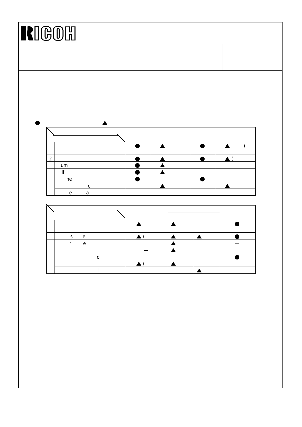
PROCESS CONTROL ADJUSTMENT CHART FOR MODEL A105
The following table indicates the tasks required, and their order, when you replace or
clean the OPC drums, developers, development unit(s), ID sensor(s), and/or when
installing a new machine.
l
: For all four colors (4C) s: Only for the relevant colors (1 to 3C) —: Don’t do it
Maintenance items
Necessary tasks, in order
1 Developer replacement
(including dev. roller cleaning)
2 ID sensor cleaning
3 Drum replacement
4 Self check 1 to 4
5 TD check - All Colors
TD check - 1 to 3 color(s) —
TD check - Manual — — — —
Maintenance items
Necessary tasks, in order
1 Developer replacement
(including dev. roller cleaning)
2 ID sensor cleaning
3 Drum replacement —
4 Self check 1 to 4 —
5 TD check - All Colors — — —
TD check - 1 to 3 color(s)
TD check - Manual — —
OPC drum replacement Developer replacement
4 drums 1 to 3 drum(s) 4 colors 1 to 3 color(s)
ls
ls
ls
ls
l
Development
unit replacement
s
( )
s
( )
s
( )
( )
( )
( ) — —
( ) — —
—
s
( ) —
ID sensor New machine
Replaced Cleaned
s
( ) —
s
( )
s
( ) — —
s
( ) — —
s
( ) — —
ls
ls
l
s
( )
s
( ) —
( )
( )
—
s
( )
installation
l
l
l
NOTE:
• Whenever OPC drums are replaced, replace the relevant color
developers for the drums as a set.
• Do the necessary tasks from top to bottom, in order.
• When two or more maintenance items are done at one time, combine
the necessary jobs for those maintenance items. Write the color
symbols of each relevant color in the space provided in brackets
( ).
• TD check for all colors includes that for 1 to 3 colors or manual TD
check. If both of these cases are marked, do only the TD check for
all colors.

Technical Bulletin No. RTB-001
SUBJECT: Process Control Adjustment DATE:November
30, ’95
PAGE: 4 of 5
SELF CHECK (1 to 4 Colors) FOR MODEL A105
CAUTION: Only change the data and perform the maintenance for
the relevant colors.
NOTE: The self check (1 to 4 colors) procedure should be performed,
1. when the drum(s) (1 to 4 colors) are replaced.
2. when the ID sensor(s) (1 to 4 colors) are replaced.
From the following steps, only perform the maintenance for the relevant colors.
1. When the relevant drums or "the ID sensors and the drums" are replaced, clean the
relevant development rollers and ID sensors, and replace the relevant developer.
2. Only set the SPD for the relevant color as follows:
• SPD#190 to H (SC#840 ∼ #843 off mode)
• SPD#611 ∼ #614 to 32 (ID Sensor LED Data)
(SPD#611: B k, #612: M, #613: Y, #614: C)
• SPD#110 ∼ #113 (Pointer data monitor/change) to 22
(SPD#110: B k, #111: M, #112: Y, #113: C)
• SPD#115 ∼ #118 (Pointer lower limit data monitor/change) to 18
(SPD#115: B k, #116: M, #117: Y, #118: C)
3. Make 5 copies of the C-4 chart on A3/11" x 17" size or A4/81/2" x11" paper.
(Do not make these copies in a continuous copy run. Make 5 single-copy runs.)
NOTE: If it is a solid copy, set the relevant charge corona unit in position.
4. Perform the relevant self check (SPD #525).
• Key an appropriate value into SPD#525, referring to the following notes:
• Press the Enter key while pressing the Start key to start.
NOTE: Select relevant colors for the self check by changing the value of SPD#525
from "15" to another setting (1 to 15).
1: Bk 4: Y 7: Bk+M+Y 10: M+C 13: Bk+Y+C
2: M 5: Bk+Y 8: C 11: Bk+M+C 14: M+Y+C
3: Bk+M 6: M+Y 9: Bk+C 12: Y+C 15: Bk+M+Y+C
(all colors)
 Loading...