

Ricoh NC8115.015 IMPORTANT SAFETY NOTICES

IMPORTANT SAFETY NOTICES
PREVENTION OF PHYS ICAL INJURY
1. Before disassembling or asse mblin g pa rts of the copie r and perip herals,
make sure that the copier power cord is unplu gg ed.
2. The wall outlet should be near the copier an d easily accessible.
3. Note that some compo ne nt s of th e copier and the paper tray unit are
supplied with electrical voltage even if the main switch is turned off.
4. If any adjustment or operat ion check ha s to be made with exterior covers
off or open while the main switch is turned on, kee p ha nds away from
electrified or mechanically drive n comp on ents.
5. If the hot roller temperature is lo w when the main switch is turned on, the
copier starts process cont rol self check au to matically. Keep hands away
from the mechanical and the ele ctrical components to avoid any injury.
6. The inside and the met al pa rts of the fusin g un it be come extremely hot
while the copier is operat ing . Be careful to avoid touching those
components with your bare hands.
HEALTH SAFETY CONDITIONS
1. Never operate the copier without the ozone filters installed.
2. Always replace the ozone filters an d th e ozone neutralizers with the ones
specified at the spe cifie d intervals.
3. Toner and developer are non-to xic, bu t if you get eith er of them in your
eyes by accident, it may cause temp ora ry e ye disco mfo rt. Try to remove
with eye drops or flush with wat er as first aid. If un succe ssfu l, ge t med ical
attention.
OBSERVANCE OF ELECTRICAL SAFETY STANDARDS
1. The copier and its peripherals must be insta lled and maintained by a
customer service represen tative who has completed the training course
on those models.
2. The RAM board on the main control board has a lithium battery which can
explode if replaced incorre ctly. Re pla ce th e ba tt ery on ly with an iden tica l
one. The manufacturer reco mmen ds replacing the entire RAM board. Do
not recharge or burn this ba tt ery. Used batteries must be handle d in
accordance with local regula tio ns.
1995 By Ricoh Company Ltd. All rights reserved

SAFETY AND ECOLOGICAL NOTES FOR DISP OS AL
1. Do not incinerate the toner bottle or the used toner. Toner dust may ignite
suddenly when exposed to open flame.
2. Dispose of used tone r, developer, and organic photoconductor according
to local regulations. (These are non-to xic supplies.)
3. Dispose of replaced parts in acco rda nce with local regulations.
4. When keeping used lithiu m bat teries in order to dispose of them later, do
not put more than 100 batteries per sealed box. Storin g larger nu mbe rs or
not sealing them apart may lead to che mical rea ctions and heat build-up.
LASER SAFETY
The Center for Devices and Radio log ical Hea lth (CDRH) prohibits the repair
of laser-based optical units in th e fie ld. The optical housing unit can only be
repaired in a factory or at a location with the requisite eq uipment. The laser
subsystem is replaceable in the field by a qualified Customer Engineer. The
laser chassis is not repairable in the field . Cust omer engineers are therefore
directed to return all chassis and lase r subsyst ems to the factory or service
depot when replacement of th e optical subsystem is required.
WARNING:
Use of controls, or adjustment, or performance of procedure s oth er th an
those specified in this manual may result in hazardous radiation exp osu re.
WARNING FOR LASER UNIT
WARNING:
CAUTION MARKING:
Turn off the main switch before atte mpting any of the
procedures in the Laser Unit sectio n. Laser beams can
seriously damage your eyes.

SECTION 1
OVERALL MACHINE
INFORMATION
5 January 1995 DIFFERENCES
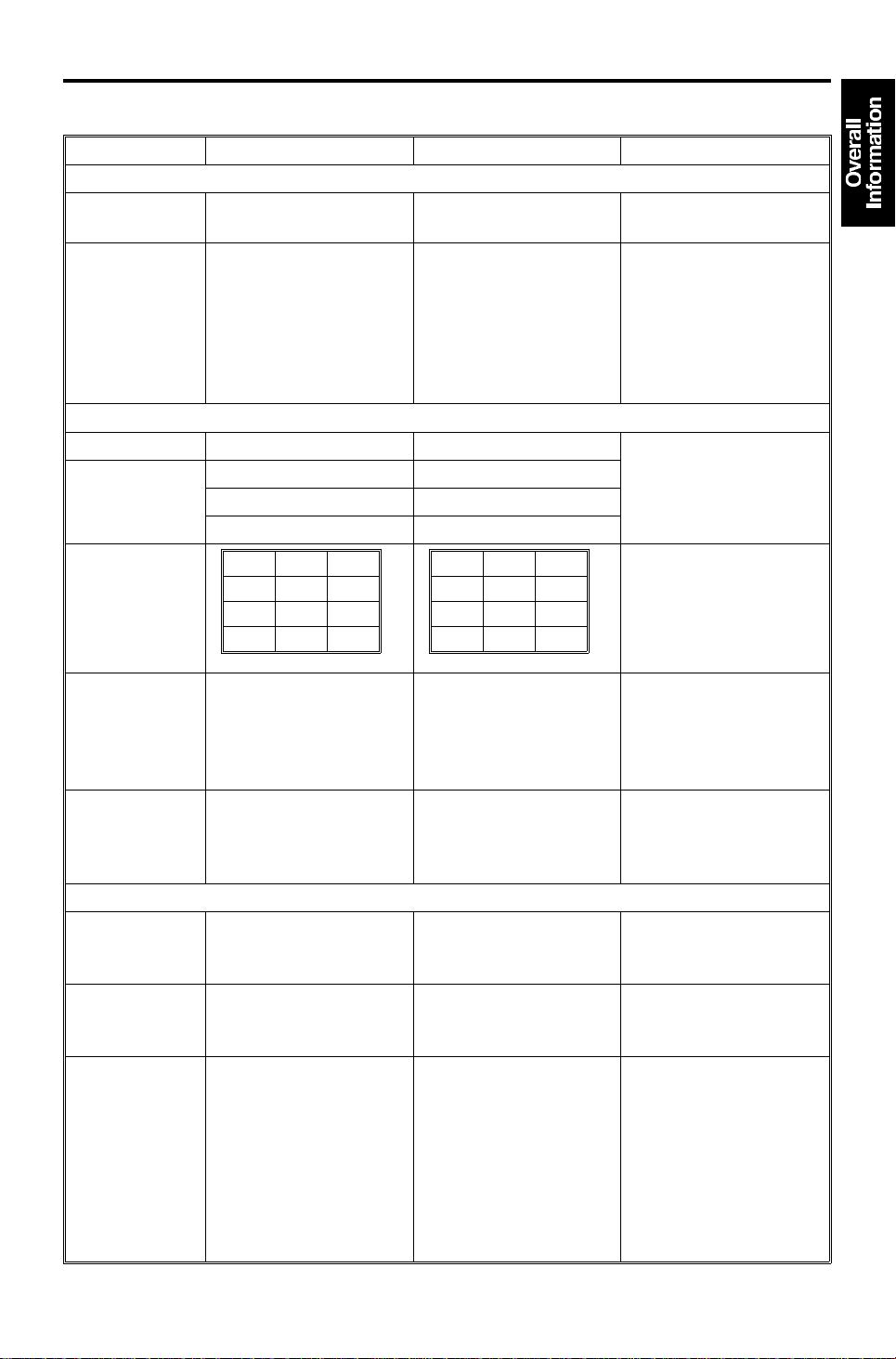
1. DIFFERENCES
DESCRIPTION MODEL A092 MODEL A105 Reason for modification
SCANNER
Resolution 16 lines/mm (406.4 dpi) 400 dpi To meet printer
standard.
CCD Drive
Board Set
IMAGE PROCESSING
Gradation 64 gradation 6 bit 256 gradation 8 bit To improve copy
Dithering
Pattern Matrix
RGBγ
Parameter
Memory 18 MBytes (1M x 144) 64 MBytes (4M x 128) An image defined at 8
4 Color
Developing
(Y, M, C, Bk)
LASER
Gradation 64 steps by using
Polygon Motor
Rotation Speed
Horizontal
Magnification
&
Printing Start
Adjustment
Method
CCD Drive Board CCD
Pre-amp Board and
Video Processing
Board
These boards have to
be replaced as a set.
Letter: 2 x 2 Letter: 1 x 1
Photo/Letter: 3 x 3 Photo/Letter: 2 x 1
Photo: 4 x 4 Photo: 2 x 2
LH
R65
G55
B75
Image repeat
Edit image
These cannot use
black developing.
dither matrix
(8 steps/pixel)
9000 rpm 8858.3 rpm As the resolution has
Adjusted by DGSs on
the drum exposure
control board.
CCD Pre-amp Board
has been eliminated.
CCD Drive Board and
Video Processing
Board these two
boards can be
replaced separately.
LH
R87
G86
B96
The functions at left
can now use black
developing.
256 gradation
(256 steps/pixel)
Adjusted keys on the
operation panel. (SP
mode)
To ease servicing.
quality.
To meet the new type
toner.
bits per pixel requires
much more memory
than one defined at 3
bits per pixel.
To improve the copy
quality.
To improve the copy
quality.
been changed from
406.4 dpi to 400 dpi.
To ease servicing.
1-1
[B]
DIFFERENCES 5 January 1995
DESCRIPTION MODEL A092 MODEL A105 Reason for modification
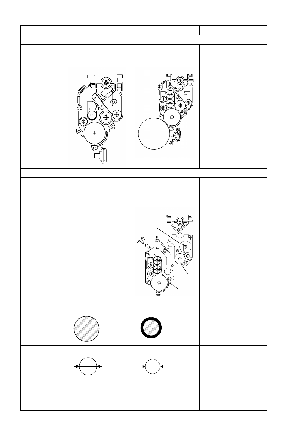
ID SENSOR
ID Sensor ID sensor is set on the
casing of the
development unit.
DEVELOPMENT UNIT
Unit Separation Cannot be separated
sub-tank from
main-tank.
ID sensor is set on the
casing of the copier.
Can be separated the
sub-tank [A] from the
main-tank [B]
When replacing the
development unit, it is
not necessary for
model A105 to perform
Vmin check.
Because, the ID sensor
is set separately from
the casing of the
development unit.
To replace the toner
supply roller [C].
Developer for
all colors
Toner
Diameter for
all colors
Toner Supply
Roller
[A]
[C]
Uncoated ferrite carrier. Silicon coated ferrite
carrier.
250 g/bag 200 g/bag
12 µm
Rubber roller Silicon rubber roller To improve toner
6.4 µm
To prolong the life of
the developer.
15K → 20K
To increase the charge
ability of the developer.
To improve the
resolution of copy
image.
supply capacity.
1-2
5 January 1995 DIFFERENCES
DESCRIPTION MODEL A092 MODEL A105 Reason for modification
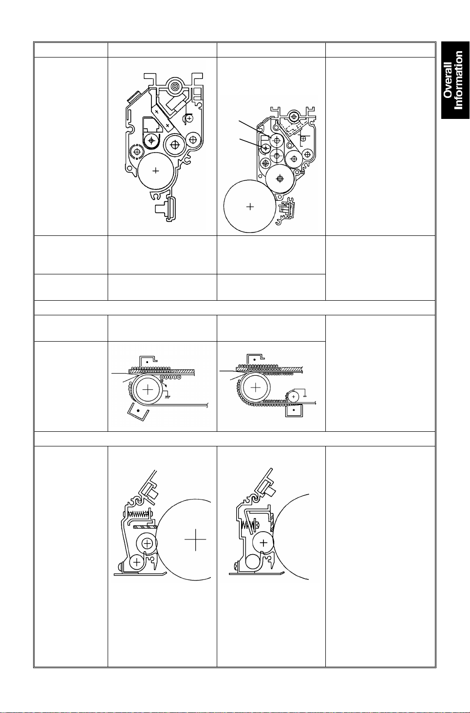
Cross-mixing
Mechanism
Add upper auger [A]
and upper transfer
roller [B].
[A]
[B]
To stabilize the image
density.
To eliminate the
un-even density band
(12 mm/0.47 inch
pitch).
To power up the mixing
function.
Bias
Development
Sleeve Speed
TRANSFER UNIT
Transfer Drive
Roller
Transfer Belt
Discharge
CLEANING UNIT
Cleaning
Method
–DC (–278V ∼ –678V)
Drum speed : Sleeve
speed = 1 : 2.3
Low impedance High impedance To insure cyan toner is
Trailing blade Counter blade The new toner consists
–DC+AC
DC (–278V ∼ –678V)
AC (1 kV peak to peak)
Drum speed : Sleeve
speed = 1 : 1.6
To get uniform density
on copies.
transferred to the copy
paper.
of smaller particles.
To remove the smaller
particles of the new
toner and to improve
the durability of the
cleaning blade.
1-3
DIFFERENCES 5 January 1995
DESCRIPTION MODEL A092 MODEL A105 Reason for modification
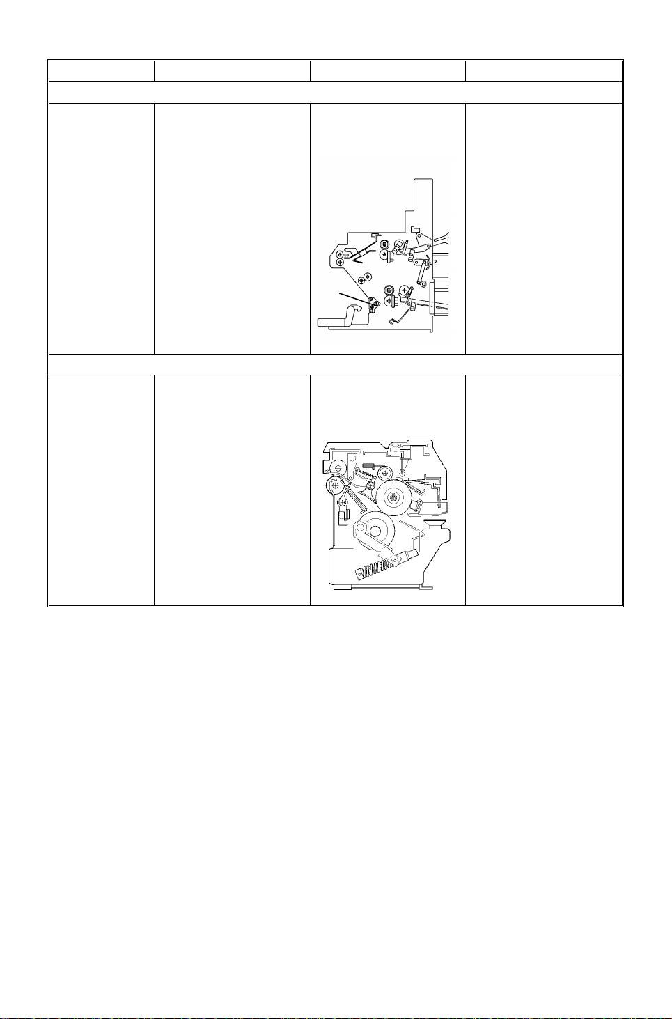
PAPER FEED UNIT
Paper Feed
Unit Parallel
Adjustment
Mechanism [A]
This mechanism has
been applied by the
engineering change.
This mechanism has
been applied from the
1st production run.
To adjust the skew and
the color layer
alignment at the trailing
edge.
[A]
FUSING
Hot Roller
Cleaning
Mechanism
Not Used A cleaning roller and
cleaning scraper have
been added.
To increase durability
of fusing unit.
NOTE: This is not a complete list of the differen ces be twe en the mo del A09 2
and A105, but does illustrate the major differences.
1-4

5 January 1995 SPECIFICATIONS
2. SPECIFICATIONS
Configuration: Console type
Copy Process: Laser electrostatic transf er/ tetradrive system
Originals: Book/sheet, fixed plate n
Original Alignment: Front-right corner
Maximum Original Size: A3, 11" x 17"
Copy Paper Size: Maximum: A3, 11" x 17
Minimum: A6 (lengthwise only), 51/2" x 81/2"
Copy Paper Weight: 64 to 157 g, 17 to 42 lb
(Paper with more than 128 g/34 lb and OHP film
should be used with Thick Paper/OHP mode.)
Copy Speed: <Model A092>
14.5 cpm/81/2" x 11" sideways, or smaller
15 cpm/A4, sideways, or smaller
7.5 cpm/A3, 11" x 17"
<Model A105>
15 cpm/81/2" x 11" sideways, or smaller
15 cpm/A4, sideways, or smaller
7.5 cpm/A3, 11" x 17"
(In thick paper/OHP mode, copy speed is reduced
to one half. )
First Copy: 18 seconds/A4, 81/2" x 11" sideways
(In thick paper/OHP mode, it is 35 seconds.)
Warm-up Time: Within 8 minutes (at room temperature 20°C/68°F)
Copy Counter: 1 to 99
(Maximum set number is adjustable with SP38.)
Automatic Reset: After 60 seconds (Adjustable from 1 to 180
minutes, or no reset with SP37 .)
Photo Conductor: Organic photoconductor (OPC) drum, 60 mm in
diameter, 4 drum system driven by a dc servo
motor through a single drive shaft (tetradrive).
Drum Charge: Single wire with grid plate (negative charge),
variable grid voltage type.
1-5

SPECIFICATIONS 5 January 1995
Fixed Reproduction
5 enlargement ratios and 7 redu ctio n ratios
Ratios:
Letter Version A4 version
1 : 4.00 400% copy 1 : 4.00 400% copy
1 : 2.00
1 : 1.55
1 : 1.29
1 : 1.21
1 : 1 100% copy 1 : 1 100% copy
1 : 0.93 To create margin 1 : 0.93 To create margin
1 : 0.85
1 : 0.77
1 : 0.74
1 : 0.65
1 : 0.50
1 : 0.25 25% copy 1 : 0.25 25% copy
5
1/2" x 81/2" ⇒ 11" x 17"
5
1/2" x 81/2" ⇒ 81/2" x 17"
8
1/2" x 11" ⇒ 11" x 17"
8
1/2" x 14" ⇒ 11" x 17"
8
1/2" x 13" ⇒ 81/2" x 11"
8
1/2" x 14" ⇒ 81/2" x 11"
11" x 15" ⇒ 8
11" x 17" ⇒ 8
11" x 17" ⇒ 5
1/2" x 11"
1/2" x 11"
1/2" x 81/2"
1 : 2.00
1 : 1.41
1 : 1.22
1 : 1.15
1 : 0.82
1 : 0.75
1 : 0.71
1 : 0.65
1 : 0.50
A5 ⇒ A3 A6 ⇒ A4
A4 ⇒ A3 A5 ⇒ A4
F ⇒ A3 A4 ⇒ B4
B4 ⇒ A3
F ⇒ A4 B4 ⇒ A4
B4 ⇒ F4 B4 ⇒ F
A3 ⇒ A4 A4 ⇒ A5
A3 ⇒ F
A3 ⇒ A5 A4 ⇒ A6
Reproduction error:
±0.5% for full size mode, ± 1.0% for other ratios.
Zoom: From 25% to 400%, 1% steps
(In thick paper/OHP mode, from 25% to 200% )
Scanning System: One way scanning with optical fiber arra y and full
size color CCD’s, single scan with simultaneous
B, G, R, color separation.
<Model A092> 16 dots/mm, 256 gradation
<Model A105> 400 dpi, 256 gradation
Scanner Light Source: Two fluorescen t lamp s
Drum Exposure System: 4 semiconductor lase r bea ms (1 la ser beam pe r
OPC drum), one dimensional simultaneous
scanning onto 4 drums with one polygon
motor/two polygon mirrors.
<Model A092> 16 dots/mm, 64 gradations
<Model A105> 400 dots/inch, 256 gradations
Development: Dual component dry toner/single development
roller system. (Negative toner charge/Negative
drum charge process.)
Developer: <Model A092>
- Bk, Y, C: 250 g/bag
- M: 200 g/bag (same as that of model A105)
<Model A105>
- Bk, M, Y, C: 200 g/bag
1-6

5 January 1995 SPECIFICATIONS
Toner: <Mod el A0 92>
- Bottle Type: 400 g/bo ttle
- Consumption: 9000 copies/A4, 81/2" x 11"
(5% image area for each color)
<Model A105>
- Bottle Type: 340 g/bottle
- Consumption: 7000 copies/A4, 81/2" x 11"
(5% image area for each color)
Development Bias: <Model A092> Negative dc variable bias
<Model A105>Negative dc and ac variable bias
Image Transfer: Single wire dc positive charge from the reve rse
side of the transfer belt.
Paper Transport: One flat transf er be lt syste m
Paper Separation: Primary: Paper curvature separation
Secondary: Pick-off pawls, and single wire
separation ac corona fo r pa per
discharge.
Transfer Belt Discharge: <Model A092> Single wire ac corona
<Model A105> Single wire ac corona and
discharge roller
Transfer Belt Cleaning: Blade and brush cleaning
OPC Drum Cleaning: <Model A092> Trailing blade and brush
cleaning
<Model A105> Counter blade and brush
cleaning
Quenching: Photo quenching by LEDs
Paper Feeding: Dual cassettes (500 sheet capacity each ), an d a
bypass feed table (20 shee ts)
Paper Feed System: Feed and reverse roller (FRR) system
Image Fusing: Hea t an d pressure type with silicone oil. Silicone
hot-roller, and silicone pressure roller.
Fusing Lamp: Halogen lamp (220 – 240 V/550 W, 115 V/550 W)
Silicone Oil Consumptio n: 350 cc per 35,000 copies (A4/81/2" x 11")
Copy Tray Capacity: 100 sheets
1-7

SPECIFICATIONS 5 January 1995
Self-diagnostic Codes: 72 codes
Process Control: Drum potential control
Development bias control
Toner supply roller bias contro l
Copy Counters: Two counters (Double count mode for A3/DLT
can be set with SP45.)
• Single color copy counter (inclu din g bla ck)
• Full color copy counter
User Code Mode: 2 0 4 digits numbers from 0001 to 9999
Power Source: 220 – 240 V/50 Hz: 8 A
115 V/60 Hz: 12 A
Power Consumption: Maximum: 1.4 kW
Warm-up: 0.9 kW (average)
Ready: 0.5 kW (average)
Copy cycle: 1.0 kW (average)
Dimensions (W x D x H): Main frame only: 930 mm x 725 mm x 930 mm
(36.6" x 28.5" x 36.6")
With platen cover, copy tray, and A3/DLT
cassette in the lower fee d sect ion:
1695 mm x 725 mm x 954 mm
(66.7" x 28.5" x 37.6")
Weight: Main frame only without consumables:
<Model A092> 285 kg (628.3 lbs) or less
<Model A105> 285 kg (628.3 lbs) or less
Main frame with consumables:
<Model A092> 296 kg (652.6 lbs) or less
<Model A105> 300 kg (661.4 lbs) or less
Optional Equipment: - Editor (This is standard for Model A105.)
- SPU SPU(Model A984-27) can only be connected
to Model A092-25 and A092-27.
SPU (Model A711-27) can be connected
to Model A105-25 and A105-27.
SPU(Model A984-17) can be connected
to Model A092-17 and A105-17.
- Key counter (locally procured)
1-8

5 January 1995 SPECIFICATIONS
<Additional Features>
User Program Mode: 5 modes (The image repeat mode and the poster
mode can not be stored as a program mode.)
Original Recognition
Mode:
The default is the Off mode. Using SP-31, the On
mode can be selected. In AP S/ARE, Centering,
Mirroring, Slanted Image modes, the On mode is
automatically selected.
Color Selection: The default is Full Color. Using SP-44, the Black
mode can be selected as th e de fault mode.
Single color: 9 kinds
black, yellow, orange, red, magenta, blue,
cyan, green, light green .
Optional single color:
3 user programmable colors can be registered.
Original Modes: 4 modes
- Automatic Letter/Photo separation (Auto)
mode: Default
- Letter mode
- Letter/Photo mode
- Photo mode
The default mode can be changed by SP40, and
41.
In the Auto mode, photo areas are processed
using the Phot o mode as a default.
(It can be changed from Photo mode to
Letter/Photo mod e with SP43.)
APS: Pre-scanning type
Paper Weight: Thick Paper/OHP mode:
Process speed is changed from 75 mm/sec. to
37.5 mm/sec. This mode is for paper that is
128 g/34 lb or heavier and for OHP film.
Thin Paper:
The fusing temperat ure during the copy run is
controlled at 143°C (131°C for mo del A 105) rather
than 148°C (135°C for model A105). (By SP 42 ,
the default mode can be set at the Thin Paper
mode.)
1-9

SPECIFICATIONS 5 January 1995
Special Reduce/Enla rge : - ARE (Auto Reduce/Enlarge)
- Directional size magnification
- Directional magnification
- Size magnification
- Zoom
Edit Image: - Centering
- Save area
- Delete area
Image Creation: - Outline mode
- Positive/Negative mode
- Shadow mode
- Image Repeat mode
- Mirror Image mode
- Slanted Image mode
- Poster mode (Model A105 only)
Color Creation: - Color Background mode
- Color Conversion mode
- Pastel Image mode
- Posterization mode
- Solarization mode
- Mosaic mode
<Image Adjustments>
Image Density Selection: 9 ste ps
Color Balance: For black, cyan, magenta, and yello w, ad just ab le
in 9 steps. Adjusted balance can be stored as a
default setting by pressin g th e Ba lance Memory
key.
Color Adjustment: Colo r t one of gree n, cyan, blue , mag en ta, red, or
yellow can be independently adjusted to one of
the neighboring colors. This can be done with up
to three colors.
Sharp/Soft: Adjusts the sharpness of the copy image.
Contrast: Adjusts the contrast bet ween light and dark parts
of the copy image.
Background Density
Adjusts background image density of the copy.
Control:
1-10

5 January 1995 SPECIFICATIONS
User Tool/Service Tool:
<Model A092>
For users
For service
<Model A105>
For users
For service
10 user tools (UT-1 to UT-10) for 115 V version
11 user tools (UT-1 to UT-11) for 230 V version
SP mode (SP-1 to SP-92)
SPT/SPD mode
SP Test mode (SPT-0 to SPT-119)
SP Data mode (SPD-1 to SPD-898)
11 user tools (UT-1 ∼ 10 and 12) for 115 V version
12 user tools (UT-1 ∼ 12) for 230 V version
SP mode (SP-1 to SP-95)
5 SP modes have been added from model A092.
SPT/SPD mode
SP Test mode (SPT-0 to SPT-119)
SP Data mode (SPD-1 to SPD-898)
1-11
COPY PROCESS 5 January 1995
3. COPY PROCESS
3.1 OVERVIEW
[E]
[D]
[C]
[B]
[A]
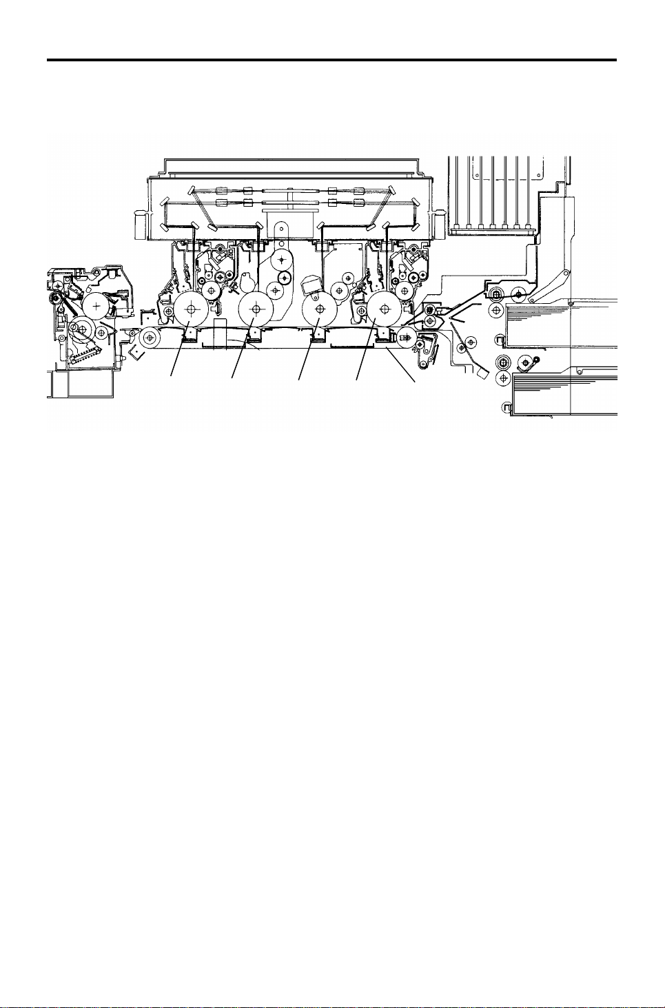
The main marketing strengt hs of this cop ier are:
1) High productivity with the world’s fa ste st dig ital full color copy speed
(15 cpm/A4, 14.5 cpm/LT: Model A092, 15 cpm/A4, LT: Model A105).
2) A wide variety of copy paper can be use d, such as he avy pa pe r (up to
157 g/42 lb), and small paper (up to A6 lengthwise or 5 1/ 2 " x 81/2").
To achieve this productivity, this machine adapts four OPC drums, fo ur laser
beams, and one time scanning with a simultaneous B, G, R, (Blue Gre en
Red) color separation system (tetradrive system). Paper is transported on a
flat transfer belt [A] where the toner image on each drum is transferred to the
paper in order. These four layers of color to ne r image are fused on the paper.
For compactness, each drum is 60 mm in diame te r, an d th ey are located at
110 mm intervals. From the right side , th e drums are: black [B], magenta [C] ,
yellow [D], and cyan [E]. Ea ch drum has the following compon en ts aro un d it:
• Charge corona unit
• Development unit
• ID sensor
• Transfer corona unit (below the transfer belt)
• Drum cleaning unit
• Quenching lamp (LEDs)
1-12
5 January 1995 COPY PROCESS
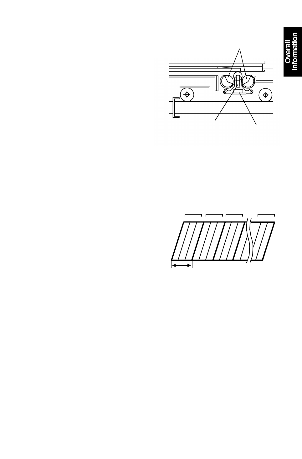
3.2 SCANNING
3.2.1 O riginal Scanning
The color original is illuminate d by two
exposure lamps [A]. Reflected light
from the original passe s through the
optical fiber array [B] to the full size
color CCD [C].
(CCD = Charge coupled device)
The CCD converts the light intensity to
an electrical value.
The scanner which is composed of th e
exposure lamps, optical fib er arra y, an d
CCD, is always in contact with the
exposure glass while scanning.
3.2.2 P hoto-electric Conversion
[B]
[A]
[C]
The full size color CCD has blue, green,
or red filters on each picture element
(pixel) in a line. Three elements, with
1 2880/chip23
B G R B G R B G R
the filters for each color, are used as
one unit for color separation of the
original image.
<Model A092>
16 pixels per 1 mm = 406.4 pixels per
inch (DPI)
62.5 µ (Model A092)
63.5 µ (Model A105)
<Model A105>
400 pixels per inch (DPI)
The CCD converts the light intensity
into an electrical analog signal.
3.2.3 Analog-digital Conversion
The analog signal outp ut from the CCD is digitized. Eight bit s are used for
each picture element (pixe l), which gives 256 gra da tio n ste ps.
3.2.4 RGB Separation
Signals from the 14,60 0 pict ure elements are separate d int o th ree groups of
red, green, and blue picture elements.
1-13
COPY PROCESS 5 January 1995
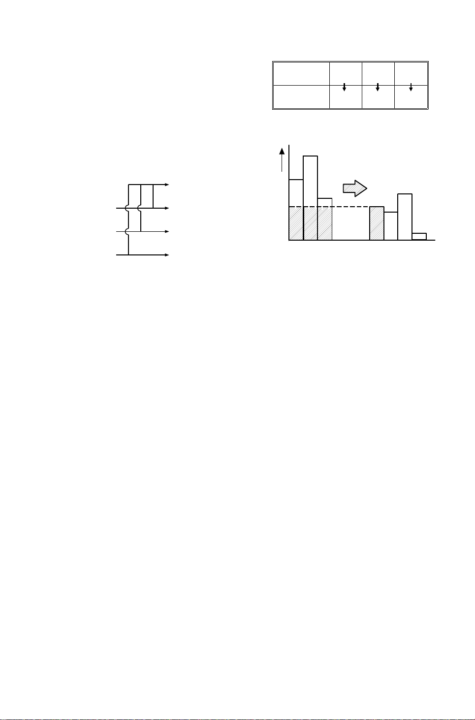
3.2.5 Image Processing
Image processing fo r various copy
Filter B G R
modes is done in the image processing
PCB’s.
Toner Y M C
The 8-bit gradation digital data for one
set of red, green and blue elements is
changed to the data for four toner
200
colors:
150
Black data (Bk)
Green data (G) Magenta data (M)
Blue data (B) Yellow data (Y)
Red data (R) Cyan data (C)
100
80
CMY BkC MY
(UCR Ratio: 80%)
80
120
70
20
The black output is determined by the CMY data (which is a result of the
RGB data). A common value is su bt racted from the C, M, and Y values and
this value becomes the black value. This is called UCR (Unde r Color
Removal).
<Model A092>
There are 8 laser exposure grad ation steps (7 levels + laser off), so only 3
data bits are needed. The four color da ta are con vert ed from 8-b its to 3-bit s.
64 kinds of 4 x 4 bit dither matrices (Photo mode) a re use d to make 64
gradations of the copy image.
<Model A105>
There are 256 laser exposure gradation steps (255 levels + laser off), so
8 data bits are needed. One pixel ca n mak e 256 gra dations of the copy
image.
1-14

5 January 1995 COPY PROCESS
3.3 LASER EXPOSURE
1. There are four laser beams (one beam per drum) and two polygon
mirrors in the laser unit. The two polygon mirrors are turne d using one
motor.
The laser beam is reflected by the turn ing polygon mirror, and passes
through a complex lens (called the f θ lens) to the drum.
Using one surface of the po lygo n mirror, one main scan line is made. The
main scan direction is:
1st (black) and 2nd (magenta) drums: front to rear.
3rd (yellow) and 4th (cyan) drums: rear to front.
2. The laser beam switches on an d of f at very high frequency to make an
image with 16 dots/lines per 1 mm (400 dpi for Model A105).
<Model A0 92>
Furthermore, the on-time (PWM) per dot for th e laser bea m is contro lled
in 8 steps based upon the 3-bit data sent from the image processing unit.
<Model A105>
Furthermore, the on-time per dot for the laser beam is controlled 256
steps based upon the 8-bit data sent from the image proce ssing unit.
As a result, the negatively charge d dru m pot ential drops to the
appropriate level, fo rming an electrical latent image on the drum.
Unlike other PPCs, the exposed areas correspond to the dark image
areas on the original (ima ge area expo sure).
3. The data for black is sent just aft er image processing to the laser unit for
laser exposure on the black drum.
However the data for the other three colors is stored in the memory
board, and is sent to the laser unit at the app rop riat e time . This is t o align
the horizontal direction of the image deve lop ed on each of the four drums.
1-15
COPY PROCESS 5 January 1995
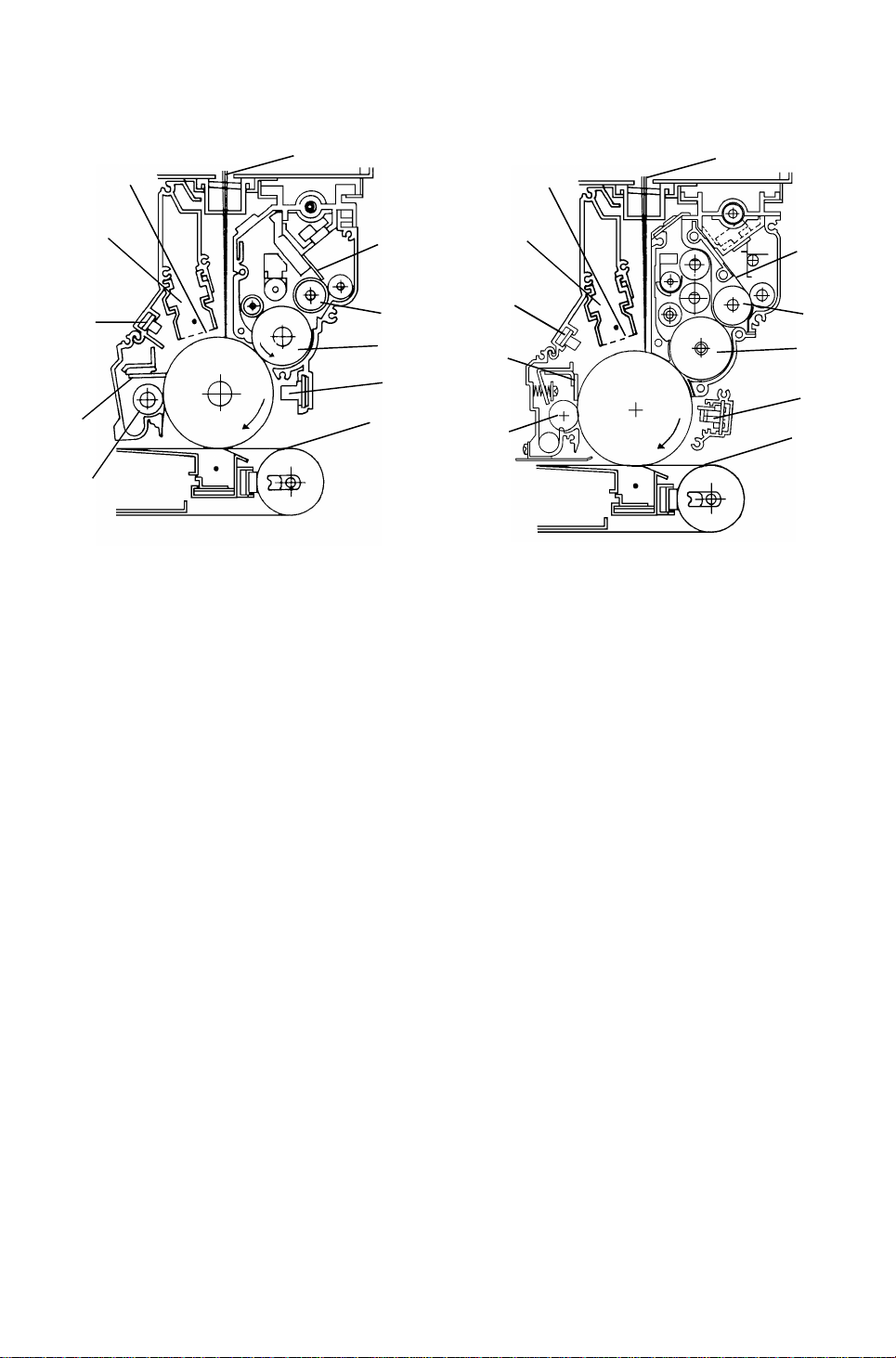
3.4 DRUM PROCESSES
[A]
[K]
<Model A092> <Model A1 05>
[D]
[B]
[F]
[E]
[C]
[B]
[A]
[K]
[I]
[D]
[G]
[I]
[H]
[J]
[J]
3.4.1 Charge
<Model A092 & A105>
In the dark the charge corona unit [A] applies a ne gative charge to the drum.
The grid plate [B] ensures that the charge is applied un iformly and that the
amount of the charge applied is correct. The charge remain s o n th e surf ace
of the drum because the photoconductive drum has a high electrical
resistance in the dark.
[F]
[E]
[C]
[G]
[H]
3.4.2 Development
<Model A092 & A105>
The magnetic developer brush on th e development roller [C] comes in
contact with the latent imag e on the drum surf ace. Negatively charged toner
particles are electrostatically at tracted to the areas of the drum surface whe re
the laser [D] has reduced the negative charge on the drum.
Unlike most PPCs, this machine uses a Neg at ive/Negative development
system. (Negative/Nega tive : Neg ative toner developed on a negative ly
charged drum.)
Another unique point is how the toner is supp lied to th e de velo pe r. Ton er is
supplied in an even and th in laye r o n th e sup ply roller [E] using a metering
blade [F].
While toner is passing the metering blade, the toner becomes negatively
charged, and is caught by the positively cha rged carrier in the development
unit.
1-16

V0
(= V )
L0
V
L1
V
L3
V
L7
VB
5 January 1995 COPY PROCESS
3.4.3 ID Sensor
The ID sensor [G] is used to detect the
different kinds of patterns developed on
the drum. It has two basic functions.
It’s used to control the density of tone r
in the devel oper.
It’s used to select the best process
conditions such as, charge grid volt age
[V0], development bias [VB] and laser
power (remaining or residual drum
voltage after level 3 exposure [VL3]:
Development Potential : VB – VL3
A092/ level 4 exposure [VL4]: A105).
3.4.4 Image Transfer
Copy paper is fed to the transfer belt [H] by the registra tio n rolle rs. A positive
charge is applied to the ba ckside of the paper through the tra nsfer belt. This
charge pulls the toner particles on the OP C drum surface onto the copy
paper.
After the first toner transfer (black), th e entire copy pape r is electrica lly held
on the belt’s surface.
Transfer charge for mag en ta , yellow, and cyan is stepped up to pull a new
color toner layer onto the paper.
3.4.5 Paper Separation
The paper’s stiffness causes it to sep ara te from th e transfer belt when the
belt turns sharply at the sep aration point. This is called "curvatu re
separation". To ensu re separation of paper that has low stiffness, this
machine also uses a separa tio n corona, for paper potent ial discharge, and
pick-off pawls. Three pick-off pawls to uch the belt just befo re th e lea din g
edge of the paper reaches the pick-off position.
3.4.6 Drum Cleaning and Quenching
The cleaning blade [I] and cleaning brush [J] remove an y ton er rema ining on
the drum surface and the toner is carried to the toner collection bottle.
The quenching lamp (LEDs) [K] electrically neutralize the surface of th e drum.
1-17

COPY PROCESS 5 January 1995
3.4.7 Transfer Belt Discharge and Cleaning
After paper separation , the resid ua l elect rical po te nt ial is discharged by the
belt discharge corona. Then , an y toner remaining on the belt surface is
removed by the belt cleaning brush and blade.
1-18
[A]
5 January 1995 COPY PROCESS
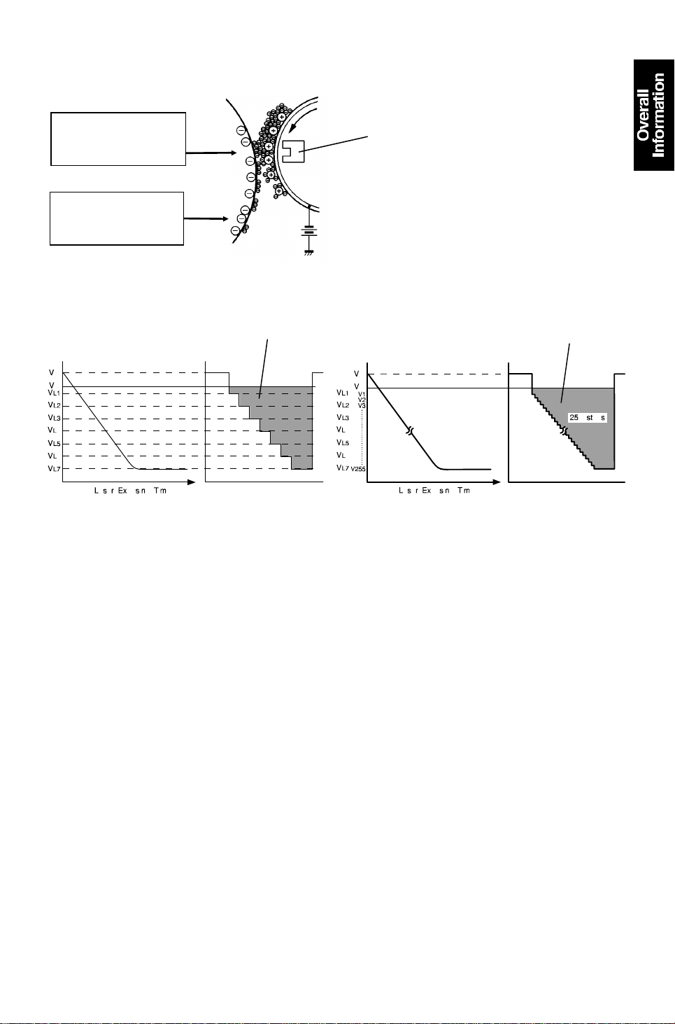
3.5 NEGATIVE/NEGATIVE DEVELOPMENT PROCE SS
VL1 : ∼ VL7
Drum voltage on the
image areas
(exposed by laser).
V0 :
Drum voltage on the
nonimage areas
(background).
VB
<Model A092>
Example = Pointer 10
0: –510V
V
B: –408V
V
L3: –282V
V
Example = Pointer 22
Development
Potential
<Model A105>
0: –698V
V
B: –561V
V
L3: –396V
V
Development
Potential
Most copiers use either a positively charged photoconductor and negat ively
charged toner or a negatively charg ed photo con du cto r a nd posit ively charged
toner. This is known as positive/n egative development. However, this
machine uses a negative/negative process where both the drum surface
charge and the tone r charge are negative.
Several forces interact in th e de velo pment process to produce a visible
image on the OPC drum. These forces are the charge pat te rn of the latent
image, the developme nt bias, the magnetic field of the de velo pment roller,
the positive triboelectric charge of the carrier, and the negative triboelectric
charge of the toner.
One of the most importan t of these forces is the charge patt ern of th e latent
image on the drum. To make the late nt image, the laser exposes an area of
the drum surface. The laser on-time for on e pulse is co nt rolle d using a pulse
width modulation circuit (PWM).
<Model A092>
The on-time is determined according the 3-bit data sent from the IPU (10 ∼
120 nsec).
<Model A105>
The on-time is determined accordi ng to the 8-bit data se nt from the IP U
(2 ∼ 86 nsec).
1-19

COPY PROCESS 5 January 1995
VD: Drum charge potential
V0: Non exposed area (Non imag e are a on origin al) = VD
<Model A092>
V0: Remaining drum voltage at laser dat a 0 (No lase r expo sure)
VL1: Remaining drum voltage at lase r dat a 1 (Sh ort est pha se)
|
VL7: Remainin g drum voltage at laser data 7 (Full phase)
<Model A1 05>
V0: Remaining drum voltage at laser dat a 0 (No lase r expo sure)
VL1: Remaining drum voltage at lase r dat a 34
VL2: Remaining drum voltage at lase r dat a 46
VL3: Remaining drum voltage at lase r dat a 63
VL4: Remaining drum voltage at lase r dat a 80
VL5: Remaining drum voltage at lase r dat a 127
VL6: Remaining drum voltage at lase r dat a 191
VL7: Remaining drum voltage at lase r dat a 255 (Lo ng est phase)
256 step laser exposure is used for copying. 7 step (VL1 ∼ VL7) laser
exposure is for process control.
<Model A092 & A105>
The power pack for each drum applies a dc negative bias [VB] (75 ∼ 160 V
lower than V0) to the developme nt roller sleeve. The main magnet [A] is
located inside the sleeve, facing the drum.
The toner is negatively charged and the carrier is positively charged due to
the agitation of th e toner and developer inside th e de velo pment unit (tribo
electric charge).
In a negative/negative process, toner particle s are at tra cte d to the drum
areas exposed by the laser hence, to the lower drum potential areas.
Development poten tial is the gap from VB (bia s) to VLX (Laser exposed area,
X=1 to 7).
1-20
5 January 1995 COPY PROCESS
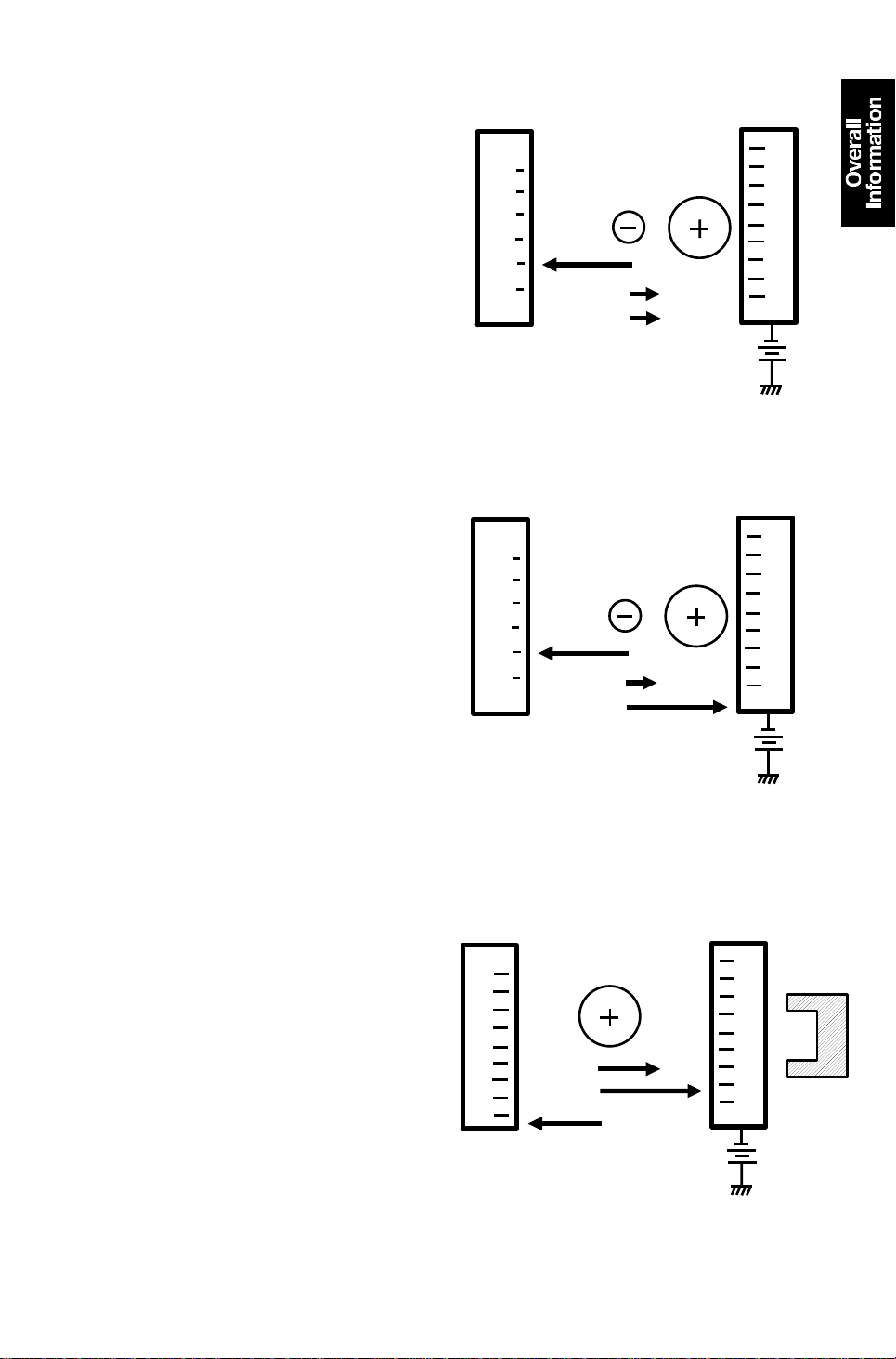
In the development area , the following
forces act on the toner particles:
Fc: The attractive force between toner
(–) and carrier (+)
FD: The repelling force between toner
(–) and the drum charge (–)
FB: The repelling force between the
toner (–) and the devel opment
roller bias (–)
The forces on the expo sed areas of the
drum are such that:
FB > FC + FD (Fig. 1)
This means toner is repelled from the
carrier to the drum. (FD is very small in
the image areas.)
The non-exposed areas of the drum are
such that.
FB < FC + FD (Fig. 2)
Here FD is very large and repels toner
from the non image areas.
You might expect that the positively
charged carrier would be attract ed to
the negatively charged nonima ge area s
of the drum. However, this does no t
happen. In the de velopment area, the
following forces act on the carrier
particles:
FMC:The attractive force of the magnet
on the carrier
DRUM
VL
Fig. 1
DRUM
VD
Fig. 2
DRUM
VD
F
F
B
B
Carrier
Toner
Toner
Fc
F
Fc
F
DEV.
ROLLER
Carrier
D
BIAS
DEV.
ROLLER
Carrier
D
BIAS
DEV.
ROLLER
MAGNET
FBC: The attractive force between the
carrier and development bias
FDC: The attractive force be twe en the
carrier (+) and the non-exposed
areas of the drum (–)
Since FDC < FMC + FBC (Fig. 3), the
carrier remains on the developmen t
roller’s sleeve.
1-21
Fig. 3
F
BC
F
MC
F
DC
BIAS
COPY PROCESS 5 January 1995
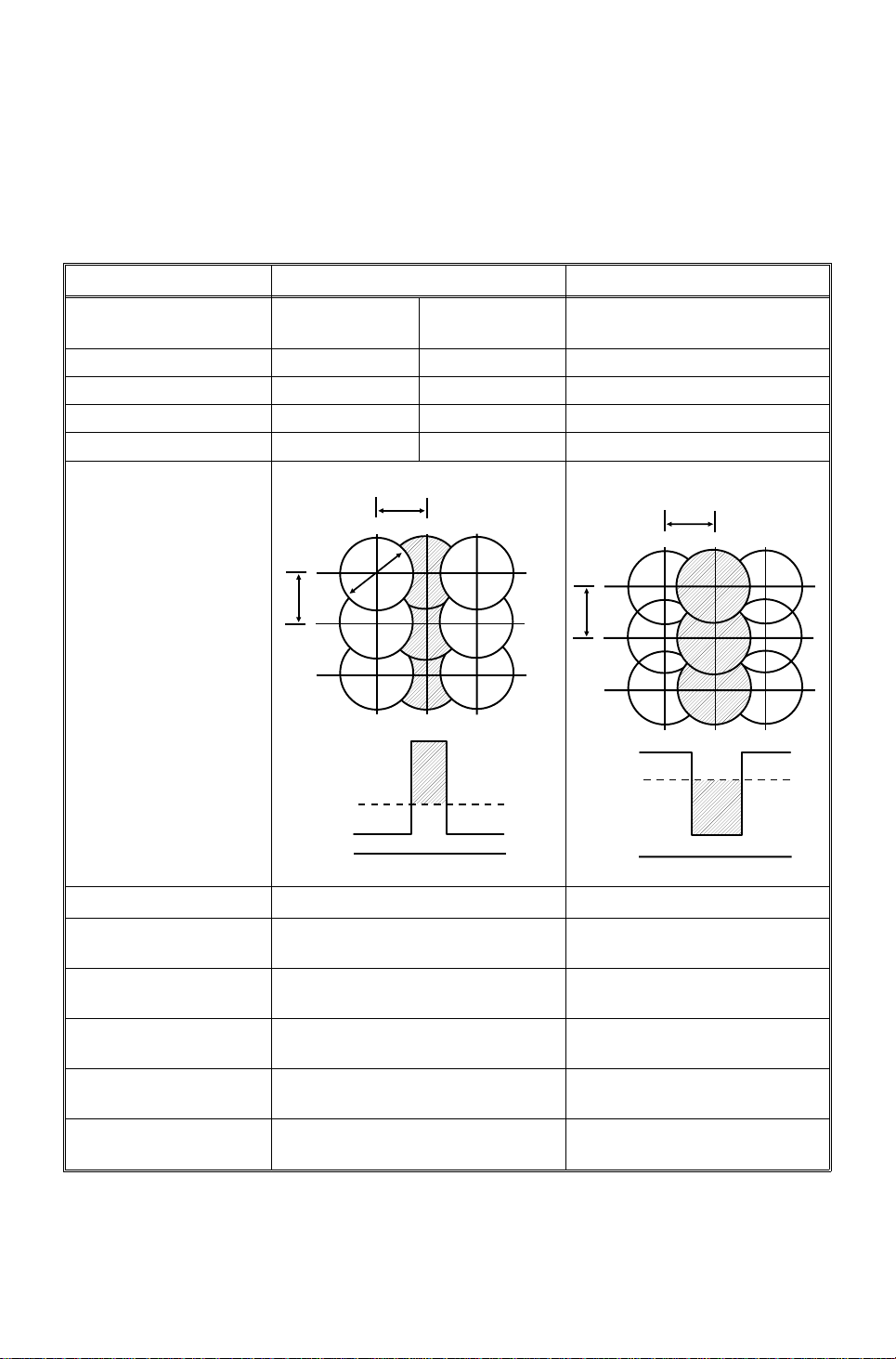
Positive/Negative Development VS. Negative/Negative Development
(2-component dry development process)
In a negative/negative process, some copy problems are exactly opposite to
what many copier service people have in tuitively come to expect. The table
below gives some of the diffe ren ces be twe en the posit ive/negative process
and the negative/negative process.
Positive/Negative Negative/Negative
Type of Laser He-neon
(gas, 630 nm)
Photoconductor Se Drum OPC OPC
Charge Corona Positive Negative Negative
Carrier Charge Positive Negative Positive
Toner Charge Negative Positive Negative
Photoconductor
Background exposure Image exposure
Exposure
He-neon or
semiconductor
P
Semiconductor
(765 ∼ 795 nm)
P
P: Pitch (1/16mm +
62.5µ for model
A092, 63.5µ for
model A105)
D: Laser beam
diameter
V
D: Drum voltage
B: Bias voltage
V
R: Residual voltage
V
Copy Problems
1. No photoconductor
charge
2. Low photoconductor
charge
3. High development
bias
4. Low development
bias
5. Stained toner shield
glass
D
P
VD
V
V
0V
P
B
R
White copy Black solid copy
Low image density Dirty background
Low image density Dirty background
Dirty background Low image density
Black stripes White stripes
D
V
V
B
0V
1-22
5 January 1995 MECHANICAL COMPONENT LAYOUT
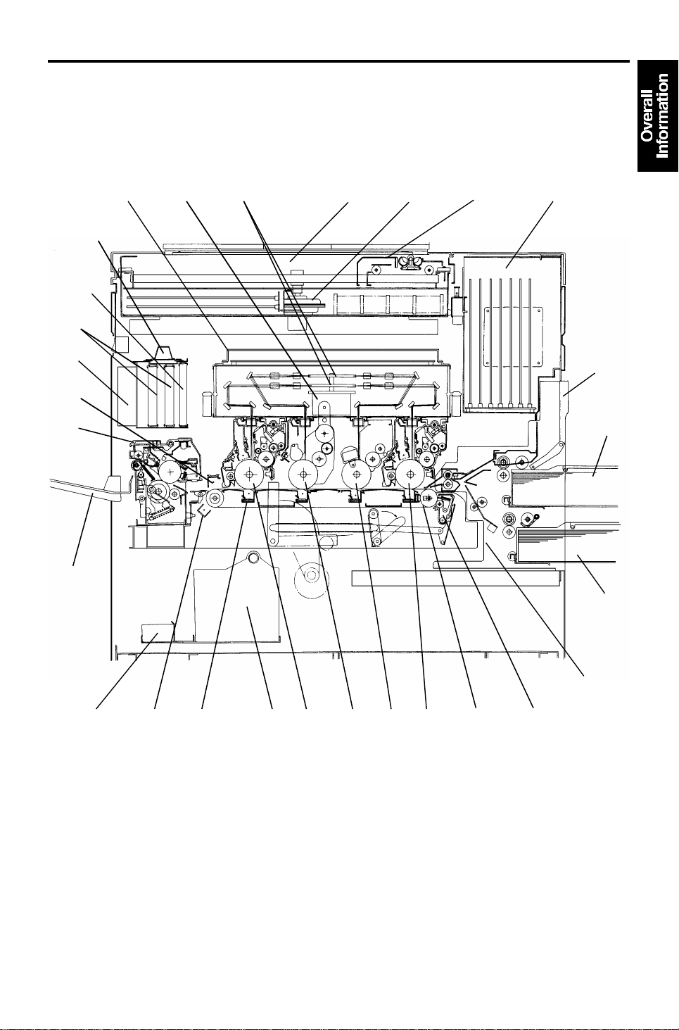
4. MECHANICAL COMPONENT LAYOUT
26
25
24
23
22
28
27
12
3
45
67
8
9
1-23
10
11
1415161718192021
13
12

MECHANICAL COMPONENT LAYOUT 5 January 1995
1. Laser Unit
2. Polygon Motor
3. Polygon Mirrors (2 pcs)
4. Scanner Unit
5. Scanner Motor
6. Scanner
7. IPU Section (7 PCB’s)
8. By-pass Table
9. Upper Cassette
10. Lower Cassette
11. Paper Feed Unit
12. Transfer Belt Cleaning Unit
13. Transfer Belt Unit
15. Magenta OPC Drum
16. Yellow OPC Drum
17. Cyan OPC Drum
18. Toner Collection Bott le
19. Transfer Corona (4 pcs)
20. Belt Discharge Corona
21. Developer Catch Pan
22. Copy Tray
23. Fusing Unit
24. Separation Corona
25. Fusing Exhaust Fan (2 pcs)
26. Exit Ozone Filters (2 pcs)
27. Dust Filter
14. Black OPC Drum
28. Ozone Neutralizer
1-24
11
12
4
13
14
5 January 1995 DRIVE LAYOUT
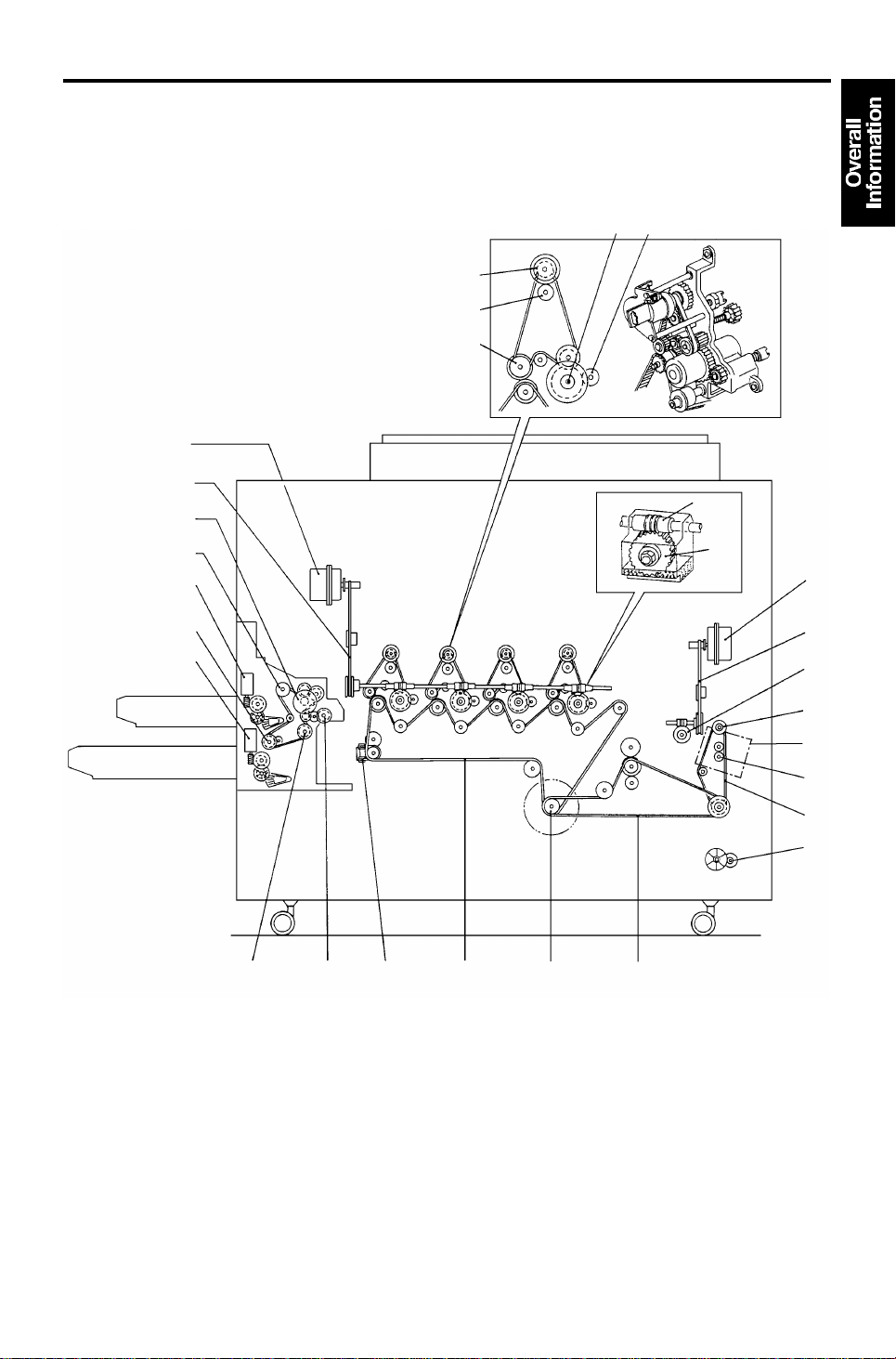
5. DRIVE LAYOUT
15
16
17
18
19
20
21
22
10
23
24
25 26
9
8
7
27
28
6
5
1
23
1-25

DRIVE LAYOUT 5 January 1995
1. Toner Collection Coil Drive Belt
2. 1st Timing Belt
3. Main Motor
4. 2nd Timing Belt
5. Developer Removal Motor
6. 3rd Timing Belt
7. Fusing Unit Drive Gear
8. Transfer Belt Drive Worm Wheel
9. Transfer Belt Drive Timing Belt
10. Transfer Belt Drive Motor
11. Drum Drive Worm Wheel (4 pcs)
12. Drum Drive Worm Gear (4 pcs)
13. Cleaning Unit Drive Gear (4 pcs)
16. Toner Supply Drive Gear (4 pcs)
17. Development Unit Drive Gear
(4 pcs)
18. Drum Drive Motor
19. Drum Drive Timing Belt
20. Paper Feed Motor
21. Upper Paper Feed Clut ch
22. Upper Lift Motor
23. Lower Paper Feed Clut ch
24. Lower Lift Motor
25. Relay Clutch
26. Registration Clutch
27. Fusing Unit Idling Motor
(Model A105 only)
14. OPC Drum Shaft (4 pcs)
15. Toner Supply Clutch (4 pcs)
28. Fusing Idling Gear
(Model A105 only)
1-26

5 January 1995 ELECTRICAL COMPONENT DESCRIPTIONS
6. ELECTRICAL COMPONENT DESCRIPTIONS
Refer to the electrical compone nt layou t on the reverse side of the poin t to
point (water proof sheet).
SYMBOL NAME FUNCTION LOCATION
MOTORS
M1 Scanner Motor Drives the scanner ( dc servomotor). 53
M2 Polygon Motor Turns two polygon mirrors (dc servomotor). 71
M3 Main Motor Drives the development units, cleaning units,
toner collection coil, belt cleaning unit, and
fusing unit.
M4 Drum Motor Turns the four OPC drums (dc servo motor). 10
M5 Transfer Belt
Motor
M6 Paper Feed Motor Drives the paper feed rollers, relay rollers,
M7 Upper Lift Motor Lifts the upper cassette’s bottom plate. 93
M8 Lower Lift Motor Lifts the lower cassette’s bottom plate. 99
M9 Toner Supply
Motor – Black
M10 Toner Supply
Motor – Magenta
M11 Toner Supply
Motor – Yellow
M12 Toner Supply
Motor – Cyan
M13 Developer
Removal Motor
M14 Front Scanner
Fan
M15 Rear Scanner Fan Cools the scanner cavity. 58
M16 Front IPU Inlet
Fan
M17 Rear IPU
Exhaust Fan
M18 Rear Exhaust Fan Always turns during power on to cool the air
M19/20 Fusing Exhaust
Fans (2 pcs)
M21 Charge Fan
– Black
M22 Charge Fan
– Magenta
Turns the transfer belt (dc servomotor). 6
registration rollers.
Supplies black toner from the toner supply unit
to the toner container in the development unit.
Supplies magenta toner from the toner supply
unit to the toner container in the development
unit.
Supplies yellow toner from the toner supply
unit to the toner container in the development
unit.
Supplies cyan toner from the toner supply unit
to the toner container in the development unit.
Is used when developer is removed from the
development units.
Cools the scanner cavity. 65
Cools the IPU cavity by taking air from outside
the copier.
Cools the IPU cavity by blowing hot air out of
the copier through an ozone filter.
around the fusing unit.
Cool the air around the fusing unit and OPC
drums through ozone filters during copy run.
Provides a flow of air to the charge corona
unit, ID sensor, and the toner shield glass.
Same function as M21. 8
12
113
123
125
127
129
2
23
11
4
44
8
1-27
 Loading...