

Page 1

EDITOR BOARD
• Editor Board (model A988) is optional equipment for the model
A092.
• The Editor Board is standard equipment for the model A105.
Page 2

5 January 1995 SPECIFICATIONS
1. SPECIFICATIONS
Maximum Original Size: A3/LDG
Error Tolerance:
Number of designated area Maximum 3 areas
Functions: Edit Image
±4 mm
Save Area
Delete Area
Letter/Photo
Letter Mode
Photo Mode
Letter/Photo Mode,
(Auto Letter Photo cannot be used)
Color Selection
Full Color Mode
Single Color Mode
Color Creation
Color Conversion
Highlight Color
Paint
When selecting the fo llowing function from
the copier operation panel, the area will be
designated by editor board.
User Color Memory
Delete Area
Save Area
Image Repeat
Dimensions:
(W x D x H)
Weight: Approximately 5.3 kg (11.7 lb)
Power Source: 5 V, less than 1A (from the copier)
596 mm x 532 mm x 73 mm
(23.5" x 21.0" x 2.9")
(including stylus and cable)
1
Page 3
ELECTRICAL COMPONENT LAYOUT 5 January 1995
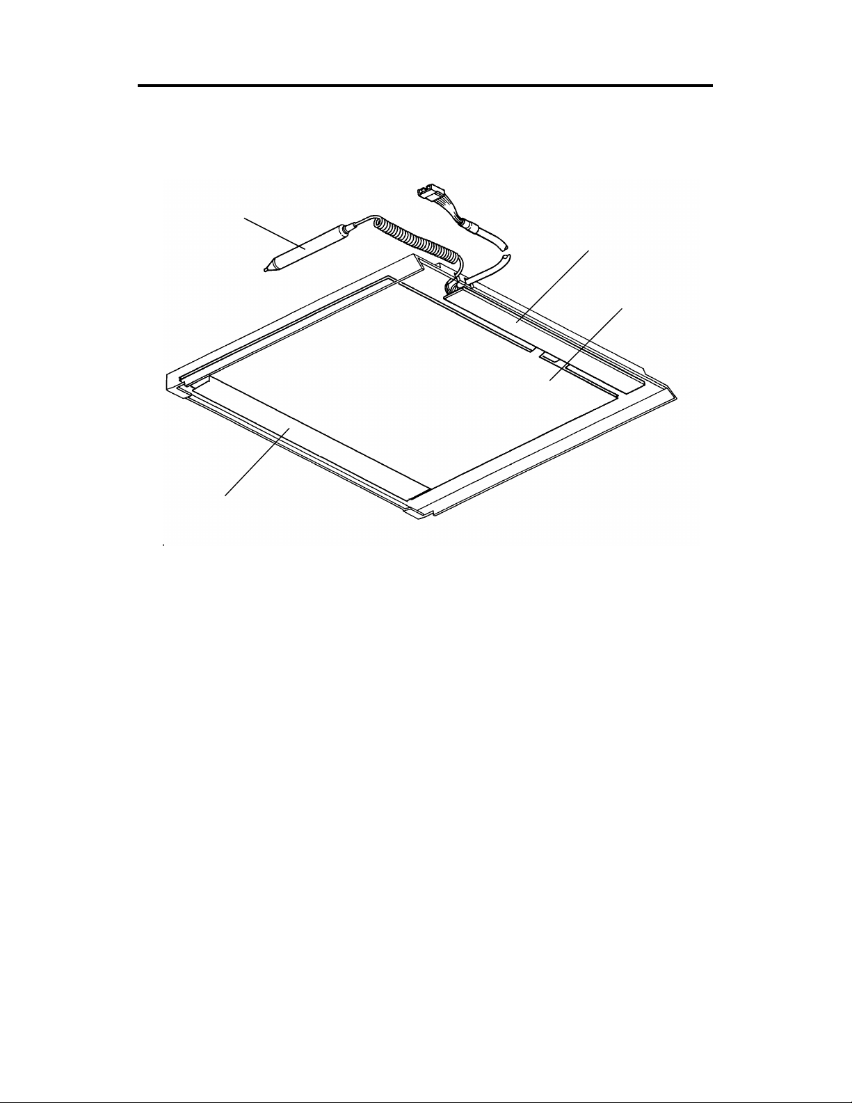
2. ELECTRICAL COMPONENT LAYOUT
2
1
3
4
1. Main PCB
2. Stylus
3. Positioning Sheet
4. Editor Operation Panel
2
Page 4
5 January 1995 ELECTRICAL COMPONENT DESCRIPTIONS
3. ELECTRICAL COMPONENT DESCRIPTIONS
PCBS
Main Controls the editor board and drives the positioning sheet
Interface
unit *
Others
Positioning
Sheet
Stylus Used to designate areas to be edited and to activate operation
Editor
Operation
Panel
Signals between the main fra me (op era tion panel) and the
editor are not directly connected , but are separated by the
photo-couplers on th e interface unit.
(This is only for European versions.) This is one of the
accessory parts.
Detects the position where the stylus presses
keys
Operation keys and indicators are located here
3
Page 5
BASIC OPERATION 5 January 1995
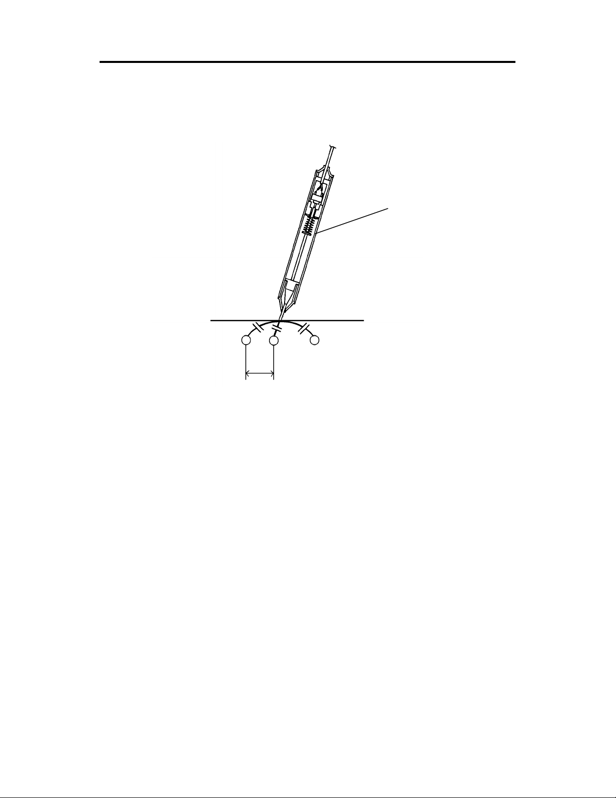
4. BASIC OPERATION
[A]
3 mm
There are electrode lines in the po sitio nin g she et align ed horizo nt ally and
vertically. Lines are spaced 3 mm apart. When part of the positioning sheet is
pressed with the stylus pen, stat ic co upling is generated between the stylu s
pen and the nearest electrode lines.
When the positioning sheet is p resse d with the st ylus pen [A ], the switch in
the stylus pen turns on and starts the detection of the coordinate point.
Therefore, the voltage corresponding to the coordinate point is sent to the
A/D converter. The volt ag e of the elect rode lines near the coordinate point
will be changed due to static coupling, and the coo rdin at e point is detected
by the voltage.
4
Page 6

5 January 1995 BLOCK DIAGRAM
5. BLOCK DIAGRAM
Positioning
Sheet
Editor Main PCB
CN2
A/D
Converter
CN3
CN3
CN4
CN4
Editor Operation Panel
Serial Output Request Error
Interface Unit for
European version
(DC–DC Conversion)
CN1
CN1
Serial Input Reset
CN1
CN1
+24 V
M
Copier
Operator
Panel
PCB
Front
IPU
Fan
The copier supplies +5 volts to the edit or. The signals between the editor and
the copier are as follows:
Pin No. Signal Name Function
1 GND —
2
Serial Input: TXD
(Copier to Editor)
Status signal of the co pie r.
3 GND —
4
5
Serial Output: RXD
(Editor to Copier)
Request
(Editor to Copier)
Error
6
(Editor to Copier)
Coordinate data and mode selection
data from the editor.
Request to receive data (Serial Input
Signal) from the copier.
Request to receive data (Serial Input
Signal) again from the copier when the
Serial Input Signal is in error condition.
7
Reset
(Copier to Editor)
Resets the editor.
8 Editor Connection Connects to GND on the editor boa rd.
9 / 10 +5v Source voltage.
For the European version, +24 V is supp lied to th e int er face unit which works
as a DC–DC converter.
5
Page 7

Revised on 15 July 1994
INSTALLATION (Machine Code: A988) 5 January 1995
6. INSTALLATION (Machine Code: A988)
6.1 SUMMARY
As the editor board is stand ard equ ipme nt for the model A105, fo r t he
installation refer to section 3.
This section only describes the installation for the editor bo ard for th e model
A092.
6.2 ACCESSORY CHECK
Check the quantity and cond itio n of the accessories in the box according to
the following list:
1. Installation Procedure......................................................................1
2. New Equipment Condition Report (17 and 27 versions) ................1
3. Harness Clamp................................................................................8
4. Harness Guard ............... .................................................................1
[–17 version only]
5. Envelope for NECR .........................................................................1
6. Interface Harness (with bracket) .....................................................1
7. Operating Instructions (English)......................................................1
[–25 and –27 version only]
8. Editor Panel Sheet
(English, German, French, Italian, and Sp anish)................. ...1 each
9. Interfa ce Unit ........................ ................................ ...........................1
10. Large Inte rface Harness........................ .......... .. .......... .......... .. ........1
11. Small Interface Harn ess..................................................................1
12. Operating Instructions ...................................................5 languages
6
Page 8

5 January 1995 INSTALLATION (Machine Code: A988)
6.3 INSTALLATION PROCEDURE
[European Version : –25 and –27]
[A]
[B]
[C]
[F]
[G]
[D]
[H]
1. Remove the platen cover [A].
2. Set the editor [B] onto the plat en cover bra cket.
3. Peel off the protective sheet [C] on the silver platen plate.
4. Remove all external strips of tape on the edit or board.
5. Remove the following ports:
• Operation panel [D] (3 screws)
• Top-right cover [E] (3 screws)
• Rear-upper cover [F] (2 screws)
• IPU cover [G] (11 screws)
• Front-right cover [H] (3 screws)
7
[E]
Page 9

INSTALLATION (Machine Code: A988) 5 January 1995
[A]
[C]
[B]
[D]
6. Remove the shielding cover [A] (2 screws).
7. Set the harness [B] as sho wn, and set the harness g ua rd [C] onto the
bracket together with the harness.
8. Install the interface unit [D] (2 screws). Use the 2 screws that were
removed in step 6.
8
Page 10

[B]
5 January 1995 INSTALLATION (Machine Code: A988)
CN3
[A]
[D]
[C]
[F]
9. Install 8 harness clamps [A] on the rig ht sid e of the scann er un it, as
shown.
10. Set the interface harne ss [B] in the clamps an d conne ct it to CN3 (6 pins)
on the operation pane l.
11. Connect the 2 pins conne ctor of the large interface harness [B] to the
small interface harness [C].
NOTE: From the three 2 pins connectors, use the one with th e lon gest
harness from the crossing point.
[E]
12. Set the small interface harness in two clamps [D], and route it beside the
front IPU inlet fan .
13. Disconnect the front IP U inlet fan harn ess an d con ne ct it to the sma ll
interface harness.
14. Reinstall the opera tion panel, the top-rig ht cover, the rear-upper cover,
and the front-right cover.
15. Connect the editor cable [E] onto the interface conne cto r (2 scre ws).
16. Install the appro priate language editor pa nel sh ee t [F] .
(Peel the back off the ed ito r sh ee t and stick the sheet to the edito r boa rd.)
9
Page 11

INSTALLATION (Machine Code: A988) 5 January 1995
[USA Version: –17 only]
[A]
[B]
[C]
[F]
[G]
[D]
1. Remove the platen cover [A].
2. Set the editor [B] onto the plat en cover bra cket.
3. Peel off the protective sheet [C] on the silver platen plate.
4. Remove all external strips of tape on the edit or board.
5. Remove the following parts:
• Operation panel [D] (3 screws)
• Top-right cover [E] (3 screws)
[E]
• Rear-upper cover [F] (2 screws)IPU cove r [G] (11 screws)
10
Page 12

5 January 1995 INSTALLATION (Machine Code: A988)
[A]
[C]
[D]
[B]
6. Remove the shielding cover [A] (2 screws).
7. Set the harness [B] as sho wn, and set the harness g ua rd [C] onto the
bracket together with the harness.
8. Install the harness bracket [D] (2 screws). Use the 2 screws that were
removed in step 6.
11
Page 13

INSTALLATION (Machine Code: A988) 5 January 1995
CN3
[B]
[A]
[C]
9. Install 8 harness clamps [A] on the rig ht sid e of the scann er un it, as
shown.
10. Set the interface harne ss [B] in the clamps an d conne ct it to CN3 (6 pins)
on the operation pane l.
11. Reinstall the opera tion panel, the IPU cover, the top -righ t cover, and the
rear-upper cover.
12. Connect the editor cable [C] onto th e int erf ace conn ect or (2 screws).
12
Page 14

5 January 1995 REPLACEMENT AND ADJUSTMENT
7. REPLACEMENT AND ADJUSTMENT
7.1 MAIN PCB AND EDITIO N OP ERATI O N PANE L
REPLACEMENT
[A]
[B]
[D]
1. Turn off the main switch of the copier.
2. Disconnect the interface cable (2 screws) and remove the edito r from th e
copier.
3. Remove the lower editor cover [A] (12 screws).
4. Remove the PCB cover [B] (4 screws).
5. Disconnect all connectors from the main PCB [C].
6. Remove the main PCB (6 screws).
7. Remove the editor operation pa nel [ D] (12 screws, 1 connector).
CAUTION: When replacing the main PCB, set the dip switc h as shown
in the decal on the harness. Se e the se rv ice table.
[C]
13
Page 15

SERVICE TABLE 5 January 1995
8. SERVICE TABLE
8.1 DIP SWITCH
The dip switch on the editor main board sho uld be set as shown in the decal
on the cable. If it is not the same, designated areas on copies can not be
processed properly.
DST-RO (A)
LOT:
(SW)
12345678
ON
OFF
The setting in the illust ration is an example.
NOTE: When the positioning sheet is replaced with a new one, set the
dip switch as shown in the decal on a new she et harness.
14
 Loading...