

Ricoh NC8115.015 Service Manual SF
SLIDE PROJECTOR UNIT
Model A092-17 A092-25 A092-27 A105-17 A105-27
A984-17 O X X O X
A984-27 X O O X X
A711-27XXXXO
O: The SPU can be connected to the copier.
X: The SPU cannot be con ne cted to the copier due to th e safety
standard.

5 January 1995 SPECIFICATIONS
1. SPECIFICATIONS
Acceptable Film Type: 35 mm positive and negative film, mounted film or
strip film (up to six frames per strip)
Warm-up Time: 0 sec.
Copy Speed: 4 cpm/81/2"x11", A4
1st Copy Time: 42 sec. (After pressing the start key)
Magnification Range: 50 to 400% ratios smaller than 50% are not
available when using the SPU
Focusing: Fixed focus
Projection Method: Slit (Horizontal)
Scanning Method: Moving Film
Projection Ratio: x 8.73
NOTE: For 115V/60HZ version, 93% is
automatically selected on the main fra me.
Effective Film Area: 21.5 x 33.0 mm (Full film size 24 x 36 mm)
Copy Image Size: 194 x 288 mm (Centering mode )
NOTE: Paper must be set lengthwise.
Power Source: 115 V/50, 60 Hz/ 10 A
220 ~ 240 V/50, 60 Hz/7 A
Power Consumption: 0.25 kw
Dimensions (W x D x H): Projector Unit:
12.5" x 18.5" x 11.4" (317 x 470 x 289 mm)
Mirror Unit:
1.8" x 10.1" x 1.8" (44 x 248 x 44 mm)
Weight: Projector Unit: Approx. 28.7 lbs (13.0 kg)
Mirror Unit: Approx. 1.1 lbs (0.5 kg)
1
COMPONENT LAYOUT 5 January 1995
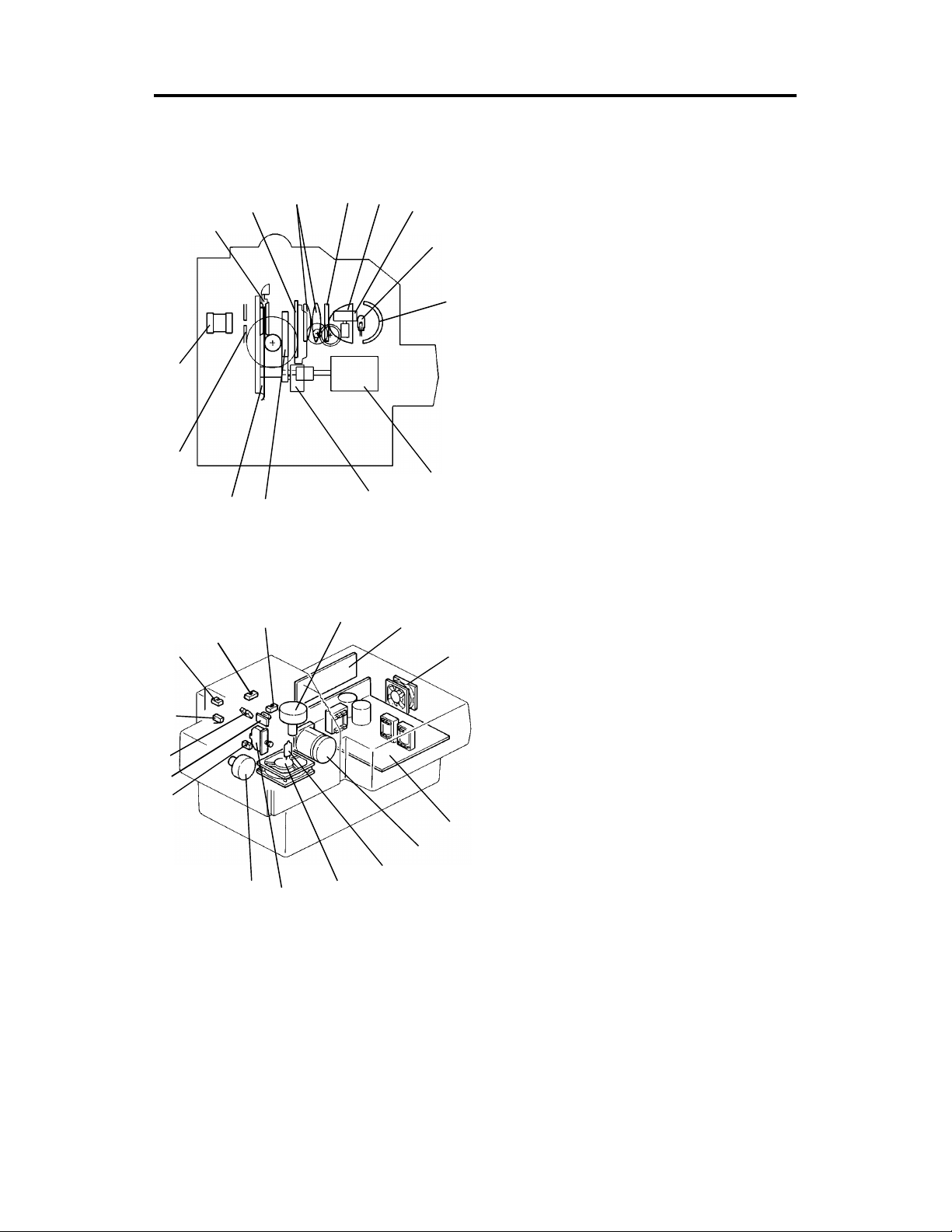
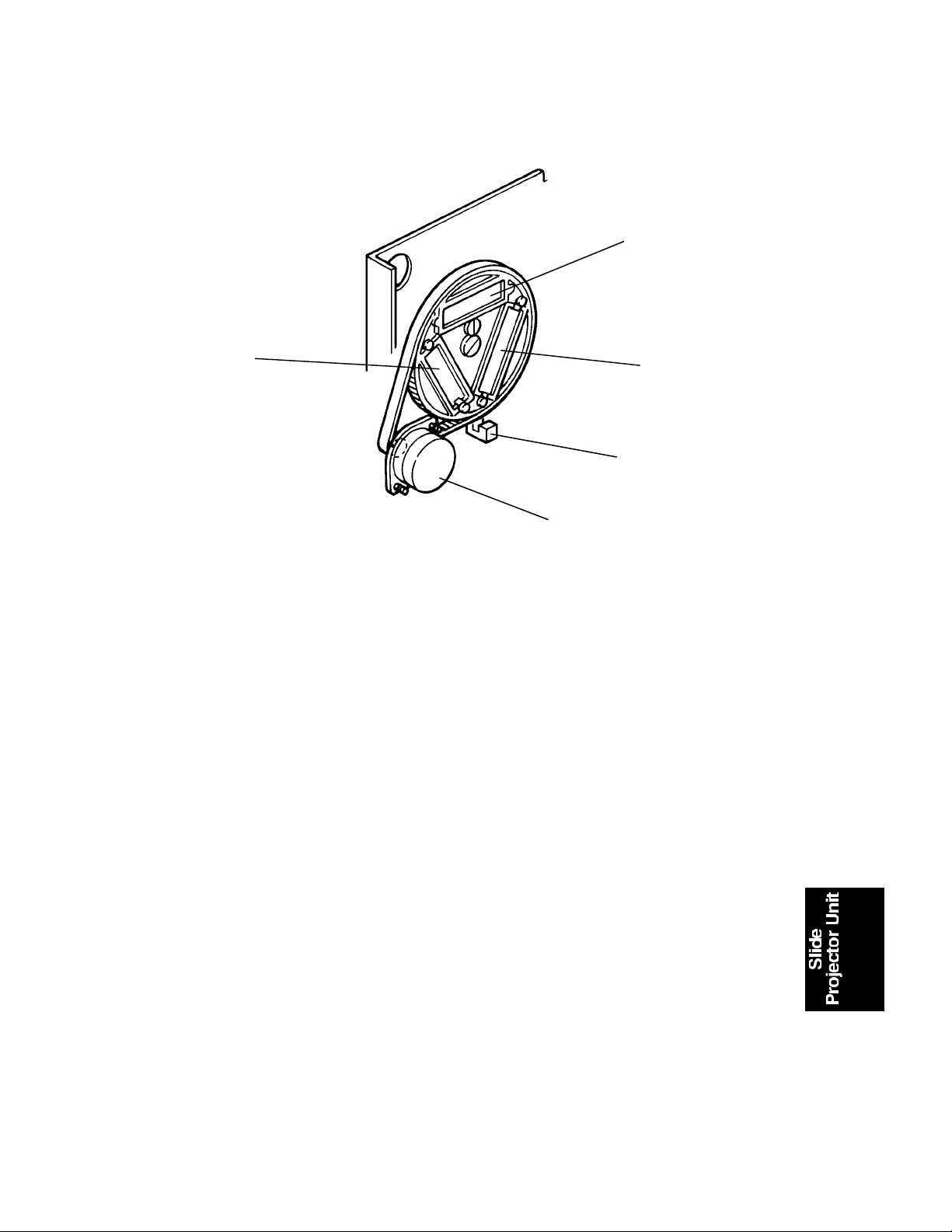
2. COMPONENT LAYOUT
Mechanical Components
Electrical Components
16
15
14
13
1
14
13
12
2
1
12
34
2
11
3
11
10
4
5
10
9
6
9
5
8
7
8
6
7
1. Film Holder
2. Light Compensation Filter
3. Condenser Lens
4. Heat Filter
5. Nonspherical Lens
6. Light Compensation Filter Motor
7. Halogen Lamp
8. Reflector
9. Film Scanning Motor
10. Color Compensation Filter Mot or
11. Color Compensation Filter
12. Film Scanning Belt
13. Diaphragm
14. Projection Lens
1. Film Scan H.P. Sensor
2. Mount Holder Set Se nsor
3. Light Compensation Filter H.P.
4. Light Compensation Filter Motor
5. Main PCB
6. PSU Outlet Fan
7. PSU (Power Supply Unit)
8. Film Scanning Motor
9. Halogen Lamp
10. Lamp Inlet Fan
11. Safety Switch
12. Color Compensation Filter Mot or
13. Color Compensation Filter H.P .
Sensor
14. Thermo Fuse
15. Lens Cover Sensor
16. Film Strip Holder Set Sensor
2
5 January 1995 ELECTRICAL COMPONENT DESCRIPTIONS
3. ELECTRICAL COMPONENT DESCRIPTIONS
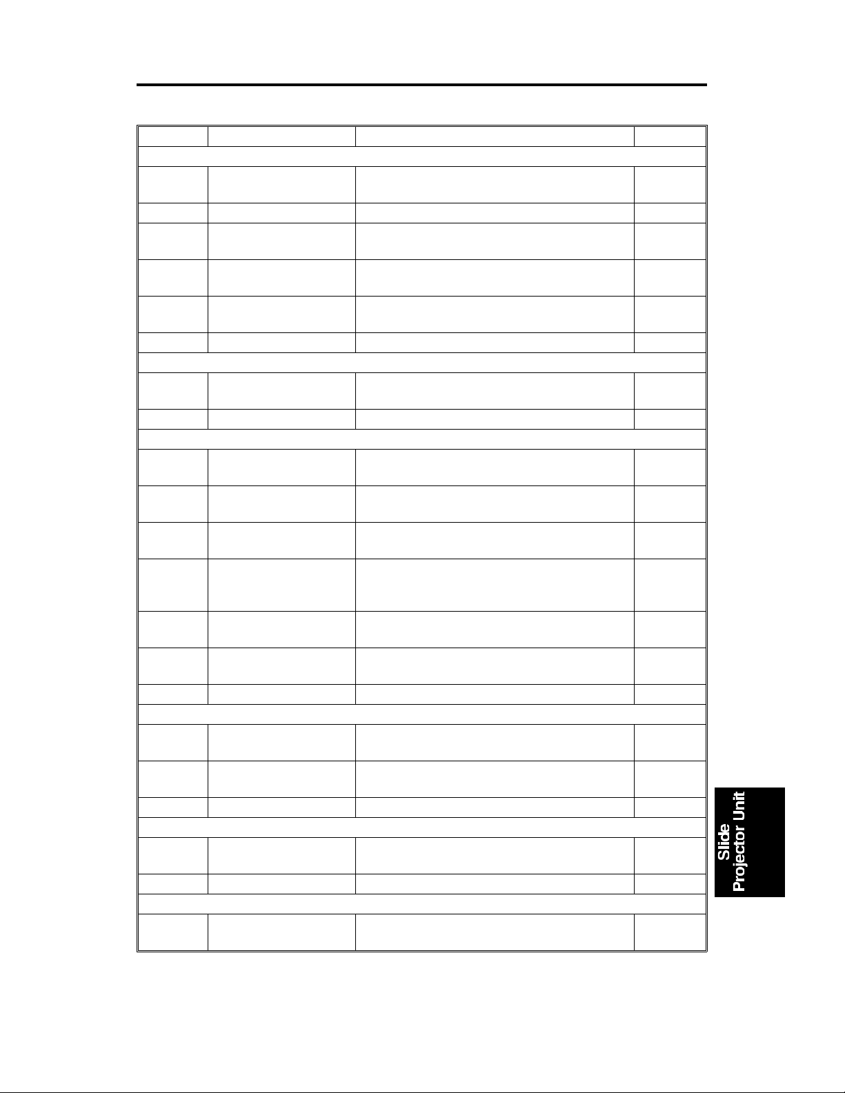
Symbol Name Function Location
Motors
M1
M2 PSU Outlet Fan Cools the PSU. 6
M3
M4
M5
Switches
SW1
Sensors
S1
S2
S3
S4
S5
S6
Light Compensation
Filter Motor
Film Scanning Motor Stepping Motor to move the film for
Lamp Inlet Fan Provides a flow of air to the halogen lamp to
Color Compensation
Filter Motor
Safety Switch Cuts DC 15 V current of the halogen lamp
Film Scan H.P. Sensor Notifies the CPU when the film is at the
Mount Holder Set
Sensor
Light Compensation
Filter H.P. Sensor
Color Compensation
Filter H.P. Sensor
Lens Cover Sensor Notifies the CPU whether the lens cover is
Film Strip Holder Set
Sensor
Stepping motor to move the light
compensation filter up and down.
scanning.
cool it.
Stepping Motor to turn the color
compensation filter.
when the lamp cover is opened.
home position.
Notifies the CPU when the mount holder is
set.
Notifies the CPU when the light
compensation filter is at the home position.
Notifies the CPU when the color
compensation filter H.P. sensor is at the
home position.
open or closed.
Notifies the CPU when the film strip holder
is set.
4
8
10
12
11
1
2
3
13
15
16
PCBs
PCB1
PCB2
Lamp
L1
Others
TF
Main PCB Controls the slide projector unit’s function
and communicates with the copier.
PSU Provides DC 15 V, 5 V, 12 V, and 24 V
current.
Halogen Lamp Supplies high intensity light to the film for
exposure.
Thermofuse Opens the 15 V line if the halogen lamp
overheats.
3
5
7
9
14
[D]
BASIC OPERATION 5 January 1995
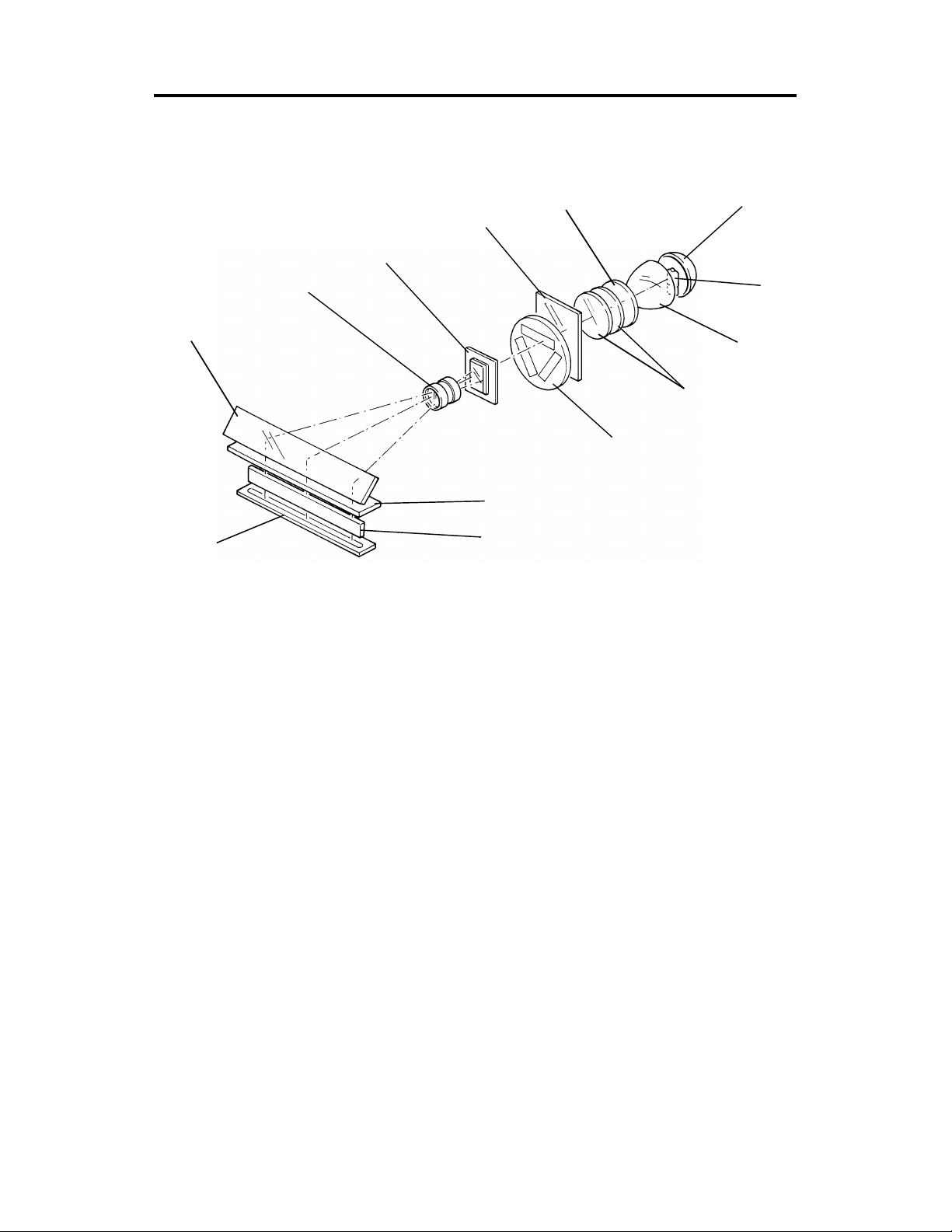
4. BASIC OPERATION
4.1 SUMMARY
[F]
[H]
[I]
[J]
[E]
[G]
[K]
[M]
[L]
[B]
[A]
[C]
The light of the haloge n lamp (150 W, 15 V) [A] is reflected by the reflector
[B] and it goes through the nonsphe rical len s [ C], the hea t filt er [D] , th e
condenser lens [E], the ligh t compensation filter [F], the color comp en sat ion
filter [G], and the film [H].
The heat filter cuts off heat from th e halog en lamp and pre vents the film from
deforming.
The light goes through the proje ctio n len s [I] , it is reflected 90° by the mirror
[J] and goes through the frost ed glass (up per layer: fresnel lens, lower layer:
diffused surface) [K] and the optical fib er arra y [L] to the full color CCD [M]
located on the copier’s scan ne r u nit .
NOTE: Film mounts with protective glass or filters can not be used. The se
are too thick to let the slide mount ho lde r clo se pro pe rly, resu ltin g in
a poorly focused image. In this case, take the film out of th e mount
with film protection glasses and set it to a normal mount for copying.
4
5 January 1995 BASIC OPERATION
4.2 FILM COLOR CORRECTION
[C]
[A]
[B]
[D]
[E]
The RGB Gamma characteristics are diff ere nt betwee n positive film and
negative film. The color compensation filters are used to compen sat e the
RGB Gamma characteristics of each film.
There are 3 windows on the disk. One is the filter [A] for positive film, one is
the filter [B] for negative film, the other is no filter [C] fo r detecting initial
condition, or for SPU focus adjustment (SP92).
Home position is detected by the color compensation filter H.P. senso r [D].
The color compensatio n filter is rotated by the colo r compensation filter moto r
[E].
5
BASIC OPERATION 5 January 1995
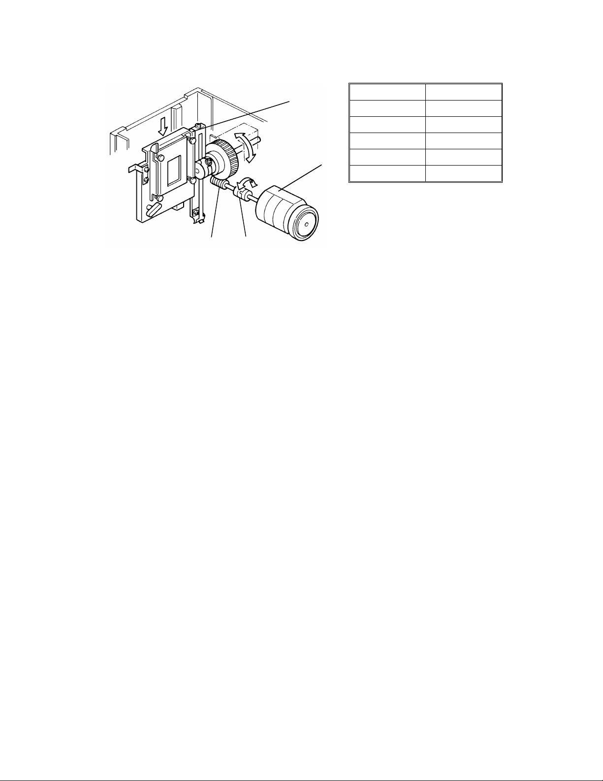
4.3 FILM SCANNING
[D]
[A]
Magnification Speed
50% 17.17 mm/sec
100% 8.59 mm/sec
200% 4.29 mm/sec
300% 2.86 mm/sec
400% 2.15 mm/sec
[B][C]
The film is scanned by being moved.
The scanner of the cop ier sta ys at 45 mm lef t of its h ome posit ion. The film is
moved down 50 mm (the length of film is 35 mm) at a specifie d speed . Se e
the table above.
The film scan motor [A] moves th e film up and down . The drive is tran sfe rred
through the coupling [B], worm gear [C], and film scan belt [D].
When 100% magnification is selected from the operation panel, the 35 mm
film image is actually enlarged 873% on the cop y.
For other magnification ratios, film scanning speed controls magnification in
the paper feeding direction, while image processing controls magnification in
the main scan direction.
Concerning leading edge regist ration and side to side registration, the y will
be easily changed between each copy or each orig inal due to its reproduction
ration (1 : 8.73). If the scann ing is delaye d 0.5mm, the image is shifted about
4 mm to the trailing edge.
For 115V/60Hz models, 93% reproduction ratio is automatically selected to
accommodate 81/2" x 11" paper. 11" (279 mm) is too short to sele ct 100%.
The Effective film area is 21.5 x 33 mm.
• Copy image on A4 lengthwise paper (210 x 297 mm):
21.5 x 8.73 = 187.7 mm
33 x 8.73 = 288.1 mm
• Copy image on 81/2" x 11" lengthwise paper (216 x 279):
187.7 x 0.93 = 174.6 mm
288.1 x 0.93 = 268.0 mm
6
5 January 1995 BASIC OPERATION
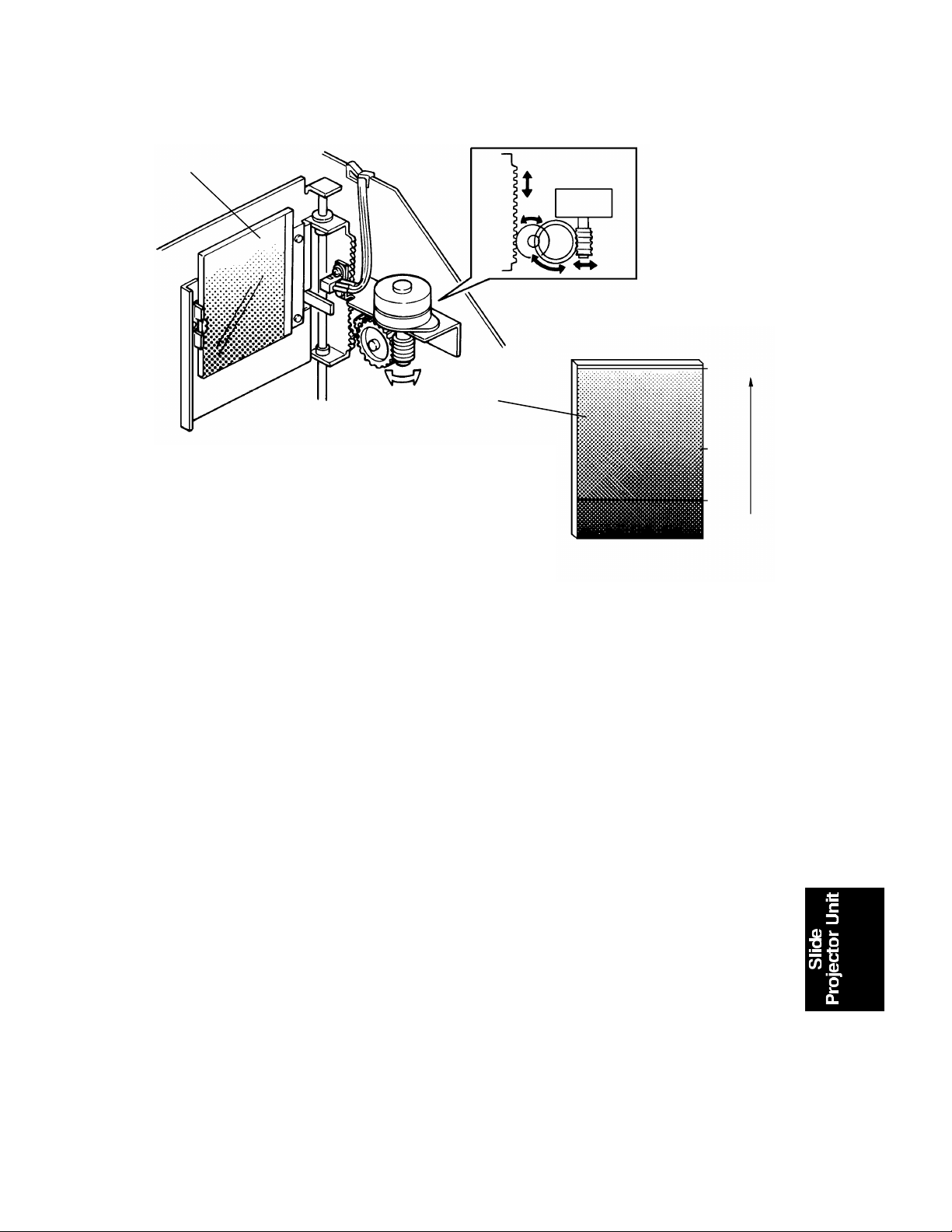
4.4 SHADING
[A]
100%
[A]
50%
Light
30%
0%
Dark
Shading corrects the following variations of the video data.
• V aria tions in sensitivity between bits of the CCD (arising from
production processes).
• V ariations in characteristics of th e colo r co mpe nsa tion filter,
light compensation filte r, mirror un it, lense s, an d op tica l fiber
array unit in the copier.
• L oss of brightness at both front and rear ends of the exposure
on the CCD.
• V aria tions in characteristics of the negative film
Negative film:
Color negative film comes in many kinds. A negative is a photo image laid on
a transparent strip of pla stic (calle d a ba se). All emulsio ns are to some extent
similar, but most bases are diffe ren t. Th e bases will a ff ect color ba lan ce, but
the effect is corrected by the shading function.
Positive films:
Positive films have more or less identical bases. So , the film base does no t
affect shading.
7

BASIC OPERATION 5 January 1995
Before scanning the original film, the shading function must be performed.
Set the base film (negative film mode) or no film (positive film mod e) in th e
film holder and press the shading key. The film holder goes down and stops
in position for scannin g of its the center area. The machine reads it as it
would a white reference board.
In this case, the light compensa tio n filt er [A] goes down to expose the 30%
density area of its filter. (100% : Clear, 0%: Pure black) See the previous
page. The maximum data is compared with the data in of the Video
Processing Board. If th e da ta is lower (darker) than the data in this bo ard , the
light compensatio n filter will be moved to expose the lighter area. If the dat a
is higher (brighter) than the data in the board, the filte r will be moved to
expose the darker area. Th e ap pro priate color compensation filter is selected.
For the next step, the machine scans 16 lines while the film is going up. The
Video Processing Board avera ges t he 16 line s pixel by pixe l fo r one main
scan, and the calculate d da ta is stored in that board. This is the wh ite wave
form data, which is used to correct the distortion of the video signal. Se e
page 2-29 of the PDC-1E service manual.
NOTE: If the mirror unit on the exp osu re gla ss suffers any vibration after
shading, vertical lines will appear on the copy image due to impro per
shading data of each picture eleme nt of the CCD.
To prevent or minimize these lines, do the follo wing ;
1) Fix the machine on the floor using four leveling shoes.
2) Advise the operator to take care against vibration s to th e copier
after shading.
3) Reset the mirror unit and perform shad ing again.
However, in negative mode, vertical lines in low tone areas are
normal, and it is not possible to eliminate th em comp letely. In
positive mode, these lines will be reproduced in high tone areas on
the copy.
8

Film movement
5 January 1995 BASIC OPERATION
4.5 AUTO IMAGE DENSITY
Trailing edge
35 mm
Leading edge
: Scanning area
: Pre-scanning area
After shading, the origin al film [A ] is pre-scanned to detect the brightest poin t.
The pre-scanning area is smaller than the scann ing area .
Exposure area: 35 mm x 24.0 mm
Pre-scanning area: 31 mm x 20.2 mm
Scanning area: 33 mm x 22.2 mm
Based on the data from t he brigh te st po int, the light compensat ion filter
position is re-adjusted. This prescanning is performed just be fo re cop ying.
9
[A]
BASIC OPERATION 5 January 1995
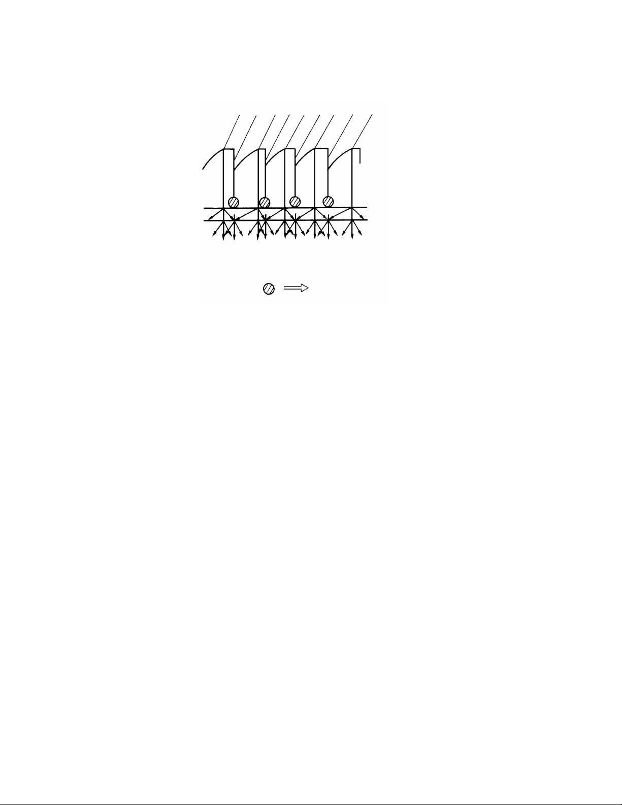
4.6 MIRROR UNIT
Light
[B]
Shadow
The mirror unit consists of the mirror, and th e frosted glass (upper layer:
fresnel lens, lower layer: diff use d surf ace). See the summary.
The fresnel lens [A] chang es th e ref lect ed image light path to para llel, and the
frosted glass [B] clears the shad ow fro m t he fresn el lens.
The image is formed on the frosted glass, which is in contact with the cop ier’s
exposure glass. The image is t he n see n by th e op tical fiber array.
10
 Loading...