

Page 1
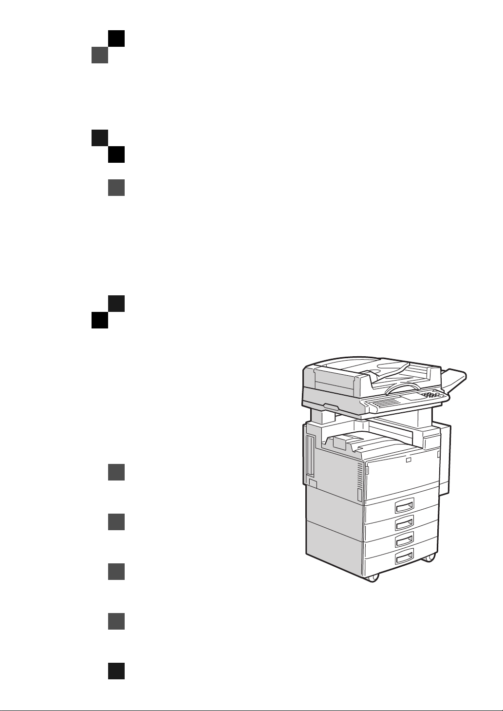
SCANNER Option Type
450
OPERATING INSTRUCTIONS
SCANNER REFERENCE(option)
ND0A0101
Read this manual carefully before you use this product and keep it handy for future
reference.
For safety, please follow the instructions in this manual.
Page 2

SCANNER Option Type 450 OPERATING INSTRUCTIONS
Printed in Japan
UE USA A695-8510
EE GB
Page 3

Introduction
This manual contains detailed instructions on the operation and maintenance of this machine. To get
maximum versatil ity from this ma chine all opera tors sho uld careful ly read an d follow the ins tructi ons in
this manual.Please keep this manual in a handy place near the machine.
Please read the Safety Information in the “Copy Reference” before using this machine. It contains important information related to USER SAFETY and PREVENTING EQUIPMENT PROBLEMS.
Important
Parts of this manual are subject to change without prior notice. In no event will the company be liable
for direct, indirect, special, incidental, or consequential damages as a result of handling or operating
the machine.
Page 4

Note to users in the United States of America
This equipment has been tested and found to comply with the limits for a Class B digital device, pursuant
to Part 15 of the FCC Rules. These limits are designed to provide reasonable protection against harmful
interference in a residential installation. This equipment generates, uses and can radiate radio frequency
energy and, if not installed and used in accordance with the instructions, may cause harmful interference
to radio communications. Ho wever, there is no guarantee that inter f ere nce will not occur in a particular
installation. If this equipment does cause harmful interference to radio or television reception, which can
be determined by turning the equipment off and on, the user is encouraged to try to correct the interference by one more of the following measures:
Reorient or relocate the receiving antenna.
Increase the separation between the equipment and receiver.
Connect the equipment in to an outlet on a circuit differe nt f ro m t hat t o w hi ch the receiver is
connected.
Consult the dealer or an experie nced radio /TV technician for help.
Warning:
Changes or modifications not expressly approved by the party responsible for compliance could void the
user's authority to operate the equipment.
Caution
Properly shielded and grounded cables and connectors must be used for connections to host computer
(and/or peripheral) in order to meet FCC emission limits.
Declaration of conformity
Product Name: Scanner Option
Model Number: Type 450
Responsible party: Ricoh Co rpo ration
Address: 5 Dedrick Place, West Caldwell, NJ 07006
Telephone number: 973-882-2 000
This device complies with part 15 of FC C Rules.
Operation is subject to the following two conditions:
1. This device may not cause harmful interfe re nce, and
2. this device must accept any interference received,
including interference that may cause undesired operation.
Note to users in Canada
This Class B digital apparatus meets all requirements of the Canadian Interference-Causing Equipment
Regulations.
Remarque concernant les utilisateurs au Canada
Cet appareil numérique de la classe B r especte toutes les exigences du Règlement sur le matériel
brouilleur du Canada.
In accordance with ISO S tandard 7001, this mach ine uses the following symbols for the main power
switch:
aaaa
means POWER ON.
bbbb
means POWER OFF.
Declaration of Conformity
“The Product complies with the requir ements of the EMC Directive 89/336/EE C and the Low Voltage
Directive 73/23/EEC.”
Page 5

How to Read this Manual
Symbols
In this manual, the following symbols are used:
Important
If this instruction is not followed, paper might be misfed, originals might be
damaged, or data might be lost. Be sure to read this.
Preparation
This symbol indicates the prior knowledge or preparations required before operating.
Note
This symbol indicates precautions for operation, or actions to take after misoperation.
Limitation
This symbol indicates numerical limits, functions that cannot be used together,
or conditions in which a particular function cannot be used.
Reference
This symbol indicates a reference.
[ ]
Keys that appear on the machine's panel display.
Keys and buttons that appear on the computer's display.
{ }
Keys built into the machine's operation panel.
i
Page 6

TABLE OF CONTENTS
1.Preparation
The Scanner Interface............................................................................... 2
Requirements............................................................................................. 3
Connecting to the Computer.................................................................... 4
Making the connection .................................................................................. 4
Setting the SCSI ID....................................................................................... 4
2.Setting Originals
Setting Originals on the Exposure Glass................................................ 8
Setting Originals In The Document Feeder (ADF)................................ 10
1-sided Scanning ........................................................................................ 11
2-sided Scanning ........................................................................................ 12
3.Appendices
Troubleshooting...................................................................................... 15
Status Messages.................... ..... .... ..... ............................ ..... .... ..... ......... 16
Specification............................................................................................ 18
ii
Page 7

1. Preparation
This chapter provides important information on the requirements for using your
machine installed with the scanner unit. This chapter also provides information
on setting up your machine as a scanner.
1
Page 8
1
Preparation
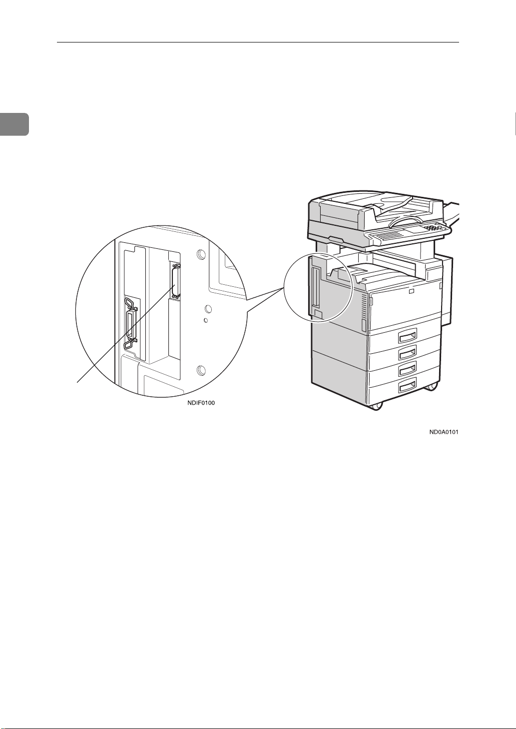
The Scanner Interface
The scanner unit is installed in the left side of your machine (as shown in the illustrations) The scanner unit connects to a computer through a 50–pin half –
pitch (pin type) SCSI connector.
1
1. Scanner unit interface 50–pin half-pitch (pin type) SCSI connector
Optional equipment is installed in this illustration.
2
Page 9

Requirements
Requirements
In order to use your machine as a scanner, the following hardware/software is
required in the computer that will be connected to the scanner. Make sure that
all the necessary hardware and software is in place before attempting to scan.
❖❖❖❖
CPU
Intel®Pentium 75MHz or better.
❖❖❖❖
OS
Windows®95/98/3.11, Windows NT®3.51, or NT®4.0.
❖❖❖❖
Memory
16MB or more (for scanning).
48MB recommended.
❖❖❖❖
Hard disk
100MB or more of free disk space recommended. Approximately 16MB of
space is required to save one page of an A4 monochrome image scanned at
400dpi with a 256–value gray scale.
1
❖❖❖❖
SCSI board
Use a SCSI board recommended by the local dealer. The system may not operate properly with some SCSI boards.
❖❖❖❖
SCSI interface cable
Use a SCSI interface cable recommended by the local dealer. The type of SCSI
interface cable required depends on the SCSI board that is installed in the
computer.
3
Page 10

Preparation
Connecting to the Computer
The scanner unit uses SCSI-2 interface to connect to the computer.
1
Important
Do not daisy chain other SCSI devices with the scanner.
❒
The scanner might not operate properly with some SCSI boards (installed in
❒
the computer).
Since the scanner unit has a built-in terminator, no terminator needs to be
❒
connected to the scanner. A terminator is only required at the other end of the
connection (i.e.,on the SCSI board in the personal computer).
Making the connection
A Turn the computer off.
B Make sure that none of the other functions are in use, and then turn off the
main power switch of the machine.
C Connect the 50–pin half-pitch (pin type) end of the SCSI interface cable to
the SCSI connector on the machine.
D Connect the other end of the SCSI interface cable to the computer.
Setting the SCSI ID
The SCSI ID for the scanner is initially set to “4”. Normally, there is no need to
change this ID. If it is necessary to change this ID, follow the procedure bellow.
A Turn the computer off.
B Turn on your machine, and wait until ”Ready” appears on the panel dis-
play of the machine.
4
Page 11

Connecting to the Computer
C Press the
The User Tools Main Menu appears.
D Enter
The System Settings appears.
E Press the
ter its number with the
The “Scanner SCSI-ID”appears.
F Use
<<<<>>>>
G Press the
User Tools/Counter
{{{{
with the
1
}}}}
{{{{
↓↓↓↓
Next
{{{{
keys to highlight the SCSI ID that is to be set.
key.
]
[
OK
}}}}
or
Number
{{{{
↑↑↑↑
Prev.
{{{{
key of the machine.
}}}}
keys.
}}}}
keys until ”Scanner SCSI-ID” appears, and En-
}}}}
Number
{{{{
key.
}}}}
H Turn off the main power switch of the machine, and then back on again.
1
I Turn the computer back on.
5
Page 12

1
Preparation
6
Page 13

2. Setting Originals
This chapter explains how to set the originals in the machine when using it as a
scanner. The originals can be set either on the exposure glass or in the document
feeder (ADF).
7
Page 14

Setting Originals
Setting Originals on the Exposure Glass
The exposure glass can be used when scanning originals that cannot be set in the
document feeder (ADF), such as books or originals that have been pasted together. For convenience, these types of originals will be referred to as “book originals.” Follow these steps to set originals on the exposure glass.
2
A Lift the platen cover or the document feeder(ADF), and place the original
face down on the exposure glass.
1. Reference mark
Important
Set the original after correction fluid and ink has completely dried. Not
❒
taking this precaution could mark the exposure glass and cause marks to
be copied.
Note
Set the original in the direction shown in the illustration. The direction of
❒
resulting scan is as follows.
1. Reference mark
8
Page 15

Setting Originals on the Exposure Glass
B Lower the platen cover or the document feeder(ADF).
2
9
Page 16

2
Setting Originals
Setting Originals In The Document Feeder
(ADF)
You can set several pages of originals in the document feeder (ADF) at a time.
Only originals that consist of separate sheets of paper can be set in the document
feeder (ADF); for convenience, such originals will be called “sheet originals.” It
is possible to copy not only one side but both sides of originals that are set in the
document feeder (ADF).
❖❖❖❖
Non-recommended originals for the document feeder
Setting the following originals in the document feeder might cause paper misfeeds or damage to the originals. Set these originals on the exposure glass.
• Originals other than those specified in the copy reference
• Stapled or clipped originals
• Perforated or torn originals
• Curled, folded, or creased originals
• Pasted originals
• Originals with any kind of coating, such as thermal fax paper, art paper,
aluminum foil, carbon paper, or conductive paper
• Originals with indexes, tags, or other projecting parts
• Sticky originals such as translucent paper
• Thin original that has low stiffness
• Originals of inappropriate weight in the copy reference
• Bound originals such as books
• Transparent originals such as OHP transparencies or translucent paper
❖❖❖❖
Setting Originals In The Document Feeder
• Do not stack originals above the limit mark
• When copying thin originals (41–52g/m
set to Thin Paper mode, or set your originals on the exposure glass to avoid
damage due to a multi-sheet feed (if several sheets are fed together at the
same time).
See”Thin Paper mode”in the copy reference.
• The original might become dirty if it is written with a pencil or similar
tools.
• For 1–sided originals, you can select the ADF tray or the ADF external tray
as an output tray
See”22.ADF Orig.Ejection”in the System Settings.
2
11–14lb), select
[
DF Setting
and
]
10
• Scanning speed might be a little reduced if the ADF tray is selected as an
output tray. (for 1–sided originals)
Page 17

Setting Originals In The Document Feeder (ADF)
1-sided Scanning
A Set the originals into the document feeder (ADF) with the side to be
scanned face up.
Note
The sheet of the original should be ordered in the preferred page sequence.
❒
2
1
2
3
To avoid a multi-sheet feed (in which the ADF feeds through more than
❒
one sheet at a time), fan the pages of the original before setting them in the
document feeder (ADF).
11
Page 18

2
Setting Originals
Set the original with the same direction as shown in the illustration. The di-
❒
rection of the resulting scan is as follows.
B Adjust the guide on the document feeder (ADF) to the original size.
2-sided Scanning
A set the originals in the document feeder (ADF) with the side to be scanned
first (the front side of the original) face up.
12
Page 19

Setting Originals In The Document Feeder (ADF)
Note
The sheets of the original should be ordered in the preferred page se-
❒
quence.
To avoid a multi-sheet feed (in which the ADF feeds through more than
❒
one sheet at a time), fan the pages of the original before setting them in the
document feeder (ADF).
Set the original with the same direction of the front side as shown in the
❒
illustration. The direction of the resulting scan of the reverse side will be
upside down, as shown below.
2
R B
B Adjust the guide on the document feeder (ADF) to the original size.
13
Page 20

2
Setting Originals
14
Page 21

3. Appendices
Troubleshooting
This section explains the possible causes and the action when the scanner does
not scan an image in the expected manner.
Status Cause Action
The scanned image is dirty. The exposure glass or the
platen cover is dirty.
The scanned image is distorted or out of position
The scanned image is upside down.
The original image cannot
be scanned.
The original is moved
while it is being scanned.
The original is not pressed
flat against the exposure
glass.
The original was placed
upside down.
The original was placed
with the front and the back
reversed.
Clean the exposure glass or
the platen cover.
Do not move the original
while it is being scanned.
Make sure that the original
is pressed flat against the
exposure glass.
set the original in the correct direction.
Reference
P.8
“Setting Originals on
the Exposure Glass”
P.10
“Setting Originals In
The Document Feeder
(ADF)”
When setting originals on
the exposure glass, place
the side to be scanned face
down; when setting originals in the document feeder (ADF), place the side to
be scanned face up.
The image density has
changed in the middle of
the scan.
Some types of originals
may cause the density to
change in the middle of a
scan.
Reference
P.8
“Setting Originals on
the Exposure Glass”
P.10
“Setting Originals In
The Document Feeder
(ADF)”
Set the Erase Background
to "off" and scan the original again.
15
Page 22

Appendices
Status Messages
The following table shows the status messages and the machine's conditions
when used as a scanner.
Status Messages Descriptions
3
While standing by Scanner on Line
Set original on the platen
glass (ADF) and set scanning mode from computer.
While scanning an original placed on the exposure glass.
While transferring the
data scanned from the
exposure glass to a computer.
During continuous
scanning (while scanning originals placed on
the document feeder
(ADF).
While transferring the
scanned data to a computer.
Scanner on Line
Scanning- Please wait
Scanner on Line
Scanning- Please wait
• Input from all of the function key is accepted.
• Input from the
key is accepted
• Interrupt requests from
other functions are accepted.
• The System Reset function works.
• Input is not accepted
from any of the function
keys.
• Input from the
key is not accepted
• Interrupt requests from
other functions are not accepted.
• The System Reset function does not work.
• Input is not accepted
from any of the function
keys.
• Input from the
key is not accepted
• Interrupt requests from
other functions are not accepted.
• The System Reset function does not work.
Interrupt
{
Interrupt
{
Interrupt
{
}
}
}
16
Page 23

Status Messages Descriptions
Status Messages
While saving scanned
data to a hard disk in a
computer.
Note
The scanner unit operates under incremental scanning control. Under “incre-
❒
Scanner on Line
Scanning- Please wait
• Input from all of the function keys is accepted.
• Input from the
key is not accepted
• Interrupt requests from
other functions are not accepted.
• The System Reset function does not work.
Interrupt
{
mental scanning control”, the scanned data is sent to the host (the attached
computer) when the scanner unit's buffer becomes full. As a result, the scanner may appear to stop operating while it is in the process of scanning an original. Refer to the panel display (listed above) you will find whether or not the
scanner is operating. Once the scanner has finished scanning, the display returns to the standby screen.
}
3
17
Page 24

3
Appendices
Specification
Scanning method Stationary one-dimensional solid scanning system (incre-
mental scanning control)
Image sensor type CCD image sensor
Original types sheet, book, object
Interface SCSI-2 interface
Maximum original size A3L,11"×17"
Resolution 400dpi
• For monochrome 256–value (gray scale) scanning, a resolution of 100 to 400dpi can be specified (in units of
4dpi).
• For monochrome or monochrome (half tone) scanning, a
resolution of 100 to 1600dpi can be specified (in units of
4dpi).
L
18 UE USA EE GB A000
 Loading...