

Ricoh D245, D247, D246, MP 2014AD, MP 2014 Service Manual
...
D245/D246/D247
SERVICE MANUAL

It is the reader' s resp onsibili ty when discus sing th e info rmation c ontained
within this document to maintain a level of confidentiality that is in the best
interest of Ricoh Americas Corporation and its member companies.
NO PART OF THIS DOCUMENT MAY BE REPRODUCED IN ANY
FASHION AND DISTRIBUTED WITHOUT THE PRIOR
PERMISSION OF RICOH AMERICAS CORPORATION.
All product names, domain names or product illustrations, including
desktop images, used in this document are trademarks, registered
trademarks or the property of their respective companies.
They are us ed thr ou gh out this book in an i nf orm a ti on al o r editorial fas hi o n
only and for the benefit of such companies. No such use, or the use of
any trad e name, or web si te is int ended to convey e ndorsement or other
affiliation with Ricoh products.
2015 RICOH Americas Corporation. All rights reserved.

The Service Manual contains information
regarding service techniques, procedures,
processes and spare parts of office equipment
distributed by Ricoh Americas Corporation.
Users of this manual should be either service
trained or certi fied by s uccessfully com pleting a
Ricoh Technic al Trai ning Progr am .
Untrained and uncertified users utilizing
information contained in this service manual to
repair or modify Ricoh equipment risk personal
injury, damage to property or loss of warranty
protection.
Ricoh Americas Corporation
WARNING

LEGEND
PRODUCT
CODE
COMPANY
LANIER RICOH
D245 MP 2014 MP 2014
D246 MP 2014D MP 2014D
D247 MP 2014AD MP 2014AD
DOCUMENTATION HI S TORY
REV. NO.
DATE
COMMENTS
*
08/2015
Original Printing

SM i D245/D246/D247
D245/D246/D247
TABLE OF CONTENTS
1. PRODUCT INFORMATION ........................................................... 1-1
1.1 PRODUCT OVERVIEW ................................................................................................. 1-1
1.1.1 CO MPONENT LAYOUT ...................................................................................... 1-1
1.1.2 PAPER PATH ....................................................................................................... 1-2
1.1.3 DRIVE LAYOUT .................................................................................................. 1-3
1.1.4 PARTS LAYOUT .................................................................................................. 1-4
ADF unit (D247 only) ............................................................................................... 1-4
Scanner Unit ............................................................................................................ 1-5
Paper Feed Unit ...................................................................................................... 1-6
Laser Unit/ PCDU/ Fusing Unit ............................................................................... 1-7
By-pass Unit ............................................................................................................ 1-8
Paper Exit/ Reverse/ Duplex Unit ............................................................................ 1-9
Drive Unit ............................................................................................................... 1-10
Electrical Component ............................................................................................ 1-11
1.2 MACHINE CODES AND PERIPHERAL S CONFIGURATION .................................... 1-12
1.2.1 SYSTEM CONFIGURATION AND OPTIONS ................................................... 1-12
1.3 GUIDANCE FOR THOSE WHO ARE FAMILIAR WITH THE PREDECESSOR PRODUCT
1-13
1.3.1 DIFFERENCES BETWEEN SIMILAR MODELS .............................................. 1-13
D160/D161 vs. D245/D246/D247.......................................................................... 1-13
2. INSTALLATION ............................................................................. 2-1
2.1 INSTALLATION REQUIREMENTS ................................................................................ 2-1
2.1.1 ENVIRONMENT .................................................................................................. 2-1
2.1.2 MACHINE LEVEL ................................................................................................ 2-2
2.1.3 MINIMUM SPACE REQUIREMENTS ................................................................. 2-2
2.1.4 MA CHINE DI MENS IONS .................................................................................... 2-3
2.1.5 P OWER REQUIREME NTS ................................................................................. 2-3
2.2 COPIER INSTALLATION ............................................................................................... 2-4
2.2.1 ACCESSORY CHECK ........................................................................................ 2-4
2.2.2 I NSTALLATION PROCE DURE ........................................................................... 2-5
2.2.3 CHECK IMAGE QUALITY / SETTINGS............................................................ 2-11
Checking the copy image with the test chart ........................................................ 2-11
2.2.4 MOV ING THE MACHINE .................................................................................. 2-11
2.2.5 T RANSPORTING THE MACHINE .................................................................... 2-11

SM ii D245/D246/D247
2.3 PAPER FEED UNIT PB2020 ....................................................................................... 2-12
2.3.1 ACCESSORY CHECK ...................................................................................... 2-12
2.3.2 INSTALLATION PROCEDURE ......................................................................... 2-12
For Installing Single Paper Feed Unit ................................................................... 2-13
For Installing Double Paper Feed Units ................................................................ 2-16
2.4 BY-PASS TRAY COVER TYPE M16 ........................................................................... 2-20
2.4.1 COMPONENT CHE CK ..................................................................................... 2-20
2.4.2 INSTALLING THE EXPANSION COMPONENT ............................................... 2-21
2.5 DDST UNIT TYPE M16 ................................................................................................ 2-25
2.5.1 COMPONENT CHE CK ..................................................................................... 2-25
2.5.2 INSTALLING THE EXPANSION COMPONENT ............................................... 2-25
2.6 OPERATION GUIDANCE FOR USERS ...................................................................... 2-27
3. PREVENTIVE MAINTENANCE..................................................... 3-1
3.1 PREVENTIVE MAINTENANCE T ABLES ...................................................................... 3-1
3.2 PM PARTS SETTINGS .................................................................................................. 3-1
3.2.1 PM PARTS REPLACEMENT PROCEDURE ...................................................... 3-1
3.2.2 AFTER INSTALLING THE NEW PM PARTS ...................................................... 3-1
3.2.3 OPERATION CHECK .......................................................................................... 3-1
4. REPLACEMENT AND ADJUSTMENT ......................................... 4-1
4.1 BEFOREHAND .............................................................................................................. 4-1
4.2 SPECIAL TOOLS AND LUBRICANTS .......................................................................... 4-1
4.2.1 SPECIAL TOOLS ................................................................................................ 4-1
4.3 EXTERIOR COVERS..................................................................................................... 4-2
4.3.1 FRONT DOOR .................................................................................................... 4-2
4.3.2 PAPER TRAY 1 ................................................................................................... 4-2
4.3.3 FRONT LEFT COVER......................................................................................... 4-2
4.3.4 FRONT RIGHT COVER ...................................................................................... 4-3
4.3.5 LEFT COVER ...................................................................................................... 4-5
4.3.6 RIGHT REAR CO VER ........................................................................................ 4-5
4.3.7 RIGHT UPPER COVER ...................................................................................... 4-5
4.3.8 PAPER EXIT TRAY ............................................................................................. 4-6
4.3.9 REAR COVER ..................................................................................................... 4-6
4.3.10 RIGHT DOOR ...................................................................................................... 4-6
Reinstall the right door ............................................................................................ 4-8
4.4 ADF UNIT ....................................................................................................................... 4-9
4.4.1 ADF UNIT ............................................................................................................ 4-9
4.4.2 PLATEN COVER SENSOR............................................................................... 4-10
4.4.3 ADF FRONT COVER ........................................................................................ 4-10

SM iii D245/D246/D247
4.4.4 ADF REAR COVER .......................................................................................... 4-11
4.4.5 DOCUMENT TABLE .......................................................................................... 4-12
4.4.6 PICK-UP ROLLER............................................................................................. 4-13
4.4.7 SEPARATION PAD ............................................................................................ 4-14
4.4.8 ADF COVER SENSOR/ORIGINAL SET SENSOR .......................................... 4-15
4.4.9 ADF PICK-UP SOLENOID ................................................................................ 4-15
4.4.10 ADF INVERTER SOLENOID ............................................................................ 4-16
4.4.11 ADF FEED ROLLER ......................................................................................... 4-17
4.4.12 ADF MOTOR ..................................................................................................... 4-19
4.4.13 ADF REGISTRATION SENSOR ....................................................................... 4-19
4.5 OPERATION PANEL .................................................................................................... 4-20
4.5.1 OPU BOARD ..................................................................................................... 4-20
4.6 SCANNER UNIT .......................................................................................................... 4-21
4.6.1 TOP REAR COVER .......................................................................................... 4-21
4.6.2 SCANNER UNIT................................................................................................ 4-22
4.6.3 EXPOSURE GLASS UNIT ................................................................................ 4-23
4.6.4 CIS UNIT ........................................................................................................... 4-24
4.6.5 SCANNER DRIVE BELT ................................................................................... 4-24
4.6.6 SCANNER HP SENSOR ................................................................................... 4-25
4.6.7 SCANNER MOTO R........................................................................................... 4-25
4.6.8 ADJUSTING THE SCANNER PARAMETERS ................................................. 4-26
4.7 LASER UNIT ................................................................................................................ 4-27
4.7.1 LOCATION OF CAUTION DECAL .................................................................... 4-27
4.7.2 TONNER SHIELD GLASS ................................................................................ 4-27
4.7.3 LASER UNIT ..................................................................................................... 4-28
4.8 PCDU SECTION .......................................................................................................... 4-29
4.8.1 BEFORE REPLACING A PCU OR DEVELOPMENT UNIT.............................. 4-29
4.8.2 PCDU................................................................................................................. 4-30
4.8.3 PICK-OFF PAWLS ............................................................................................ 4-31
4.8.4 OPC DRUM ....................................................................................................... 4-31
4.8.5 CHARGE ROLLER AND CLE ANING BRUSH .................................................. 4-33
4.8.6 CLEANING BLADE ........................................................................................... 4-34
4.8.7 DEVELOPER ..................................................................................................... 4-35
4.8.8 AFTER REPLACEMENT OR ADJUSTMENT ................................................... 4-37
4.9 TONER SUPPLY MOTOR ........................................................................................... 4-38
4.10 FUSING ................................................................................................................. 4-39
4.10.1 FUSING UNIT .................................................................................................... 4-39
4.10.2 FUSING ENTRANCE GUIDE PLATE ............................................................... 4-40
4.10.3 FUSING EXIT GUIDE PLATE ........................................................................... 4-40

SM iv D245/D246/D247
4.10.4 THERMISTOR ................................................................................................... 4-41
4.10.5 FUSING LAMP .................................................................................................. 4-42
4.10.6 HOT ROLLER STRIPPER PAWLS ................................................................... 4-43
4.10.7 HOT ROLLER .................................................................................................... 4-43
4.10.8 THERMOSTAT .................................................................................................. 4-44
4.10.9 PRESSURE ROLLER AND BUSHINGS ........................................................... 4-44
4.10.10 NIP BAND WIDTH ADJUSTMENT ............................................................. 4-45
4.11 PAPER EXIT SECTION ............................................................................................... 4-46
4.11.1 PAPER EXIT SENSOR ..................................................................................... 4-46
4.12 PAPER FEED SECTION ....................................................................................... 4-47
4.12.1 PAPER FEED ROLLER .................................................................................... 4-47
4.12.2 FRICTION PAD ................................................................................................. 4-48
4.12.3 REGISTRATION ROLLER ................................................................................ 4-49
Driven Side ............................................................................................................ 4-49
Drive Side .............................................................................................................. 4-49
4.12.4 REGISTRATION SENSOR ............................................................................... 4-50
4.12.5 PAPER END SENSOR ...................................................................................... 4-50
4.12.6 TRAY LIFT UNIT................................................................................................ 4-51
4.12.7 BY-PASS TRAY ................................................................................................. 4-51
4.12.8 BY-PASS PAPER FEED ROLLER AND BY-PASS P APER END SENSOR ..... 4-52
4.12.9 BY-PAS S TRAY FRICTION PAD ....................................................................... 4-54
4.13 DUPL EX UNIT ....................................................................................................... 4-55
4.13.1 DUPLEX GUIDE PLAT E ................................................................................... 4-55
4.13.2 TRANSFER GUIDE UNIT ................................................................................. 4-56
4.13.3 TRANSFER ROLLER ........................................................................................ 4-56
4.13.4 ID SENSOR ....................................................................................................... 4-57
4.14 EL ECTRICAL COMPONENT S ............................................................................. 4-59
4.14.1 MPU ................................................................................................................... 4-59
4.14.2 EEPROM ........................................................................................................... 4-60
4.14.3 PSU (POWER SUPPLY UNIT) .......................................................................... 4-60
4.14.4 HIGH-VOLT AGE POWER SUPPL Y BOARD .................................................... 4-61
4.14.5 MAIN MOTOR ................................................................................................... 4-61
4.14.6 MAIN FAN .......................................................................................................... 4-62
4.14.7 EXHAUST FAN .................................................................................................. 4-63
4.14.8 TEMPERATURE SENSOR ............................................................................... 4-64
4.14.9 PAPER EXIT CLUTCH AND REVERSE CLUTCH ........................................... 4-65
4.14.10 BY-PASS PAPER FEED CLUTCH.............................................................. 4-66
4.14.11 P APER FEED CLUTCH .............................................................................. 4-66
4.14.12 DUPLEX CL UTCH ...................................................................................... 4-67

SM v D245/D246/D247
4.14.13 REGIST RATION CLUTCH.......................................................................... 4-68
4.15 ADJUSTMENT AFTER REPLACEMENT ............................................................. 4-69
4.15.1 PRINTING ......................................................................................................... 4-69
Registration - Leading Edge/Side-to-Side ............................................................. 4-69
Main Scan Magnification ....................................................................................... 4-70
4.15.2 SCANNING ........................................................................................................ 4-71
Registration: Platen Mode ..................................................................................... 4-71
Magnification ......................................................................................................... 4-72
4.15.3 ADF IMAGE ADJUSTMENT.............................................................................. 4-73
Registration ........................................................................................................... 4-73
Sub Scan Magnification......................................................................................... 4-74
5. SYSTEM MAINTENANCE ............................................................. 5-1
5.1 SERVICE MENU ............................................................................................................ 5-1
5.1.1 OVERVIEW ......................................................................................................... 5-1
5.1.2 MAINTENANCE MODE MENU ........................................................................... 5-2
Menu List ................................................................................................................. 5-2
5.1.3 SPECIAL MAINTENANCE MENU ...................................................................... 5-3
Menu List ................................................................................................................. 5-3
5.2 ENGINE SP MODE ........................................................................................................ 5-4
5.2.1 SP1-XXX (PAPER HANDLING) .......................................................................... 5-4
5.2.2 SP2-XXX (DRUM) ............................................................................................. 5-16
5.2.3 SP3-XXX (PROCESS) ...................................................................................... 5-27
5.2.4 SP4-XXX (SCAN) .............................................................................................. 5-27
5.2.5 SP5-XXX (MODE) ............................................................................................. 5-33
5.2.6 SP6-XXX (OPTION) .......................................................................................... 5-36
5.2.7 SP7-XXX (DATA LOG 1) ................................................................................... 5-37
5.2.8 SP8-XXX (DATA LOG 2) ................................................................................... 5-41
5.3 INPUT AND OUTPUT CHECK .................................................................................... 5-42
5.3.1 INPUT CHECK .................................................................................................. 5-42
5.3.2 OUTPUT CHECK .............................................................................................. 5-44
5.4 TEST PATTERN PRINTI NG ........................................................................................ 5-46
5.5 SMC PAGE PRINTING ................................................................................................ 5-48
5.6 FIRMWARE UPDATE .................................................................................................. 5-49
5.6.1 OVERVIEW ....................................................................................................... 5-49
5.6.2 BEFORE YOU BEGIN ....................................................................................... 5-49
5.6.3 UPDATING FIRMWARE .................................................................................... 5-49
Preparation ............................................................................................................ 5-49
Updating Procedure .............................................................................................. 5-49
Recovery after power loss ..................................................................................... 5-51

SM vi D245/D246/D247
5.6.4 HANDLING FIRMWA RE UP DATE ERRORS ................................................... 5-52
6. TROUBLESHOOTING................................................................... 6-1
6.1 SERVICE CALL CONDITIONS ...................................................................................... 6-1
6.1.1 SUMMARY .......................................................................................................... 6-1
6.2 SC CODE DESCRIPTIONS........................................................................................... 6-2
6.2.1 SC1XX: SCANNING ............................................................................................ 6-2
6.2.2 SC2XX: EXPOSURE ........................................................................................... 6-6
6.2.3 SC3XX: IMAGE PROCESSING .......................................................................... 6-9
6.2.4 SC4XX: IMAGE PROCESSING ........................................................................ 6-14
6.2.5 SC5XX: PAPER FEED AND FUSING ............................................................... 6-15
6.2.6 SC6XX: DEVICE COMMUNICATION ............................................................... 6-32
6.2.7 SC7XX: PERIPHERALS ................................................................................... 6-34
6.2.8 SC9XX: CONTROLLERS.................................................................................. 6-35
6.3 JAM DETECTION ........................................................................................................ 6-36
6.3.1 JAM DESCRIPTION AND POSITION CODE ................................................... 6-36
Main Machine ........................................................................................................ 6-36
6.3.2 SENSOR LOCATIONS ...................................................................................... 6-38

READ THIS FIRST
Important Safety Notices
Safety
Prevention of Physical Injury
1. Before disassembling or assembling parts of the machine and peripherals, make sure that the
machine and peripheral power cords are unplugged.
2. The plug should be near the machine and easily accessible.
3. Note that some components of the machine and the paper tray unit are supplied with
electrical voltage even if the main power switch is turned off.
4. If any adjustment or operation check has to be made with exterior covers off or open while the
main switch is turned on, keep hands away from electrified or mechanically driven
components.
5. If the [Start] key is pressed before the machine completes the warm-up period (the [Start] key
starts blinking red and green), keep hands away from the mechanical and the electrical
components as the machine starts making copies as soon as the warm-up period is
completed.
6. The inside and the metal parts of the fusing unit become extremely hot while the machine is
operating. Be careful to avoid touching those components with your bare hands.
7. To prevent a fire or explosion, keep the machine away from flammable liquids, gases, and
aer
osols.
Health Safety Conditions
1. For the model with ozone filters installed at the factory, never operate the machine without the
ozone filters installed.
2. For the model with ozone filters installed at the factory, always replace the filters with the
specified types at the proper intervals.
3. Toner and developer are non-toxic, but if you get either of them in your eyes by accident, it
may cause temporary eye discomfort. Try to remove with eye drops or flush with water as first
aid. If unsuccessful, get medical attention.

Observance of Electrical Safety Standards
1. The machine and its peripherals must be installed and maintained by a customer service
representative who has completed the training course on those models.
Safety and Ecological Notes for Disposal
1. Do not incinerate toner bottles or used toner. Toner dust may ignite suddenly when exposed
to an open flame.
2. Dispose of used toner, developer, and organic photoconductors in accordance with local
regulations. (These are non-toxic supplies.)
3. Dispose of replaced parts in accordance with local regulations.
4. When keeping used lithium batteries in order to dispose of them later, do not put more than
100 batteries per sealed box. Storing larger numbers or not sealing them apart may lead to
chemical reactions and heat build-up.
The danger of explosion exists if a battery of this type is incorrectly replaced. Replace
only with the same or an equivalent type recommended by the manufacturer. Discard
used batteries in accordance with the manufacturer’s instructions.
Handling Toner
Work carefully when removing paper jams or replacing toner bottles or cartridges to avoid
spilling toner on clothing or the hands.
If toner is inhaled, immediately gargle with large amounts of cold water and move to a well
ventilated location. If there are signs of irritation or other problems, seek medical attention.
If toner gets on the skin, wash immediately with soap and cold running water.
If toner gets into the eyes, flush the eyes with cold running water or eye wash. If there are
signs of irritation or other problems, seek medical attention.
If toner is swallowed, drink a large amount of cold water to dilute the ingested toner. If there
are signs of any problem, seek medical attention.
If toner spills on clothing, wash the affected area immediately with soap and cold water. Never
use hot water! Hot water can cause toner to set and permanently stain fabric.
Always store toner
and developer supplies such as toner and developer packages, cartridges,
and bottles (including used toner and empty bottles and cartridges) out of the reach of
children.
Always store fresh toner supplies or empty bottles or cartridges in a cool, dry location that is
not exposed to direct sunlight.

Laser Safety
The Center for Devices and Radiological Health (CDRH) prohibits the repair of laser-based optical
units in the field. The optical housing unit can only be repaired in a factory or at a location with the
requisite equipment. The laser subsystem is replaceable in the field by a qualified Customer
Engineer. The laser chassis is not repairable in the field. Customer engineers are therefore
directed to return all chassis and laser subsystems to the factory or service depot when
replacement of the optical subsystem is required.
Use of controls, or adjustment, or performance of procedures other than those specified
in this manual may result in hazardous radiation exposure.
WARNING FOR LASER UNIT
WARNING:
Turn off the main switch before attempting any of the procedures in the Laser Unit
section. Laser beams can seriously damage your eyes.
CAUTION MARKING:
Safety Precautions for This Machine
Before moving the mainframe:
Disconnect all peripheral units (finisher, LCT, etc.) from the mainframe.
Hold the four holders of the mainframe to lift the mainframe. For details, see the “Copier
Installation” in the field service manual.
Conventions in this Manual
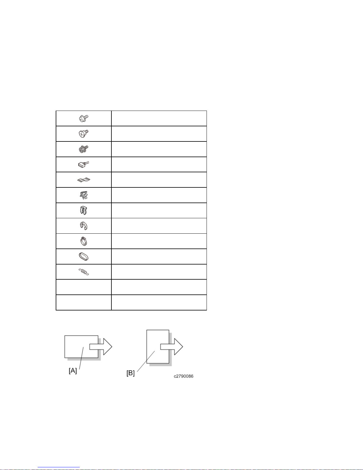
Symbols and Abbreviations
This manual uses several symbols and abbreviations. The meaning of those symbols and
abbreviations are as follows:
Screw
Shoulder screw
Black screw (TCRU)
Connector
FFC (Flat Film Connector)
Harness clamp
Clip
E-ring
C-ring
Timing belt
Spring
SEF Short Edge Feed
LEF Long Edge Feed
[A] Short Edge Feed (SEF)
[B] Long Edge Feed (LEF)

Cautions, Notes, etc.
The following headings provide special information:
FAILURE TO OBEY WARNING INFORMATION COULD RESULT IN SERIOUS INJURY
OR DEATH.
Obey these guidelines to ensure safe operation and prevent minor injuries.
This information provides tips and advice about how to best service the machine.
Trademarks
Bonjour is trademarks of Apple Inc., registered in the U.S. and other countries.
Java is a registered trademark of Oracle and/or its affiliates.
LINUX is the registered trademark of Linus Torvalds in the U.S. and other countries.
Microsoft, Windows, Windows Server, Windows Vista, and Internet Explorer are either registered
trademarks or trademarks of Microsoft Corporation in the United States and/or other countries.
Adobe and Reader are either registered trademarks or trademarks of Adobe Systems
Incorporated in the United States and/or other countries.
Red Hat is a registered trademark of Red Hat, Inc.
The SD is a trademark of SD-3C, LLC.
Other product names used herein are for identification purposes only and might be trademarks of
their respective companies. We disclaim any and all rights to those marks.
Microsoft product screen shots reprinted with permission from Microsoft Corporation.


PRODUCT INFORMATION
REVISION HISTORY
Page Date Added/Updated/New
None


Product Overview
SM 1-1 D245/D246/D247
Product
Information
1. PRODUCT INFORMATION
1.1 PRODUCT OVERVIEW
1.1.1 COMPONENT LAYOUT
No. Description No. Description
1 ADF unit (D247 only) 7 By-pass tray unit
2 Scanner unit 8 Paper feed unit (Option)
3 Paper exit / reverse unit (D246 /
D247)
Paper exit unit (D245)
9 Paper tray 1
4 Fusing unit 10 Laser unit
5 OPC drum 11 Toner supply unit
6 Duplex unit (D246 / D247 only)
Product Overview
SM 1-2 D245/D246/D247
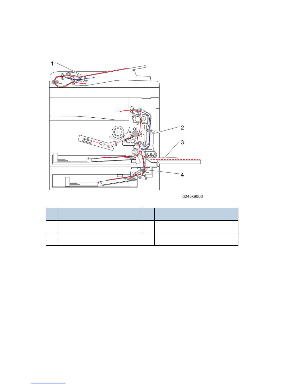
1.1.2 PAPER PATH
No. Description No. Description
1 ADF unit (D247 only) 3 By-pass tray
2 Duplex unit (D246/D247 only) 4 Paper feed unit (Option)
Product Overview
SM 1-3 D245/D246/D247
Product
Information
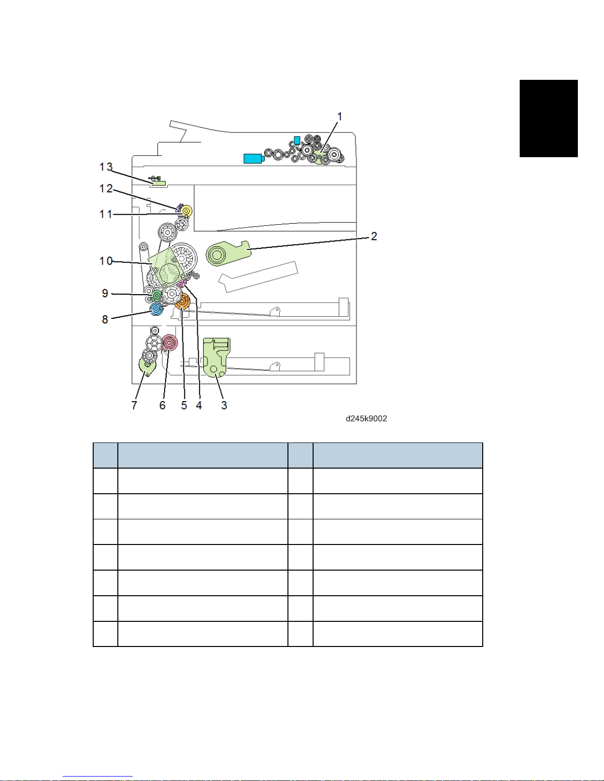
1.1.3 DRIVE LAYOUT
No. Description No. Description
1 ADF main motor (D247 only) 8 By-pass paper feed clutch
2 Toner supply motor 9 Duplex clutch (D246 / D247 only)
3 Tray lift motor (Option) 10 Main motor
4 Registration clutch 11 Reverse clutch (D246 / D247 only)
5 Paper feed clutch (Main) 12 Paper exit clutch (D246 / D247 only)
6 Paper feed clutch (Option) 13 Scanner motor
7 Transport motor (Option)

Product Overview
SM 1-4 D245/D246/D247
1.1.4 PARTS LAYOUT
ADF unit (D247 only)
No. Description No. Description
1 ADF registration sensor 5 ADF cover sensor
2 ADF main motor 6 ADF inverter solenoid
3 ADF pick-up solenoid 7 ADF main board
4 Original set sensor
Product Overview
SM 1-5 D245/D246/D247
Product
Information
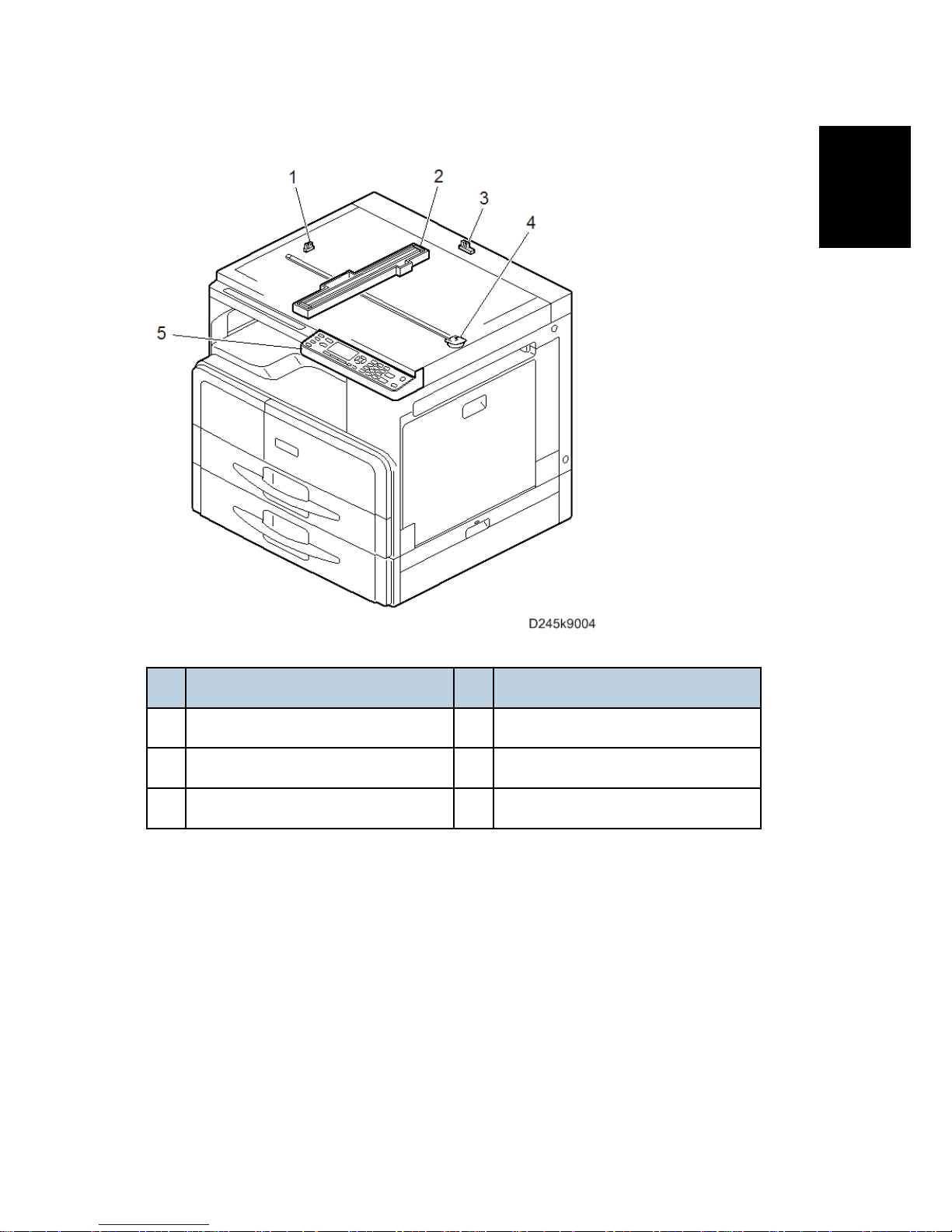
Scanner Unit
No. Description No. Description
1 Scanner HP sensor 4 Scanner motor
2 CIS unit 5 Operation panel
3 Platen cover sensor
Product Overview
SM 1-6 D245/D246/D247
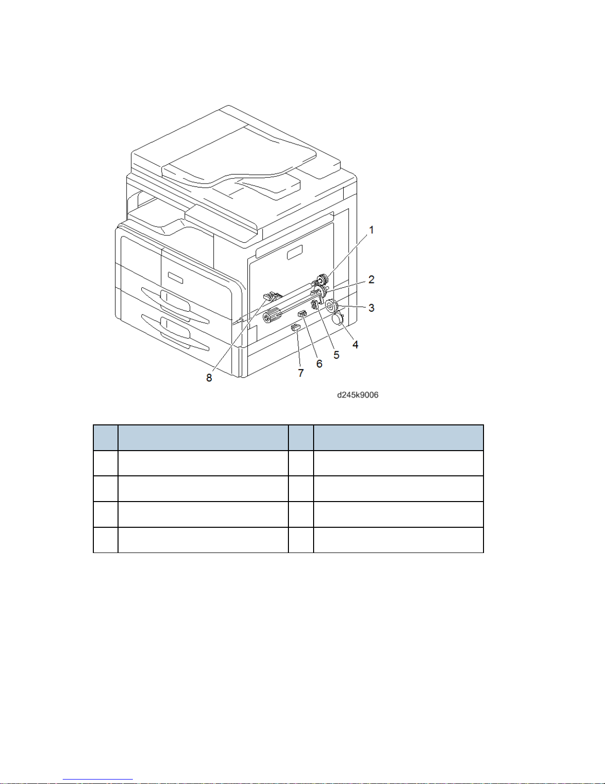
Paper Feed Unit
No. Description No. Description
1 Registration clutch 5 Registration sensor
2 Paper feed clutch (Main) 6 Paper feed sensor (Option)
3 Paper feed clutch (Option) 7 Paper end sensor (Option)
4 Transport motor (Option) 8 Paper end sensor (Main)
Product Overview
SM 1-7 D245/D246/D247
Product
Information
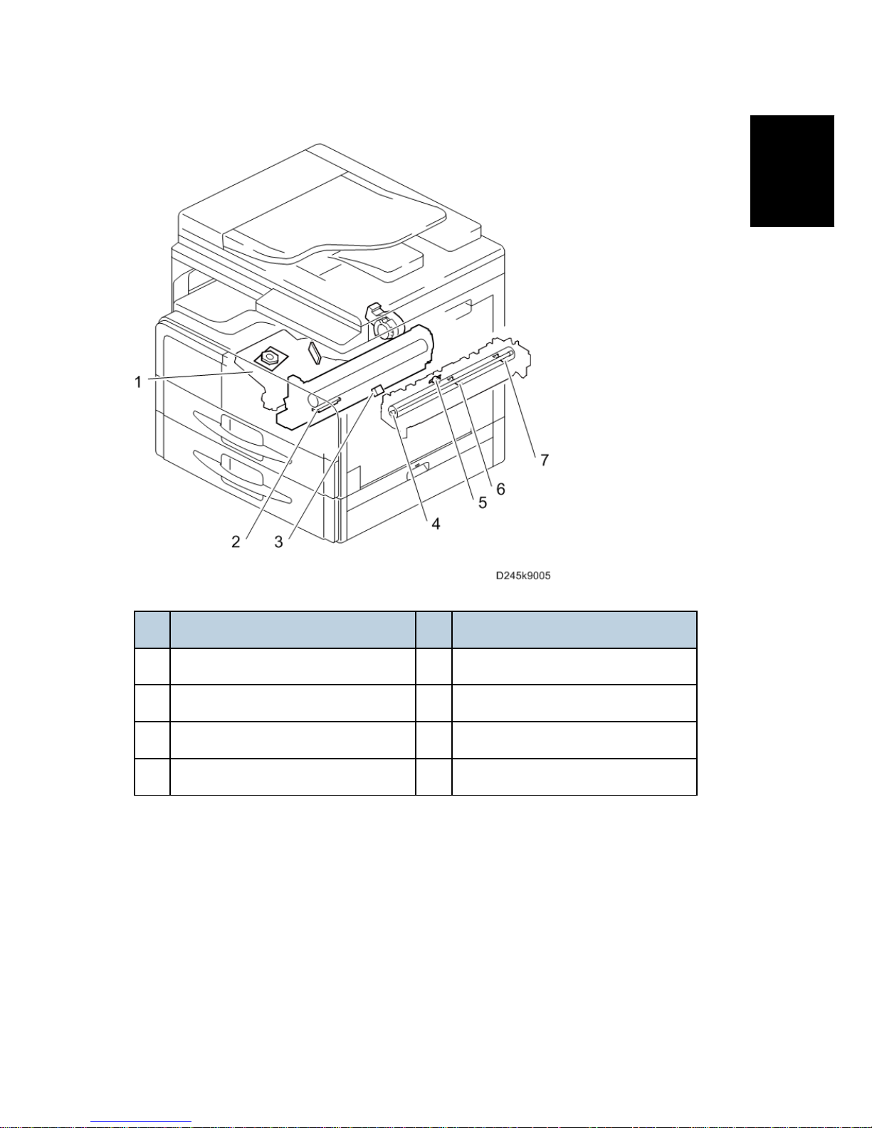
Laser Unit/ PCDU/ Fusing Unit
No. Description No. Description
1 Laser unit 5 Thermostat
2 TD sensor 6 Thermistor (Center)
3 ID sensor 7 Thermistor (End)
4 Fusing lamp
Product Overview
SM 1-8 D245/D246/D247
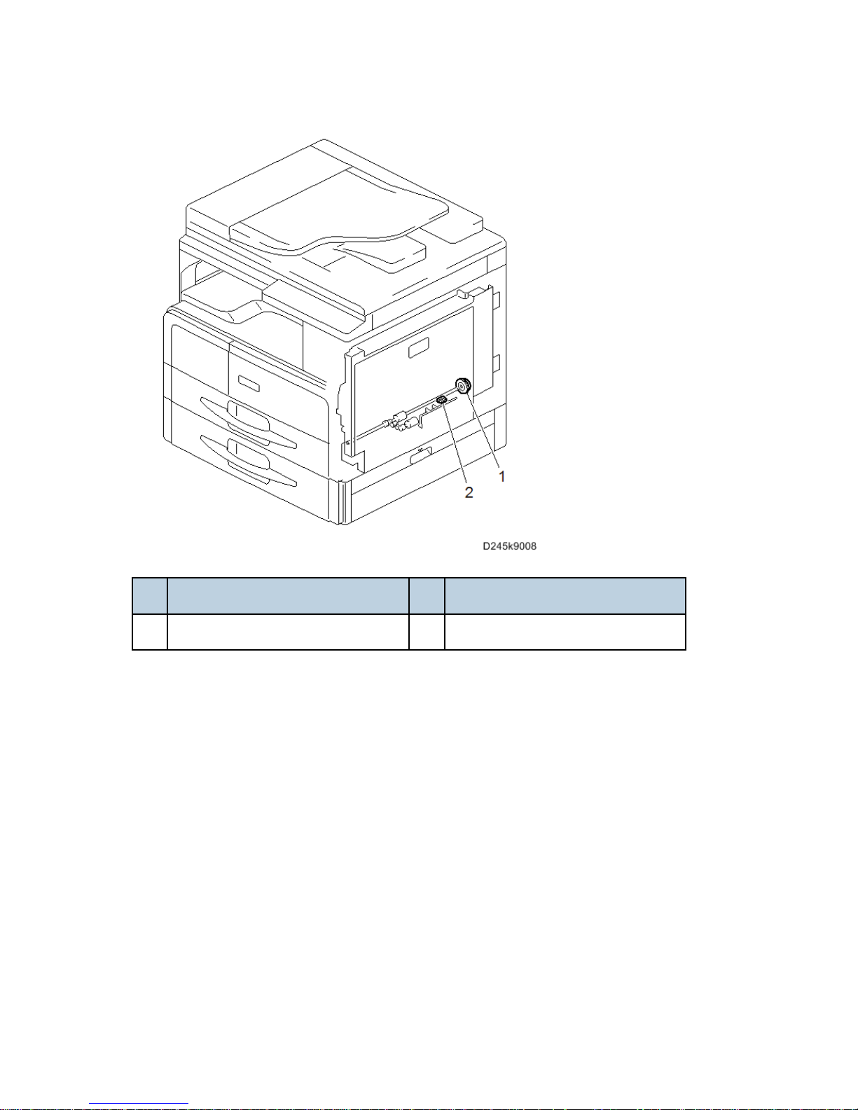
By-pass Unit
No. Description No. Description
1 By-pass paper feed clutch 2 By-pass paper end sensor
Product Overview
SM 1-9 D245/D246/D247
Product
Information
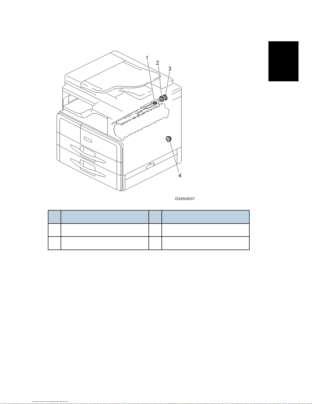
Paper Exit/ Reverse/ Duplex Unit
No. Description No. Description
1 Paper exit sensor 3 Reverse clutch (D246 / D247 only)
2 Paper exit clutch (D246 / D247 only) 4 Duplex clutch (D246 / D247 only)
Product Overview
SM 1-10 D245/D246/D247
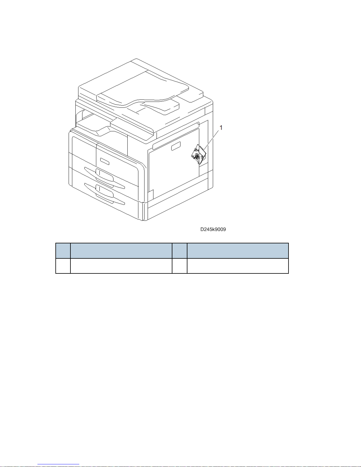
Drive Unit
No. Description No. Description
1 Main motor
Product Overview
SM 1-11 D245/D246/D247
Product
Information
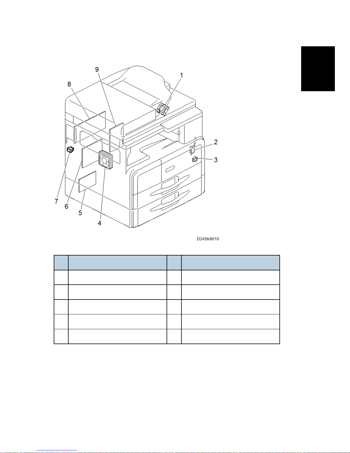
Electrical Component
No. Description No. Description
1 Exhaust fan 6 PSU
2 Door switch (Front door/Right door) 7 Main power switch
3 Right door switch 8 MPU
4 Main fan 9 HVP
5 PFU main board (Option)

Machine Codes and Peripherals Configuration
SM 1-12 D245/D246/D247
1.2 MACHINE CODES AND PERIPHERALS
CONFIGURATION
1.2.1 SYSTEM CONFIGURATION AND OPTIONS
No. Item Machine Code
1 Paper Feed Unit PB2020 D3B1
2 By-pass Tray Cover Type M16 D3B7
3 DDST Unit Type M16 D3B2
 Loading...