

Page 1

Model K-C3.5L
Machine Code:
B244/B276/B277/B268/B269
Field Service Manual
3 December, 2010
Page 2

Page 3

Safety Notices
Important Safety Notices
Prevention of Physical Injury
1. Before disassembling or assembling parts of the copier and peripherals, make sure that the power
cord is unplugged.
2. The wall outlet should be near the copier and easily accessible.
3. Note that some components of the copier and the paper tray unit are supplied with electrical voltage
even if the main power switch is turned off.
4. If a job has started before the copier completes the warm-up or initializing period, keep hands away
from the mechanical and electrical components because the starts making copies as soon as the warmup period is completed.
5. The inside and the metal parts of the fusing unit become extremely hot while the copier is operating.
Be careful to avoid touching those components with your bare hands.
Health Safety Conditions
Toner and developer are non-toxic, but if you get either of them in your eyes by accident, it may cause
temporary eye discomfort. Try to remove with eye drops or flush with water as first aid. If unsuccessful, get
medical attention.
Observance of Electrical Safety Standards
The copier and its peripherals must be installed and maintained by a customer service representative who
has completed the training course on those models.
Safety and Ecological Notes for Disposal
1. Do not incinerate toner bottles or used toner. Toner dust may ignite suddenly when exposed to an
open flame.
2. Dispose of used toner, developer, and organic photoconductors in accordance with local regulations.
(These are non-toxic supplies.)
3. Dispose of replaced parts in accordance with local regulations.
1
Page 4
Laser Safety
The Center for Devices and Radiological Health (CDRH) prohibits the repair of laser-based optical units
in the field. The optical housing unit can only be repaired in a factory or at a location with the requisite
equipment. The laser subsystem is replaceable in the field by a qualified Customer Engineer. The laser
chassis is not repairable in the field. Customer engineers are therefore directed to return all chassis and
laser subsystems to the factory or service depot when replacement of the optical subsystem is required.
of controls, or adjustment, or performance of procedures other than those specified in this manual
• Use
may result in hazardous radiation exposure.
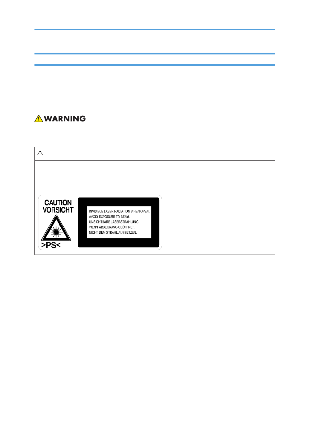
WARNING FOR LASER UNIT
WARNING: Turn off the main switch before attempting any of the procedures in the Laser Unit section.
Laser beams can seriously damage your eyes.
CAUTION MARKING:
2
Page 5

Symbols and Abbreviations
This
manual uses several symbols and abbreviations. The meaning of those symbols and abbreviations are
as follows:
See or Refer to
Clip ring
Screw
Connector
SEF Short Edge Feed
LEF Long Edge Feed
3
Page 6

TABLE OF CONTENTS
Safety Notices.....................................................................................................................................................1
Important Safety Notices...........................................................................................................................1
Laser Safety.....................................................................................................................................................
Symbols and Abbreviations...............................................................................................................................3
1. Product Information
Specifications....................................................................................................................................................11
Machine Configuration....................................................................................................................................
Overview..........................................................................................................................................................14
Component Layout.......................................................................................................................................14
Paper Path....................................................................................................................................................16
Drive Layout..................................................................................................................................................17
12
2. Installation
Installation Requirements.................................................................................................................................19
Environment..................................................................................................................................................19
Machine Level..............................................................................................................................................20
Minimum Space Requirements...................................................................................................................20
Power Requirements....................................................................................................................................21
Copier Installation............................................................................................................................................22
Power Sockets for Peripherals....................................................................................................................22
2
Accessory Check..........................................................................................................................................
Installation Procedure..................................................................................................................................23
Platen Cover Installation..................................................................................................................................28
Accessory Check..........................................................................................................................................28
Installation Procedure..................................................................................................................................28
ARDF Installation..............................................................................................................................................29
Accessory Check..........................................................................................................................................29
Installation Procedure..................................................................................................................................30
ADF Installation................................................................................................................................................33
Accessory Check..........................................................................................................................................33
Installation Procedure..................................................................................................................................34
Two-tray Paper Tray Unit Installation.............................................................................................................37
Accessory Check..........................................................................................................................................37
Installation Procedure..................................................................................................................................37
4
22
Page 7

One-tray Paper Tray Unit Installation.............................................................................................................42
Accessory Check..........................................................................................................................................42
Installation Procedure..................................................................................................................................42
One-Bin Tray Installation.................................................................................................................................46
Accessory Check..........................................................................................................................................46
Installation Procedure..................................................................................................................................46
Anti-condensation Heater Installation............................................................................................................49
Tray Heaters.....................................................................................................................................................50
Upper Tray Heater.......................................................................................................................................50
Lower Tray Heater (Two-tray Model Only)...............................................................................................52
Tray Heaters For The Optional Paper Feed Units.....................................................................................53
Key Counter Installation...................................................................................................................................57
Optional Counter Interface Unit Type A (B870-11).....................................................................................60
Accessory Check..........................................................................................................................................60
Installation Procedure..................................................................................................................................60
DDST Unit Type F (B865)................................................................................................................................62
Accessory Check..........................................................................................................................................62
Installing Expansion Component................................................................................................................62
Network Interface Board (D564)...................................................................................................................64
Component Check.......................................................................................................................................64
Installing Expansion Component................................................................................................................64
3. Preventive Maintenance
PM Tables.........................................................................................................................................................69
How to Reset the PM Counter.........................................................................................................................70
4. Replacement and Adjustment
General Cautions.............................................................................................................................................73
PCU (Photoconductor Unit).........................................................................................................................73
Transfer Roller..............................................................................................................................................73
Scanner Unit.................................................................................................................................................73
Laser Unit......................................................................................................................................................74
Fusing Unit....................................................................................................................................................74
Paper Feed...................................................................................................................................................74
Static Electricity............................................................................................................................................74
5
Page 8

Special Tools and Lubricants...........................................................................................................................75
Exterior Covers & Operation Panel................................................................................................................76
Rear Cover...................................................................................................................................................76
Rear Lower Cover (Two-tray Models Only)..............................................................................................77
Copy Tray.....................................................................................................................................................77
Upper Covers...............................................................................................................................................78
Left Cover......................................................................................................................................................79
Front Cover...................................................................................................................................................79
Front Right Cover.........................................................................................................................................80
Right Rear Cover..........................................................................................................................................80
Right Door (Duplex Unit (B244/B269/B277)).......................................................................................81
By-pass Tray.................................................................................................................................................82
Left Lower Cover (Two-tray Models Only)................................................................................................83
Right Lower Cover (Two-tray Models Only).............................................................................................83
Platen Cover Sensor....................................................................................................................................84
Scanner Unit.....................................................................................................................................................85
Exposure Glass/DF Exposure Glass .........................................................................................................85
Lens Block.....................................................................................................................................................86
Lamp Stabilizer Board And Exposure Lamp..............................................................................................87
Original Width/Length Sensor...................................................................................................................87
Scanner Motor.............................................................................................................................................89
Scanner Home Position Sensor...................................................................................................................90
Adjusting Scanner Positions........................................................................................................................90
Laser Unit..........................................................................................................................................................95
Location of Caution Decal...........................................................................................................................95
Toner Shield Glass.......................................................................................................................................96
Laser Unit......................................................................................................................................................96
LD Unit...........................................................................................................................................................97
Polygonal Mirror Motor..............................................................................................................................98
Laser Unit Alignment Adjustment................................................................................................................98
PCU Section...................................................................................................................................................101
PCU.............................................................................................................................................................101
Pick-off Pawls and Toner Density Sensor.................................................................................................102
6
Page 9

OPC Drum..................................................................................................................................................103
Charge Roller and Cleaning Brush..........................................................................................................104
Cleaning Blade..........................................................................................................................................104
Developer..................................................................................................................................................105
After Replacement or Adjustment.............................................................................................................106
Toner Supply Motor......................................................................................................................................107
Paper Feed Section........................................................................................................................................108
Paper Feed Roller .....................................................................................................................................108
Friction Pad................................................................................................................................................109
Paper End Sensor......................................................................................................................................109
Exit Sensor..................................................................................................................................................110
By-Pass Feed Roller and Paper End Sensor............................................................................................112
Registration Roller......................................................................................................................................113
By-Pass Paper Size Switch........................................................................................................................114
Registration Clutch ....................................................................................................................................115
Registration Sensor....................................................................................................................................115
Upper Paper Feed Clutch and By-Pass Feed Clutch..............................................................................116
Relay Clutch...............................................................................................................................................117
Relay Sensor..............................................................................................................................................117
Lower Paper Feed Clutch (Two-tray Models Only)................................................................................118
Vertical Transport Sensor (Two-tray Models Only)................................................................................118
Paper Size Switch......................................................................................................................................119
Image Transfer...............................................................................................................................................120
Image Transfer Roller................................................................................................................................120
Image Density Sensor...............................................................................................................................121
Fusing..............................................................................................................................................................122
Fusing Unit..................................................................................................................................................122
Thermistor...................................................................................................................................................122
Fusing Lamps..............................................................................................................................................123
Hot Roller Stripper Pawls..........................................................................................................................124
Hot Roller...................................................................................................................................................124
Thermostat..................................................................................................................................................125
Pressure Roller and Bushings....................................................................................................................125
7
Page 10

NIP Band Width Adjustment.....................................................................................................................126
Cleaning Roller..........................................................................................................................................127
Duplex Unit (Duplex Models B244/B269/B277 Only)..........................................................................128
Duplex Exit Sensor....................................................................................................................................128
Duplex Entrance Sensor............................................................................................................................129
Duplex Inverter Sensor..............................................................................................................................130
Duplex Transport Motor...........................................................................................................................131
Duplex Inverter Motor...............................................................................................................................131
Duplex Control Board...............................................................................................................................132
Other Replacements......................................................................................................................................133
Quenching Lamp.......................................................................................................................................133
High-Voltage Power Supply Board.........................................................................................................133
BICU (Base-Engine Image Control Unit).................................................................................................134
Main Motor...............................................................................................................................................135
Rear Exhaust Fan (B244/B269/B277 Only).......................................................................................135
Left Exhaust Fan.........................................................................................................................................136
PSU (Power Supply Unit)..........................................................................................................................137
Gearbox.....................................................................................................................................................138
Copy Adjustments Printing/Scanning..........................................................................................................141
Printing........................................................................................................................................................141
Scanning....................................................................................................................................................143
ADF Image Adjustment.............................................................................................................................145
5. System Maintenance
Service Program Mode.................................................................................................................................147
How to Enter the SP Mode.......................................................................................................................147
SP Mode Tables.............................................................................................................................................149
Using SP Modes.............................................................................................................................................150
Adjusting Registration and Magnification...............................................................................................150
ID Sensor Error Analysis (SP 2221).........................................................................................................151
Display APS Data (SP 4301 1)................................................................................................................151
Memory Clear...........................................................................................................................................153
Input Check (SP 5803).............................................................................................................................155
Output Check (SP 5804)..........................................................................................................................158
8
Page 11

Serial Number Input (SP 5811)...............................................................................................................160
NVRAM Data Upload/Download (SP 5824/5825)...........................................................................161
Test Pattern Print (SP 5902 1)..................................................................................................................163
Paper Jam Counters (SP 7504)...............................................................................................................165
SMC Print (SP 5990)................................................................................................................................166
Original Jam History Display (SP 7508).................................................................................................167
ADF APS Sensor Output Display (SP 6901)...........................................................................................168
Firmware Update Procedure .......................................................................................................................170
Engine (BICU) Firmware Update Procedure...........................................................................................170
GDI (Printer Scanner) Update Procedure................................................................................................171
6. Troubleshooting
Service Call Conditions.................................................................................................................................177
Summary....................................................................................................................................................177
SC Code Descriptions...............................................................................................................................178
Electrical Component Defects.......................................................................................................................193
Sensors.......................................................................................................................................................193
Switches.....................................................................................................................................................195
Blown Fuse Conditions..................................................................................................................................197
LED Display....................................................................................................................................................198
BICU...........................................................................................................................................................198
7. Energy Saving
Energy Save...................................................................................................................................................199
Energy Saver Modes................................................................................................................................199
Paper Save.....................................................................................................................................................203
Effectiveness of Duplex/Combine Function............................................................................................203
9
Page 12

10
Page 13

1. Product Information
1
Specifications
See "Appendices" for the following information:
General Specifications
•
• Supported Paper Sizes
• Option Equipment
11
Page 14
1. Product Information
1
Machine Configuration
12
Page 15

Copier
1
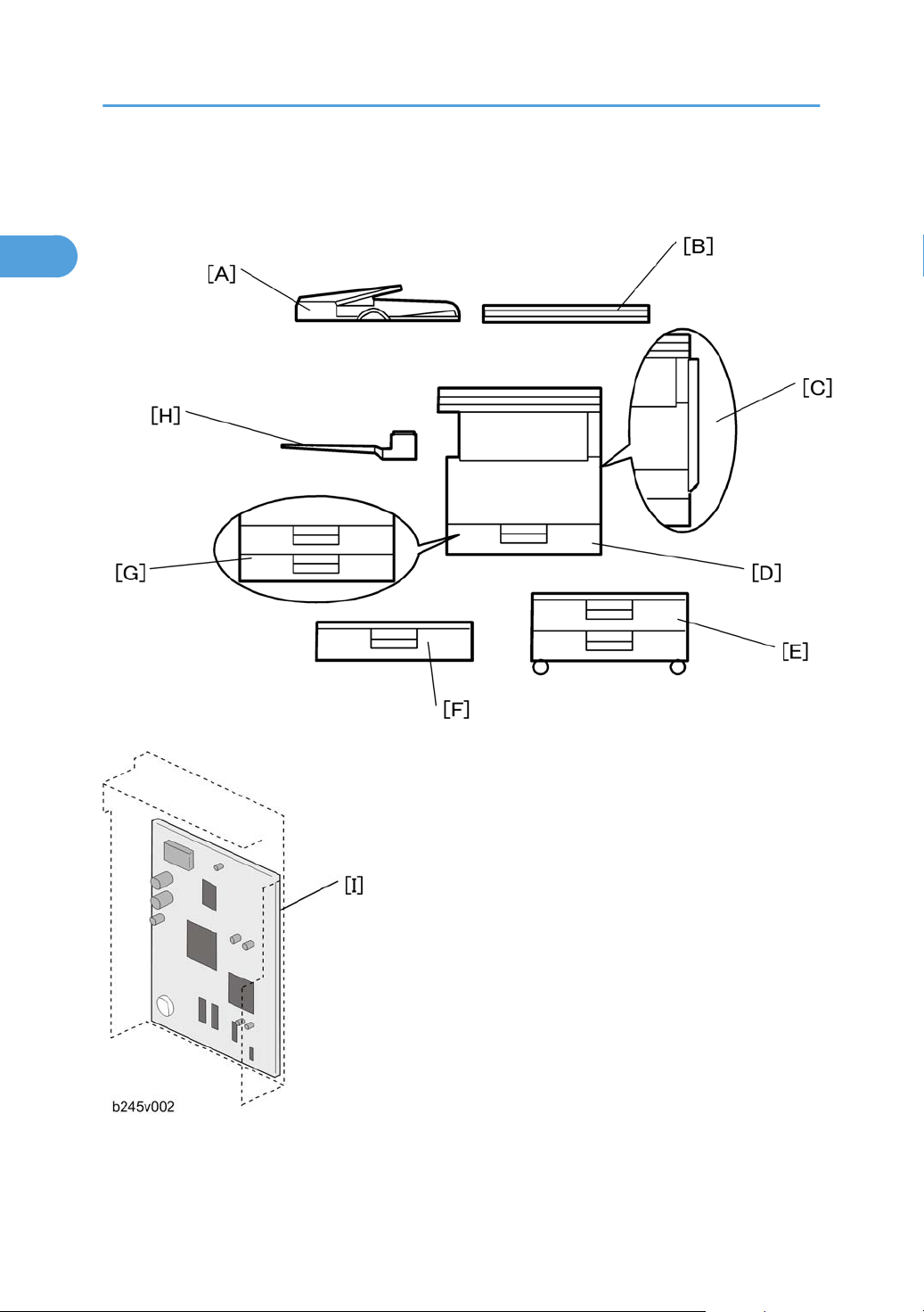
Machine Configuration
Unit/Component Machine Code Diagram
Copier (1-tray non-duplex model) B268/B276 [D]
Copier (2-tray with duplex) B244/B269/B277 [C] + [G]
Platen cover (optional) B406 [B]
ADF (optional) B813 [A]
ARDF (optional) B814 [A]
Paper tray unit–1 tray (optional) B385 [F]
Paper tray unit–2 trays (optional) B384 [E]
1-bin tray (optional) B621 [H]
GDI
• The optional GDI controller comes with a dedicated controller box and printer/scanner panel.
GDI controller (standard for B244 or optional for
B268/B269B276/B277)
B865 [I]
13
Page 16
1. Product Information
1
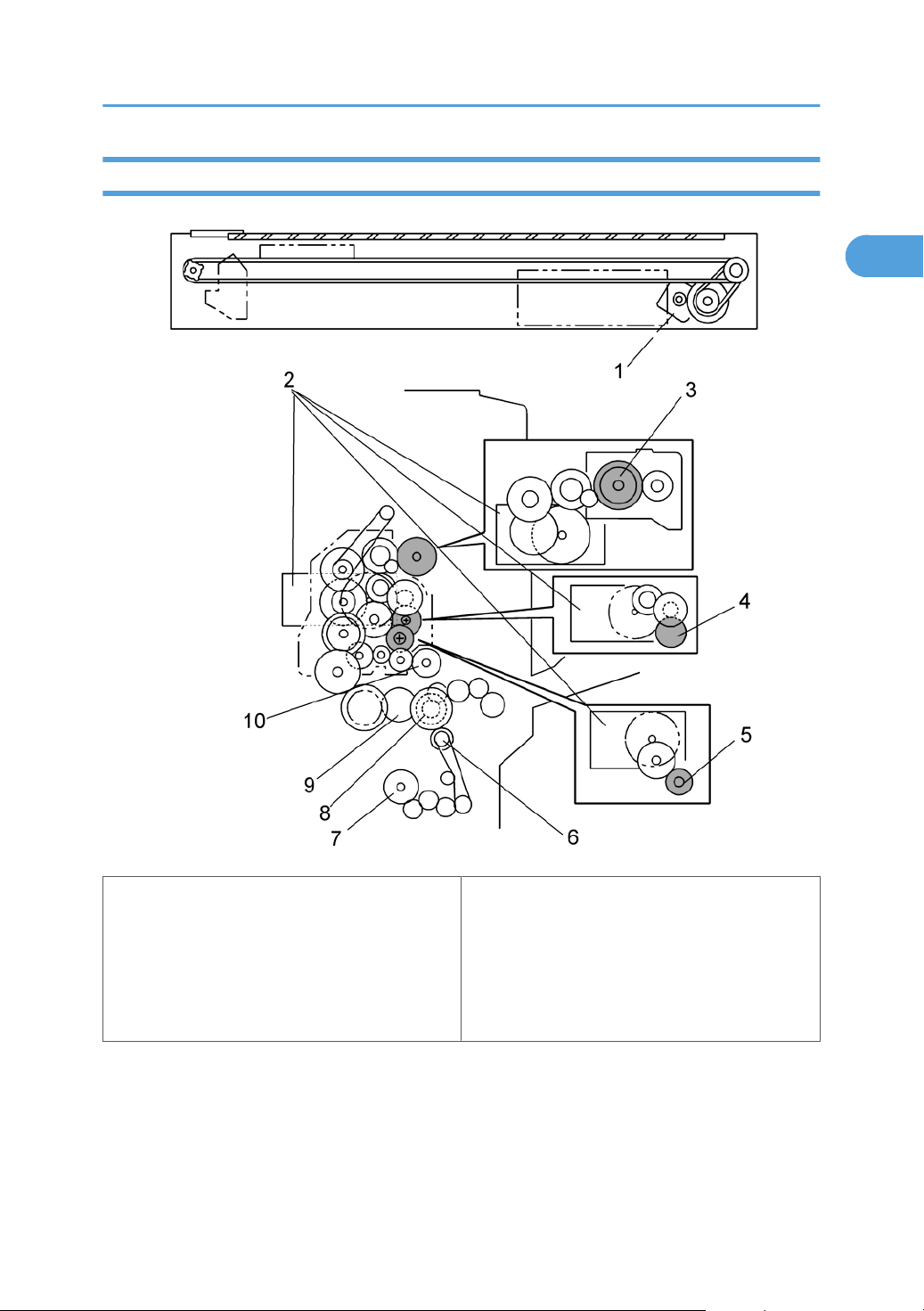
Overview
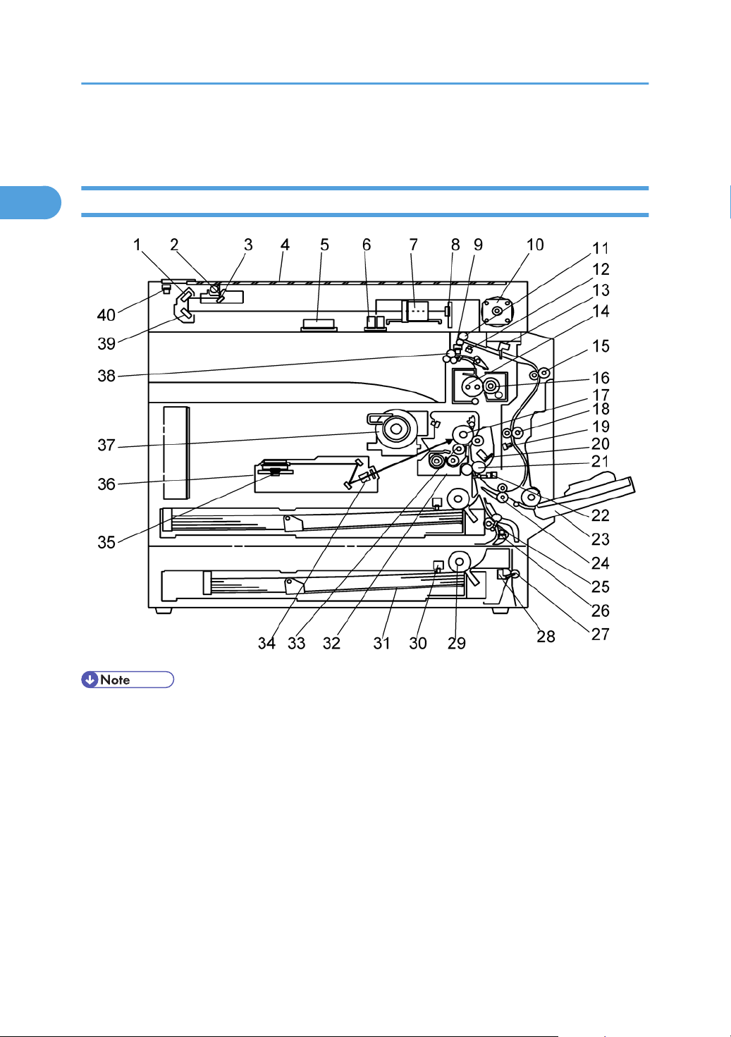
Component Layout
14
• The above illustration is the B244/B269/B277 model.
•
B268/B276: No duplex unit, one paper tray
Page 17

Overview
1
1. 2nd Mirror
2. Exposure Lamp
3. 1st Mirror
4. Exposure Glass
5. Original Width Sensors
6. Original Length Sensors
7. Lens Block
8. SBU
9. Exit Sensor
10. Scanner Motor
11. Inverter Roller
12. Duplex Inverter Sensor
13. Duplex Entrance Sensor
14. Hot Roller
15. Upper Transport Roller
16. Pressure Roller
17. OPC Drum
21. Registration Roller
22. Registration Sensor
23. By-pass Tray
24. Lower Transport Roller
25. Upper Relay Roller
26. Relay Sensor
27. Lower Relay Roller
28. Vertical Transport Sensor
29. Paper Feed Roller
30. Paper End Sensor
31. Bottom Plate
32. PCU
33. Development Roller
34. WTL
35. Polygon Mirror Motor
36. Laser Unit
37. Toner Supply Bottle Holder
18. Middle Transport Roller
19. Duplex Exit Sensor
20. Image Density Sensor
38. Exit Roller
39. 3rd Mirror
40. Scanner HP Sensor
15
Page 18
1. Product Information
1
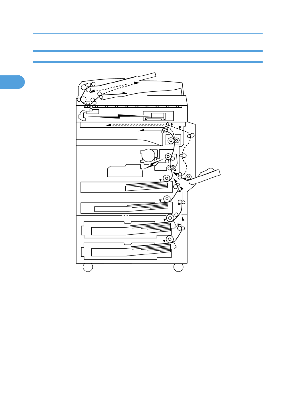
Paper Path
The B244/B269/B277 model has a duplex unit mounted on the right side of the machine.
All models have a by-pass tray.
16
Page 19
Drive Layout
1
Overview
1. Scanner Motor
2. Main Motor
3. Hot Roller
4. OPC Drum
5. Development Roller
6. Relay Clutch
7. Lower Paper Feed Clutch
8. By-pass Feed Clutch
9. Upper Paper Feed Clutch
10. Registration Clutch
17
Page 20

1. Product Information
1
18
Page 21
2. Installation
2
Installation Requirements
• Before installing options, please do the following:
• If there is a printer option in the machine, print out all data in the printer buffer.
• Turn off the main switch and disconnect the power cord, the telephone line, and the network cable.
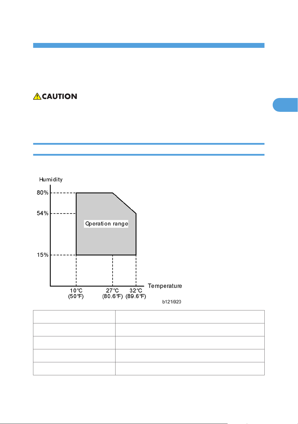
Environment
–Temperature and Humidity Chart–
• Temperature Range: 10°C to 32°C (50°F to 89.6°F)
• Humidity Range: 15% to 80% RH
• Ambient Illumination: Less than 1,500 lux (do not expose to direct sunlight)
• Ventilation: 3 times/hr/person or more
• Ambient Dust: Less than 0.075 mg/m3 (2.0 x 10⁻⁶ oz/yd3)
19
Page 22
2. Installation
2
• Avoid areas exposed to sudden temperature changes:
1) Areas directly exposed to cool air from an air conditioner.
2) Areas directly exposed to heat from a heater.
• Do not place the machine in areas where it can get exposed to corrosive gases.
• Do not install the machine at any location over 2,000 m (6,560 ft.) above sea level.
• Place the machine on a strong and level base. (Inclination on any side should be no more than 5
mm.)
• Do not place the machine where it is subjected to strong vibrations.
Machine Level
Front to back: Within 5 mm (0.2") of level
Right to left: Within 5 mm (0.2") of level
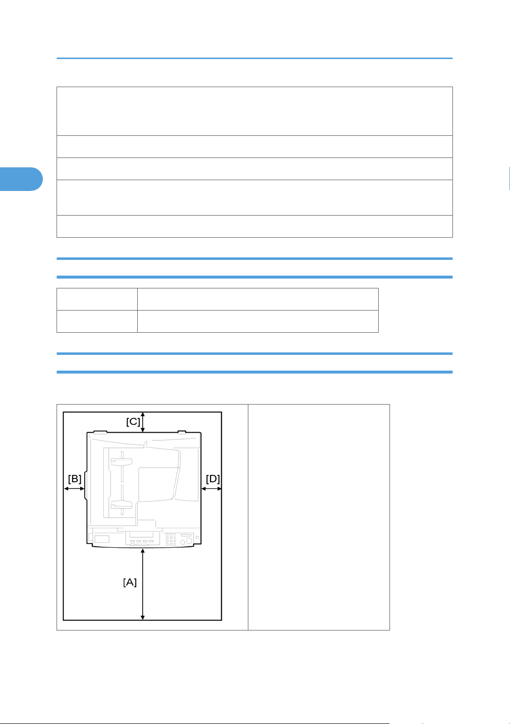
Minimum Space Requirements
Place the copier near the power source, providing clearance as shown:
A (front): 750 mm (30")
B (left): 150 mm (6")
C (rear): 50 mm (2")
D (right): 250 mm (10")
20
Page 23

Installation Requirements
2
The recommended 750 mm front space is sufficient to allow the paper tray to be pulled out. Additional
front space is required to allow operators to stand at the front of the machine.
Power Requirements
• Make
• Avoid multi-wiring.
• Be sure to ground the machine
Input voltage:
Taiwan:
Europe, Asia, China: 220 – 240 V, 50/60 Hz, 7 A
sure that the wall outlet is near the machine and easily accessible. After. completing installation,
make sure the plug fits firmly into the outlet.
110 – 120 V, 60 Hz, 12 A
21
Page 24
2. Installation
2
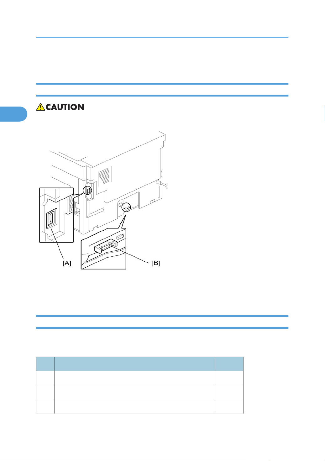
Copier Installation
Power Sockets for Peripherals
• Make sure to plug the cables into the correct sockets.
[A]: Socket for ADF/ARDF (Rated voltage output max. DC24 V)
[B]: Socket for paper tray unit (Rated voltage output max. DC24 V)
Accessory Check
Check that you have the accessories in this list.
Basic Machines
No. Description Q’ty
1 NECR-English /Multi-language 1
2 EU Safety Sheet 1
3 Laser Decal 1
22
Page 25

No. Description Q’ty
2
4 Model Name Plate 1
GDI Machines
No. Description Q’ty
1 NECR-English /Multi-language 1
2 Laser Decal 1
3 Model Name Plate 1
4 Operating Instructions 1
5 General Setting Guide 1
6 Copy Reference 1
7 Printer/Scanner Reference 1
Copier Installation
8 Network Reference 1
9 Quick Guide Copy Edition 1
10 Quick Guide Printer/Scanner Edition 1
11 Manual for this machine 1
12 Safety Information 1
Installation Procedure
• Unplug the machine power cord before starting the following procedure.
23
Page 26
2. Installation
2
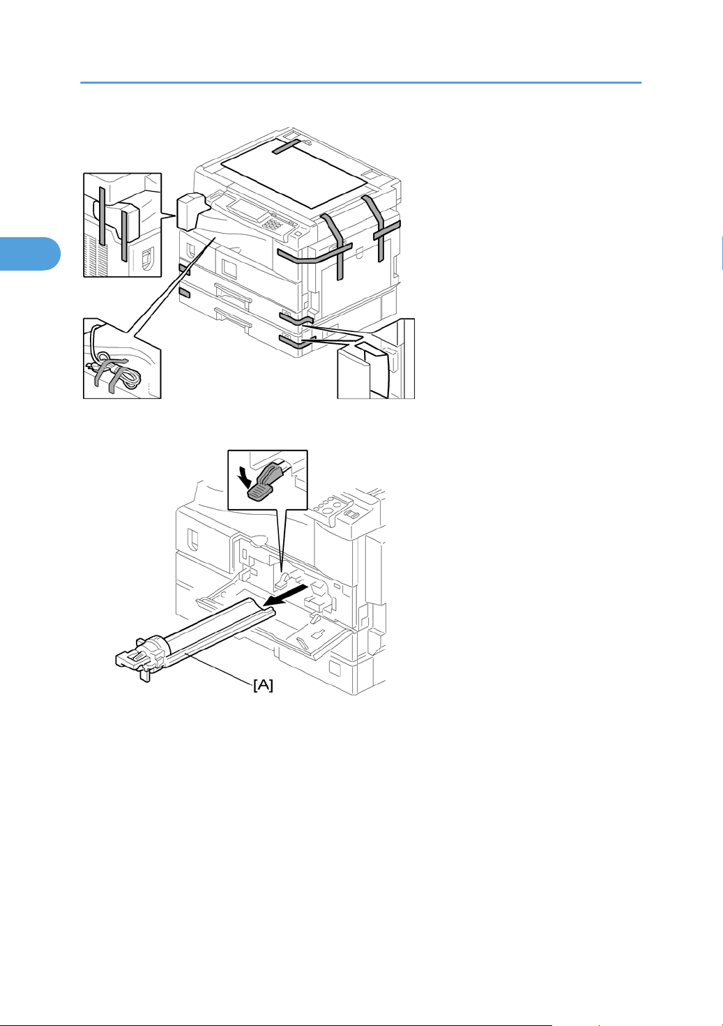
1. Remove filament tape and other padding.
2. Open the front door and remove the toner bottle holder [A]
24
Page 27
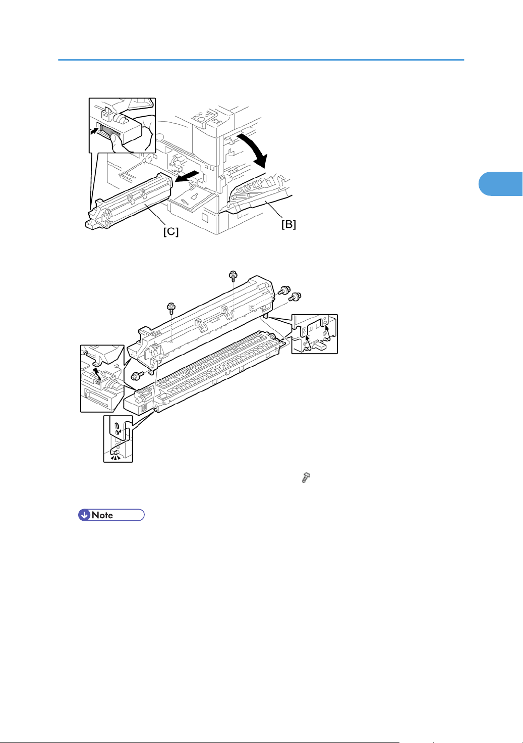
3. Open the right door [B], and remove the PCU (photo-conductor unit) [C].
2
Copier Installation
4. Separate the PCU into the upper part and the lower part ( x 5).
5.
Put a sheet of paper on a level surface and place the upper part on it.
• This prevents foreign material from getting on the sleeve rollers
25
Page 28

2. Installation
2
6. Distribute a pack of developer [D] to all openings equally.
• Do
not spill the developer on the gears [E]. If you have spilled it, remove the developer by using
a magnet or magnetized screwdriver.
• Do not turn the gear [E] too much. The developer may spill.
7. Reassemble the PCU and reinstall it.
8. Shake
9. Remove the bottle cap [G] and install the bottle on the holder. (Do not touch the inner cap [H].)
10. Set the holder (with the toner bottle) in the machine.
the toner bottle [F] several times. (Do not remove the bottle cap [G] before you shake the bottle.)
26
Page 29
Copier Installation
2
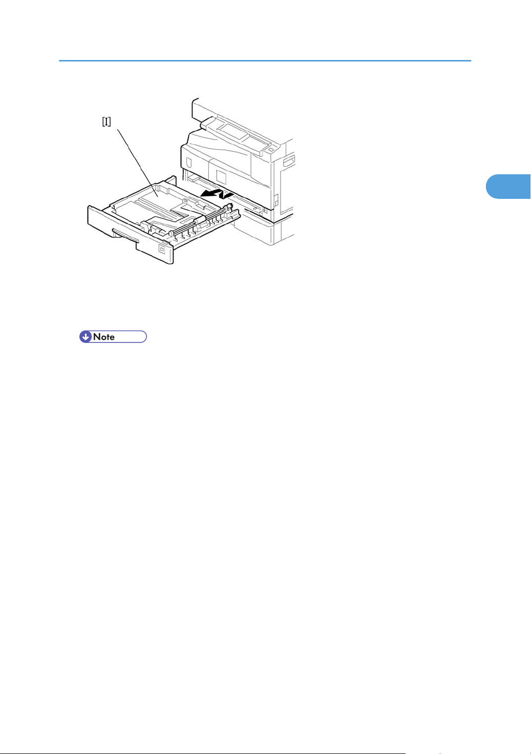
11. Pull out the paper tray [I] and turn the paper size dial to the appropriate size. Adjust the positions of
the end and side guides.
• To move the side guides, release the green lock on the rear side guide.
Install the optional ARDF, ADF, or platen cover.
12.
13. Plug in the main power cord and turn on the main switch.
14. Activate the SP mode and execute "Devlpr Initialize" (SP 2214 1).
15. Wait until the message "Completed" shows (about 45 seconds).
16. Activate the User Tools and select the menu "Language."
17. Specify a language. This language is used for the operation panel.
18. Load the paper in the paper tray and make a full size copy, and make sure the side-to-side and
leading edge registrations are correct.
27
Page 30
2. Installation
2
Platen Cover Installation
Accessory Check
Check that you have the accessories indicated below.
No. Description Q’ty
1 Stepped Screw 2
Installation Procedure
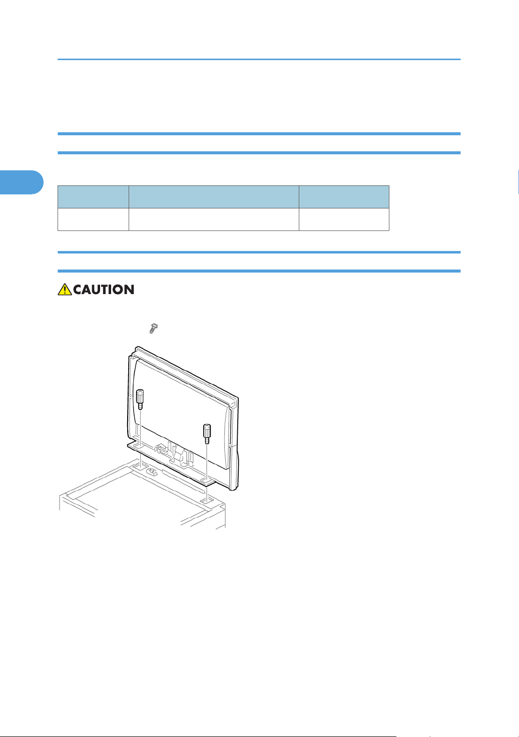
• Unplug the machine power cord before starting the following procedure.
Install the platen cover ( x 2).
28
Page 31

ARDF Installation
2
Accessory Check
Check the quantity and condition of the accessories against the following list.
No. Description Q’ty
1 Scale Guide 1
2 DF Exposure Glass 1
3 Stud Screw 2
4 Knob Screw 2
5 Original Size Decal 2
6 Screwdriver Tool 1
ARDF Installation
7 Attention Decal—Top Cover 1
8 Stamp Cartridge 1
9 Installation Procedure 1
29
Page 32

2. Installation
2
Installation Procedure
• Unplug the copier power cord before starting the following procedure.
1. Remove the strips of tape.
2. Remove the left scale [A] ( x 2).
3. Place
4. Peel off the backing [D] of the double-sided tape attached to the rear side of the scale guide [E], then
the DF exposure glass [B] on the glass holder. Make sure that the white mark [C] is on the bottom
at the front end.
install the scale guide (
x 2 [removed in step 2]).
30
5.
Install the two stud screws [F].
Page 33

6. Mount the ARDF on the copier, and then slide it to the front.
2
ARDF Installation
7. Secure the ARDF unit with the knob screws [G].
Connect the cable [H] to the copier.
8.
9. Attach the appropriate original size decal [I] as shown.
Attach an attention decal to the top cover.
10.
• The attention decals in the package are written in different languages.
31
Page 34

2. Installation
2
32
1. Open the ARDF [J].
Install the stamp cartridge [K] to the ARDF.
2.
3. Make a full size copy, and check that the side-to-side and leading edge registrations are correct. If
they are not, adjust the side-to-side and leading edge registrations. (
Adjustment")
p.145 "ADF Image
Page 35

ADF Installation
2
Accessory Check
Check the quantity and condition of the accessories against the following list.
No. Description Q'ty
1 Scale Guide 1
2 DF Exposure Glass 1
3 Stud Screw 2
4 Fixing Screw 2
5 Original Size Decal 2
6 Screwdriver Tool 1
ADF Installation
7 Attention Decal—Top Cover 1
8 Stamp Cartridge 1
9 Installation Procedure 1
33
Page 36

2. Installation
2
Installation Procedure
• Unplug the machine power cord before starting the following procedure.
1. Remove the strips of tape.
34
2. Remove the left scale [A] ( x 2).
3. Place
4. Peel off the backing [D] of the double-sided tape attached to the rear side of the scale guide [E], then
5.
6. Mount the ADF on the copier, and then slide it to the front.
the DF exposure glass [B] on the glass holder. Make sure that the white mark [C] is on the bottom
at the front end.
install the scale guide (
Install the two stud screws [F].
x 2 [removed in step 2]).
Page 37

7. Secure the ADF unit with the fixing screws [G].
2
ADF Installation
Connect the cable [H] to the copier.
8.
9. Attach the appropriate scale decal [I] as shown.
10. Attach an attention decal to the top cover.
• The attention decals in the package are written in different languages.
35
Page 38

2. Installation
2
11. Open the ADF [J].
Install the stamp cartridge [K] to the ADF
12.
13. Turn the main power switch on. Then check if the document feeder works properly.
14. Make a full size copy, and check that the side-to-side and leading edge registrations are correct. If
they are not, adjust the side-to-side and leading edge registrations (
Adjustment").
36
p.145 "ADF Image
Page 39

Two-tray Paper Tray Unit Installation
2
Two-tray Paper Tray Unit Installation
Accessory Check
Check the quantity and condition of the accessories against the following list.
No. Description Q’ty
1 Screw – M4x10 10
2 Unit Holder 2 x 2 pieces
3 Adjuster 1
4 Unit Holder 2
Installation Procedure
• If the optional printer unit is installed:
Print out all data in the printer buffer.
•
• Disconnect the network cable.
• Unplug the machine power cord before starting the following procedure.
37
Page 40

2. Installation
2
1. Remove the strips of tape. Make sure that you have removed all the strips of tape and all the pieces
of cardboard.
• After removing the tape that secures the peripheral components and cardboard to the paper
tray, make sure that there is no tape and/or tape reside remaining on the tray.
2. Attach the adjuster [A] to the base plate as shown.
• This step is not necessary if a cabinet is installed.
38
Page 41

3. Remove the cover [B] (1 rivet).
2
Two-tray Paper Tray Unit Installation
4. Set the copier on the paper tray unit.
• Before
placing the copier on the paper tray unit, make sure that the harness [C] is safe. The paper
tray unit does not function properly if the harness is damaged.
39
Page 42

2. Installation
2
5. One-tray copier model (B268/B276): Remove the 1st tray cassette [D].
Two-tray copier models (B244/B269/B277): Remove the 2nd tray cassette [D].
Install the two screws [E].
6.
7. Reinstall the tray cassette.
40
8. Install the two brackets [F] ( x 1 (each))
9.
Connect the connecting harness [G] to the copier.
• There are cutouts for the plugs on both sides. The left side has one cutout, and the right side has
two.
Page 43

Two-tray Paper Tray Unit Installation
2
10. Reinstall the cover removed in step 3 (1 rivet).
11. Install the four brackets with long supports [H] and covers [I] (2 screws each).
• These long supports prevent the unit from tipping over.
12. Rotate the adjuster (installed at step 2) to fix the machine in place.
• If a cabinet is installed, this step is unnecessary.
13. Load
the paper in the paper trays and make full size copies from each tray. Check if the side-to-side
and leading edge registrations are correct. If they are not, adjust the registrations (
Adjustments Printing/Scanning")
p.141 "Copy
41
Page 44

2. Installation
2
One-tray Paper Tray Unit Installation
Accessory Check
Check the quantity and condition of the accessories against the following list.
No. Description Q’ty
1 Screw – M4 x 10 2
2 Stepped Screw – M4 x 10 2
3 Unit Holder 2
Installation Procedure
• If the optional printer unit is installed:
•
Print out all data in the printer buffer.
• Disconnect the network cable.
• Unplug the machine power cord before starting the following procedure.
42
Page 45

One-tray Paper Tray Unit Installation
2
1. Remove the strips of tape. Make sure that you have removed all the strips of tape and all the pieces
of cardboard.
2. Remove the cover [A] (1 rivet).
• Before placing the copier on the paper tray unit, make sure that the harness [B] is safe. The paper
tray unit does not function properly if the harness is damaged.
3. Set the copier on the paper tray unit.
43
Page 46

2. Installation
2
4. One-tray copier model (B268/B276): Remove the 1st tray cassette [C].
Two-tray copier models (B244/B269/B277): Remove the 2nd tray cassette [C].
44
5. Install the two screws [D].
Reinstall the tray cassette.
6.
Page 47

One-tray Paper Tray Unit Installation
2
7. Install the two brackets [E]. (1 stepped screw each).
8.
Connect the connecting harness [F] to the copier.
• There
9. Reinstall the cover removed in step 2.
10. Load the paper in the paper tray and make full size copies from tray. Check if the side-to-side and
leading edge registrations are correct. If they are not, adjust the registrations (
Adjustments Printing/Scanning").
are cutouts for the plugs on both sides. The left side has one cutout, and the right side has
two.
p.141 "Copy
45
Page 48

2. Installation
2
One-Bin Tray Installation
Accessory Check
Check the quantity and condition of the accessories.
No. Description Q’ty
1 Installation procedure 1
2 One-bin sorter 1
3 Exit tray 1
4 Tapping screw M3 x 6 1
Installation Procedure
• Unplug the machine power cord before starting the following procedure.
1. Remove the inverter tray [A].
Remove the rail [B] (2 knob screws).
2.
3. Remove the cover [C] (1 rivet).
46
Page 49

4. Open the front cover [D].
2
One-Bin Tray Installation
Remove the front right cover [E] (
5.
Disconnect the connector [F].
6.
7. Cut the front cover as shown, to make an opening [G] for the 1-bin tray.
8. Install the 1-bin tray [H].
9. Make sure the connectors [I] are connected firmly.
x 1).
10. Fasten the screw.
11. Connect the connector [J] that you removed in step 6.
47
Page 50

2. Installation
2
• Make sure that the connector is connected
12. Reattach the front right cover [K].
Close the front cover [L].
13.
14. Install the exit tray [M] as follows:
• Keep the front end higher than the rear end.
• Push the left hook into the opening in the copier.
• Push the right hook into the opening in the copier.
15. Pull the support [N] out of the left end of the exit tray.
16. Insert the support into the left end of the paper exit tray [O] (of the copier).
17. Turn the main switch on.
18. Check the operation.
48
Page 51

Anti-condensation Heater Installation
2
Anti-condensation Heater Installation
• Unplug the machine power cord before starting the following procedure.
1. Remove the exposure glass.
2.
Remove the left cover.
3. Pass the connector [A] through the opening [B].
4. Install the anti-condensation heater [C], as shown.
5. Join the connectors [A, D].
6. Clamp the harness with the clamp [E].
7. Reinstall the left cover and exposure glass.
49
Page 52

2. Installation
2
Tray Heaters
• Unplug the machine power cord before starting the following procedure.
Upper Tray Heater
50
1. Remove the 1st tray cassette [A].
Remove the rear cover.
2.
Page 53

3. Pass the connector [B] through the opening [C] and install the tray heater [D] ( x 1).
2
Tray Heaters
4. Install the relay harness [E].
Fix the harness with the clamp [F].
5.
6. Reinstall the 1st tray cassette and the rear cover.
51
Page 54

2. Installation
2
Lower Tray Heater (Two-tray Model Only)
52
1. Remove the 2nd tray cassette [A].
Remove the rear lower cover.
2.
3. B244/B269/B277 only: Remove the DCB [B] with bracket (
Pass the connector [C] through the opening [D] and install the tray heater [E] (
4.
Join the connectors [F].
5.
6. Reinstall the 2nd tray cassette, DCB, and rear lower cover.
x 4, x 3).
x 1).
Page 55

Tray Heaters For The Optional Paper Feed Units
2
1. Remove the rear cover [A].for the paper tray unit
Tray Heaters
One-tray paper feed unit:
53
Page 56

2. Installation
2
Two-tray paper feed unit:
2. Two-tray unit only: Remove the cable guide [B].
Install the clamps [C].
3.
One-tray paper feed
unit:
54
Page 57

Two-tray paper feed
2
unit:
4. Pass the connector [D] through the opening [E].
Install the tray heater [F] (
5.
x 1)
Tray Heaters
One-tray paper feed unit:
55
Page 58

2. Installation
2
Two-tray paper feed unit:
6. Clamp the cables [G], as shown.
7. Join the connectors [H].
8. Two-tray unit only: Reinstall the cable guide.
9. One-tray copier model (B268/B276): Remove the 1st tray cassette.
Two-tray copier models (B244/B269/B277): Remove the 2nd tray cassette.
10. Remove the two screws [I] and install the two hexagonal socket screws [J].
11.
Reinstall the 1st tray/2nd tray(s) and rear cover.
56
Page 59

Key Counter Installation
2
• Unplug the machine power cord before starting the following procedure.
Key Counter Installation
1. Remove the left cover.
2.
Remove the rear cover.
3. Cut the cap [A] with nippers.
4. Punch out the small hole [B] using a screwdriver.
5. Hold the key counter plate nuts [C] on the inside of the key counter bracket [D] and insert the key
counter holder [E].
6. Secure the key counter holder to the bracket (
7.
Install the key counter cover [F] (
x 2).
x 2).
57
Page 60

2. Installation
2
8. Connect the connector [G] to CN126 on the BICU.
Hold the harness with the clamps [H][I][J].
9.
• The relay harness is not included in the key counter bracket accessories
10.
Join the relay harness [K] with the connector [L].
11. Reinstall the rear cover.
58
Page 61

12. Pass the relay harness through the opening [M] and reinstall the left cover.
2
Install the stepped screw [N].
13.
Key Counter Installation
14. Join the connectors [O].
15. Pass the joined connectors through the opening of the key counter holder assembly [P], and put the
connectors inside the assembly.
16. Hook the key counter holder assembly onto the stepped screw [N]. Check that the harness is not
caught between the left cover and the key counter holder assembly.
17. Secure the key counter holder assembly with the screw [Q].
59
Page 62

2. Installation
2
Optional Counter Interface Unit Type A (B870-11)
Accessory Check
No. Description Q’ty
1 Screw: M3x6 4
2 Bind: 80 mm 1
3 Locking Stud 4
4 Saddle Clamp 1
5 EMC Caution Sheet 1
6 Harness 1
7 ROHS Caution Sheet (China only) 1
Installation Procedure
60
Page 63

1. Unplug the DF cable [A] (if installed).
2
2. Rear cover [B] ( x 6)
3. Attach the bridge board [A] (Locking stud x 4).
Optional Counter Interface Unit Type A (B870-11)
Connect the harness [B] to CN140 [C] (13 pins) on the BICU.
4.
5. Clamp the harness in two places [D].
6. Connect the harness for the external key counter device to CN4 (20 pins) on the bridge board [A].
7. Reattach the rear cover (
x 6).
61
Page 64

2. Installation
2
DDST Unit Type F (B865)
Accessory Check
No. Description Q’ty
1 Cover-CPS EU 1
2 USB Cable 1
3 Tapping Screw-M3X6 6
4 Sheet-EULA 1
5 Seal-Caution 1
6 EMC Caution Sheet 1
7 Caution Sheet 1
8 Installation Procedure 1
Installing Expansion Component
• Unplug the machine power cord before starting the following procedure.
1. Remove the rear cover [A] ( x 6).
62
Page 65

2. Remove one screw [B] from the BICU.
2
DDST Unit Type F (B865)
3. Connect
three openings [F][G][H] hold the controller box.
4. Fasten the screws (
Re-attach the rear cover [A] (
5.
the controller box [D] to the BICU. Make sure that the BICU [E] is not damaged and that the
x 7).
x 6).
63
Page 66

2. Installation
2
Network Interface Board (D564)
• This option is used only for the model with the DDST Unit Type F (B865).
Component Check
No. Description Q’ty
1 Ferrite Core 1
2 Flexible Cable 1
3 Network Interface Board 1
Installing Expansion Component
• Unplug the machine power cord before starting the following procedure.
1. Unplug the DF cable [A] (if installed).
64
Page 67

2. Rear cover [B] ( x 6)
2
3. Remove the SD slot cover [A] ( x 1).
Remove the interface slot cover [B] (
4.
Network Interface Board (D564)
x 2).
5. Remove the controller box cover [A] ( x 7).
65
Page 68

2. Installation
2
6. Install the network interface board [A] into the interface slot of the controller ( x 2).
• Use two screws, which have been removed in step 4.
7. Install
8. Reinstall the controller box cover (
9. Attach the ferrite core [A] to the network cable [B]. The end of the ferrite core must be about 10 cm
10.
the flexible cable [A] in the slot [B] of the controller with the blue part facing upward, and then
the other end [C] of the flexible cable in the slot [D] of the network interface board.
• Lock the flexible cable with the cable holder [E].
x 7) and SD slot cover ( x 1).
(4") from the end of the cable [C].
• This procedure is only for machines with the B866 option.
Install the network cable in the Ethernet slot.
66
Page 69

Network Interface Board (D564)
2
11. Re-attach the rear cover [A] ( x 6).
12. Turn on the machine.
13. Check if the "Network Setting" is displayed on the LCD (User Tools > Network Setting). If not, check
the procedure above again.
67
Page 70

2. Installation
2
68
Page 71

3. Preventive Maintenance
3
PM Tables
See "Appendices" for the "PM Tables".
69
Page 72

3. Preventive Maintenance
3
How to Reset the PM Counter
After preventive maintenance work, reset the PM counter (SP 7804 1) as follows.
1. Activate the SP mode.
Select SP 7804 1 (Reset–PM Counter).
2.
3. Press the OK key [A]. The message "Execute" shows.
70
Page 73

4. Press the button [B] below the message "Execute."
3
How to Reset the PM Counter
The messages "Execute?" followed by "Cancel" and "Execute" show.
5.
6. To reset the PM counter, press the button [C] below the message "Execute."
71
Page 74

3. Preventive Maintenance
3
7. Wait until the message "Completed" shows.
Quit the SP mode.
8.
72
Page 75

4. Replacement and Adjustment
4
General Cautions
Do not turn off the main switch while any of the electrical components are active. Doing so may result in
damage to units (such as the PCU) as they are pulled out or replaced.
PCU (Photoconductor Unit)
The PCU consists of the OPC drum, charge roller, development unit, and cleaning components. Observe
the following precautions when handling the PCU.
1. Never
2. Never use alcohol to clean the drum. Alcohol will dissolve the drum surface.
3. Store the PCU in a cool dry place.
4. Do not expose the drum to corrosive gases (ammonia, etc.).
5. Do not shake a used PCU, as this may cause toner and developer to spill out.
6. Dispose of used PCU components in accordance with local regulations.
touch the drum surface with bare hands. If the drum surface is dirty or if you have accidentally
touched it, wipe it with a dry cloth, or clean it with wet cotton and then wipe it dry with a cloth.
Transfer Roller
1. Never touch the surface of the transfer roller with bare hands.
2.
Be careful not to scratch the transfer roller, as the surface is easily damaged.
Scanner Unit
1. Use alcohol or glass cleaner to clean the exposure and scanning glass. This will reduce the static
charge on the glass.
2.
Use a blower brush or a water-moistened cotton pad to clean the mirrors and lenses.
3. Make sure to not bend or crease the exposure lamp’s ribbon cable.
4. Do not disassemble the lens unit. This will cause the lens and copy image to get out of focus.
5. Do not turn any of the CCD positioning screws. This will put the CCD out of position.
73
Page 76

4. Replacement and Adjustment
4
Laser Unit
1. Do not loosen or adjust the screws securing the LD drive board on the LD unit. This will put the LD unit
out of adjustment.
2. Do not adjust the variable resistors on the LD unit. These are adjusted at the factory.
3. The polygonal mirror and F-theta lens are very sensitive to dust.
4. Do not touch the toner shield glass or the surface of the polygonal mirror with bare hands.
Fusing Unit
1. After installing the fusing thermistor, make sure that it is in contact with the hot roller and that the roller
can rotate freely.
2. Be careful to avoid damage to the hot roller stripper pawls and their tension springs.
3. Do not touch the fusing lamp and rollers with bare hands.
4. Make sure that the fusing lamp is positioned correctly and that it does not touch the inner surface of
the hot roller.
Paper Feed
1. Do not touch the surface of the paper feed rollers.
2. To avoid misfeeds, the side and end fences in each paper tray must be positioned correctly so as to
align with the actual paper size.
must run SP 2214 to initialize the TD sensor after you install a new PCU. After starting initialization,
• You
be sure to wait for it to reach completion (wait for the motor to stop) before you re-open the front
cover or turn off the main switch.
• If the optional tray heater or optics anti-condensation heater is installed, keep the machine's power
cord plugged in even while the main switch is off, to keep the heater(s) energized.
Static Electricity
Always touch a grounded surface to discharge static electricity from your hands before you handle SD
cards, printed circuit boards, or memory boards.
74
Page 77

Special Tools and Lubricants
4
Special Tools and Lubricants
Part Number Description Q’ty
A0069104 Scanner Positioning Pins (4 pins/set) 1 set
A2929500 Test Chart S5S (10 pcs/set) 1 set
N8036701 4MB Flash Memory Card 1
A2579300 Grease Barrierta S552R 1
52039502 Grease G-501 1
75
Page 78

4. Replacement and Adjustment
4
Exterior Covers & Operation Panel
Rear Cover
76
1. Unplug the DF cable [A] (if installed).
2. Rear cover [B] ( x 6)
Page 79

Rear Lower Cover (Two-tray Models Only)
4
1. Rear cover (see above) or tray harness cover [A] (1 rivet).
2. Rear lower cover [B] ( x 2)
Exterior Covers & Operation Panel
Copy Tray
1. Copy tray [A] ( x 2)
77
Page 80

4. Replacement and Adjustment
4
Upper Covers
1. Platen Cover, ARDF, or ADF (if installed)
2.
Rear cover
3. Left upper cover [A] (
4.
Front upper left cover [B] (
5.
Operation panel [C] (
6.
Right upper cover [D] (
7.
Push the cover to the rear side to release the hooks.
8. Top rear cover [E] (
x 2)
x 3)
x 4, x 1)
x 1, 3 hooks)
x 1)
78
Page 81

Left Cover
4
1. Left cover [A] ( x 3)
Exterior Covers & Operation Panel
Front Cover
1. Pull out the (top) paper tray.
2.
Open the front door [A].
3. Front cover [B] (
x 4)
79
Page 82

4. Replacement and Adjustment
4
Front Right Cover
1. Open the front door [A].
2.
Front right cover [B] (
x 1)
Right Rear Cover
1. Right upper cover ( p.78 "Upper Covers")
2. Open the duplex unit (B244/B269/B277 only).
3. Right rear cover [A] ( x 1)
80
Page 83

Right Door (Duplex Unit (B244/B269/B277))
4
1. Right rear cover (see above)
2.
Open the right door [A].
Exterior Covers & Operation Panel
3. Open the clamps [B] and disconnect the two connectors [C] or three connectors (B244/B269/
B277).
4. Right door
81
Page 84

4. Replacement and Adjustment
4
By-pass Tray
1. Right rear cover (above)
Open the right door.
2.
3. Release the by-pass tray cable from the clamps (see [B] on the preceding procedure) and disconnect
the connector (5-pin connector with colored wires).
4. Cable holder [A] (B244/B269/B277 only)
5. Front-side clip ring [B]
6. Front-side pin [C] (You can push the pin from behind the right door.)
7. Front-side tray holder arm [D]
8. Remove the rear-side clip ring, pin, and tray holder arm in the same manner.
9. By-pass tray [E]
82
Page 85

Left Lower Cover (Two-tray Models Only)
4
Exterior Covers & Operation Panel
1. Left lower cover [A] ( x 2)
Right Lower Cover (Two-tray Models Only)
1. Right lower cover [A] (1 pin)
83
Page 86

4. Replacement and Adjustment
4
Platen Cover Sensor
1. Top rear cover
2.
Platen cover sensor [A] (
x 1)
84
Page 87

Scanner Unit
4
Exposure Glass/DF Exposure Glass
Scanner Unit
Exposure Glass
1. Front upper left cover ( p.78 "Upper Covers")
2.
Left scale [A] (
3.
Rear scale [B] (
4.
Exposure glass [C]
• Make
on the frame when you reinstall the exposure glass.
x 2)
x 3)
sure that the mark is at the rear left corner, and that the left edge is aligned to the support
DF Exposure Glass
1. Front upper left cover ( p.78 "Upper Covers")
Left scale [A]
2.
3. DF exposure glass [D]
• Make sure that the mark [E] is on the bottom at the front end when reinstall the exposure glass.
85
Page 88

4. Replacement and Adjustment
4
Lens Block
not touch the paint-locked screws on the lens block. The position of the lens assembly (black part)
• Do
is adjusted before shipment.
• Do not grasp the PCB or the lens assembly when you handle the lens block. The lens assembly may
slide out of position.
86
1. Exposure glass ( p.85 "Exposure Glass/DF Exposure Glass ")
2. Lens cover [A] ( x 5)
3. Disconnect the flat cable [B].
4. Lens block [C] ( x 4).
• Adjust the image quality ( p.141 "Copy Adjustments Printing/Scanning") after you install a
new lens block.
Page 89

Lamp Stabilizer Board And Exposure Lamp
4
1. Operation panel ( p.78 "Upper Covers")
Scanner Unit
2.
Exposure glass (
3.
Slide the first scanner to a position where the front end of the lamp is visible.
4. Place one hand under the lamp stabilizer board [A] and release the hook [B].
5. Lamp stabilizer board (
6.
Press the plastic latch [C] and push the front end of the lamp toward the rear.
7. Lamp [D] (with the cable)
p.85 "Exposure Glass/DF Exposure Glass ")
x 2)
Original Width/Length Sensor
1. Exposure glass ( p.85 "Exposure Glass/DF Exposure Glass ")
87
Page 90

4. Replacement and Adjustment
4
2. Original width sensor [A] ( x 1, x 1)
3. Lens block ( p.86)
4. Original length sensor [B] ( x 1, x 1)
Sensor Positions
Sensor positions vary according to regions as shown below.
• [A]: Asia (including Taiwan; excluding China), Europe
• [B]: China (Sensor positions for China model (8K/16K))
Sensor Positions for China Model (8K/16K)
This procedure is for China models only. You must rearrange the positions of the original width and length
sensors for the copier to detect the following original sizes:
• 8K SEF (270 x 390 mm)
• 16K SEF (195 x 270 mm)
• 16K LEF (270 x 195 mm)
After you have rearranged the positions, the sensors work as listed in the table. Rearrange the sensor
positions as follows:
Original Size Length Sensors Width Sensors
8K-SEF L1 L2 W1 W2
16K-SEF X X X O
16K-LEF X O O O
16K-SEF O O X O
88
Page 91

1. Specify SP mode settings:
4
Select SP 4305 1, and specify 2 (=Yes). The machine will detect 8K/16K rather than A3/A4/B4/
B5 (A3-SEF/B4-SEF 8K-SEF; B5-SEF/A4-SEF 16K-SEF; B5-LEF/A4-LEF 16K-LEF).
2. Turn off the main switch.
3. Exposure glass ( p.85 "Exposure Glass/DF Exposure Glass ").
4. Original width/length sensors [A] [B]
5. Rearrange the sensor positions [C] [D].
6. Turn on the main switch and check the operations.
Scanner Motor
Scanner Unit
upper cover, front upper left cover, operation panel, top rear cover (
1. Left
DF Exposure Glass ")
Exposure glass (
2.
Rear exhaust fan [A] (B244/B269/B277 only)
3.
4. Scanner motor [B] (
• Install the belt first, and then set the spring when you reassemble. Fasten the leftmost screw (viewed
from the rear), and fasten the other two screws.
•
Adjust the image quality after you install the motor.
p.85 "Exposure Glass/DF Exposure Glass ")
x 3, x 1, 1 spring, 1 belt)
p.85 "Exposure Glass/
89
Page 92

4. Replacement and Adjustment
4
Scanner Home Position Sensor
1. Left upper cover, top rear cover ( p.87)
2.
Exposure glass, DF exposure glass (if installed) (
3.
Disconnect the connector [A].
4. Scanner left lid [B] (
5.
Sensor tape [C].
6. Scanner home position sensor [D]
x 7)
p.85)
Adjusting Scanner Positions
• Grasp the front and rear ends (not the middle) of the first scanner when you manually move it. The
first scanner may be damaged if you press, push, or pull its middle part.
Overview
1. Adjust the scanner positions when the first scanner [C] and second scanner [B] are not parallel with
the side frames [A], or, when you have replaced one or more of the scanner belts.
90
Page 93

2. To adjust the scanner positions, do either of the following:
4
•
To adjust the belt contact points on the first scanner (See " Adjusting the First Scanner Contact
Points" below.)
• To adjust the belt contact points on the scanner bracket (See ”Adjusting the Second Scanner
Contact Points" below.)
Scanner Unit
3. The two actions above have the same objectives--to align the following holes and marks:
• The adjustment holes [H] [J] in the first scanner
• The adjustment holes [H] [J] in the second scanner
• The alignment marks [G] [I] on the frames
4. The scanner positions are correct when these holes and marks are aligned.
91
Page 94

4. Replacement and Adjustment
4
Adjusting the First Scanner Contact Points
1. A(R)DF or platen cover
Operation panel, top rear cover (
2.
Exposure glass (
3.
Loosen the 2 screws [A] [F].
4.
5. Slide the 1st and 2nd scanners, or one of them, to align the following holes and marks
6. The adjustment holes in the first scanner
7. The adjustment holes in the second scanner
8. The alignment marks on the frames
9. Insert the positioning tools [D] [E] through the holes and marks.
10. Check that the scanner belts [B] [C] [G] [H] are properly set between the bracket and the 1st scanner.
11. Tighten the screws [A] [F].
12. Remove the positioning tools.
13. Reassemble the machine and check the operation.
92
p.85)
p.78 "Upper Covers").
Page 95

Adjusting the Second Scanner Contact Points
4
1. A(R)DF or platen cover
Scanner Unit
2.
Operation panel, top rear cover (
3.
Exposure glass (
4.
Rear exhaust fan [A] (
5.
Controller bracket [B] (
6.
Disconnect the platen-cover-sensor connector [C].
7. Rear frame [D] (
8.
Scale bracket [E] (
p.85)
x 2)
x 3)
x 7)
x 2)
p.78 "Upper Covers").
93
Page 96

4. Replacement and Adjustment
4
9. Loosen the 2 screws [F].
10.
Slide the 2nd scanner to align the following holes and marks
11. The adjustment holes in the first scanner
12. The adjustment holes in the second scanner
13. The alignment marks on the frames
14. Insert the positioning tools [G] [H] through the holes and marks.
15. Check that the scanner belts are properly set in the brackets.
16. Remove the positioning tools.
17. Reassemble the machine and check the operation.
94
Page 97

Laser Unit
4
laser beam can seriously damage your eyes. Be absolutely sure that the main power switch is off
• The
and that the machine is unplugged before you access the laser unit.
Location of Caution Decal
Laser Unit
95
Page 98

4. Replacement and Adjustment
4
Toner Shield Glass
1. Open the front door.
2.
Lift the toner cartridge latch [A].
3. Press the toner shield glass cover [B] to the left and pull it out.
4. Pull out the toner shield glass [C].
Laser Unit
96
1. Toner shield glass.
2.
Copy tray
Page 99

3. Pull out the (upper) paper tray.
4
4. Front cover ( p.79)
5. Laser unit [A] ( x 2, x 4)
• The screw at the left front position [B] is longer than the other three.
LD Unit
• Do not touch the paint-locked screw [A]. The LD position is adjusted before shipment.
Laser Unit
1. Laser unit ( p.96)
2.
LD unit [B] (
• Do not screw the LD unit in too tightly when you install it.
x 1)
97
Page 100

4. Replacement and Adjustment
4
Polygonal Mirror Motor
1. Laser unit ( p.96)
2.
Two rubber bushings [A]
3. Laser unit cover [B] (
4.
Polygonal mirror motor [C] (
5.
After reassembling, adjust the image quality (
x 1)
x 4)
p.141 "Copy Adjustments Printing/Scanning").
Laser Unit Alignment Adjustment
• Reinstall the copy exit tray before you turn the main switch on. The laser beam may go out of the
copier when the copy exit tray is not installed. The laser beam can seriously damage your eyes.
98
 Loading...