

Ricoh PE-P4, M199, M204, MF4, M200 Field Service Manual
...
Model PE-P4/MF4
Machine Code:
(M199/M200/M203/M204)
Field Service Manual
14th February, 2014


Safety Notices
Important Safety Notices
Prevention of Physical Injury
1. Before disassembling or assembling parts of the machine and peripherals, make sure that the
machine power cord is unplugged.
2. The wall outlet should be near the machine and easily accessible.
If any adjustment or operation check has to be made with exterior covers off or open while the
3.
main switch is turned on, keep hands away from electrified or mechanically driven components.
4. The machine drives some of its components when it completes the warm-up period. Be careful to
keep hands away from the mechanical and electrical components as the machine starts operation.
5. The inside and the metal parts of the fusing unit become extremely hot while the machine is
operating. Be careful to avoid touching those components with your bare hands.
Health Safety Conditions
Toner is non-toxic, but if you get either of them in your eyes by accident, it may cause temporary eye
discomfort. Try to remove with eye drops or flush with water as first aid. If unsuccessful, get medical
attention.
Observance of Electrical Safety Standards
The machine and its peripherals must be serviced by a customer service representative who has
completed the training course on those models.
Safety and Ecological Notes for Disposal
1. Do not incinerate toner bottles or used toner. Toner dust may ignite suddenly when exposed to an
open flame.
2. Dispose of used toner, the maintenance unit which includes developer or the organic
photoconductor in accordance with local regulations. (These are non-toxic supplies.)
Dispose of replaced parts in accordance with local regulations.
3.
• To prevent a fire or explosion, keep the machine away from flammable liquids, gases, and
aerosols. A fire or an explosion might occur.
1
• The Controller board on the MF model contains a lithium battery. The danger of explosion exists if
a battery of this type is incorrectly replaced. Replace only with the same or an equivalent type
recommended by the manufacturer. Discard batteries in accordance with the manufacturer's
instructions and local regulations.
Laser Safety
The Center for Devices and Radiological Health (CDRH) prohibits the repair of laser-based optical units
in the field. The optical housing unit can only be repaired in a factory or at a location with the requisite
equipment. The laser subsystem is replaceable in the field by a qualified Customer Engineer. The laser
chassis is not repairable in the field. Customer engineers are therefore directed to return all chassis and
laser subsystems to the factory or service depot when replacement of the optical subsystem is required.
• Use of controls, or adjustment, or performance of procedures other than those specified in this
manual may result in hazardous radiation exposure.
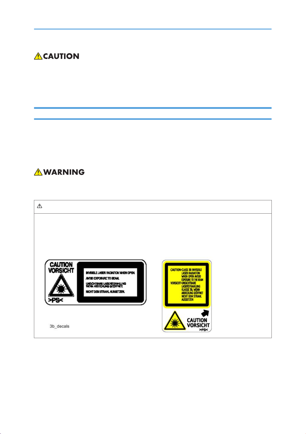
WARNING
WARNING:
Turn off the main switch before attempting any of the procedures in the Laser Optics Housing Unit
section. Laser beams can seriously damage your eyes.
CAUTION MARKING:
2
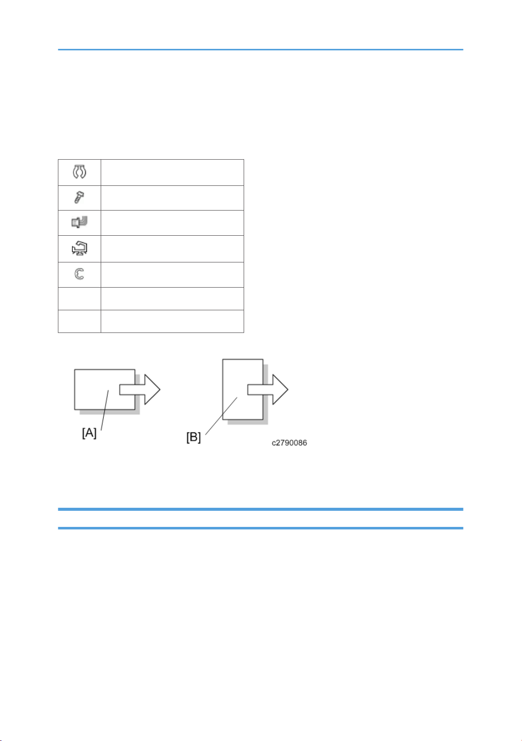
Symbols, Abbreviations and Trademarks
This manual uses several symbols and abbreviations. The meaning of those symbols and abbreviations
are as follows:
Clip ring
Screw
Connector
Clamp
E-ring
SEF Short Edge Feed
LEF Long Edge Feed
[A] Short Edge Feed (SEF)
[B] Long Edge Feed (LEF)
Trademarks
Microsoft®, Windows®, Windows Server®, Windows Vista®, and Internet Explorer® are either
registered trademarks or trademarks of Microsoft Corporation in the United States and/or other
countries.
The proper name of Internet Explorer 6 is Microsoft® Internet Explorer® 6.
Adobe, Acrobat, PostScript, and Reader are either registered trademarks or trademarks of Adobe
Systems Incorporated in the United States and/or other countries.
PCL® is a registered trademark of Hewlett-Packard Company.
Other product names used herein are for identification purposes only and might be trademarks of their
respective companies. We disclaim any and all rights to those marks.
3

TABLE OF CONTENTS
Safety Notices.....................................................................................................................................................1
Important Safety Notices............................................................................................................................... 1
Prevention of Physical Injury................................................................................................................. 1
Health Safety Conditions...................................................................................................................... 1
Observance of Electrical Safety Standards.........................................................................................1
Safety and Ecological Notes for Disposal...........................................................................................1
Laser Safety.....................................................................................................................................................2
Symbols, Abbreviations and Trademarks.........................................................................................................3
Trademarks..................................................................................................................................................... 3
1. Product Information
General Specifications.................................................................................................................................... 11
Supported Paper Sizes.................................................................................................................................... 12
Machine Overview.......................................................................................................................................... 13
Component Layout.......................................................................................................................................13
Engine (M199/M200)......................................................................................................................13
Engine (M203/M204)......................................................................................................................14
ADF (only for M203/M204)............................................................................................................15
Scanner (only for M203/M204)..................................................................................................... 15
Paper Path.................................................................................................................................................... 16
ADF (only for M203/M204)............................................................................................................16
Drive Layout..................................................................................................................................................17
Machine Configuration....................................................................................................................................19
Printer Model (M199/M200)...................................................................................................................19
MF Model (M203/M204)........................................................................................................................19
Guidance for Those Who are Familiar with Predecessor Products..............................................................20
2. Installation
Installation Requirements................................................................................................................................. 21
Environment..................................................................................................................................................21
Machine level...............................................................................................................................................22
Machine Space Requirements....................................................................................................................22
Printer Models (M199/M200).........................................................................................................22
MF Models (M203/M204)..............................................................................................................23
Power Requirements.................................................................................................................................... 23
4

Installation Procedure..................................................................................................................................24
3. Preventive Maintenance
Preventive Maintenance.................................................................................................................................. 25
4. Replacement and Adjustment
Before You Start............................................................................................................................................... 27
General Precautions.................................................................................................................................... 27
AIO.......................................................................................................................................................27
Laser Unit............................................................................................................................................. 28
Transfer Roller......................................................................................................................................
Fusing................................................................................................................................................... 28
Paper Feed...........................................................................................................................................28
Scanner Unit (for M203/M204)......................................................................................................28
Releasing Plastic Latches............................................................................................................................. 29
After Servicing the Machine........................................................................................................................29
Lithium Batteries (MF Models).................................................................................................................... 30
Special Tools.................................................................................................................................................... 31
Exterior Covers................................................................................................................................................. 32
Rear Cover................................................................................................................................................... 32
Rear Cover (Printer Models).............................................................................................................. 32
Rear Cover (MF Models)................................................................................................................... 33
Right Cover...................................................................................................................................................34
Left Cover......................................................................................................................................................35
Front Cover Unit...........................................................................................................................................36
Scanner Unit (only for MF Models)................................................................................................................38
Scanner Unit.................................................................................................................................................38
28
ADF (only for MF Models).............................................................................................................................. 42
ADF Unit........................................................................................................................................................42
Original Tray................................................................................................................................................43
ADF Pick-Up Roller...................................................................................................................................... 43
ADF Feed Roller........................................................................................................................................... 44
ADF Separation Pad....................................................................................................................................45
ADF Front Cover ......................................................................................................................................... 45
ADF Rear Cover...........................................................................................................................................46
5

ADF Motor....................................................................................................................................................47
ADF Top Cover............................................................................................................................................ 48
Document Sensor.........................................................................................................................................49
ADF Feed Sensor......................................................................................................................................... 52
Laser Unit.......................................................................................................................................................... 53
Caution Decal Locations............................................................................................................................. 53
Laser Optics Housing Unit...........................................................................................................................53
After replacing the laser optics housing unit..................................................................................... 57
Printing out the test chart to make sure MUSIC was performed correctly...................................... 58
Checking that MUSIC was Performed Correctly..............................................................................60
If MUSIC has not been performed successfully................................................................................60
AIO Cartridge (All In One Cartridge)............................................................................................................ 62
AIO Cartridge.............................................................................................................................................. 62
Black AIO Motor......................................................................................................................................... 62
Color AIO Motor......................................................................................................................................... 65
Image Transfer..................................................................................................................................................68
Image Transfer Belt Unit.............................................................................................................................. 68
After replacing the image transfer belt unit.......................................................................................69
ITB (Image Transfer Belt) Cleaning Unit.....................................................................................................69
Agitator Motor............................................................................................................................................. 70
ITB (Image Transfer Belt) Contact Motor................................................................................................... 72
ITB (Image Transfer Belt) Contact Sensor.................................................................................................. 73
TM (Toner Mark) Sensor Base....................................................................................................................74
Waste Toner Bottle Set Sensor................................................................................................................... 75
Waste Toner Overflow Sensor................................................................................................................... 77
Paper Transfer.................................................................................................................................................. 78
Transfer Unit................................................................................................................................................. 78
Transfer Roller.............................................................................................................................................. 78
Registration Roller........................................................................................................................................ 80
Reassembling the registration roller unit............................................................................................81
Registration Sensor...................................................................................................................................... 81
Registration Clutch....................................................................................................................................... 82
Image Fusing.................................................................................................................................................... 83
6

Fusing Unit.................................................................................................................................................... 83
Fusing Lamp..................................................................................................................................................85
When Reinstalling the Fusing Lamp................................................................................................... 88
When Reassembling the Fusing Unit..................................................................................................89
Transport/Fusing Motor..............................................................................................................................90
Paper Feed........................................................................................................................................................92
Paper Feed Clutch........................................................................................................................................92
Paper Feed Roller........................................................................................................................................ 92
Separation Pad............................................................................................................................................ 93
Paper End Sensor.........................................................................................................................................94
Paper Exit.......................................................................................................................................................... 96
Paper Exit Roller...........................................................................................................................................96
Paper Exit Sensor......................................................................................................................................... 97
Electrical Components..................................................................................................................................... 99
Controller Board.......................................................................................................................................... 99
Controller Board (Printer Models)..................................................................................................... 99
Controller Board (MF Models)........................................................................................................100
EGB (Engine Board)..................................................................................................................................102
EGB (Printer Models)........................................................................................................................102
EGB (MF Models)............................................................................................................................ 104
FCU (only for MF Models)....................................................................................................................... 106
Operation Panel........................................................................................................................................ 107
OPU............................................................................................................................................................110
OPU (Printer Models).......................................................................................................................110
OPU (MF Models)............................................................................................................................110
Wi-Fi Board............................................................................................................................................... 111
Interlock Switches......................................................................................................................................112
Fusing Fan Motor.......................................................................................................................................113
Fusing Stripper Pawl Solenoid..................................................................................................................114
Fusing Pressure Release Sensor................................................................................................................117
LSU Fan Motor...........................................................................................................................................117
ID Chip Board............................................................................................................................................118
PSU............................................................................................................................................................. 119
7

High Voltage Power Supply Board..........................................................................................................121
Temperature/Humidity Sensor.................................................................................................................122
Duplex Motor............................................................................................................................................
Speaker (only for MF Models).................................................................................................................125
EEPROM.....................................................................................................................................................126
Checking that MUSIC was Performed Correctly........................................................................... 128
122
5. System Maintenance Reference
Service Menu................................................................................................................................................. 129
Overview....................................................................................................................................................129
Menu Mode......................................................................................................................................129
Special Mode................................................................................................................................... 129
Maintenance Mode Menu (MF Models)................................................................................................130
Menu List ...........................................................................................................................................130
Service Mode (Printer Models)................................................................................................................142
Menu List ...........................................................................................................................................142
Fax Service Test Menu (only for MF Models).........................................................................................146
Entering the Fax Service Test Menu................................................................................................ 146
Selecting an Item.............................................................................................................................. 146
Going into the Next Level/ Returning to the Previous Level..........................................................147
Exiting the Maintenance Mode Menu............................................................................................147
Menu List............................................................................................................................................147
Size Mismatch Detection Menu............................................................................................................... 148
Entering the Size Mismatch Detection Menu..................................................................................148
Configuration, Maintenance and Test Page Information........................................................................... 149
Overview....................................................................................................................................................149
To Print the Configuration Page/ Test Page/ Maintenance Page (Printer Models)................... 149
To Print the Configuration Page/ Maintenance Page (MF Models)............................................149
Error Log.....................................................................................................................................................150
Counter and Coverage (only for Printer Models)...................................................................................150
Configuration Page.......................................................................................................................... 150
Firmware Updating........................................................................................................................................152
Checking the Machine Firmware Version............................................................................................... 152
To Print the Configuration Page (Printer Models)...........................................................................152
8

To Print the Configuration Page (MF Models)................................................................................152
Updating the Controller Firmware........................................................................................................... 152
Procedure.......................................................................................................................................... 153
Updating the Engine Firmware.................................................................................................................155
Boot Loader Firmware...............................................................................................................................158
6. Troubleshooting
Service Call Conditions.................................................................................................................................159
Summary.................................................................................................................................................... 159
Engine SC...................................................................................................................................................159
SC 1xx (Other Error)........................................................................................................................ 159
SC 2xx (Laser Optics Error).............................................................................................................160
SC 3xx (Charge Error)..................................................................................................................... 161
SC 4xx (Image Transfer and Transfer Error).................................................................................. 162
SC 5xx (Motor and Fusing Error)....................................................................................................164
SC 6xx (Communication and Other Error).....................................................................................168
Controller SC............................................................................................................................................. 169
SC8xx................................................................................................................................................169
Error Codes.................................................................................................................................................... 170
Overview....................................................................................................................................................170
Error Codes List..........................................................................................................................................170
Fax Error Code Definition (only for MF Models)........................................................................................ 174
Basic error code structure......................................................................................................................... 174
Error code table.........................................................................................................................................175
The following information is also included in the User Guide.......................................................178
Fax Error Clear Principle (only for MF Models)..........................................................................................182
RX................................................................................................................................................................182
TX................................................................................................................................................................ 182
Image Problems............................................................................................................................................. 183
Overview....................................................................................................................................................183
Image Problem.......................................................................................................................................... 183
7. Environmental Conservation
Energy Saving................................................................................................................................................185
Energy Saver Modes................................................................................................................................ 185
9

Timer Settings (Printer Models)........................................................................................................186
Timer Settings (MF Models).............................................................................................................186
Return to Stand-by Mode.................................................................................................................186
Recommendation..............................................................................................................................186
Paper Save.....................................................................................................................................................188
Effectiveness of Duplex/Combine Function............................................................................................ 188
1. Duplex...........................................................................................................................................188
Combine mode.............................................................................................................................188
2.
3. Duplex + Combine....................................................................................................................... 188
10

1. Product Information
General Specifications
See Appendices:
• Appendices: General Specifications
• Appendices: Controller Specifications
11

1. Product Information
Supported Paper Sizes
See Appendices:
• Appendices: Supported Paper Sizes
12
Machine Overview
Component Layout
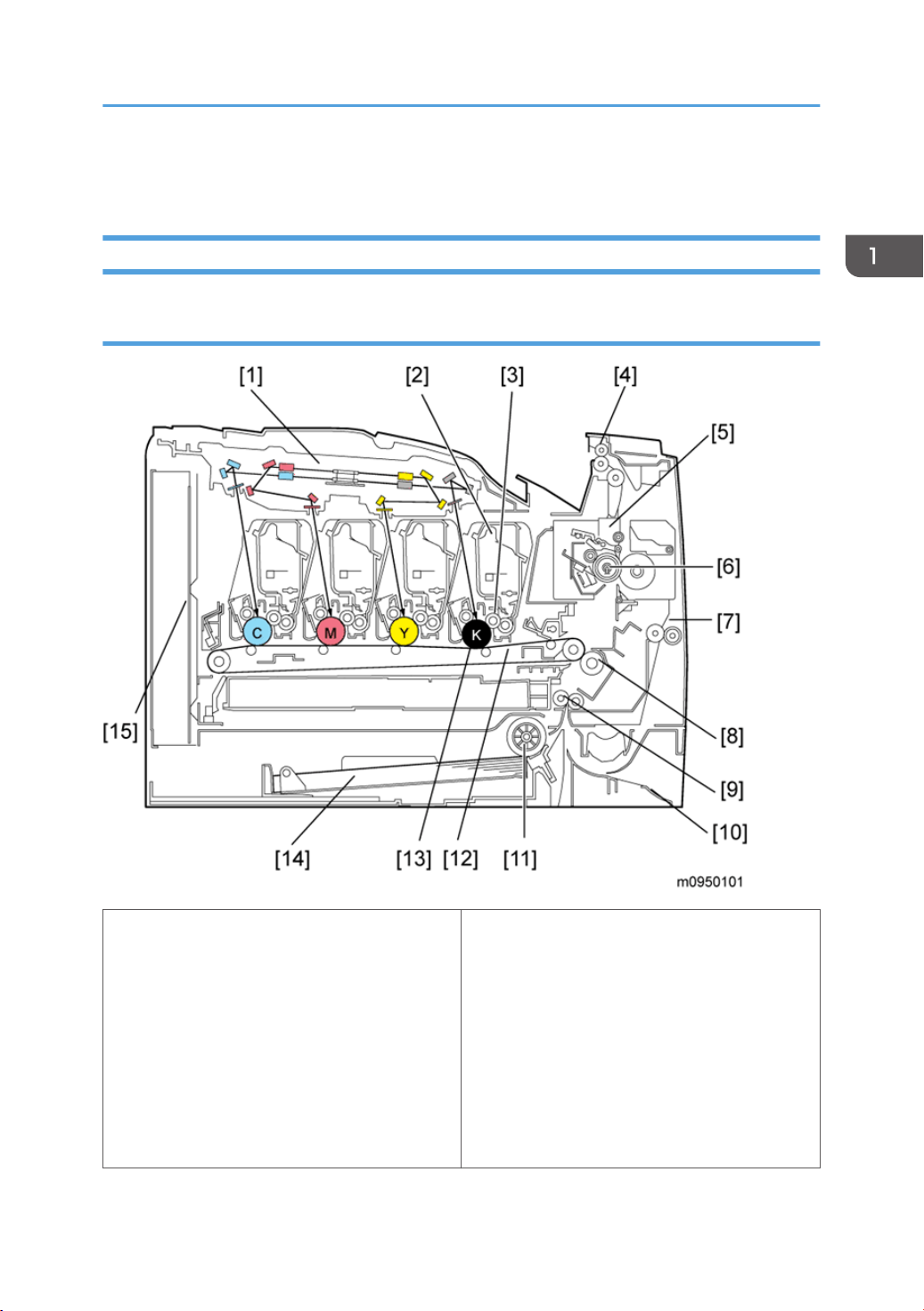
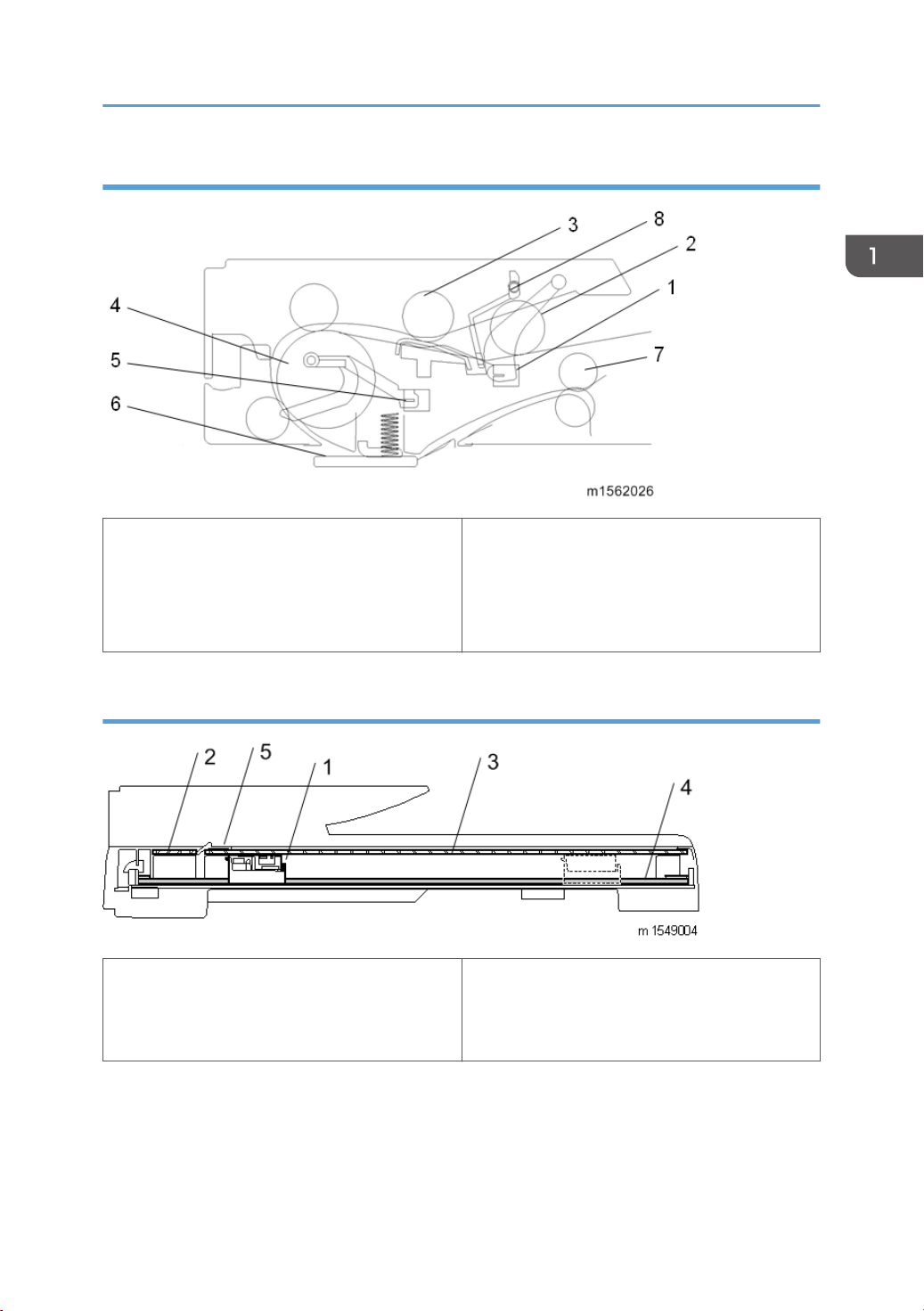
Engine (M199/M200)
Machine Overview
1. Laser Optics Housing Unit
2. Print Cartridge (AIO)
3. Development Roller (AIO)
4. Paper Exit
5. Fusing Unit
6. Fusing Lamp
7. Duplex Path
8. Transfer Roller
9. Registration Roller
10. By-pass
11. Paper Feed Roller
12. ITB (Image Transfer Belt) Unit
13. OPC (AIO)
14. Tray 1
15 EGB/Controller
13
1. Product Information
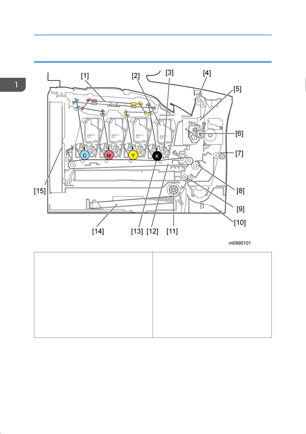
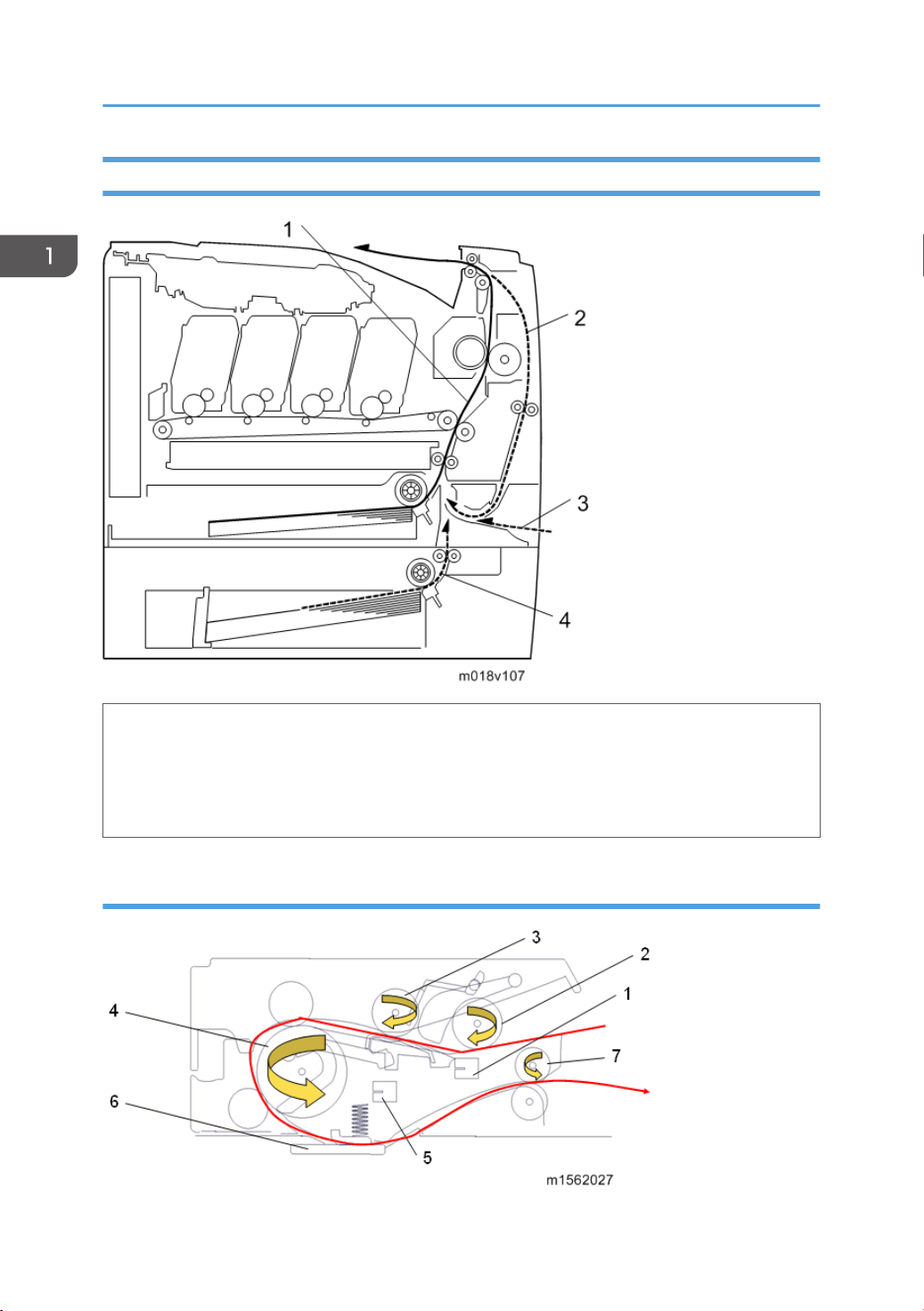
Engine (M203/M204)
14
1. Laser Optics Housing Unit
9. Registration Roller
2. Print Cartridge (AIO)
10. By-pass
3. Development Roller (AIO)
11. Paper Feed Roller
4. Paper Exit
12. ITB (Image Transfer Belt) Unit
5. Fusing Unit
13. OPC (AIO)
6. Fusing Lamp
14. Tray 1
7. Duplex Path
15 EGB/Controller
8. Transfer Roller
ADF (only for M203/M204)
Machine Overview
1. Document Sensor
2. Pick Roller
3. Separation Roller
4. Feed Roller
Scanner (only for M203/M204)
1. CIS Carriage Unit
2. DF Exposure Glass
3. Scanner Exposure Glass
5. Feed Sensor
6. DF Exposure Glass
7. Output Roller
8. Media Stopper
4. Carriage Drive Shaft
5. White Sheet
15
1. Product Information
Paper Path
1. Paper path from tray 1
2. Duplex path
3. By-pass tray
4. Paper path from tray 2 (optional)
ADF (only for M203/M204)
16
Machine Overview
1. Document sensor
2. Pick roller
3. Separation roller
4. Feed roller
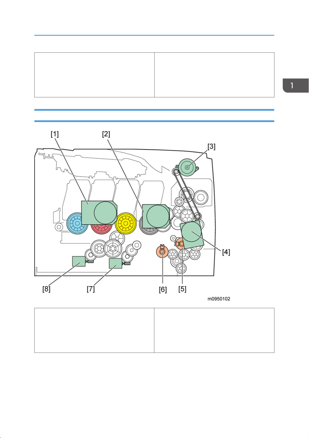
Drive Layout
5. Feed sensor
6. DF exposure glass
7. Output roller
1. Color AIO Motor
2. Black AIO Motor
3. Duplex Motor
4. Transport/Fusing Motor
• Color AIO Motor:
This drives the color AIOs (Cyan, Magenta and Yellow)
• Black AIO Motor:
This drives the black AIO and the ITB (Image Transfer Belt).
5. Registration Clutch
6. Paper Feed Clutch
7. Agitator Motor
8. ITB (Image Transfer Belt) Contact Motor
17

1. Product Information
• Duplex Motor :
This drives the paper exit roller and the duplex roller.
• Transport/Fusing Motor:
This drives the fusing unit, paper feed roller, registration roller and paper exit roller via the paper
feed clutch, registration clutch and gears.
• Registration Clutch:
This transfers drive from the transport/ fusing motor to the registration roller.
• Paper Feed Clutch:
This transfers drive from the transport/ fusing motor to the paper feed roller.
• Agitator Motor:
This moves the agitators in the waste toner bottle.
• ITB Contact Motor:
This moves the ITB into contact with and away from the color OPCs.
18

Machine Configuration
Machine Configuration
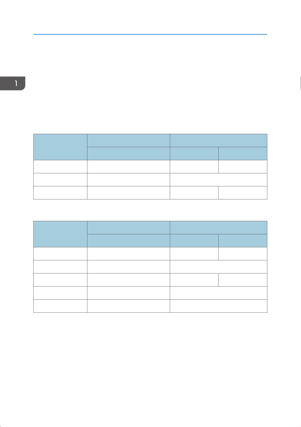
Printer Model (M199/M200)
Duplex Unit Optional Memory Optional Tray (G849) PCL/ PS
Auto N 500 x 1 Y
MF Model (M203/M204)
Duplex Unit Optional Memory Optional Tray (G849) PCL/ PS Fax
Auto N 500 x 1 Y Y
19
1. Product Information
Guidance for Those Who are Familiar with Predecessor Products
The M199/M200 series models are similar to the M095/M096 series, and the M203/M204 series
models are similar to the M099/M100 series. If you have experience with those products, the following
information will be of help when you read this manual.
Different Points from Previous Products
Printer Models:
New Previous
M199/M200 M095 M096
PPM 20ppm 16ppm 20ppm
Wireless LAN Standard N/A
PDL PCL/PS GDI PCL/PS
MF Models:
New Previous
M203/M204 M099 M100
PPM 20ppm 16ppm 20ppm
Wireless LAN Standard N/A
PDL PCL/PS GDI PCL/PS
Scanner CIS (3 channel) CCD
1st copy 20sec. 30sec.
20
2. Installation
Installation Requirements
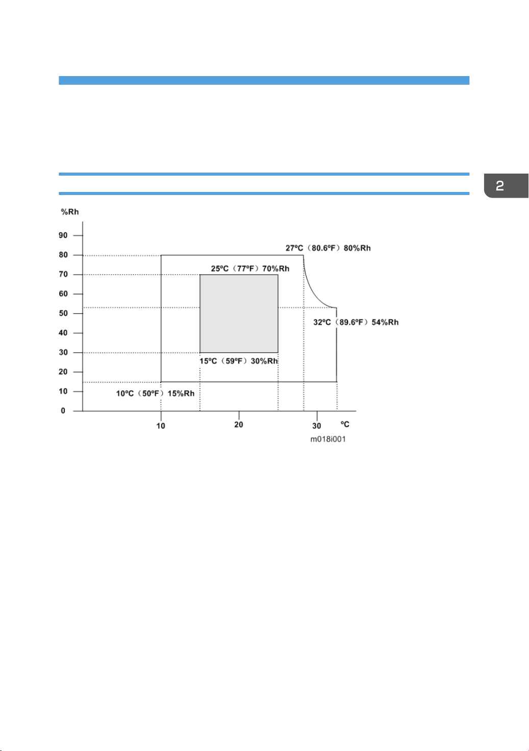
Environment
1. Temperature Range: 10°C to 32°C (50°F to 89.6°F)
2. Humidity Range: 15% to 80% RH
3.
Ambient Illumination: Less than 2,000 lux (do not expose to direct sunlight)
4. Ventilation: 30 m3 /hr/person
5. Do not put the machine in areas that get sudden temperature changes. This includes:
• Areas directly exposed to cool air from an air conditioner
• Areas directly exposed to heat from a heater.
6. Do not put the machine in areas that get exposed to corrosive gas.
7. Do not install the machine at locations over 2,500 m (8,202 ft.) above sea level.
For Chinese model: 2,000 m (6,561 ft.)
8. Put the machine on a strong, level base. (Inclination on any side must be no more than 3 mm.)
9. Do not put the machine in areas with strong vibrations.
21
2. Installation
Machine level
Front to back: Within 3 mm (0.12") of level
Right to left: Within 3 mm (0.12") of level
Machine Space Requirements
Put the machine near the power source with these clearances:
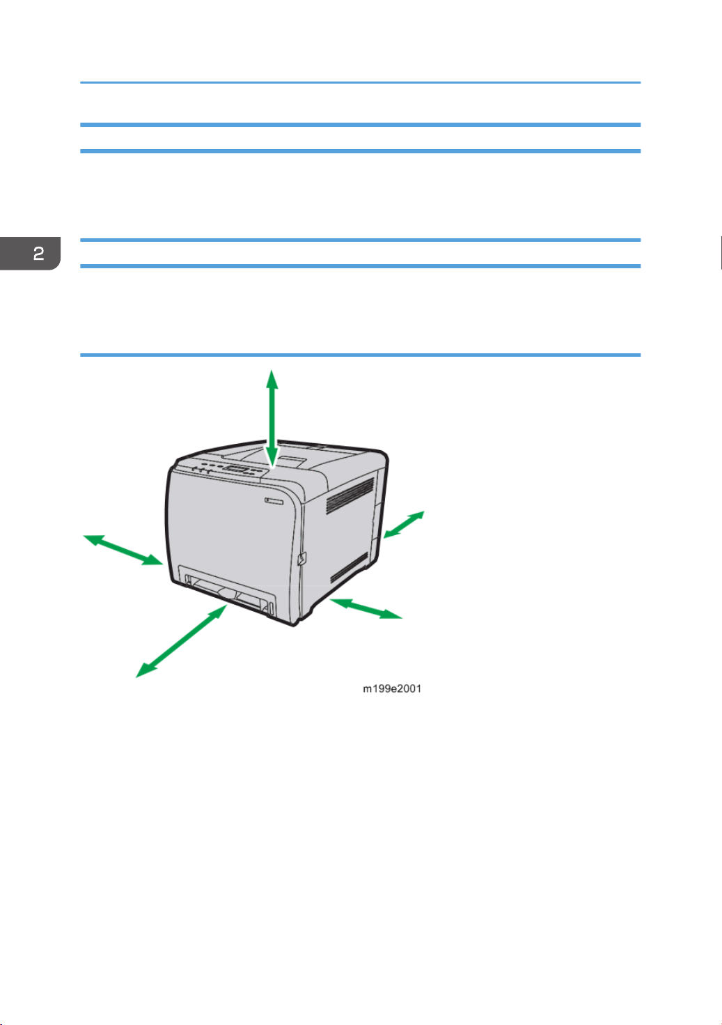
Printer Models (M199/M200)
Left side: Over 20 cm (7.9")
Rear: Over 10 cm (4")
Right side: Over 10 cm (4")
Front: Over 70 cm (27.6")
Top: Over 33 cm (13")
22
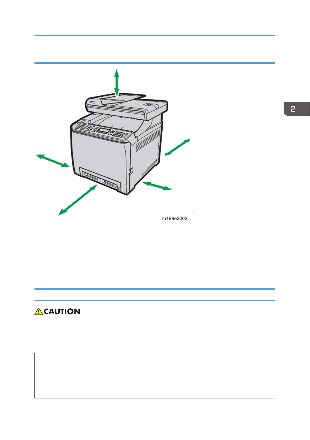
MF Models (M203/M204)
Installation Requirements
Left side: Over 20 cm (7.9")
Rear: Over 20 cm (7.9")
Right side: Over 10 cm (4")
Front: Over 70 cm (27.6")
Top: Over 24 cm (9.5")
Power Requirements
• Make sure that the plug is tightly in the outlet.
• Avoid multi-wiring.
• Make sure that you ground the machine.
120 V to 127 V, 60 Hz: Less than 11 A (for North America)
Input voltage level
Permitted voltage fluctuation: 10%
220 V to 240 V, 50 Hz/60 Hz: Less than 6 A (for Europe/ Asia)
110 V, 60 Hz: Less than 12 A (for Taiwan)
23

2. Installation
Do not set anything on the power cord.
Installation Procedure
Refer to the Quick Installation Guide for details about installing the machine.
24

3. Preventive Maintenance
Preventive Maintenance
See "Appendices" for the "User Replaceable Items".
25

3. Preventive Maintenance
26

4. Replacement and Adjustment
Before You Start
General Precautions
• If there are printer jobs in the machine, print out all jobs in the printer buffer.
• Turn off the main power switch and unplug the machine before you do the procedures in this
section.
Use extreme caution when removing and replacing components. The cables in the machine are located
very close to moving parts; proper routing is a must.
After components have been removed, any cables that have been displaced during the procedure must
be restored as close as possible to their original positions. Before removing any component from the
machine, note any cable routings that may be affected.
Before servicing the machine:
1. Verify that documents are not stored in memory.
2. Remove the print cartridge before you remove parts.
3. Unplug the power cord.
4. Work on a flat and clean surface.
5. Replace with authorized components only.
6. Do not force plastic material components.
Make sure all components are returned to their original positions.
AIO
The AIO consists of the OPC drum, charge roller, development unit, cleaning components and toner
tank. Observe the following precautions when handling the AIO.
1. Never touch the drum surface with bare hands. If the drum surface is dirty or if you have
accidentally touched it, wipe it with a dry cloth, or clean it with wet cotton and then wipe it dry with
a cloth.
2. Never use alcohol to clean the drum. Alcohol will dissolve the drum surface.
3. Store the AIO in a cool dry place.
4. Do not expose the drum to corrosive gases (ammonia, etc.).
5. Do not shake a used AIO, as this may cause toner to spill out.
27

4. Replacement and Adjustment
6. Dispose of used AIO components in accordance with local regulations.
Laser Unit
1. Do not loosen or adjust the screws securing the LD drive board on the LD unit. Doing so will throw
the LD unit out of adjustment.
2. Do not adjust the variable resistors on the LD unit, as these are permanently adjusted at the factory.
If replacement of the LD drive board is necessary, replace the entire LD unit.
Keep the polygon mirror and toroidal lens free of dust. Laser performance is very sensitive to dust
3.
on these components.
4. Do not touch the shield glass or the surface of the polygon mirror with bare hands.
5. Do not adjust the Laser Synchronization detector on the LD unit, as these are permanently adjusted
at the factory.
Transfer Roller
1. Never touch the surface of the transfer roller with bare hands.
2. Be careful not to scratch the transfer roller, as the surface is easily damaged.
Fusing
1. After installing the fusing thermistor, make sure that it is in contact with the hot roller and that the
roller can rotate freely.
2. Be careful to avoid damage to the hot roller stripper pawls and their tension springs.
Do not touch the fusing lamp and rollers with bare hands.
3.
4. Make sure that the fusing lamp is positioned correctly and that it does not touch the inner surface of
the hot roller.
Paper Feed
1. Do not touch the surface of paper feed rollers.
2. To avoid misfeeds, the side and end fences in each paper tray must be positioned correctly so as to
align with loaded paper size.
Scanner Unit (for M203/M204)
1. Clean the parts indicated by arrows with a soft damp cloth and then wipe the same parts with a dry
cloth to remove any remaining moisture.
28
 Loading...