

Ricoh MET-C1 Field Service Manual

Model MET-C1
Machine Code: D176/D177
Field Service Manual
September, 2013
Subject to change


Important Safety Notices
Prevention of Physical Injury
1. Before disassembling or assembling parts of the copier and peripherals, make sure that the copier
power cord is unplugged.
2. The wall outlet should be near the copier and easily accessible.
3. If any adjustment or operation check has to be made with exterior covers off or open while the
main switch is turned on, keep hands away from electrified or mechanically driven components.
4. The copier drives some of its components when it completes the warm-up period. Be careful to
keep hands away from the mechanical and electrical components as the copier starts operation.
5. The inside and the metal parts of the fusing unit become extremely hot while the copier is operating.
Be careful to avoid touching those components with your bare hands.
Health Safety Conditions
1. Toner and developer are non-toxic, but if you get either of them in your eyes by accident, it may
cause temporary eye discomfort. Immediately wash eyes with plenty of water. If unsuccessful, get
medical attention.
2. The copier, which use high voltage power source, can generate ozone gas. High ozone density is
harmful to human health. Therefore, the machine must be installed in a well-ventilated room.
Observance of Electrical Safety Standards
The copier and its peripherals must be serviced by a customer service representative who has completed
the training course on those models.
• Keep the machine away from flammable liquids, gases, and aerosols. A fire or an explosion might
occur.
• The Controller board on this machine contains a lithium battery. The danger of explosion exists if a
battery of this type is incorrectly replaced. Replace only with the same or an equivalent type
recommended by the manufacturer. Discard batteries in accordance with the manufacturer's
instructions and local regulations.
• The optional fax and memory expansion units contain lithium batteries, which can explode if
replaced incorrectly. Replace only with the same or an equivalent type recommended by the
1

manufacturer. Do not recharge or burn the batteries. Used batteries must be handled in
accordance with local regulations.
Safety and Ecological Notes for Disposal
1. Do not incinerate toner bottles or used toner. Toner dust may ignite suddenly when exposed to an
open flame.
2. Dispose of used toner, the maintenance unit which includes developer or the organic
photoconductor in accordance with local regulations. (These are non-toxic supplies.)
3. Dispose of replaced parts in accordance with local regulations.
4. When keeping used lithium batteries in order to dispose of them later, do not put more than 100
batteries per sealed box. Storing larger numbers or not sealing them apart may lead to chemical
reactions and heat build-up.
Laser Safety
The Center for Devices and Radiological Health (CDRH) prohibits the repair of laser-based optical units
in the field. The optical housing unit can only be repaired in a factory or at a location with the requisite
equipment. The laser subsystem is replaceable in the field by a qualified Customer Engineer. The laser
chassis is not repairable in the field. Customer engineers are therefore directed to return all chassis and
laser subsystems to the factory or service depot when replacement of the optical subsystem is required.
• Use of controls, or adjustment, or performance of procedures other than those specified in this
manual may result in hazardous radiation exposure.
• Turn off the main switch before attempting any of the procedures in the Laser Optics Housing Unit
section. Laser beams can seriously damage your eyes.
CAUTION MARKING:
Warnings, Cautions, Notes
In this manual, the following important symbols and notations are used.
2

• A Warning indicates a potentially hazardous situation. Failure to obey a Warning could result in
death or serious injury.
• A Caution indicates a potentially hazardous situation. Failure to obey a Caution could result in
minor or moderate injury or damage to the machine or other property.
• Obey these guidelines to avoid problems such as misfeeds, damage to originals, loss of valuable
data and to prevent damage to the machine.
• This information provides tips and advice about how to best service the machine.
3
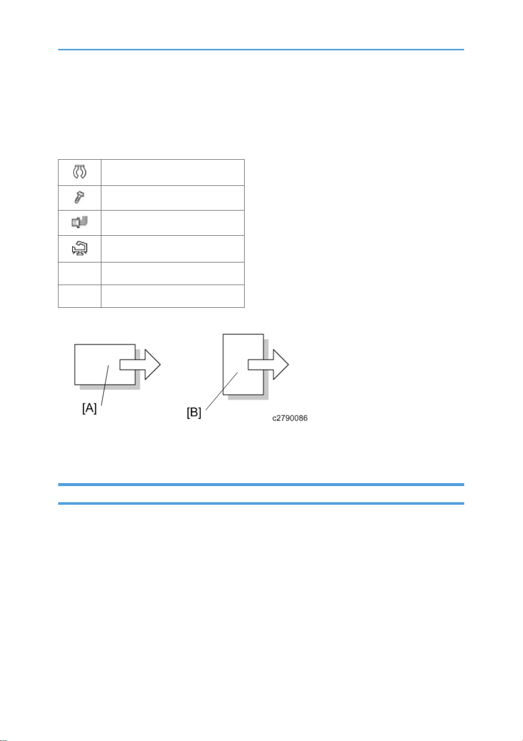
Symbols, Abbreviations and Trademarks
This manual uses several symbols and abbreviations. The meaning of those symbols and abbreviations
are as follows:
Clip ring
Screw
Connector
Clamp
SEF Short Edge Feed
LEF Long Edge Feed
[A] Short Edge Feed (SEF)
[B] Long Edge Feed (LEF)
Trademarks
Microsoft®, Windows®, and MS-DOS® are registered trademarks of Microsoft Corporation in the
United States and /or other countries.
PostScript® is a registered trademark of Adobe Systems, Incorporated.
PCL® is a registered trademark of Hewlett-Packard Company.
Ethernet® is a registered trademark of Xerox Corporation.
PowerPC® is a registered trademark of International Business Machines Corporation.
Other product names used herein are for identification purposes only and may be trademarks of their
respective companies. We disclaim any and all rights involved with those marks.
4

TABLE OF CONTENTS
Important Safety Notices...................................................................................................................................1
Prevention of Physical Injury..........................................................................................................................1
Health Safety Conditions...............................................................................................................................1
Observance of Electrical Safety Standards.................................................................................................1
Safety and Ecological Notes for Disposal...................................................................................................2
Laser Safety.....................................................................................................................................................2
Warnings, Cautions, Notes...........................................................................................................................2
Symbols, Abbreviations and Trademarks.........................................................................................................4
Trademarks.....................................................................................................................................................4
1. Product Information
Product Overview.............................................................................................................................................21
Component Layout.......................................................................................................................................21
Scanner Unit.................................................................................................................................................22
Laser Exposure Unit.....................................................................................................................................23
Image Transfer Unit......................................................................................................................................24
PCDU............................................................................................................................................................25
Toner Supply / Waste Toner Bottle...........................................................................................................26
Paper Feed Unit...........................................................................................................................................27
Duplex Unit...................................................................................................................................................28
By-pass unit .................................................................................................................................................29
Fusing Unit....................................................................................................................................................30
Paper Transfer / Paper Exit.........................................................................................................................31
Air Flow.........................................................................................................................................................32
Drive Unit......................................................................................................................................................33
Board / Switch............................................................................................................................................34
Paper Path....................................................................................................................................................35
Drive Layout..................................................................................................................................................37
Machine Codes and Peripherals Configuration............................................................................................39
Diagram........................................................................................................................................................39
Options................................................................................................................................................39
Specifications....................................................................................................................................................43
Guidance for Those Who are Familiar with Similar Products.......................................................................44
Differences from similar models..................................................................................................................44
5

Scan, LD unit, Paper feed unit............................................................................................................44
Duplex, Driving, Main frame.............................................................................................................44
PCDU....................................................................................................................................................45
Fusing...................................................................................................................................................46
Electrical component...........................................................................................................................46
New features of D176/D177...................................................................................................................46
Important notice for machine......................................................................................................................47
2. Installation
Installation Requirements.................................................................................................................................49
Environment..................................................................................................................................................49
Machine Space Requirements....................................................................................................................50
Machine Dimensions...................................................................................................................................51
Power Requirements....................................................................................................................................51
Input voltage level...............................................................................................................................52
Main Machine Installation...............................................................................................................................53
Important notice on security issues.............................................................................................................53
Overview.............................................................................................................................................53
Password setting procedure...............................................................................................................54
Installation Flow Chart.................................................................................................................................59
Accessory Check..........................................................................................................................................59
Installation Procedure..................................................................................................................................61
Removal of packing materials and shipping retainers / Removal of PCDU seal..........................61
Toner bottle installation.......................................................................................................................66
Attaching the optical cloth pocket.....................................................................................................67
Attaching paper output tray parts......................................................................................................68
Connecting the power cord...............................................................................................................68
Image quality test / settings........................................................................................................................69
Image quality test................................................................................................................................69
Checking the copy image with the test chart....................................................................................69
Paper setting........................................................................................................................................69
Moving the Machine...................................................................................................................................69
Paper Feed Unit PB3210.................................................................................................................................71
Accessory Check..........................................................................................................................................71
6

Installation procedure..................................................................................................................................71
Paper Feed Unit PB3150.................................................................................................................................75
Accessory Check..........................................................................................................................................75
Installation procedure..................................................................................................................................75
Caster Table Type M3.....................................................................................................................................79
Accessory Check..........................................................................................................................................79
Installation procedure..................................................................................................................................79
How to place MFP on the caster table..............................................................................................80
How to place the Paper Feed Unit PB3150 on the caster table.....................................................80
Platen Cover PN2000.....................................................................................................................................82
Accessory Check..........................................................................................................................................82
Installation Procedure..................................................................................................................................82
ARDF DF3090..................................................................................................................................................85
Accessory Check..........................................................................................................................................85
Installation Procedure..................................................................................................................................85
When feeding thin paper...................................................................................................................90
1 Bin Tray BN3110.........................................................................................................................................91
Accessory Check..........................................................................................................................................91
Installation Procedure..................................................................................................................................91
Internal Shift Tray SH3070.............................................................................................................................99
Accessory Check..........................................................................................................................................99
Installation procedure..................................................................................................................................99
Side Tray Type M3........................................................................................................................................104
Accessory Check.......................................................................................................................................104
Installation procedure...............................................................................................................................105
Internal Finisher SR3130...............................................................................................................................109
Accessory Check.......................................................................................................................................109
Installation Procedure................................................................................................................................109
Punch Unit PU3040.......................................................................................................................................120
Accessory Check.......................................................................................................................................120
Installation Procedure................................................................................................................................121
Internal Finisher SR3180...............................................................................................................................128
Accessory Check.......................................................................................................................................128
7

Installation procedure...............................................................................................................................129
Staple setting as an initial setting.....................................................................................................140
Anti-Condensation Heater............................................................................................................................142
Anti-Condensation Heater (Scanner)......................................................................................................142
Accessory Check..............................................................................................................................142
Installation procedure.......................................................................................................................143
Anti-Condensation Heater (PCDU)..........................................................................................................148
Accessory Check..............................................................................................................................148
Installation procedure.......................................................................................................................149
Key Counter Bracket Type M3.....................................................................................................................155
Accessory Check.......................................................................................................................................155
Installation procedure...............................................................................................................................155
Optional Counter Interface Unit Type A......................................................................................................158
Accessory Check.......................................................................................................................................158
Installation procedure...............................................................................................................................158
Key Counter......................................................................................................................................158
Smart Card Reader Built-in Unit Type M2 (D739-36)...............................................................................160
Accessory Check.......................................................................................................................................160
Installation Procedure................................................................................................................................160
Imageable Area Extension Unit Type M3...................................................................................................166
Accessory Check.......................................................................................................................................166
Installation Procedure................................................................................................................................166
When you forgot to change the SP.................................................................................................167
Internal Options.............................................................................................................................................168
List of Slots..................................................................................................................................................168
IEEE 802.11a/g/n Interface Unit Type M2...............................................................................................170
Accessory Check.......................................................................................................................................170
Installation procedure...............................................................................................................................170
Attaching the boards........................................................................................................................171
Attaching the antenna......................................................................................................................171
Settings.......................................................................................................................................................172
Check the connection of the wireless LAN interface......................................................................172
IEEE 1284 Interface Board Type A..............................................................................................................174
8

Accessory Check.......................................................................................................................................174
Installation procedure...............................................................................................................................174
File Format Converter Type E........................................................................................................................176
Accessory Check.......................................................................................................................................176
Installation procedure...............................................................................................................................176
Copy Data Security Unit Type G..................................................................................................................178
Accessory Check.......................................................................................................................................178
Installation procedure...............................................................................................................................178
Settings (to be done by the user)..............................................................................................................179
Equipment administrator settings.....................................................................................................179
Bluetooth Interface Unit Type D....................................................................................................................180
Accessory Check.......................................................................................................................................180
Installation procedure...............................................................................................................................180
SD Card Option.............................................................................................................................................182
SD Card Slots............................................................................................................................................182
List of Slots Used........................................................................................................................................182
SD Card Appli Move....................................................................................................................................184
Overview....................................................................................................................................................184
Move Exec.................................................................................................................................................185
Undo Exec..................................................................................................................................................187
Data Overwrite Security Unit Type H (D377).............................................................................................189
Overview....................................................................................................................................................189
Component List..........................................................................................................................................189
Before You Begin the Procedure..............................................................................................................189
Seal Check and Removal.................................................................................................................190
Installation Procedure................................................................................................................................191
Camera Direct Print Card Type M3.............................................................................................................192
Accessory Check.......................................................................................................................................192
Installation procedure...............................................................................................................................192
Browser Unit Type M9..................................................................................................................................194
Accessory Check.......................................................................................................................................194
Installation procedure...............................................................................................................................194
Settings.......................................................................................................................................................196
9

Browser default setting.....................................................................................................................196
SD card for NetWare printing Type M3.....................................................................................................197
Accessory Check.......................................................................................................................................197
Installation procedure...............................................................................................................................197
OCR Unit Type M2........................................................................................................................................199
Accessory Check.......................................................................................................................................199
Searchable PDF function outline..............................................................................................................199
Installation procedure...............................................................................................................................199
Postscript3 Unit Type M3..............................................................................................................................202
Accessory Check.......................................................................................................................................202
Installation procedure...............................................................................................................................202
Security Function Installation.........................................................................................................................204
Data Overwrite Security...........................................................................................................................205
Before You Begin the Procedure.....................................................................................................205
Installation Procedure.......................................................................................................................205
HDD Encryption.........................................................................................................................................206
Before You Begin the Procedure.....................................................................................................206
Enable Encryption Setting................................................................................................................207
Check the Encryption Settings..........................................................................................................210
Print the encryption key....................................................................................................................211
Memory Unit Type M3 2GB.........................................................................................................................213
Accessory Check.......................................................................................................................................213
Installation Procedure................................................................................................................................213
3. Preventive Maintenance
PM Parts Settings............................................................................................................................................215
Replacement procedure of the PM parts.................................................................................................215
After installing the new PM parts..............................................................................................................216
Preparation before operation check........................................................................................................216
Operation check........................................................................................................................................217
4. Replacement and Adjustment
Notes on the Main Power Switch.................................................................................................................219
Push Switch................................................................................................................................................219
Characteristics of the Push Switch (DC Switch)..............................................................................219
10

Shutdown Method............................................................................................................................220
Forced Shutdown..............................................................................................................................220
Beforehand.....................................................................................................................................................222
Special Tools..................................................................................................................................................223
Exterior Covers...............................................................................................................................................224
Front Cover................................................................................................................................................224
Controller Cover........................................................................................................................................226
Upper Left Cover.......................................................................................................................................226
Left Rear Cover..........................................................................................................................................227
Left Cover...................................................................................................................................................227
Rear Cover.................................................................................................................................................230
Rear Right Cover.......................................................................................................................................231
Rear Lower Cover......................................................................................................................................231
Scanner Rear Cover..................................................................................................................................232
Scanner Rear Cover (Small).....................................................................................................................232
Right Rear Cover.......................................................................................................................................232
Right Upper Cover ...................................................................................................................................233
Main power switch cover.........................................................................................................................234
Waste Toner Cover...................................................................................................................................234
Reverse Tray..............................................................................................................................................235
Paper Exit Tray...........................................................................................................................................236
Paper Exit Cover........................................................................................................................................236
Paper Exit Lower Cover.............................................................................................................................236
Paper Exit Front Cover..............................................................................................................................237
Inner Upper Cover....................................................................................................................................238
Inner Lower Cover.....................................................................................................................................239
Operation Panel Unit.....................................................................................................................................240
Operation Panel........................................................................................................................................240
Board A......................................................................................................................................................241
Board B......................................................................................................................................................243
Board C......................................................................................................................................................244
LCD Panel...................................................................................................................................................244
LCD.............................................................................................................................................................245
11

Notes when replacing the LCD........................................................................................................245
Replacement procedure...................................................................................................................248
Scanner Unit...................................................................................................................................................250
Scanner Exterior........................................................................................................................................250
Scanner Upper Cover......................................................................................................................250
Scanner Right Cover.........................................................................................................................250
Scanner Front Cover.........................................................................................................................251
Scanner Left Cover...........................................................................................................................251
Exposure Glass..........................................................................................................................................252
Exposure Lamp (LED)................................................................................................................................254
Scanner Motor...........................................................................................................................................255
Lens Block...................................................................................................................................................258
Original Size Sensor.................................................................................................................................258
SIO.............................................................................................................................................................259
Scanner HP Sensor....................................................................................................................................260
DF Position Sensor.....................................................................................................................................261
Adjusting the Scanner Wire......................................................................................................................262
Scanner Wire (Front)........................................................................................................................262
Scanner wire assembly (front side).................................................................................................265
Scanner position adjustment............................................................................................................267
Scanner Wire (Rear)........................................................................................................................268
Scanner Wire Assembly (rear side)................................................................................................271
Modifying the Scanner (contact/contactless) when using ARDF..........................................................272
Procedure for the ADF......................................................................................................................272
Procedure for the scanner................................................................................................................275
Laser Unit........................................................................................................................................................276
Laser Unit....................................................................................................................................................276
Before Replacement.........................................................................................................................277
Removing...........................................................................................................................................277
Installing a New Laser Unit..............................................................................................................278
Adjustment after replacing the laser unit.........................................................................................279
Polygon Motor...........................................................................................................................................280
Adjustment after replacing the polygon motor...............................................................................280
12

PCDU..............................................................................................................................................................281
PCDU..........................................................................................................................................................281
Before replacing the PCDU..............................................................................................................281
Replacement......................................................................................................................................281
PCU/Development Unit............................................................................................................................283
Before replacing a PCU...................................................................................................................283
Before replacing a Development Unit.............................................................................................285
Replacement......................................................................................................................................285
Notes for assembling PCU/Development unit ..............................................................................288
Method for checking after replacement.........................................................................................288
Imaging Temperature Sensor (Thermistor)..............................................................................................289
Waste Toner...................................................................................................................................................291
Replacement..............................................................................................................................................291
Adjustment after replacing........................................................................................................................291
Image Transfer Unit.......................................................................................................................................293
Image Transfer Belt Unit............................................................................................................................293
Adjustment before replacing the image transfer belt unit..............................................................294
Replacement......................................................................................................................................294
Image Transfer Cleaning Unit...................................................................................................................297
Adjustment before replacing the image transfer cleaning unit......................................................298
Replacement......................................................................................................................................298
Image Transfer Belt....................................................................................................................................301
Replacement......................................................................................................................................301
Adjustment after replacing the Image transfer belt........................................................................304
Paper Transfer Roller.................................................................................................................................305
Paper Transfer Roller Unit ........................................................................................................................305
Adjustment before replacing the paper transfer roller unit............................................................305
Replacement......................................................................................................................................305
Fusing Entrance Sensor.............................................................................................................................307
TM (ID) Sensor...........................................................................................................................................308
Before Replacing the TM(ID) sensor...............................................................................................308
Replacement procedure...................................................................................................................310
Adjustment after replacing the TM(ID) sensor................................................................................311
13

Temperature and Humidity Sensor..........................................................................................................312
ITB Contact and Release Sensor..............................................................................................................313
Drive Unit........................................................................................................................................................315
Overview....................................................................................................................................................315
Paper Feed Motor.....................................................................................................................................316
Transport Motor.........................................................................................................................................316
Transfer Motor Unit...................................................................................................................................317
Imaging Drive Unit....................................................................................................................................318
PCU Motor: CMY......................................................................................................................................320
Development Motor: CMY.......................................................................................................................320
Development solenoid..............................................................................................................................320
Fusing Motor..............................................................................................................................................322
Paper Exit / Pressure Release Motor.......................................................................................................322
Duplex Entrance Motor.............................................................................................................................323
Toner Transport Motor..............................................................................................................................324
Sub Hopper...............................................................................................................................................325
K.........................................................................................................................................................325
C.........................................................................................................................................................325
M........................................................................................................................................................327
Y.........................................................................................................................................................328
Toner End Sensor......................................................................................................................................329
Toner Bottle Drive Motor..........................................................................................................................330
K.........................................................................................................................................................330
C.........................................................................................................................................................330
M........................................................................................................................................................331
Y.........................................................................................................................................................331
ID Chip.......................................................................................................................................................331
K.........................................................................................................................................................331
C.........................................................................................................................................................332
M........................................................................................................................................................332
Y.........................................................................................................................................................333
Transport screw.........................................................................................................................................334
Y.........................................................................................................................................................334
14

M........................................................................................................................................................337
C.........................................................................................................................................................338
K.........................................................................................................................................................338
Fusing Unit......................................................................................................................................................340
Fusing Unit..................................................................................................................................................340
Adjustment before replacing the fusing unit....................................................................................340
Replacement......................................................................................................................................340
Fusing Entrance Guide Plate.....................................................................................................................341
Replacement......................................................................................................................................341
Cleaning the Fusing Entrance Guide Plate.....................................................................................342
Fusing Exit Guide Plate.............................................................................................................................342
Replacement......................................................................................................................................342
Cleaning the Fusing Exit Guide Plate..............................................................................................343
Fusing Upper Cover..................................................................................................................................344
Fusing Lower Cover...................................................................................................................................344
Fusing Front Cover.....................................................................................................................................345
Fusing Rear Cover.....................................................................................................................................346
Heating sleeve unit....................................................................................................................................347
Replacement......................................................................................................................................347
How to cancel SC544-02/SC554-02 with a new unit detection fuse.......................................350
Pressure Roller............................................................................................................................................351
Adjustment before replacing the pressure roller............................................................................351
Replacement......................................................................................................................................351
Thermostat Unit..........................................................................................................................................353
Non-contact Thermistor Unit.....................................................................................................................354
Fusing Thermistor.......................................................................................................................................355
Fusing Thermopile Unit..............................................................................................................................355
Pressure Roller HP Sensor.........................................................................................................................356
Fusing Shield Position Sensor...................................................................................................................356
Fusing Shield Drive Motor........................................................................................................................357
Paper Exit........................................................................................................................................................359
Paper Exit Unit...........................................................................................................................................359
Paper Exit Switching Solenoid..................................................................................................................359
15

Paper Exit Sensor.......................................................................................................................................360
Reverse Sensor..........................................................................................................................................362
Reverse Motor...........................................................................................................................................363
Fusing Exit Sensor......................................................................................................................................364
Paper Feed.....................................................................................................................................................366
Paper Feed Unit.........................................................................................................................................366
1st Paper Feed Unit..........................................................................................................................366
2nd Paper Feed Unit........................................................................................................................367
Paper Dust Collection Unit........................................................................................................................369
Separation Roller, Torque Limiter.............................................................................................................370
Pick-up Roller, Paper Feed Roller.............................................................................................................371
1st Tray Lift Motor / 2nd Tray Lift Motor................................................................................................372
Vertical Transport Sensor..........................................................................................................................373
Limit Sensor................................................................................................................................................374
Paper End Sensor......................................................................................................................................375
Registration Sensor....................................................................................................................................376
By-pass Tray Unit...........................................................................................................................................377
By-pass Tray..............................................................................................................................................377
By-pass Paper End Sensor........................................................................................................................379
By-pass Pick-up Roller...............................................................................................................................380
By-pass Paper Feed Roller........................................................................................................................381
By-pass Separation Roller........................................................................................................................381
Torque Limiter.............................................................................................................................................382
Duplex Unit.....................................................................................................................................................383
Duplex Unit................................................................................................................................................383
Duplex/By-pass Motor.............................................................................................................................385
Duplex Entrance Sensor............................................................................................................................387
Duplex Exit Sensor....................................................................................................................................388
Electrical Components...................................................................................................................................391
Overview....................................................................................................................................................391
Printed Circuits/Parts Inside the Controller Box.............................................................................391
Printed Circuits Behind the Controller Box......................................................................................392
Printed Circuit/Parts Inside the Power Box.....................................................................................392
16

Printed Circuits Behind the Power Box............................................................................................393
IPU..............................................................................................................................................................393
BCU............................................................................................................................................................394
When installing the new BCU..........................................................................................................394
Replacing the NVRAM (EEPROM) on the BCU.............................................................................395
Controller Board........................................................................................................................................396
NVRAMs on the controller board...................................................................................................397
HDD............................................................................................................................................................401
Adjustment after replacement..........................................................................................................402
Imaging IOB..............................................................................................................................................402
HVP_TTS.....................................................................................................................................................403
PSU (AC Controller Board)......................................................................................................................404
PSU (DC Power)........................................................................................................................................404
Paper Transport IOB.................................................................................................................................405
HVP-CB......................................................................................................................................................406
When removing the HVP-CB together with its bracket..................................................................409
Fans/Filters.....................................................................................................................................................411
Odor Filter..................................................................................................................................................411
Development Intake Fan/Right................................................................................................................411
Development Intake Fan/Left...................................................................................................................412
Ozone Exhaust Fan...................................................................................................................................413
Paper Exit Cooling Fan.............................................................................................................................413
Fusing Exhaust Heat Fan...........................................................................................................................414
Toner Supply Cooling Fan........................................................................................................................415
PSU Cooling Fan.......................................................................................................................................416
Power Box Cooling Fan............................................................................................................................417
Image Adjustment..........................................................................................................................................418
Auto Color Calibration.............................................................................................................................418
Printer Gamma Correction........................................................................................................................418
Copy Mode.......................................................................................................................................419
Printer Mode.....................................................................................................................................423
Color Registration......................................................................................................................................424
Check the occurrence of color registration errors..........................................................................424
17

Judgment for type of color registration error..................................................................................424
Adjustment after replacing............................................................................................................................434
Image position adjustment........................................................................................................................434
Parts that require adjustment............................................................................................................434
Laser-related adjustment..................................................................................................................434
Scanner-related adjustment.............................................................................................................436
ADF image adjustment.....................................................................................................................439
5. Troubleshooting
Self-Diagnostic Mode...................................................................................................................................441
Service Call Codes....................................................................................................................................441
Service Call Conditions ...................................................................................................................441
SC logging.................................................................................................................................................442
SC automatic reboot.................................................................................................................................442
Controller self-diagnosis outline......................................................................................................445
Controller self-diagnosis flowchart..................................................................................................446
Service Call 101-195...................................................................................................................................450
SC100 (Engine: Scanning).......................................................................................................................450
Service Call 201-285...................................................................................................................................457
SC200 (Engine: Image Writing)..............................................................................................................457
Service Call 324-396...................................................................................................................................463
SC300 (Engine: Charge, Development).................................................................................................463
Service Call 441-498...................................................................................................................................468
SC400 (Engine: Around the Drum).........................................................................................................468
Service Call 501-584...................................................................................................................................474
SC500 (Engine: Paper transport 1: Paper Feed, Duplex, Transport)...................................................474
Service Call 620-689...................................................................................................................................520
SC600 (Engine: Communication and Others)........................................................................................520
SC600 (Controller)...................................................................................................................................528
Service Call 700-792...................................................................................................................................539
SC700 (Engine: Peripherals)....................................................................................................................539
Service Call 816-899...................................................................................................................................551
SC800 (Controller)...................................................................................................................................551
Service Call 900-998...................................................................................................................................612
18

SC900 (Engine: Others)...........................................................................................................................612
SC900 (Controller)...................................................................................................................................613
When SC549 is displayed...........................................................................................................................620
Troubleshooting Flowchart.......................................................................................................................620
Fusing Shield Check..................................................................................................................................621
Solution......................................................................................................................................................624
When SC670 is displayed...........................................................................................................................626
Troubleshooting Flowchart.......................................................................................................................626
Jam Detection.................................................................................................................................................627
Jam Display................................................................................................................................................627
Sensor Locations........................................................................................................................................628
Clearing a paper jam................................................................................................................................629
Paper Jam History......................................................................................................................................629
History checking method..................................................................................................................629
Paper Jam Display............................................................................................................................630
Jam Codes and Display Codes................................................................................................................630
Paper Size Code.......................................................................................................................................634
Image Quality................................................................................................................................................635
When an abnormal image is generated.................................................................................................635
Roller pitch.................................................................................................................................................636
OCR Unit Type M2........................................................................................................................................637
Recovery procedure..................................................................................................................................637
Electrical Component Defects.......................................................................................................................638
6. Environment
Environment....................................................................................................................................................641
Energy Saver Modes................................................................................................................................641
Timer Settings....................................................................................................................................642
Return to Stand-by Mode.................................................................................................................642
Recommendation..............................................................................................................................643
Energy Save Effectiveness........................................................................................................................643
19

20
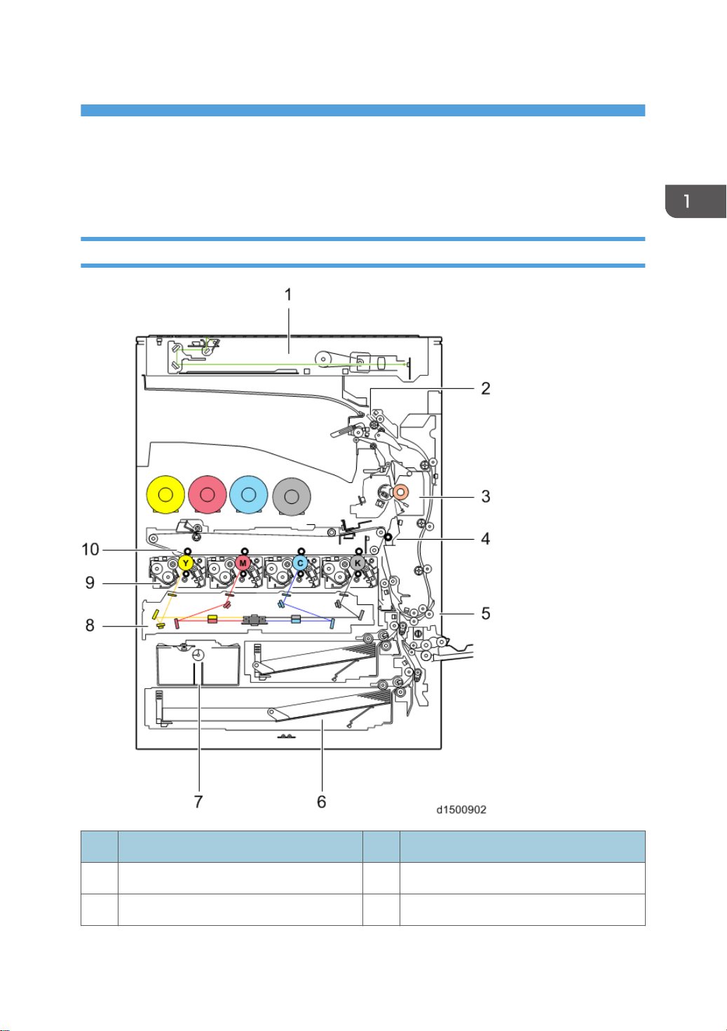
1. Product Information
Product Overview
Component Layout
No. Description No. Description
1 Scanner Unit 6 Paper Feed Unit
2 Paper Exit Unit 7 Waste Toner Unit
21

1. Product Information
No. Description No. Description
3 Fusing Unit 8 Laser Exposure Unit
4 Paper Transfer Unit 9 PCDU
5 Duplex Unit 10 Image Transfer Unit
Scanner Unit
22
No. Description No. Description
1 Operation Panel 6 Scanner Input/Output (SIO) board
2 Scanner lamp Unit (LED) 7 Scanner motor
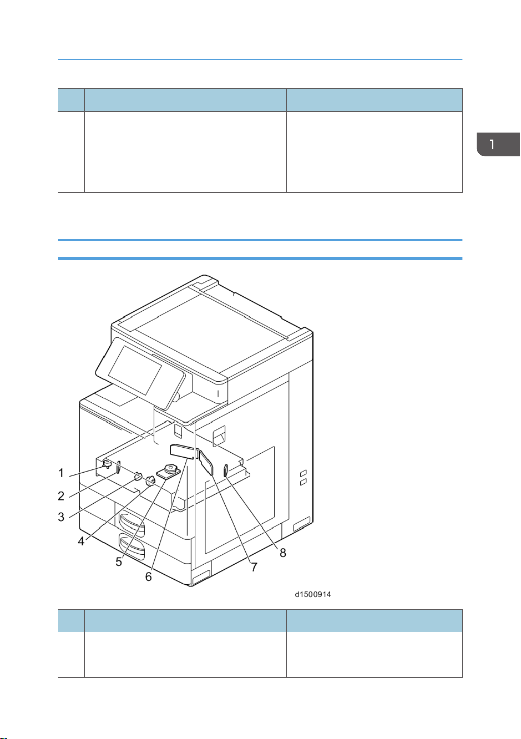
Product Overview
No. Description No. Description
3 Scanner Home Position sensor 8 Auto Paper Size detection (APS) sensor 1
Anti-condensation heater (Scanner
4
heater)
*1
9 Auto Paper Size detection (APS) sensor 2
5 DF Position Sensor 10 Sensor Board Unit (SBU)
Option
*1
Laser Exposure Unit
No. Description No. Description
1 Skew motor 5 Polygon mirror motor
2 Synchronizing detector board: M/Y-S 6 LD Drive Board (M/Y)
23
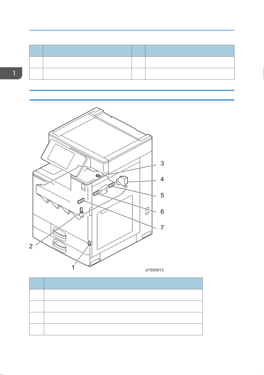
1. Product Information
No. Description No. Description
3 Skew motor 7 LD Drive Board (Bk/C)
4 Skew motor 8 Synchronizing detector board: Bk/C-S
Image Transfer Unit
24
No. Description
1 Interlock switch: Front cover (LD Safety Switch)
2 Interlock switch: Duplex Unit (LD Safety Switch)
3 ITB contact and release sensor
4 TM/P sensor shutter solenoid
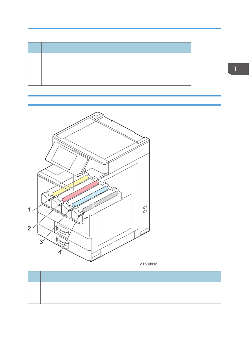
No. Description
5 TM/P sensor (rear)
6 TM/P sensor (center)
7 TM/P sensor (front)
PCDU
Product Overview
No. Description No. Description
1 PCDU (Y) 3 PCDU (C)
2 PCDU (M) 4 PCDU (Bk)
25
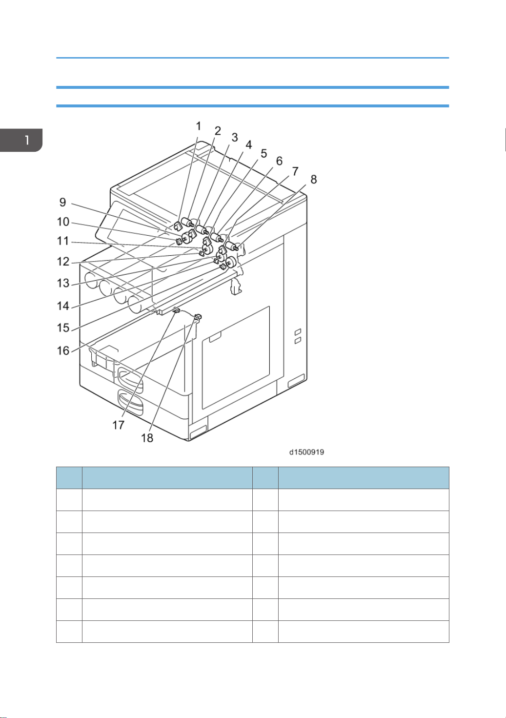
1. Product Information
Toner Supply / Waste Toner Bottle
26
No. Description No. Description
1 ID chip (Y) 10 Toner end sensor (Y)
2 Toner bottle drive motor (Y) 11 Toner transport motor (M)
3 ID chip (M) 12 Toner end sensor (M)
4 Toner bottle drive motor (M) 13 Toner transport motor (C)
5 ID chip (C) 14 Toner end sensor (C)
6 Toner bottle drive motor (C) 15 Toner end sensor (Bk)
7 ID chip (Bk) 16 Toner transport motor (Bk)

No. Description No. Description
8 Toner bottle drive motor (Bk) 17 Waste toner capacity sensor
9 Toner transport motor (Y) 18 Waste toner bottle set switch
Paper Feed Unit
Product Overview
No. Description No. Description
1 Tray set switch (1st feed tray) 10 Paper feed sensor (1st feed tray)
2 Lift motor (1st feed tray) 11 Paper end sensor (2nd feed tray)
3 Tray set switch (2nd feed tray) 12 Limit sensor (2nd feed tray)
4 Lift motor (2nd feed tray) 13 Transport sensor (1st feed tray)
5 Registration sensor 14 Paper end sensor (1st feed tray)
6 Size switch (2nd Feed Tray) 15 Limit sensor (1st feed tray)
27
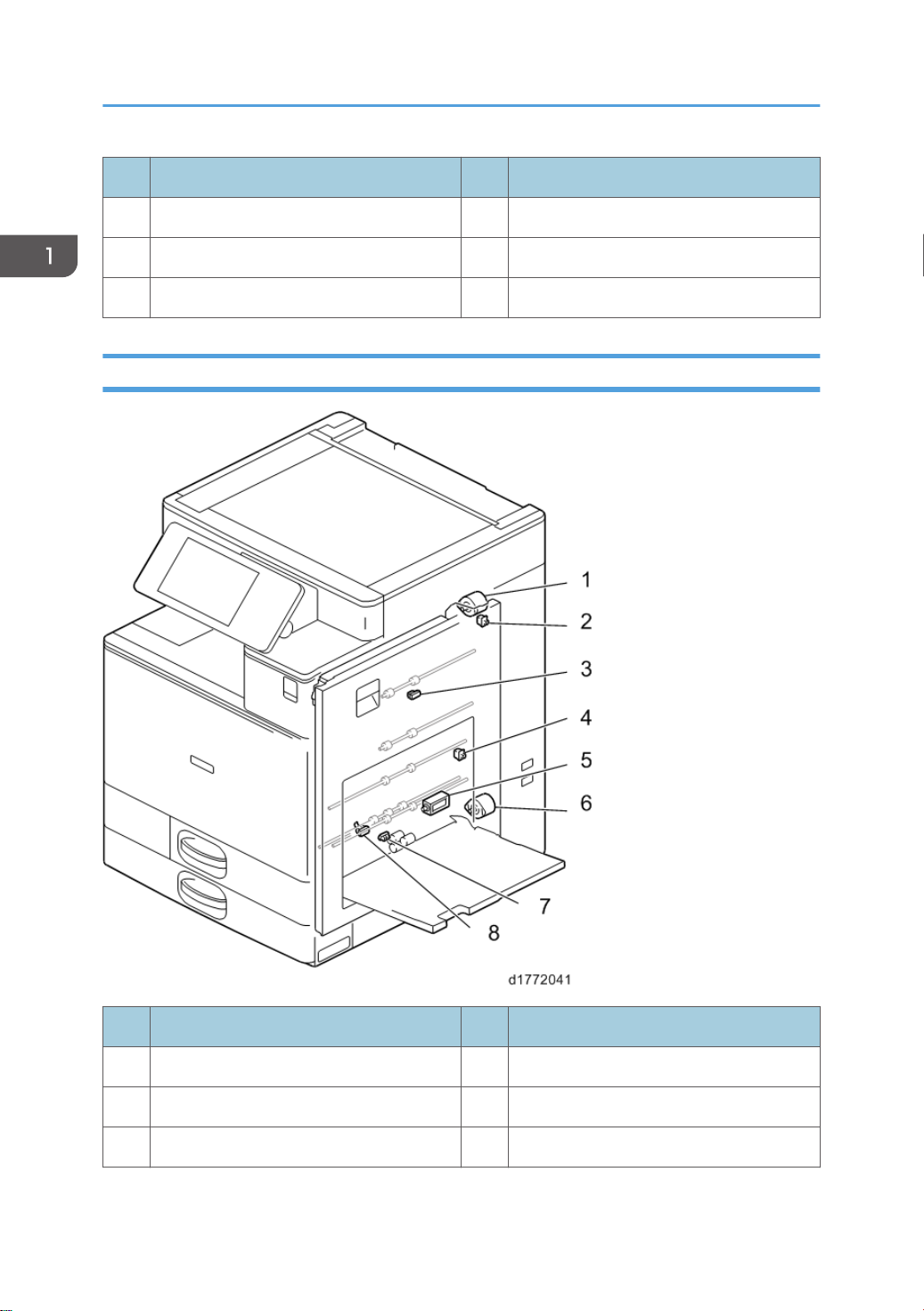
1. Product Information
No. Description No. Description
7 Anti-condensation heater 16 Pick-up solenoid (2nd feed tray)
8 Paper feed sensor (2nd Feed Tray) 17 Pick-up solenoid (1st feed tray)
9 Transport sensor (2nd Feed Tray)
Duplex Unit
28
No. Description No. Description
1 Duplex entrance motor 5 By-pass pick-up solenoid
2 Right door open/close switch 6 By-pass/Duplex motor
3 Duplex entrance sensor 7 By-pass paper end sensor
 Loading...