

Ricoh MD-P2, M075 Field Service Manual

Model MD-P2
Machine Code: M075
Field Service Manual
8 October, 2010


Safety Notices
Important Safety Notices
Prevention of Physical Injury
1. Before disassembling or assembling parts of the printer and peripherals, make sure that the printer
power cord is unplugged.
The wall outlet should be near the printer and easily accessible.
2.
3. If any adjustment or operation check has to be made with exterior covers off or open while the
main switch is turned on, keep hands away from electrified or mechanically driven components.
4. The printer drives some of its components when it completes the warm-up period. Be careful to
keep hands away from the mechanical and electrical components as the printer starts operation.
5. The inside and the metal parts of the fusing unit become extremely hot while the printer is operating.
Be careful to avoid touching those components with your bare hands.
Health Safety Conditions
Toner is non-toxic, but if you get either of them in your eyes by accident, it may cause temporary eye
discomfort. Try to remove with eye drops or flush with water as first aid. If unsuccessful, get medical
attention.
Observance of Electrical Safety Standards
The printer and its peripherals must be serviced by a customer service representative who has completed
the training course on those models.
Safety and Ecological Notes for Disposal
1. Do not incinerate toner bottles or used toner. Toner dust may ignite suddenly when exposed to an
open flame.
Dispose of used toner, the maintenance unit which includes developer or the organic
2.
photoconductor in accordance with local regulations. (These are non-toxic supplies.)
3. Dispose of replaced parts in accordance with local regulations.
• To prevent a fire or explosion, keep the machine away from flammable liquids, gases, and
aerosols. A fire or an explosion might occur.
1

Laser Safety
The Center for Devices and Radiological Health (CDRH) prohibits the repair of laser-based optical units
in the field. The optical housing unit can only be repaired in a factory or at a location with the requisite
equipment. The laser subsystem is replaceable in the field by a qualified Customer Engineer. The laser
chassis is not repairable in the field. Customer engineers are therefore directed to return all chassis and
laser subsystems to the factory or service depot when replacement of the optical subsystem is required.
• Use of controls, or adjustment, or performance of procedures other than those specified in this
manual may result in hazardous radiation exposure.
WARNING
WARNING:
Turn off the main switch before attempting any of the procedures in the Laser Optics Housing Unit
section. Laser beams can seriously damage your eyes.
CAUTION MARKING:
2
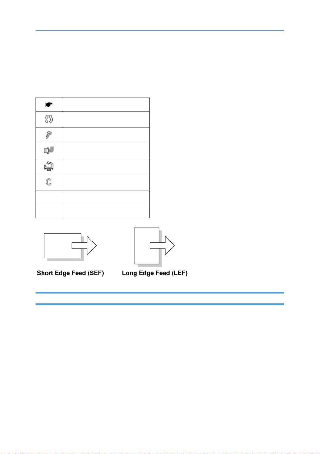
Symbols, Abbreviations and Trademarks
This manual uses several symbols and abbreviations. The meaning of those symbols and abbreviations
are as follows:
See or Refer to
Clip ring
Screw
Connector
Clamp
E-ring
SEF Short Edge Feed
LEF Long Edge Feed
Trademarks
Microsoft®, Windows®, and MS-DOS® are registered trademarks of Microsoft Corporation in the
United States and /or other countries.
PostScript® is a registered trademark of Adobe Systems, Incorporated.
PCL® is a registered trademark of Hewlett-Packard Company.
Ethernet® is a registered trademark of Xerox Corporation.
PowerPC® is a registered trademark of International Business Machines Corporation.
Other product names used herein are for identification purposes only and may be trademarks of their
respective companies. We disclaim any and all rights involved with those marks.
3

TABLE OF CONTENTS
Safety Notices.....................................................................................................................................................1
Important Safety Notices...............................................................................................................................1
Laser Safety.....................................................................................................................................................2
Symbols, Abbreviations and Trademarks.........................................................................................................3
Trademarks.....................................................................................................................................................3
1. Product Information
Specifications......................................................................................................................................................9
Machine Overview..........................................................................................................................................10
Component Layout.......................................................................................................................................10
Paper Path....................................................................................................................................................11
Drive Layout..................................................................................................................................................12
Machine Configuration....................................................................................................................................14
Mainframe (M075) and Option................................................................................................................14
Controller Options.......................................................................................................................................14
Guidance for Those Who are Familiar with Predecessor Products..............................................................16
2. Installation
Installation Requirements.................................................................................................................................17
Environment..................................................................................................................................................17
Machine level...............................................................................................................................................18
Machine Space Requirement.....................................................................................................................18
Power Requirements....................................................................................................................................18
Installation Procedure..................................................................................................................................19
3. Preventive Maintenance
Preventive Maintenance..................................................................................................................................21
4. Replacement and Adjustment
Before You Start...............................................................................................................................................23
Special Tool......................................................................................................................................................24
Exterior Covers.................................................................................................................................................25
Rear Cover...................................................................................................................................................25
Operation Panel...........................................................................................................................................26
Right Cover...................................................................................................................................................27
Left Cover......................................................................................................................................................27
Front Cover Unit...........................................................................................................................................28
4

Laser Optics......................................................................................................................................................31
Caution Decal Location...............................................................................................................................31
LD Safety Switch...........................................................................................................................................
Laser Optics Housing Unit...........................................................................................................................32
AIO Cartridge..................................................................................................................................................36
AIO Cartridge (All In One Cartridge) .......................................................................................................36
Black AIO Motor.........................................................................................................................................36
Color AIO Motor.........................................................................................................................................39
Image Transfer..................................................................................................................................................41
Image Transfer Belt Unit..............................................................................................................................41
Agitator Motor.............................................................................................................................................42
ITB (Image Transfer Belt) Contact Motor...................................................................................................43
ITB (Image Transfer Belt) Contact Sensor..................................................................................................44
TM (Toner Mark) Sensor Base....................................................................................................................45
Waste Toner Bottle Set Sensor...................................................................................................................46
Waste Toner Overflow Sensor...................................................................................................................47
Air Intake Fan...............................................................................................................................................48
Paper Transfer..................................................................................................................................................50
Transfer Unit.................................................................................................................................................50
32
Transfer Roller..............................................................................................................................................50
Registration Roller........................................................................................................................................52
Registration Sensor......................................................................................................................................53
Registration Clutch.......................................................................................................................................54
By-pass and Duplex Clutch.........................................................................................................................55
Duplex Sensor..............................................................................................................................................56
Image Fusing....................................................................................................................................................58
Fusing Unit....................................................................................................................................................58
Fusing Lamp..................................................................................................................................................58
Thermostat....................................................................................................................................................62
Thermistors....................................................................................................................................................62
Transport/Fusing Motor..............................................................................................................................64
Paper Feed and Exit.........................................................................................................................................66
Paper Feed Clutch........................................................................................................................................66
5

Paper Feed Roller........................................................................................................................................66
Separation Pad............................................................................................................................................67
By-pass Separation Pad..............................................................................................................................68
By-pass Pick-up and Feed Rollers...............................................................................................................
Paper End Sensor.........................................................................................................................................71
By-pass Paper End Sensor..........................................................................................................................72
Paper Exit Sensor.........................................................................................................................................73
Electrical Components.....................................................................................................................................75
Eco Night Sensor.........................................................................................................................................75
Operation Panel Board Unit.......................................................................................................................75
Controller Board..........................................................................................................................................76
EGB (Engine Board)....................................................................................................................................79
Interlock Switches........................................................................................................................................81
Fusing Fan Motor.........................................................................................................................................82
LSU Fan Motor.............................................................................................................................................83
ID Chip Board..............................................................................................................................................84
PSU................................................................................................................................................................85
High Voltage Power Supply Board............................................................................................................87
Temperature/Humidity Sensor...................................................................................................................88
Tray Set Sensor............................................................................................................................................88
69
NVRAM........................................................................................................................................................89
5. System Maintenance Reference
Service Program...............................................................................................................................................93
Main SP Tables: 1............................................................................................................................................94
Service Mode...............................................................................................................................................94
Engine SP...................................................................................................................................................101
Main SP Tables: 2..........................................................................................................................................
Engine SP...................................................................................................................................................148
Configuration Page Information...................................................................................................................173
Overview....................................................................................................................................................173
Firmware Update...........................................................................................................................................174
Type of Firmware.......................................................................................................................................174
Before You Begin.......................................................................................................................................175
6
148

Updating Firmware...................................................................................................................................175
NVRAM Data Upload/Download..........................................................................................................178
Handling Firmware Update Errors...........................................................................................................180
SD Card Appli Move....................................................................................................................................182
Overview....................................................................................................................................................
Move Exec.................................................................................................................................................182
Undo Exec..................................................................................................................................................183
Card Save Function.......................................................................................................................................185
Overview....................................................................................................................................................185
Procedure...................................................................................................................................................185
Error Messages..........................................................................................................................................186
182
6. Troubleshooting
Error Messages..............................................................................................................................................189
Overview....................................................................................................................................................
Error Messages List....................................................................................................................................189
SC Conditions................................................................................................................................................192
Summary....................................................................................................................................................192
Engine SC...................................................................................................................................................193
Controller SC.............................................................................................................................................201
Image Problems.............................................................................................................................................217
Overview....................................................................................................................................................217
189
Checking a Sample Printout.....................................................................................................................217
7. Energy Saving
Energy Save...................................................................................................................................................221
Energy Saver Modes................................................................................................................................221
Paper Save.....................................................................................................................................................225
Effectiveness of Duplex/Combine Function............................................................................................225
INDEX...........................................................................................................................................................229
7

8

1. Product Information
1
Specifications
See "Appendices" for the followings;
• General Specifications
• Supported Paper Sizes
9
1. Product Information
1
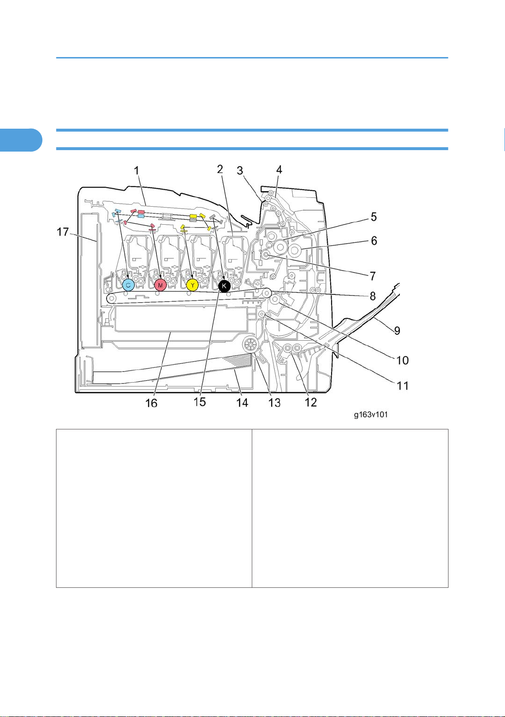
Machine Overview
Component Layout
1. Laser Optics Housing Unit
10. Transfer Roller
2. Print Cartridge (AIO)
11. Registration Roller
3. Paper Exit
12. By-pass Feed Roller
4. Inverter Path
13. Paper Feed Roller
5. Fusing Belt
14. Tray 1
6. Pressure Roller
15. OPC (AIO)
7. Fusing Lamp
16. Waste Toner Bottle
8. ITB (Image Transfer Belt) Unit
17. EGB/ Controller Board
9. By-pass Tray
10
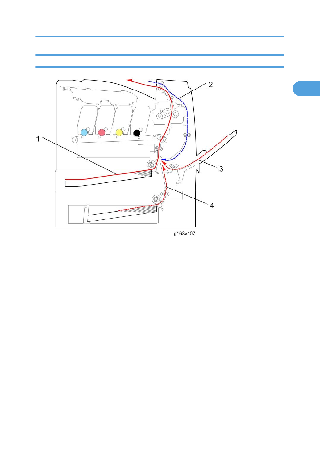
Paper Path
1
Machine Overview
1. Paper path from the tray 1 to the output tray
Paper path in the duplex path
2.
3. Paper path from the by-pass tray
4. Paper path from the optional tray 2 to the output tray
11
1. Product Information
1
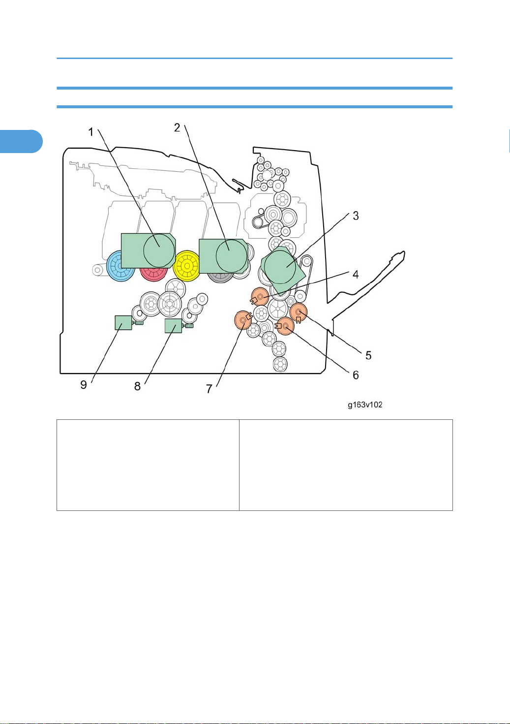
Drive Layout
1. Color AIO Motor
6. By-pass Clutch
2. Black AIO Motor
7. Paper Feed Clutch
3. Transport/Fusing Motor
8. Agitator Motor
4. Registration Clutch
9. ITB (Image Transfer Belt) Contact Motor
5. Duplex Clutch
• Color AIO Motor:
This drives the color AIO cartridges (Cyan, Magenta and Yellow)
• Black AIO Motor:
This drives the black AIO and the ITB (Image Transfer Belt).
• Transport/Fusing Motor:
This drives the fusing unit, paper feed roller, registration roller and paper exit roller* via the paper
feed clutch, registration clutch and gears. (*: This motor only drives the paper exit roller in nonduplex models.)
12

• Registration Clutch:
1
This transfers drive from the transport/ fusing motor to the registration roller.
• Duplex Clutch:
This transfers drive from the transport/ fusing motor to the duplex rollers.
• By-pass Clutch
This transfers drive from the transport/ fusing motor to the duplex rollers.
• Paper Feed Clutch:
This transfers drive from the transport/ fusing motor to the paper feed roller.
• Agitator Motor:
This moves the agitators in the waste toner bottle.
• ITB Contact Motor:
This moves the ITB into contact with and away from the color OPCs.
Machine Overview
13
1. Product Information
1
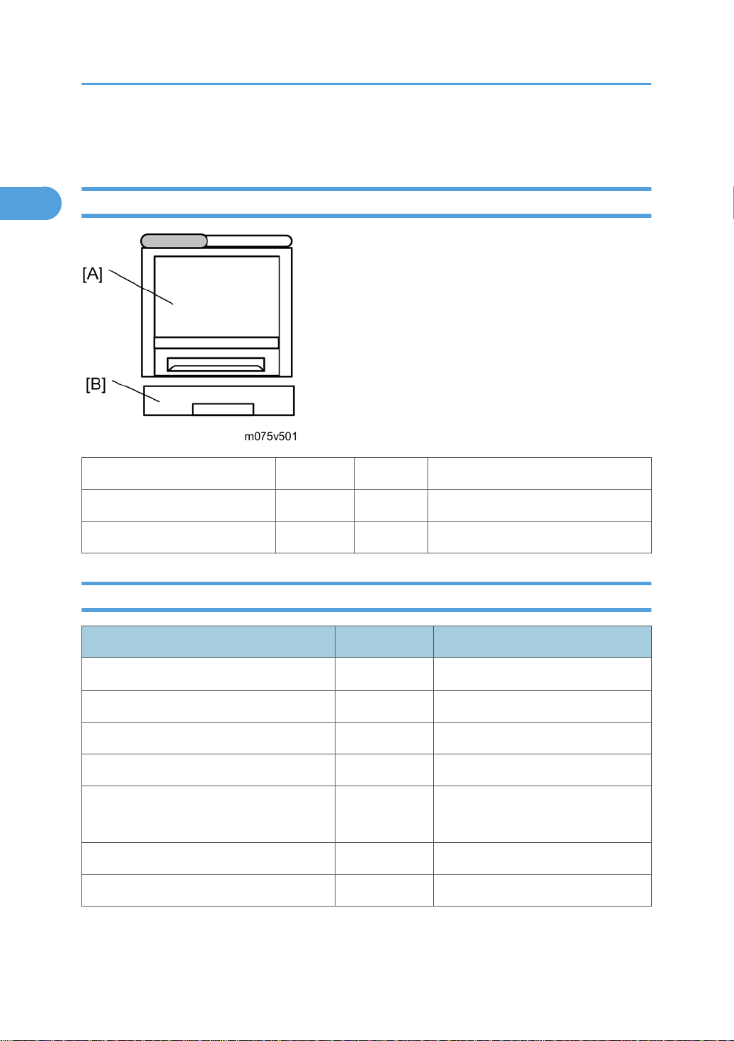
Machine Configuration
Mainframe (M075) and Option
Model Model No. Call out Description
MD –P2 M075 [A] Auto-duplex model
Paper Feed Unit TK 1010 G849 [B] Common with MD-P1
Controller Options
Item Model No. Description
Memory Unit Type G 256MB D362-21 Z-P1/ G-P3/ Al-P1/ KR-P2/ SI-P2
Memory Unit Type I 512MB D435-01 Z-P1/ DI-C1
Camera Direct Print Card Type H M385-01 Z-P1
IEEE 1284 Interface Board Type A B679-17 Z-P1/ KR-P2/ SI-P2
IEEE802.11a/g Interface
Unit Type L/M
Gigabit Ethernet Board Type A G874-01 Z-P1/ KR-P2/ SI-P2
Hard Disk Drive Option Type C320 M394-01 New
M344-01, -02 Z-P1
14

Machine Configuration
1
Item Model No. Description
VM Card (Type O)
NetWare (Type F) M394-10 New
M385-03,
-04, -05
Z-P1 (512 MB memory option is
required.)
15

1. Product Information
1
Guidance for Those Who are Familiar with Predecessor Products
Machine M075 is a similar model with Machine M040/M041. If you have experience with those
products, the following information will be of help when you read this manual.
Different Points from Previous Products
M075 M040/M041
Controller GW controller Non GW controller
SD slot 2 SD slots Not available
Operation panel 4 lines LCD 2 lines LCD
Eco night sensor (New
energy save function)
Available Not available
16
2. Installation
2
RTB 19
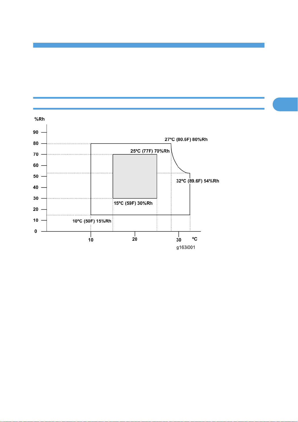
Installation Requirements
Environment
1. Temperature Range: 10°C to 32°C (50°F to 89.6°F)
Humidity Range: 15% to 80% RH
2.
3. Ambient Illumination: Less than 2,000 lux (do not expose to direct sunlight)
4. Ventilation: 3 times/hr/person
5. Do not put the machine in areas that get sudden temperature changes. This includes:
• Areas directly exposed to cool air from an air conditioner
• Areas directly exposed to heat from a heater.
6. Do not put the machine in areas that get exposed to corrosive gas.
7. Do not install the machine at locations over 2,500 m (8,125 ft.) above sea level.
8. Put the machine on a strong, level base. (Inclination on any side must be no more than 5 mm.)
9. Do not put the machine in areas with strong vibrations.
17
2. Installation
2
Machine level
Front to back: Within 5 mm (0.2") of level
Right to left: Within 5 mm (0.2") of level
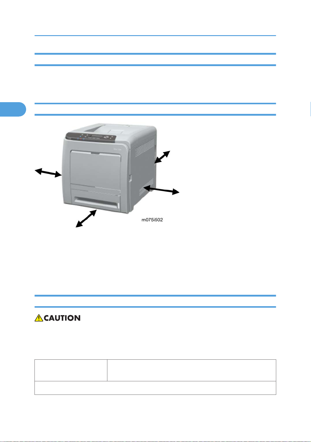
Machine Space Requirement
Put the machine near the power source with these clearances:
Left side: Over 20 cm (7.9")
Rear: Over 10 cm (4")
Right side: Over 10 cm (4")
Front: Over 70 cm (27.5")
Power Requirements
• Make sure that the plug is tightly connected to the outlet.
Avoid multi-wiring.
•
• Make sure that you ground the machine.
Input voltage level
Permitted voltage fluctuation: 10%
120 V, 60 Hz: More than 11 A (for North America)
220 V to 240 V, 50 Hz/60 Hz: More than 6 A (for Europe/ Asia)
18

Do not set anything on the power cord.
2
Installation Procedure
Refer to the Quick Installation Guide for details about installing the machine.
Installation Requirements
19

2. Installation
2
20

3. Preventive Maintenance
3
Preventive Maintenance
See "Appendices" for the "Preventive Maintenance".
21

3. Preventive Maintenance
3
22

4. Replacement and Adjustment
4
Before You Start
• If there are printer jobs in the machine, print out all jobs in the printer buffer.
• Turn off the main power switch and unplug the machine before you do the procedures in this
section.
• Always touch a grounded surface to discharge static electricity from your hands before you handle
SD cards, printed circuit boards, NVRAM or memory boards.
23

4. Replacement and Adjustment
4
Special Tool
SD card
•
24
Exterior Covers
4
Exterior Covers
• Turn off the main power switch and unplug the printer before you do the procedures in this section.
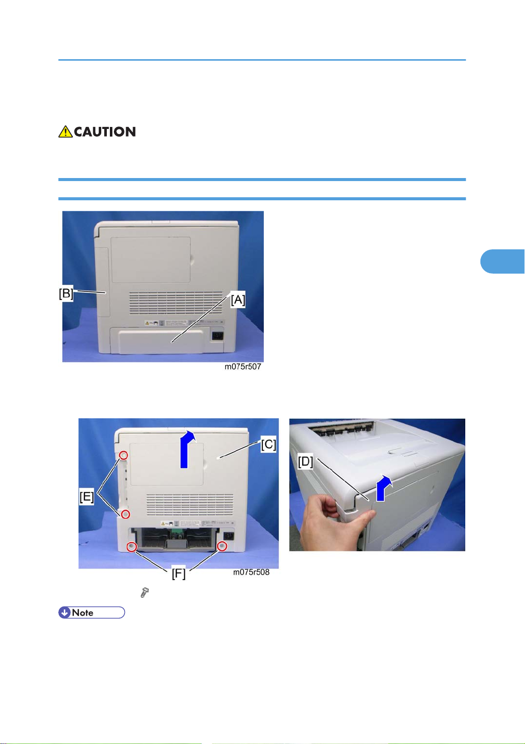
Rear Cover
1. Rear tray cover [A] (hooks)
Interface cover [B] (hooks)
2.
3. Rear cover [C] ( x 4)
• After removing four screws from the rear cover, pull the rear cover from the top right [D] to the top
left while lifting up the rear cover
Upper screw [E]: "M3x8" x 2, Lower screws [F]: "M4x10" x 2
•
25
4. Replacement and Adjustment
4
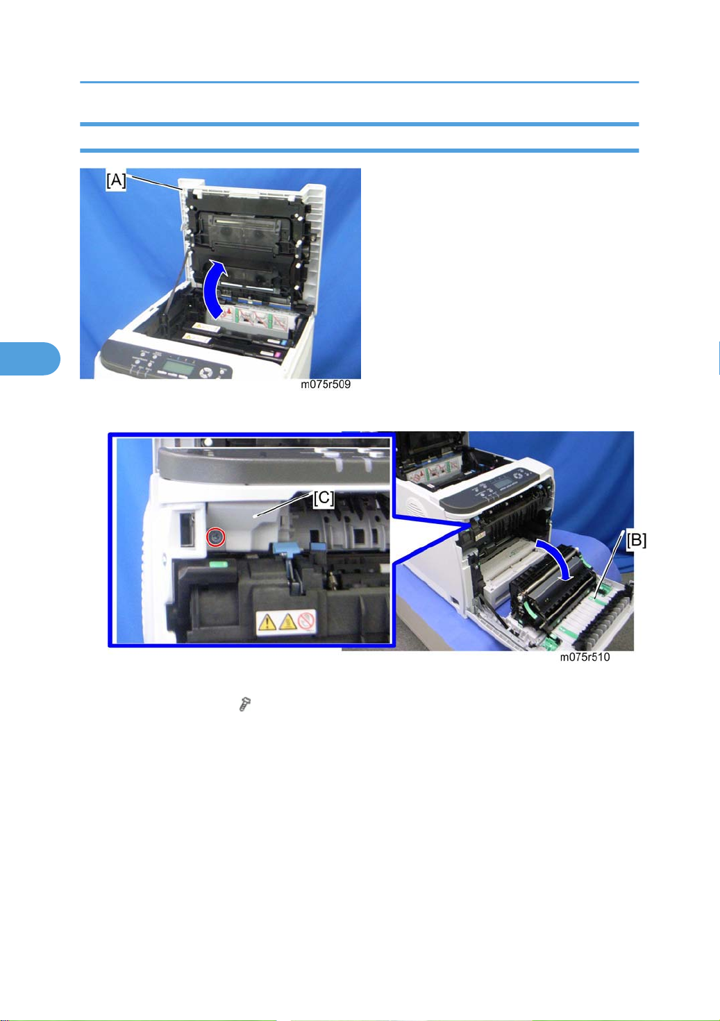
Operation Panel
1. Open the top cover [A].
26
2. Open the front cover [B].
Front harness cover [C] (
3.
x 1)
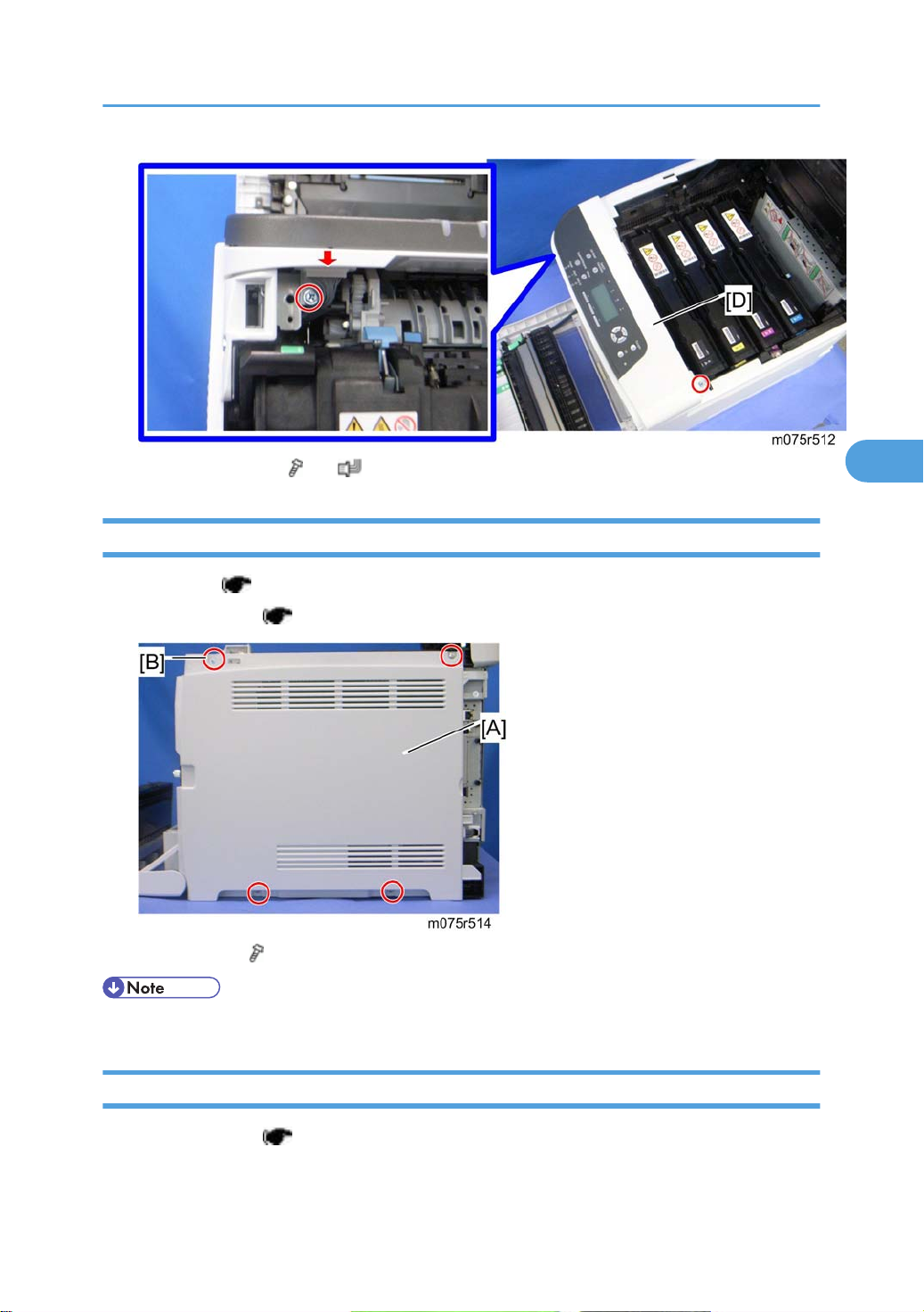
4. Operation panel [D] ( x 2, x 1)
4
Right Cover
1. Rear cover ( p.25)
Exterior Covers
Operation panel (
2.
3. Right cover [A] ( x 4)
• Top front screw [B]: M3x8, others: M4x10
p.26)
Left Cover
1. Operation panel ( p.26)
27
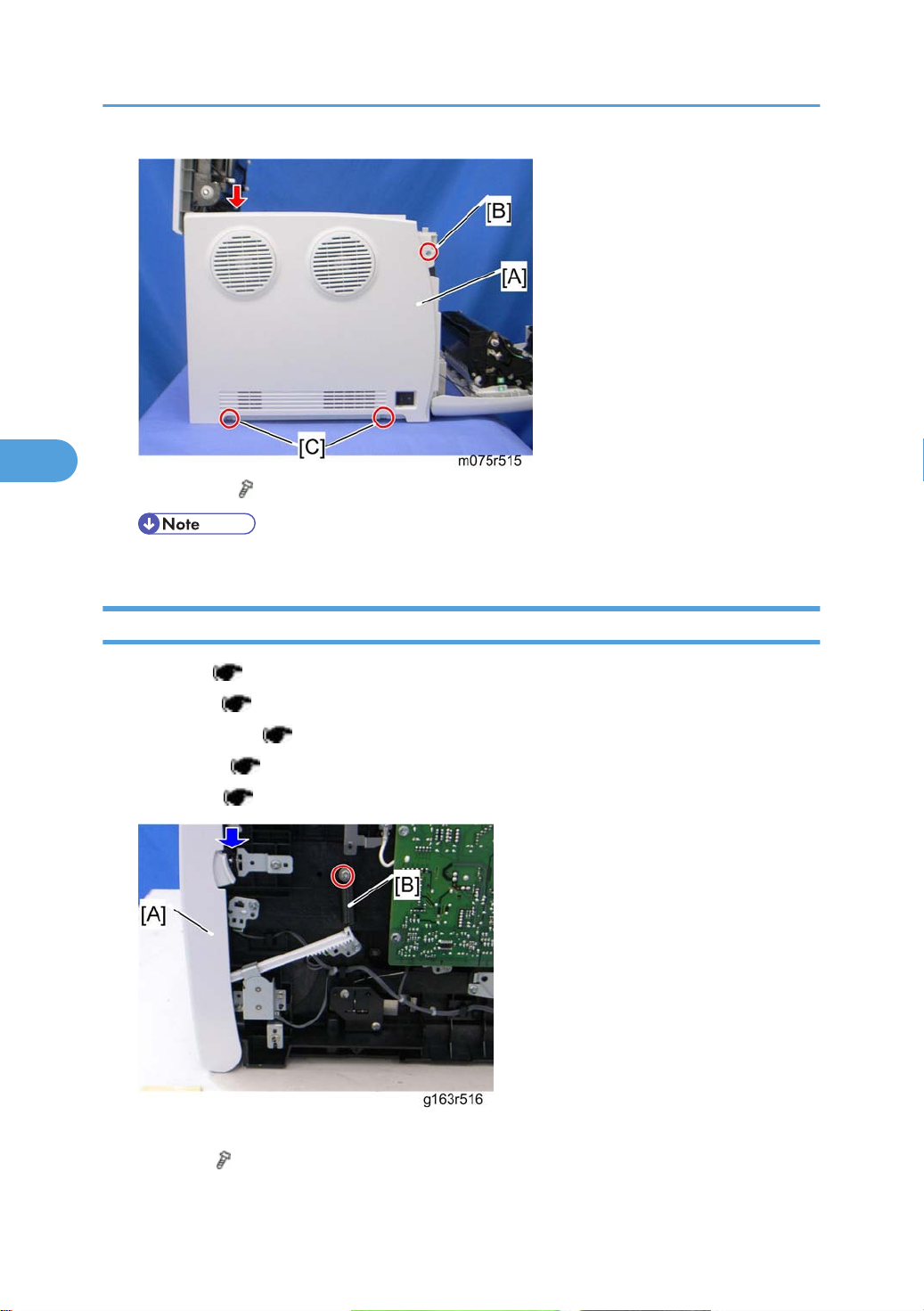
4. Replacement and Adjustment
4
2. Left cover [A] ( x 3, hook at arrow mark)
• Top front screw [B]: M3x8, others [C]: M4x10
Front Cover Unit
1. Left cover ( p.27)
Rear cover (
2.
Operation panel (
3.
Transfer unit (
4.
Right cover (
5.
6. Close the front cover [A].
p.25)
p.50)
p.27)
p.26)
28
Spring [B] (
7.
x 1)
 Loading...