

Page 1

IMPORTANT SAFETY NOTICES
PREVENTION OF PHYSICAL INJURY
1. The wall outlet should be near the copier and easily accessible.
2. Note that some components of the copier and the paper tray unit are
supplied with electrical voltage even if the main switch is turned off.
3. If any adjustment or operation check has to be made with exterior covers
off or open while the main switch is turned on, keep hands away from
electrified or mechanically driven components.
4. If the hot roller temperature is low when the main switch is turned on, the
copier starts process control self check automatically. Keep hands away
from the mechanical and the electrical components to avoid any injury.
5. If the start key is pressed before the copier completes the warm-up period
(Start key starts blinking red and green alternatively), keep hands away
from the mechanical and the electrical components as the copier starts
making copies as soon as the warm-up period is completed.
6. The inside and the metal parts of the fusing unit become extremely hot
while the copier is operating. Be careful to avoid touching those
components with your bare hands.
HEALTH SAFETY CONDITIONS
1. Never operate the copier without the ozone filters installed.
2. Always replace the ozone filters with the specified ones at the specified
intervals.
3. Toner and developer are non-toxic, but if you get either of them in your
eyes by accident, it may cause temporary eye discomfort. Try to remove
with eye drops or flush with water as first aid. If unsuccessful, get medical
attention.
OBSERVANCE OF ELECTRICAL SAFETY STANDARDS
1. The copier and its peripherals must be installed and maintained by a
customer service representative who has completed the training course
on those models.
2. The RAM board on the main control board has a lithium battery which can
explode if replaced incorrectly. Replace the battery only with an identical
one. The manufacturer recommends replacing the entire RAM board. Do
not recharge or burn this battery. Used batteries must be handled in
accordance with local regulations.
1996 By Ricoh Com pany Ltd. All rights r eserved
Page 2
SAFETY AND ECOLOGICAL NOTES FOR DISPOSAL
1. Do not incinerate the toner bottle or the used toner. Toner dust may ignite
suddenly when exposed to open flame.
2. Dispose of used toner, developer, and organic photoconductor according
to local regulations. (These are non-toxic supplies.)
3. Dispose of replaced parts in accordance with local regulations.
4. When keeping used lithium batteries in order to dispose of them later, do
not put more than 100 batteries per sealed box. Storing larger numbers or
not sealing them apart may lead to chemical reactions and heat build-up.
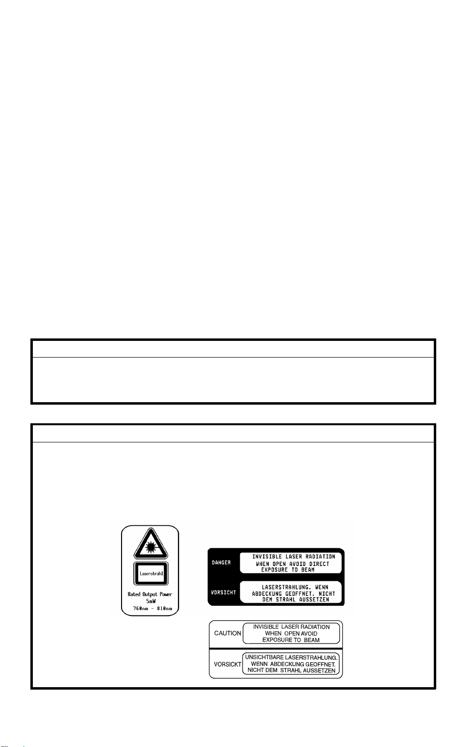
LASER SAFETY
The Center for Devices and Radiological Health (CDRH) prohibits the repair
of laser-based optical units in the field. The optical housing unit can only be
repaired in a factory or at a location with the requisite equipment. The laser
subsystem is replaceable in the field by a qualified Customer Engineer. The
laser chassis is not repairable in the field. Customer engineers are therefore
directed to return all chassis and laser subsystems to the factory or service
depot when replacement of the optical subsystem is required.
DANGER
Use of controls, or adju stm ent, or performance of procedures other
than those specified in this manual may result in hazardous radiation
exposure.
WARNING FOR LASER UNIT
DANGER: Turn off the main switch before attempting any of the
procedures in the Laser Unit section. Laser beams can
seriously damage your eyes.
CAUTION MARKING:
Page 3

INTRODUCTION
The A172/A199 copier (product name: LILY) is based on
the base copier.
(DFC-ALPHA)
This documentation gathers the A172/A199 differing points from the base
copier that service personnel will need to maintain this copier. Therefore, this
documentation should be treated as a insert version of the base copier’s
service manual, although it has a separate binder. It should always be utilized
together with the base copier’s service manual.
,
the A109 copier
Page 4

SECTION 1
OVERALL
MACHINE INFORMATION
Page 5
10 May 1996 MACHINE CONFIGURATION
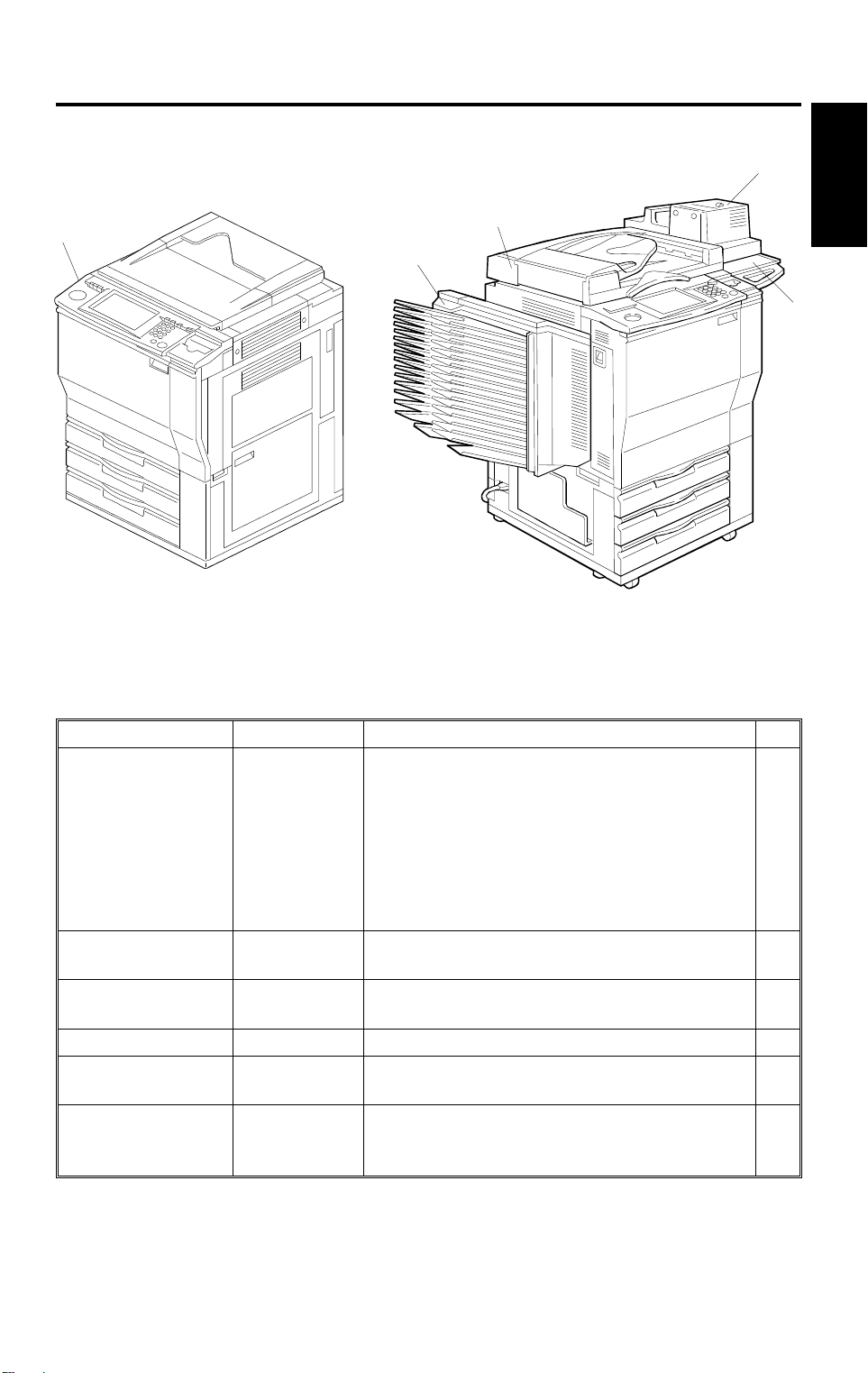
1. MACHINE CONFIGURATION
2
1
4
Overall
Information
3
5
- Copier -
A172V500.wmf
- Full System -
A172V501.wmf
Item Machine Code Note No.
Copier
Dual Job Feeder
Sorter (15-bin)
Film Projector Unit
Holder
Language RO M
board
(for operation panel)
A172
A199
A610
A322
A718
A702-18
A654
A172 is the edit version with a full color
•
operationpanel.
A199 is the non-e di t version with a bla ck &
•
white operati on panel.
An English language ROM board is installed
•
in -17/29/10/22/15 machines.
No language ROM board is installed in
•
-27/26 machines.
Common with A1 75/ A176/A177/A191/A192
•
copiers.
A sorter adapter ( A527) is require d fo r
•
installation.
A holder (A702- 18) i s required for inst all ation.
•
The holder can be installed independently as
•
an original table.
The following languages are available:
•
English (A4), Ger man, French, Ital ian,
Spanish, (Universal).
1
2
3
4
5
—
1-1
Page 6

SPECIFICATIONS 10 May 1996
2. SPECIFICATIONS
2.1 SPECIFICATIONS
Specifications are subject to change without notice.
Configuration: Console
Copy Process: Dry electrostatic transfer system
Resolutions: 400 dpi
Gradations: 256 gradations
Original Type: Sheet/book, object
Original Size: Maximum: A3 (lengthwise), 11" x 17" (lengthwise)
Original Alignment: Rear-left corner
Paper Tray: 64 - 104.7 g/m2 or 17 - 28 lb
Copy Paper Weight:
•
Bypass Feed Tray: 64 - 157 g/m2 or 17 - 42 lb
•
Available Copy Paper Size:
Tray Paper Directi on A4/A3 version LT/DLT version
1st /2nd
Tray
3rd Tray
Bypass
Feed
Tray
Lengthwise
Sideways
Lengthwise
Sideways A4, B5, A5, 11" x 8
Lengthwise
Sideways
Non-standard
paper size
2
NOTE:
With paper heavier than 104.7 g/m
or
28 lb, use the bypass feed tray and
select Thick Paper mode.
A3, A4, 8
1/4
8
A4, A5 11" x 8
A3, B4, A4, B5, A5, 11" x 17" (DLT ), 11" x 15", 10" x 14",
1/2
8
1/2
8
A3, B4, A4, B5, A5, B6, A6 11" x 17" (DLT), 10" x 14",
A4, B5, A5, B6, 8
Horizontal di rection: 148 - 432 mm or 5.8" - 17.0"
Vertical directi on: 100 - 297 mm or 3.9" - 11.7"
1/2
" x 13" (F4),
" x 13"
" x 14" (LG), 8
1/2
" x 13" (F4), 8
" x 11" (LT), 8" x 10
1/2
1/2
" x 11" 8
1/2
", 8" x 10", 5
" (LT), 8
11" x 17" (DLT), 11" x 15",
10" x 14", 8
1/2
" x 14" (LG),
8" x 13" (F),
1/2
8
" x 11" (LT),
1/2
8" x 10
1/2
8
1/2
1/2
8
", 8" x 10"
1/2
" (LT),
1/2
" x 5
" x 5
" (HLT)
1/4
" x 13", 8" x 13" (F ),
1/2
1/2
" x 8
" (HLT)
1/2
" x 11" (LT),
" (HLT)
8" x 13" (F),
1/2
5
5
1/2
x 8
1/2
" x 11" (LT),
1/2
" x 8
1/2
" (HLT)
" (HLT)
1-2
Page 7

10 May 1996 SPECIFICATIONS
Warm-up Time:
First Copy Time:
1/2
(A4 or 8
" x 11" sideways)
Copying Speed:
(Standard modes)
About 8 minutes (at 20°C or 68°F)
Full Color (4 scans): 15.5 seconds
•
Single Color:
•
Black, Yellow, Magenta, Cyan: 8.8 seconds
Red, Green, Blue, Orange, Light Green:
11.5 seconds.
NOTE:
1) When selecting OHP/Thick Paper
modes, copying speed is reduced.
2) After changing some modes, the first
copy time will take longer than usual.
Full Color (4 scans):
•
1/2
A4 or 8
" x 11" sideways: 6 copies/minute
A3 or 11" x 17": 3 copies/minute
Single Color (Black, Yellow, Magenta, Cyan):
•
A4 or 8
1/2
" x 11" sideways: 31 copies/minute
A3 or 11" x 17": 15 copies/minute
Single Color
•
(Red, Green, Blue, Orange, Light Green):
A4 or 8
1/2
" x 11" sideways: 10 copies/minute
A3 or 11" x 17": 5 copies/minute
Overall
Information
NOTE:
When selecting OHP/Thick Paper
modes, copying speed is reduced.
Non-reproduction Area:
Leading edge: 5 ± 2 mm or 0.2" ± 0.08"
•
Side: 2 ± 2 mm or 0.08" ± 0.08", Total less than
•
4 mm or 0.16"
Trailing edge: 2 ± 2 mm or 0.08" ± 0.08"
•
Copy Number Input: Number keys, 1 to 99
Automatic Reset: 1-minute standard setting; can also be set to 10
to 900 seconds in 1-second steps, or to no auto
reset.
Paper Feed: Paper Tray x 3
(500 sheets of paper each)
Bypass Feed Tray
(50 sheets of paper with paper lighter than
2
104.7 g/m
or 28 lb)
1-3
Page 8

SPECIFICATIONS 10 May 1996
Copy Tray Capacity: 100 sheets of paper
Toner Replenishment: Bottle type (340g/bottle)
A4/A3 version: 25%, 50%, 65%, 71%, 75%,
Reproduction Ratio:
•
82%, 93%, 100%, (Full Size),
115%, 122%, 141%, 200%,
400% + User ratio x 2
LT/DLT version: 25%, 50%, 65%, 74%, 77%,
•
85%, 93%, 100%, (Full Size),
121%, 129%, 155%, 200%,
400%, + User ratio x 2
Zoom: From 25% to 400% in 1% steps
Power Source: 115 V 60 Hz, more than 12 A (for NA)
220 ~ 240 V 50/60 Hz, more than 7 A (for EU
and AA)
Power Consumption:
(Copier only)
Maximum: less than 1.5 kW
•
Warm-up: 1.40 kW
•
Stand-by: 0.93 k W
•
Copy Cycle: 1.20 kW
•
Noise Emission Sound pressure level (The measurements are
made in accordance with ISO 7779 at the
operator position.)
Copier only
Stand-by Less than 42 dB (A)
Copying Less than 56 dB (A)
Sound power level (The measurements are
made in accordance with ISO 7779.)
Copier only
Stand-by Less than 59 dB (A)
Copying Less than 69 dB (A)
Dimensions (W x D x H):
Copier Only:
•
692 x 713 x 1026 mm or 27.3" x 28.1" x 40.4"
Full System*:
•
1499 x 713 x 1099 mm or 59.1" x 28.1" x 43.2"
= Copier + Dual Job Feeder + Sorter + Ho l der
(*
)
1-4
Page 9

10 May 1996 SPECIFICATIONS
Weight:
Optional Equipment
Copier Only: 200 kg or 440.8 lb
•
Dual Job Feeder
•
Sorter
•
Sorter Adapter
•
Projector Unit
•
Holder for Projector Unit
•
Key Counter
•
Interface Kit for Controller
•
Overall
Information
1-5
Page 10

SPECIFICATIONS 10 May 1996
2.2 FUNCTIONS: BASIC MODEL VS EDIT MODEL
This machine comes in two versions. Refer to the following table for features
available on your machine.
Functions Edit type Basic type
Copy Image Density Adjustm ent (Auto/Manual )
Auto Color Selection
Full Color
Back
Single Color
Twin Color
Original Image Type Select io n
Paper Selection (Auto/Manual)
Preset R/E
Reducing/
Enlarging
Shift/Book
Color
Creation
Image
Creation
Color
Adjustment/
Memory
Area Editing
Interrupt Copying
Recall
Auto Reduce/Enlarge
Bypass Feed Copy i ng
Duplex Copying
Default Setting
User Tools
Display Color Full color Black & white
Zoom
Size Magnification
Directional Size Magnification
Poster Mode
Centering/Co rnering
Margin Adjustment
Erase
Single Copies
Color Conversi on
Color Erase
Color Backgroun d
Outline
Positive/Negat i ve
Shadow
Mirror
Slanted
Image Repeat
Image Overla y
User Color Memory
Single Color Adjustment
Color Balance Adjustment
Color Balance Sample
Image Adjustm ent
✓✓
✓✓
✓✓
✓✓
✓✓
✓✓
✓✓
✓✓
✓✓
✓✓
✓✓
✓✓
✓✓
✓✓
✓✓
✓✓
✓✓
✓✓
✓✓
✓✓
✓✓
✓✓
✓✓
✓✓
✓✓
✓✓
✓✓
✓✓
✓✓
✓✓
✓✓
✓✓
✓
✓✓
✓✓
✓✓
✓✓
✓✓
✓✓
✓✓
—
1-6
Page 11

10 May 1996 SPECIFICATIONS
2.3 NEWLY-ADDED OPERATING FEATURES
: Available
No. Features LILY (A172/A199) DFC-ALPHA (A109 )
1 Auto Image Density Full Color & Black Copy Black Copy only
2 Auto Color Calibration
3 Duplex Copying
4 Twin Color
5 Single Color 80 (+1) colors 8 colors
6 User Color 48 colors 3 colors
7 Color Back ground 84 (+1) colors 13 colors
8 Paint 84 (+1) colors 13 colors
9 Color Line
10 Frame Line
11 Image Overlay
12 Area Editing See the next page
(Edit type only)
(Edit type only)
(Edit type only)
: Not Available
✗
✗
✗
✗
✗
✗
✗
1. Auto Image Density mode can be selected when in Full Color mode.
2. Auto Color Calibration can be performed by the user.
3. Using the by-pass feed tray, rear side copying is available.
Overall
Information
4. Twin Color mode copies black parts in black and other parts in the
selected colo r .
5. Single Color
(8 colors x 4 density levels) + (12 user colors x 4 density levels) + 1 scan
color = 81 colors
* scan color = Edit type only
6. User Color
12 colors x 4 density levels = 48 possible colors
The total percentages of the mixed colors must be 255% or less.
7. Color Background
(9 colors x 4 density levels) + (12 user colors x 4 density levels) + 1 scan
color = 85 colors
* scan color = Edit type only
8. Paint (Edit type only)
(9 colors x 4 density levels) + (12 user colors x 4 density levels) + 1 scan
color = 85 colors
* Scan color = Edit type only
9. Color Line (Edit type only)
In the Area Editing mode, designated lines can be colored.
Available colors: 85 colors = 81 Single colors + (Bk x 4 density levels)
1-7
Page 12

SPECIFICATIONS 10 May 1996
10. Frame Line
In the Area Editing mode, the outlines of the designated areas can be
colored.
11. Image Overlay
This function makes a copy merging images of two originals.
12. Area Editing mode
LILY (A172) DFC-ALPHA (A109)
Area Shape Rectangle, Polyg on, R ight Angle
Polygon, Close d Loop, Line
Number of Areas Maximum: 500 points
However, 1 area or li ne must be of
30 or fewer points.
Method of
Designati ng
Areas
Canceling Ar eas Not only single point s but al r eady
Maximum
Number of
Groups/Areas
Storin g the Area
Editing job
settings in
Program Mode
Canceling
Groups
Editor Pen and Cursor Cursor only
closed areas can b e cl eared.
15 Groups
Up to 3 job patterns can be applied .
Changing the color of one job
pattern will not affect the original
settings of the job pattern.
Always available. Not available in Creative Editing
Available. However, canceli ng a
group will remove it from the total
number of grou ps.
Rectangle, Polygon, Right Angle
Polygon, Closed Loop
Creative Editi ng: 6 Are as
1 area must be of 10 orfewer points
Color Editing: 6 Groups
Maximum 500 points
Only single points before closing
the area can be cleared.
Creative Editi ng: 3 Are as
Color Editing: 6 Groups
When in Color Editing mode, up to
3 job patterns can be applied,
Changing the color of one job
pattern will not affect the original
settings of the j ob pattern.
mode.
Available in Color Editing mode.
Not available.
1-8
Page 13

10 May 1996 SPECIFICATIONS
MEMO
Overall
Information
1-9
Page 14
MECHANICAL COMPONENT LAYOUT 10 May 1996
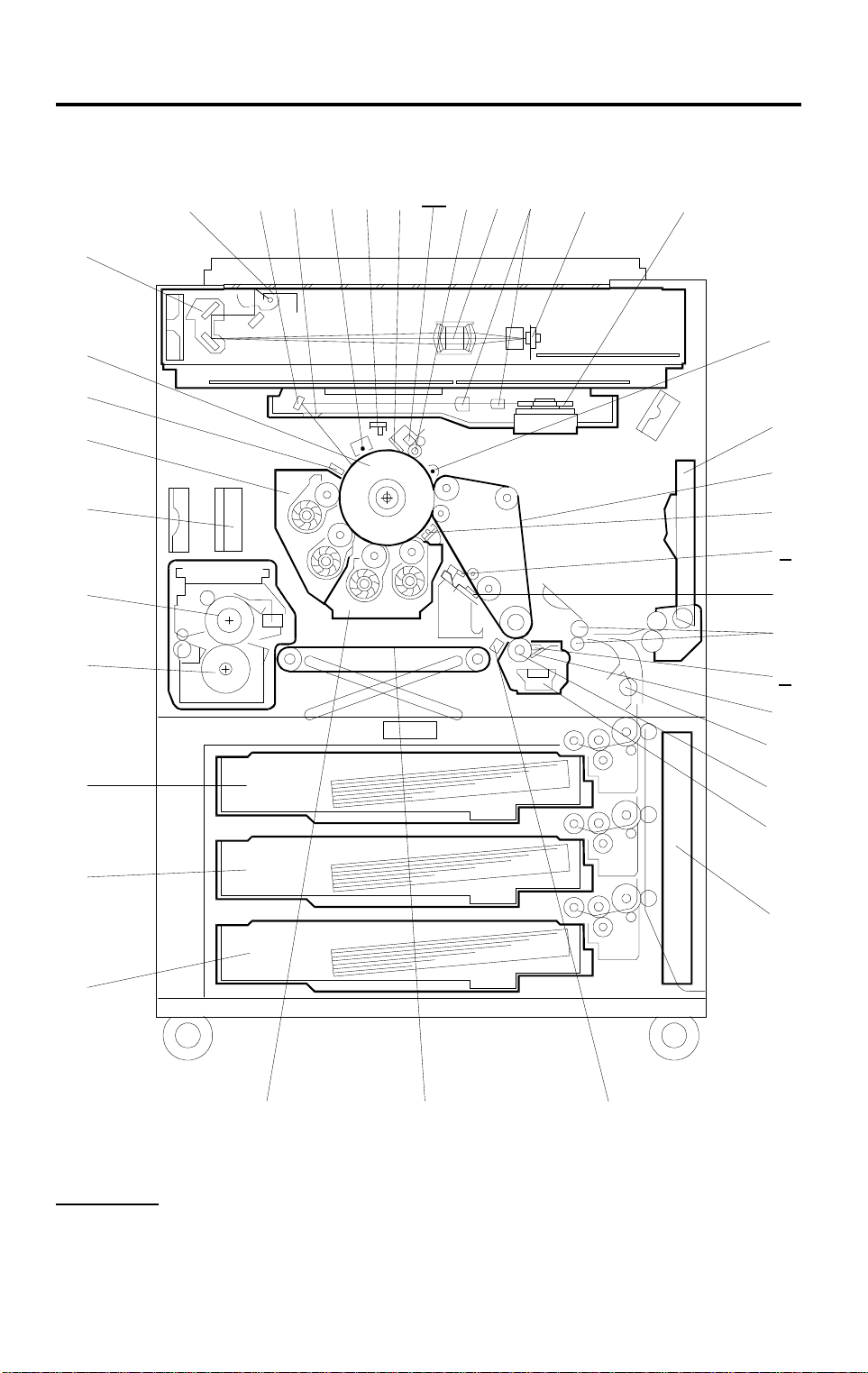
3. MECHANICAL COMPONENT LAYOUT
37
38
1
2
3
26
25
24
23
27
28
29
30
31
32
33
3534
36
22
21
20
19
18
17
4
5
6
7
8
9
10
11
12
13
16
Units different from A109
Bold Italic
Bold
: Additional units
: Modified units
15
1-10
14
A172V502.wmf
Page 15

10 May 1996 MECHANICAL COMPONENT LAYOUT
1. Pre-cleaning Corona Unit
20. Pressure Roller
Overall
Information
2. By-pass Feed Table
3. Transfer Belt
4. ID Sensor
5. Belt Lubricant Bar
6. Belt Cleaning Blade
7. Registration Rollers
8. Roller Lubricant Bar
9. Transfer Roller Blade
10. Relay Roller
11. Transfer Roller
12. Toner Catch Pan
13. Toner Collection Bottle
14. Paper Discharge Plate
21. Hot Roller
22. Development Ozone Filter
23. Black/Cyan Development Unit
24. Drum Potential Sensor
25. OPC Drum
26. 2nd Scanner
27. 1st Scanner
28. Drum Mirror
29. Toner Shield Glass
30. Charge Corona Unit
31. Quenching Lamp
32. Drum Cleaning Blade
33. Drum Lubricant Bar
15. Transport Belt
16. Magenta/Yellow Development
Unit
17. 3rd Paper Tray
18. 2nd Paper Tray
19. 1st Paper Tray
Deleted units from A109
Lubricant brush
•
34. Cleaning Brush
35. Lens
36. f-theta Lenses
37. CCD Board
38. Polygon Mirror
1-11
Page 16
DRIVE LAYOUT 10 May 1996
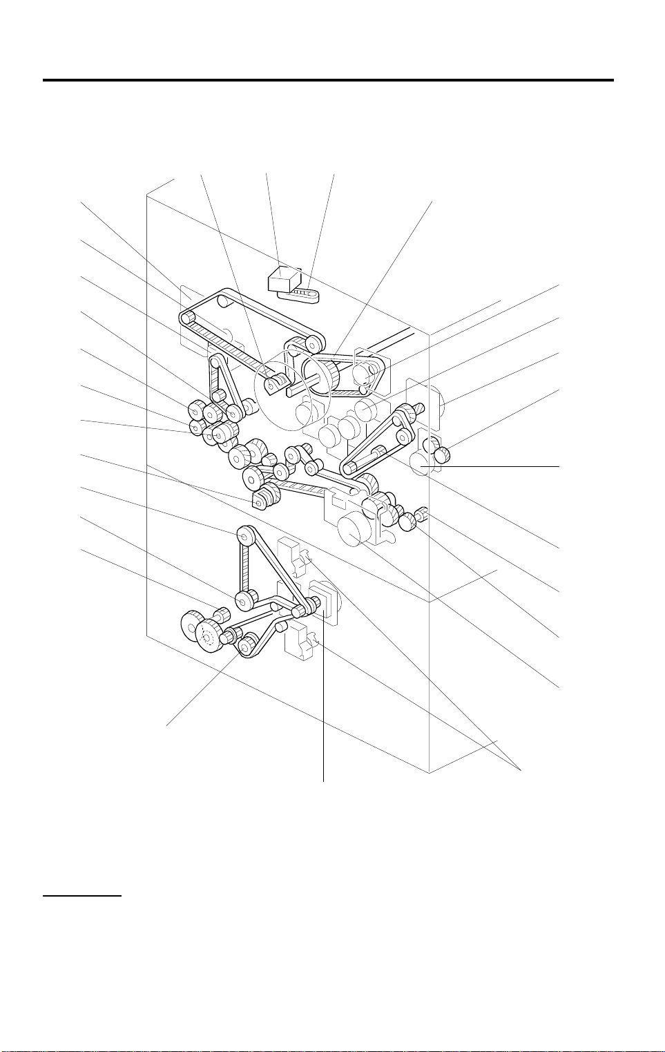
4. DRIVE LAYOUT
27
26
25
24
23
22
21
20
19
18
17
1
2 3
4
5
6
7
8
9
10
16
Units different from A109
Bold Italic
Bold
: Additional units
: Modified units
11
12
13
14
15
A172V503.wmf
1-12
Page 17

10 May 1996 DRIVE LAYOUT
1. Transfer Belt Position Clutch
15. Paper Feed Motor
Overall
Information
2. Scanner Motor
3. Scanner Drive Pulley
4. Drum Timing Belt
5. Drum Motor
6. Bk-Sleeve Motor
7. Color-Development Drive Motor
8. Bk-Development Drive Gear
9. Bk-Development Drive Motor
10. Color-Development Drive Gear
11. Transport Unit Drive Gear
12. Fusing Unit Drive Gear
13. Transport Motor
14. Tray Lift Motors
16. 3rd Paper Feed Drive Pulley
17. Toner Collection Tank Drive Gear
18. 2nd Paper Feed Drive Pulley
19. 1st Paper Feed Drive Pulley
20. Transfer Roller Position Clutch
21. Registration Clutch
22. Relay Roller Drive Gear
23. By-pass Feed Drive Gear
24. Transfer Belt Drive Pully
25. Transfer Belt Motor
26. Lubricant Brush Clutch
27. Cleaning Motor
1-13
Page 18

ELECTRICAL COMPONENT DESCRIPTIONS 10 May 1996
5. ELECTRICAL COMPONENT DESCRIPTIONS
Refer to the electrical component layout on the waterproof paper in the
pocket for symbols and index numbers.
Symbol Name Function Index No.
Printed Circuit Boards
PCB1 DC power supply Provides dc power. 20
PCB2 Lamp regulato r Provides d c power for the exposure l am p. 1
PCB3
PCB4
PCB5
PCB6
PCB7
AC drive Provides ac power for the hot roller and
pressure rol ler fusing lam ps.
High voltage supply C/G
High voltage supply -BSupplies high vol t age to the Y/M/C/Bk sleeve
High voltage supply T1/PCC/BR
High voltage supply -T2Supplies high voltage to the tra nsf er roller.
Supplies high voltage to the ch ar ge corona
and grid plate.
rollers as development bias or to the OPC
drum for drum potential sensor calibration.
Supplies high voltage to the be l t bias roller,
pre-clean i ng corona, and cleaning bias roll er.
11
12
26
13
17
PCB8
PCB9
PCB10
PCB11
PCB12
PCB13
PCB14 Noise filter Removes electrical noise. 23
PCB15 ID sensor Detects the density of the ID sensor pattern. 127
PCB16
PCB17 Polygon motor drive Controls the polygon motor speed. 8
PCB18
PCB19
PCB20
PCB21 Image Discriminate Used for anticou nt erfeiting. 6
PCB22
High voltage supply -DSupplies high voltage to the pa per di scharge
plate.
Main control Controls all copier functions both directly or
through othe r co ntrol boards.
Interface 1 Interfaces th e i nput/output of ele ct rical
components with the main control board.
Interface 2 Interfaces th e i nput/output of ele ct rical
components with the main control board.
Transfer belt motor
drive
Paper feed inter face Interfaces the inpu t/ output of electrical
Operation panel Cont rols the touch panel display and
CCD Converts the li ght reflected fr om th e original
Scanner contro l Processes R/G/B video signals fr om th e
Scanner drive Interfaces the input/output electrical
Display Editor
interface
Controls the speed and directi on of the
transfer bel t mot or.
components in the paper supply unit with the
main control board.
monitors the key matrix.
into analog electrical signals for the three
basic colors (R/G/B).
CCD board to be sent to the IPU board.
components in the optics cavity with the
scanner contr ol board.
Interfaces th e operation panel board with the
IPU board (A17 2 copier only).
22
15
21
18
14
19
25
9
7
3
10
1-14
Page 19

10 May 1996 ELECTRICAL COMPONENT DESCRIPTIONS
Symbol Name Function Index No.
PCB23
PCB24
PCB25
PCB26
PCB27
PCB28 Paper width detecting Detects paper width in the by-pass feed table. 128
PCB29 Wire cleaner drive Controls ths corona wire cleaner operation. 16
Motors
M1
M2 C - Sleeve Turns the C sleeve roller in both di r ections. 31
M3 M - Sleeve Turns the M sleeve rol l er in both directions. 35
M4 Y - Sleeve Turns the Y sleeve roller in both direc tions. 34
M5 Drum Turns the drum. 28
M6 Bk - Sleeve Turns the Bk - sleeve roller in both directions. 30
M7
M8
M9
M10 Scanner Drives the 1st and 2nd scanners. 29
M11
M12
M13 Polygon Turns the polygon mirror . 47
M14
M15
M16
M17
M18 1st tray lift Lifts the 1st tray bottom plat e. 36
M19 2nd tray lift Lifts the 2nd tray bottom p l at e. 37
M20 3rd tray lift Lifts the 3rd tray bottom pl at e. 38
Operation Pane l
Control
IPU Processes R/G/B video si gnals from the
IPU interface Changes the clock frequency of R/G/B video
LD drive Generates the laser beam for printing the
Laser synchronizing
detector
Bk - Development
drive
Transport Drives the transport uni t , fusing unit, transf er
Color - Development
drive
Cleaning Drives th e dr um cleaning bru sh, the lubricant
Transfer belt Turns the transfer belt drive rol l er i n both
Paper feed Drives the pap er feed sections and the cam
Bk - Toner supply Dri ves the Bk toner tran sport and agitati on
C - Toner supply Dri ves the C toner transport and agita tion
M - Toner supply Drives the M toner transport a nd agitation
Y - Toner supply Drives the Y toner transpor t and agitation
Controls the operation pan el .
scanner control board and sends Y/M/C / Bk
video signals to the LD unit.
signals and al so sends the synchr oni zing
signal for the polygon motor.
latent image on the drum.
Detects the laser beam to control the start
timing of main scan writing.
Drives the Bk dual mixing roller.
roller, and transfer belt cleani ng unit.
Drives the Y/M/C dual mixing rollers
simultaneously.
brush, and the tr ansfer belt relea se
mechanism.
directions .
gear for the tone r collection bot tle.
mechanism.
mechanism.
mechanism.
mechanism.
24
2
4
5
66
46
45
27
32
33
39
43
42
41
40
Overall
Information
1-15
Page 20

ELECTRICAL COMPONENT DESCRIPTIONS 10 May 1996
Symbol Name Function Index No.
M21 Wire cleaner Drives the wire/grid cleaner 44
Fan Motors
FM1 Fusing exhaust Removes heat from around the fusing unit. 49
FM2
FM3
Charge inlet Provides air flow around th e drum charge
section.
Inner cooling Provides ai r f low around the toner ta nk and
development uni t s.
48
57
FM4 IPU cooling Provides air flow around the IPU board. 52
FM5 Polygon motor cooling Provides air flow around the polygon motor. 53
FM6/7
FM8/9
FM10
Transport Sucks in air to attract co py paper to the
transport belts.
Development exhaust Removes air and heat from aroun d th e drum
and development units.
Optics exhaust Exhausts air from under the le ns housing
cover.
55/54
58/59
51
FM11 LD cooling Provides air fl ow to the LD unit. 50
FM12/13 Optics cooling Blows air into the optics cavity. 60/61
FM14
DC power supply
cooling
Provides air flow to transformers and
radiation plates on the dc power supply
56
board.
Sensors
S1
S2
By-pass feed tab l e Detects whether the by-pass feed table is
open or cl osed.
Oil end Detects whether the silicone oil tank is nearly
empty or not.
S3 Exit Detects misfeeds. 100
S4
S5
Transfer belt posi t i on Detects whether the transfer belt is i n contact
with the drum or not .
Humidity Detects humidity and temperature to
calculate th e absolute humidi t y.
S6 Drum potential Detects the drum surface potential . 125
S7
S8
S9
S10
M - Toner densit y Detects the toner density in the M
development uni t .
Y - Toner density Detects the toner density in the Y
development uni t .
Bk - Toner density Detects the toner density in th e Bk
development uni t .
C - Toner density Detects the toner density in the C
development uni t .
S11 Transport Detects misfeeds. 95
Registration Detects the leading edge or trailing edge of
S12
the copy pape r to control the rotat ion of the
paper feed and r egi stration rollers.
S13
Registratio n guide set De te ct s w het her the registrati on guide plate
is set or not.
73
91
67
88
97
96
101
98
74
70
1-16
Page 21

10 May 1996 ELECTRICAL COMPONENT DESCRIPTIONS
Symbol Name Function Index No.
S14 Bk - Toner End Detects the toner end condition of Bk toner. 94
S15 C - Toner End Detects th e to ner end conditio n of C toner. 93
S16 M - Toner End D etects the toner end condition of M t oner. 92
S17 Y - Toner End Detects the toner end condi tion of Y toner. 90
S18
S19
S20
S21
S22
S23
S24
S25
S26
S27
S28
S29
S30
S31 Ori gi nal length - 1 D etects original length. 65
S32 Ori gi nal length - 2 D etects original length. 63
S33 Original width Detects original width. 106
S34
S35
S36
Transfer roller position Detects whether the t ra nsfer roller is in
contact with the transfer belt or not.
By-pass paper end Detects whether there is paper on the
by-pass feed table or not.
By-pass lengt h Detect s w het her paper on the by-pass feed
table is long er than A4 (Letter) side w ays or
not.
Toner overflow Dete ct s w het her the toner coll ect i on bottle is
full or not.
1st lift Detects the height of the paper st ack in the
1st paper tray to stop the 1st tray lift motor.
2nd lift Detects the height of the paper st ack in the
2nd paper tray to stop the 2nd tray li ft m ot or.
3rd lift Dete ct s the height of the pa per st ack in the
3rd paper tray to stop the 3rd tray lift motor.
1st paper end Detects whethe r there is paper in the 1st
paper tray or n ot .
2nd paper end Detects whether there is paper i n th e 2nd
paper tray or n ot .
3rd paper end Detects whether there is paper i n th e 3rd
paper tray or n ot .
1st paper feed Controls the 1st paper feed cl ut ch off/on
timing and the 1st pick-up sol enoid off timing.
2nd paper feed Cont ro l s the 2nd paper feed cl ut ch of f /on
timing and the 2nd pick-up solenoid off
timing.
3rd paper feed Controls the 3rd paper feed clutch off / on
timing and the 3rd pick-up sol enoid off timing.
Scanner unit lif t Detect s whether the scanner unit is lifted or
not.
Platen cover po si t i on Informs the CP U w het her the platen cov er is
up or down (related to APS/ARE function).
Scanner HP Informs the CPU whether the 1s t an d 2nd
scanners are at th e hom e position or not.
72
71
69
86
76
77
80
89
87
84
82
85
83
64
62
107
Overall
Information
Switches
SW1/2/3/4
Front door safet y Cuts the ac power line throu gh R A 1 and
detects whether the front door i s open or not.
1-17
102/103/
104/105
Page 22

ELECTRICAL COMPONENT DESCRIPTIONS 10 May 1996
Symbol Name Function Index No.
Vertical transport set Cuts the ac power line through RA1 and
SW5/6
detects whether the vertical transport guide
78/79
is open or not.
Main Provides power to the copier.
When it is at the st andby position, the
SW7
electrical power is suppli ed only to the
99
heaters (drum, optics anti-condensation,
tray, transfer belt/roller).
SW8
SW9
SW10
2nd paper size Detects the paper size for the 2nd paper tray
and whether the tr ay i s set or not.
3rd tray set Detects whether the 3r d paper tray is set o r
not.
1st paper size Detects the paper size for the 1st paper tray
and whether the tr ay i s set or not.
75
81
68
Magnetic Clutches
Transfer belt position Controls the touch and release operation of
MC2
the transfer be l t by u si ng drive from the
108
cleaning mot or.
MC3
By-pass feed Starts pap er feed from the by-p ass feed
table.
111
MC4 Registration Drives the registration r ol l ers. 110
Transfer roller position Controls the touch and release oper at i on of
MC5
the transfer ro ll er unit by using dri ve from the
109
transport motor.
MC6 1st feed Starts pap er feed from the 1st paper tr ay. 1 13
MC7 2nd feed Starts paper fee d from the 2nd paper tray. 114
MC8 3rd feed Starts paper feed from t he 3r d paper tray. 115
Solenoids
SOL1
SOL2
SOL3
SOL4
SOL5
SOL6
SOL7
SOL8
Cleani ng entran ce
seal
Controls the touch and relea se operation of
the cleaning entrance seal on t he t ransfer
belt cleaning unit.
Lubricant ba r Control s the touch and release operation of
the lubricant bar.
Cleaning blade Controls the touch and release operation of
the belt cleaning blade.
By-pass pick-u p Controls th e up/ down movement of the
pick-up roller in the by-pass feed station.
1st pick-up Controls the up/down movement of the
pick-up roller in the 1st feed station.
2nd pick-up Controls the up/down movement of the
pick-up roller in the 2nd feed st at i on.
3rd pick-up Controls the up/down movement of the
pick-up roller in the 3rd feed sta tion.
1st separation roller Controls th e up/ down movement of the
separation roller in the 1st feed station.
1-18
122
124
123
112
121
119
117
120
Page 23

10 May 1996 ELECTRICAL COMPONENT DESCRIPTIONS
Symbol Name Function Index No.
SOL9
SOL10
Lamps
L1 Fusing Provides heat to the hot roller. 144
L2 Pressure Provides heat to the pressure roller. 143
L3
L4
Heaters
H1
H2
H3/H4
H5
H6
2nd separati on r ol l er Controls the up/down movement of the
separation roller in the 2nd feed station.
3rd separation roller Contro l s the up/down move ment of the
separation roller in the 3rd feed station.
Exposure Applies high intensity light to the original for
exposure.
Quenching Neutralizes any char ge remaining on the
drum surfa ce af t er cl eaning.
Lower tray (opti on) Turns on when t he m ai n switch is off to keep
paper dry in the 3r d paper tray.
Upper tray (opti on) Turns on when t he m ai n switch is off to keep
paper dry in the 1st and 2nd paper trays.
Transfer belt /rol l er Turns on when t he t ransfer roller
thermoswi t ch detects 20C° or less to keep
the resistance of the transfer ro ll er at a
constant level.
Optics
anti-condensation
Drum Turns on when t he main switch is off to
Turns on when t he main switch is off to
prevent moisture from forming on the optics.
prevent moisture from forming around the
drum.
118
116
129
126
138
134
136/137
148
131
Overall
Information
Thermistors
TH1 Fusing Monitors the temperature of th e hot roller. 133
TH2
Thermofuses
TF1
TF2
Thermoswit ches
TS1
TS2
Pressure roll er Monitors the tem per at ure of the pressur e
roller.
Fusing Opens the fus i ng l amp circuit if th e fusing
unit overheats.
Pressure roller Opens the pressure roller lamp circuit if the
fusing unit ov er heats.
Optics Opens the exposure lamp circuit if the 1st
scanner overheats.
Transfer belt /rol l er Detects the te m per ature around the transfer
roller in order to keep the resist ance of the
transfer roller at a constant level.
1-19
142
132
141
130
135
Page 24

ELECTRICAL COMPONENT DESCRIPTIONS 10 May 1996
Symbol Name Function Index No.
Counters
Black total Keeps track of the total number of scans for
CO1
Full color total Keeps track of the total numb er of scans for
CO2
Others
CB1
NF1 Noise filter Removes electrical noise. 140
CC1 Choke coil Removes high frequency cur r ent . 147
Circuit break er Provides back-up hi gh current protection for
black devel opment in both bl ack and color
copy modes.
Yellow, Magenta, and Cyan development in
both single and full color copy modes.
the electrical components.
145
146
139
1-20
Page 25

SECTION 2
DETAILED DESCRIPTIONS
Page 26

10 May 1996 MAJOR DIFFERENCES FROM THE DFC-ALPHA (A109)
1. MAJOR DIFFERENCES FROM THE
DFC-ALPHA (A109)
No. Item Contents Details
Process Control
Toner End
1
Detection
Latent Image
2
Control
Toner Density
3
Control
Around The Drum
OPC Drum The OPC drum layer material
1
Drum Charge
2
Wire
Drum Charge
3
Wire/Grid
Cleaning
Drum Cleaning Drum lubrication has been newly
4
The toner end detection software
has been eliminated.
The process control for latent
image control has been modified.
CNT
V
Correction has been
modified.
(Charge Transf er L ayer: CTL)
has changed.
The system has been changed
from a double-wi r e t o a
single-wire scorotron.
Drum charge wire/grid cleaning
has been newly added.
added.
The cleaning brush has been
changed from a looped-bristle
type to a straight- br i st l e ty pe.
A toner end sensor has been
added for each color. See 6.2 in
section 2 for deta i l s.
See 2.1 in section 2 for d et ai l s.
See 2.2 in section 2 for d et ai l s.
To reduce ozone a nd N O
reaction with the drum (to
prolong the life time of the drum).
See 3.1 in section 2 for d et ai l s.
See 3.2 in section 2 for d et ai l s.
See 3.4 in section 2 for d et ai l s.
To apply the lubricant evenly on
the drum. See 3.4 in section 2 for
details.
X
Detailed
Descriptions
Optics
Exposure Lamp The number of exposure la mp’s
1
Infra-red Filter The thickness of the inf ra-red
2
2nd/3rd Mirrors A heavier stabilizer has been
3
Exposure Glass A more high- conductivity gl ass is
4
Reflectors Reflectivity has increased
5
lighting points has increased
from 7 to 9.
filter has increased from 0.8 mm
to 1.0 mm.
installed on the 2nd/3rd mirrors.
used.
because of surface
improvements.
To decrease whit e bands on
copies caused by t he exposure
lamp’s lighting points.
To achieve better copy quality for
originals containing infra-red
radiance.
(prevents black areas from
becomi ng reddish)
To decrease scanner banding to
achieve better results for auto
letter/photo separation.
To decrease the possibility of the
exposure glass becoming dirty
with dust particl es.
To decrease the te m perature
around the optics c avi t y due to
less power to the exposure lamp.
2-1
Page 27

MAJOR DIFFERENCES FROM THE DFC-ALPHA (A109) 10 May 1996
No. Item Contents Details
Optics Cooling
Fan Filter
6
The filter material has changed. It
is easier to repla ce the filter.
The air flow has improved to
reduce temperature rises in the
optics cavity. For replacement,
see sec t i on 5 for det ails.
Image Processing
RGB Filter The RGB filter coefficient for
1
each copy mode (l et t er /photo)
To improve gradation and
reproduction quality.
has been changed.
Color Correction New matrixes and masking
2
coefficients have been added to
See 4.4 in section 2 for d et ai l s.
match the new copy modes.
Image
3
Separation IC
The image separ at i on IC has
been changed.
To reduce photo/ le t te r image
separation err or s i n auto detect
mode.
Laser Exposure
Drum Mirror A heavier stabilizer has been
1
installed on the Drum mirrors.
To reduce the occur r ence of
banding on copies.
Development
Development
Sleeve Roller
1
The sleeve roll ers have been
changed to a sand-blast type.
Toner Tank
Toner Tank A toner end sensor has been
added for each col or.
The gree n lever has been
eliminated.
1
A toner tank detection
mechanism has been added.
When the tank is pul l ed out, it is
disconnected e lectrically from th e
main body.
Transfer B el t
Transfer Belt
Bias
1
The number of threshold levels
that de cide transfer bel t bi as
depending on environmental
conditions has changed from 2 to
4.
Transfer Belt
Cleaning
2
The belt lubricant mechanism
has changed to ap pl y l ubricant
directly to the transfer belt.
To eliminate th e 1. 25 mm
horizontal lines in halftone image
areas caused by the grooves on
the sleeve roller.
See 6.2 in section 2 for d et ai l s.
See 6.2 in section 2 for d et ai l s.
See 6.2 in section 2 for d et ai l s.
See 7.1 in section 2 for d et ai l s.
To prevent partial bl anking of
lines (due to incomplete toner
transfer) from appearing on
copies.
See 7.2 in section 2 for d et ai l s.
2-2
Page 28

10 May 1996 MAJOR DIFFERENCES FROM THE DFC-ALPHA (A109)
No. Item Contents Details
Transfer R ol ler
Transfer
Belt/Roller
1
Heater
Transfer Rolle r The material of the transfer ro l le r
2
Transfer Roller
Bias
3
Paper
Discharge Plate
4
Paper
5
Discharge Plate
Output
Transfer Roller
6
Cleaning
The transfer roller heater has
been newly added to keep the
temperature around the transfer
roller unit at 20°C.
has been changed.
The number of threshold levels
that decide transfer roller bias
depending on environmental
conditions has been changed
from 2 to 4.
Transfer roller bi as settings for
duplex copyin g have been newly
added.
The installed a ngle of the paper
discharge plate has changed.
The output of the paper
discharge plate changes
depending on the copy paper.
The roller lubricant mechanism
has been newly added.
See 8.1 in section 2 for d et ai l s.
To improve tran sf er e ffi ciency.
See 8.2 in section 2 for d et ai l s.
See 8.2 in section 2 for d et ai l s.
To prevent toner scatter from
appearing around solid areas in
duplex mode. See 8. 4 i n section
2 for details.
See 8.4 in section 2 for d et ai l s.
See 8.3 in section 2 for d et ai l s.
Detailed
Descriptions
Fusing Unit
Hot Roller The material of the hot roller has
1
Pressure Roller The material of the pressure
2
Pressure Roller
3
Cleaning
Paper Feed
2nd Paper
1
Feed Station
Operation Panel
LCD (Liquid
Crystal Display)
1
been changed.
roller has been changed.
The pres sure rol l er cleani ng
mechanism has been newly
added.
The 2nd paper feed st at i on has
been changed to the universal
tray type.
The LCD has been changed to a
640 x 480 dot type.
A172: Full Color Display
A199: B/W Display
To make it suitable for duplex
copying.
To make it suitable for duplex
copying.
See 9.1 in section 2 for d et ai l s.
To meet customer s’ requests.
For easier operation and editing.
2-3
Page 29

MAJOR DIFFERENCES FROM THE DFC-ALPHA (A109) 10 May 1996
No. Item Contents Details
Operation
Panel Control
2
Operation
Panel Self
3
Diagnostic
Mode
Others
Drum Dri ve Th e drum drive me chanism has
1
Copier Rear
2
Frame
Fusing exhaust
3
ozone filter
The operation panel control
board has been ne w l y added.
The main control board no longer
contr ols the operation panel.
The operation panel self
diagnostics mode has been
newly added.
been changed from a series of
gears to a timing belt system.
The thickness of the rear frame
has changed from 1. 6 mm to 2.0
mm
This filter has been eliminated. Because the ozone amount has
For easier servi cing of the
machine.
Banding on copie s are reduced.
See 3.3 in section 2 for d et ai l s.
Banding on copie s are reduced.
been decrease d due to the new
charge corona unit.
—
Options
1 DJF (A610) See the DJF section for details. —
15-Bin Sorter
2
(A322)
Holder
3
(A702-18)
Film Projector
4
Unit (A718)
See the Sorter section for details.
The colo r of t he exterior covers
has been changed.
See the Film Projecto r Uni t
section for details.
—
—
—
2-4
Page 30
10 May 1996 PROCESS CONTROL
2. PROCESS CONTROL
2.1 LATENT IMAGE CONTROL
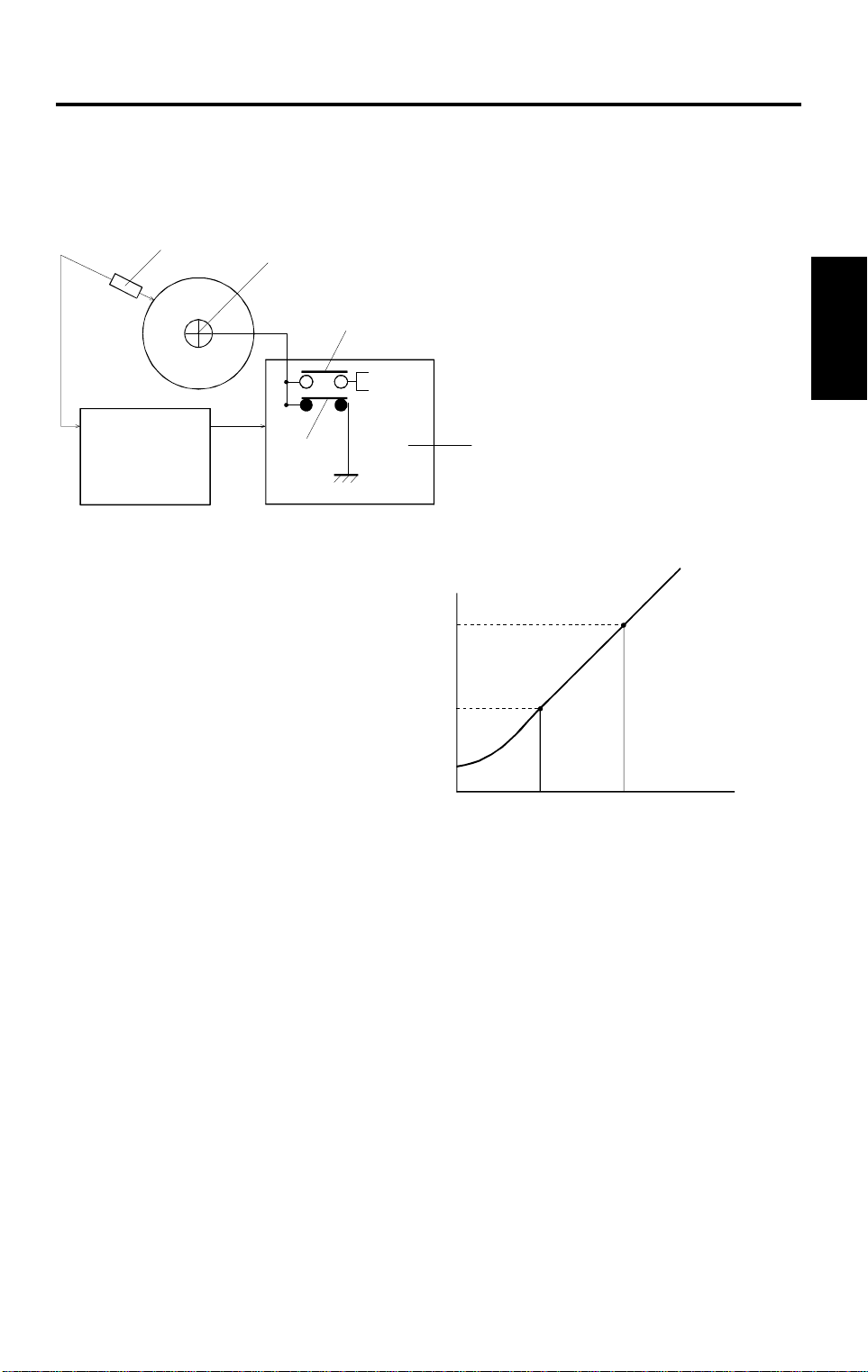
2.1.1 DRUM POTENTIAL SENSOR CALIBRATION
[A]
Main Board
[C]
RA #1
RA #2
RA#1 and RA #2 are packed in RL1 on
the High Voltage Supp l y Boar d – B.
–300 V
–600 V
A172D507.wmf
Sensor Output
V600 (V
V300 (V
)
2
1
)
Detailed
Descriptions
[B]
–300 –600
Actual Voltage
A172D508.wmf
The drum potential sensor [A] output is calibrated during the process control
self check.
The High Voltage Supply Board - B [B] has two relay contacts. Usually RA #1
grounds the drum. However, during the self check, the main CPU turns RA
#2 on and RA #1 off and applies the test voltage to the drum shaft [C]. In this
condition, the drum is isolated from the ground (floating).
By measuring the output of the drum potential sensor when –300 V (V
–600 V (V
) are applied to the drum, the sensor output is calibrated
600
300
) or
automatically. (The machine can now determine the actual drum potential
from the potential sensor output.) Using -300 and -600 V results in a more
accurate calibration of the sensor, since the voltage applied to the supply
board is much closer to the actual value, which is –450 V for V
B
(Development bias) during the process control self check.
2-5
Page 31

PROCESS CONTROL 10 May 1996
2.1.2 GRADATION PATTERN DETECTION
LD Power Level
40 mm
1st
40 mm
2nd
3rd
13th
A172D510.img
14th
A172D509.wmf
A latent image of a 14-grade gradation pattern is created for each color (Bk,
C, M, Y) by changing the LD input current.
By creating 14 grades, the machine can achieve a more precise development
gamma factor, resulting in a more reliable pointer control.
2-6
Page 32

10 May 1996 PROCESS CONTROL
2.2 TONER DENSITY CONTROL
2.2.1 V
T
V
2.5
CNT
CORRECTION
Copies
A172D511.wmf
Average ≥ 3.8
Average ≤ 2.3
2
Pattern Density (mg/cm
Gain Value = –1
Gain Value = ±0
)
Drum Potential
[A]
[C]
[B]
Detailed
Descriptions
A172D512.wmf
Gain value = +1
A172D513.wmf
Even if the toner concentration is constant, the toner density sensor output
gradually increases after new developer is installed because of developer
characteristics. Because of this, the machine believes that the amount of
toner in the developer has reduced. This causes the machine to increase the
toner concentration because the machine controls the toner concentration so
that V
To compensate for this, the V
T
stays constant.
CNT
gain is corrected by using the development
gamma curve made from the 14-grade pattern during process control self
check.
The present gamma curve [A] and the previous gamma curve [B] are
compared, and the average [C] is calculated. As shown in the diagram, the
gain is decreased by 1 when the average gradient is 3.8 or more. The
maximum compensation value is –16.
Because of this new V
CNT
correction system, the V
CNT
correction previously
performed every 200 copies is no longer necessary. Also, due to the use of
the average value, over-reduction of the gain is avoided.
2-7
Page 33

PROCESS CONTROL 10 May 1996
2.2.2 FORCED TONER CONSUMPTION MECHANISM
For customers that mainly make copies other than full color copies, the
toners other than the selected colors are not used. For these toners, the
amount of toner inside the development unit will gradually increase every 50
copies, since toner agitation is performed at this interval, and some toner is
added at this time (see section 6.1). If this condition continues, toner
scattering and toner density control failure may occur.
To compensate for this, along with the transport screw gear modification, the
machine checks the output of each TD sensor during the process control self
check. If the machine detects V
REF-VT
≥ 0.3 V, it determines that there is too
much toner inside the development unit and makes a pattern across the
whole width of the drum to forcibly consume some toner.
2.2.3 FORCED TONER SUPPLY MECHANISM
When the machine makes consecutive copies that have a large portion of
solid image areas, toner supply and agitation from the toner tank cannot keep
up with the toner consumption speed, causing lighter copies, toner scatter,
and related SC codes to appear.
To compensate for this, the output of each TD sensor is checked every copy.
When the machine detects V
T-VREF
≥ 0.5 V five times consecutively, it
determines that the amount of toner in the development unit is low. At this
moment, the copy job is interrupted, and toner is fed into the development
unit forcibly. After forced supply, the machine resumes the copy job.
2-8
Page 34

10 May 1996 DRUM UNIT
3. DRUM UNIT
3.1 DRUM CHARGE
This copier uses a single corona wire scorotron system to charge the drum.
The corona wire applies a negative charge to the drum surface. The striped
stainless steel grid plate makes the corona charge uniform and controls the
negative charge on the drum surface to -650 V (standard) by applying a
negative grid bias voltage.
The high voltage supply board –C/G gives a constant corona current (–450
A) to the corona wire, and controls the grid voltage (based on the results of
µ
process control) to maintain proper image density. Grid voltage is controlled
to match changing factors such as a dirty grid plate, dirty charge corona
casing, and OPC chargeability.
The use of the single wire scorotron system has the following advantages.
The amount of corrosive gas (O3, NOX) is reduced due to the decrease in
•
total current.
Detailed
Descriptions
The life time of the drum is increased due to the decrease in the amount
•
of corosive gas.
Uneven charge problems are alleviated due to the increase of the amount
•
of current per meter of the corona wire.
2-9
Page 35

DRUM UNIT 10 May 1996
3.2 DRUM CHARGE CORONA WIRE/GRID CLEANING
[E]
[B]
[A]
[F]
[D]
[C]
A172D524.wmf
[G]
A172D525.wmf
The flow of air around the charge corona unit may deposit toner particles and
paper dust on the corona wire or corona grid plate. These particles may
interfere with charging and cause uneven charge on the drum.
The wire cleaner [A], which consists of the wire cleaner pads [B] and the grid
plate sponge [C], automatically cleans the wire and the inside of the grid plate
to prevent such problems from appearing.
The wire cleaner is driven by a dc motor. Normally the cleaner is located at
the front end (this is home position). Whenever the main switch is turned on
while the hot roller temperature is below 80°C (before process control), the
wire cleaner motor [D] turns on to bring the wire cleaner to the rear end of the
corona unit and back to the home position. The corona wire and the inside of
the grid plate are cleaned at the same time. This procedure can be manually
performed with an SP mode as well (<2> SP Test, page 4).
When the cleaner moves from the home position to the rear position (the
white arrow in the illustration), only the grid plate is cleaned since the grid
plate sponge is always in contact. When coming back, the rib [E] on the
cleaner is forced by the opening in the corona casing, and the wire cleaner
pads contact the corona wire.
There are no home position or return position sensors. The wire cleaner drive
board at the back of the machine monitors the current applied to the motor.
When the wire cleaner reaches the end, it is stopped and the motor is locked.
At this time, the current of the motor slightly increases and the drive board
detects that it is time to rotate the motor in reverse.
Also, a grounding plate [F] is installed on the back side of the drum stay [G]
to reduce the electrical noise generated from the cleaner motor.
2-10
Page 36

10 May 1996 DRUM UNIT
3.3 DRIVE MECHANISM
[A]
[B]
A172D500.wmf
The drum is driven by the drum motor [A] through a timing belt [B].
By the use of a timing belt system, banding on copies are reduced due to the
lower mechanical load.
Detailed
Descriptions
2-11
Page 37

DRUM UNIT 10 May 1996
3.4 DRUM LUBRICATION MECHANISM
[A]
[B]
[B]
A172D501.wmf
[A]
A172D502.wmf
While the drum rotates, the cleaning brush [A] distributes lubricant from the
drum lubricant bar [B] to the surface of the drum.
This mechanism improves the copy quality, especially for letter areas in full
color mode, since it helps the toner transfer to the transfer belt. It also
improves the efficiency of drum cleaning.
To apply the lubricant to the surface of the drum evenly, a straight-bristle type
is used for the drum cleaning brush.
2-12
Page 38

10 May 1996 IMAGE PROCESSING
4. IMAGE PROCESSING
4.1 IPU SECTION BLOCK DIAGRAM
LD
Unit
Video
Controller
Bk, C, M, Y
Filter
Printer
Gradation
•
•
• Image
Creation
Detailed
Descriptions
I/F
Color ControllerDisplay Editor I/F Board
Magnification•
•
RGB
γ
Scanner
Picture
•
• Color
Correction
I/F
Filter
Element
Correction
ACS
Area
CPU
Auto L/P
Image Separation
Memory
Main Control Board
Board
IPU I/F
Board
Control
Scanner
IDU
A172D535.wmf
2-13
Page 39

IMAGE PROCESSING 10 May 1996
4.2 ACS (AUTO COLOR SELECTION)
Signal
Level
RBG
*MIN: Also known as "RGB Common D ata"
In Auto Color Selection mode, the Black Copy mode or Full Color mode is
automatically selected to match the original image. During the 1st scanning
cycle, the latent image is developed with amount of black toner according to
the corrected R/G/B video signals. If the original does not have any color
area, the 2nd scanning is aborted, and the developed image is transferred
from the transfer belt to copy paper. Then the black and white copy comes
out. If the original has a color area, copying resumes in the full color copy
mode (4 scans).
MAX
MIN
A172D526.wmf
To recognize if the original has a color area or not, the R/G/B video signals
are compared. If the maximum difference among R/G/B signal levels
(MAX-MIN in the above diagram.) is within a certain range, the original is
considered to be black and white.
This range can be changed by the user.
Black: The range is wider
Color: The range is narrower
Also, the user can select either B/W Priority or Color Priority, to reproduce the
B/W areas or Color areas well, when the ACS mode is selected.
*Factory Setting = Color Priority
2-14
Page 40

10 May 1996 IMAGE PROCESSING
When Color Priority is selected
Bk Conversion Data
255 : Letter areas
UCR
setting 1
0 255
<ACS: Color Priority>
UCR ratio: 100%
4
3
2
5
: Photo areas
8
7
6
9
RGB Common Data
Detailed
Descriptions
A172D527.wmf
a) Letter areas
The UCR ratio is set to 100% to reproduce the letter areas well. Black toner
is always used if RGB Common Data is greater than zero.
b) Photo areas
In photo areas, black toner is not used until RGB Common Data reaches a
certain value, which depends on the UCR adjustment setting (see below).
This can be one of 9 settings as shown in the above illustration.
Also, the UCR ratio changes with image density. The steeper the gradient in
the above graph, the faster the UCR ratio increases with image density (as
RGB Common Data increases).
The UCR range for the photo areas can be changed over 9 levels by the user
(Image Adjustment: UCR Adjustment) to get the best color reproduction.
2-15
Page 41

IMAGE PROCESSING 10 May 1996
When B/W Priority is selected
Bk Conversion Data
255 : Letter areas
0 255
<ACS: B/W Priority>
: Photo areas
UCR ratio: 100%
RGB Common Data
A172D528.wmf
a) Letter areas
The UCR (Under Color Removal) ratio is set to 100% to reproduce the letter
areas well.
b) Photo area
The UCR ratio is set to a higher value than for the Color Priority default
setting (level 5), so that low image density areas of B/W originals can be
reproduced well.
2-16
Page 42

10 May 1996 IMAGE PROCESSING
4.3 RGB FILTER
RGB Filter
RGB Input
Filtering
ADS (Full Color)
RGB Output
(to Color Correction)
A172D529.wmf
4.3.1 Filtering
To improve the image reproduction, the appropriate filter coefficients are
applied to the R/B/G video signals, depending on the selected image modes
(letter/photo) or the result of Auto Letter/Photo separation.
4.3.2 Auto Image Density Control (Full Color)
This mode prevents the background of an original from appearing on copies.
The Auto Image Density Level can be changed using the User Tools. (There
are 5 levels.)
Detailed
Descriptions
When Full Color mode and Auto Image Density mode are selected, video
signals corresponding to the background are detected and their output level
is set to zero. The threshold for detecting the background can be changed
over 5 levels using the User Tools.
RGB
Output Data
RGB Input Data
Threshold
A172D533.wmf
2-17
Page 43

IMAGE PROCESSING 10 May 1996
4.4 COLOR CORRECTION
(from RGB Filter)
RGB Input
Color
Correction
Positive/Negative
Background Density Control
YMCBk
CPU
Memory
Contrast
ADS
(B/W, Twin Color, Single Color)
ACC
Scan
Color
YMCBk
Color Conversion
YMCBk Output
A172D541.wmf
2-18
Page 44

10 May 1996 IMAGE PROCESSING
4.4.1 Image Modes
RGB video signals are converted to YMCBk video signals using a color
conversion table.
A172D530.wmf
a) Printed Photo/Glossy Photo mode
A suitable color conversion table for Printed Photo or Glossy Photo mode is
applied to improve the reproduction of such originals.
b) Copied Photo/Map mode
A suitable color conversion table for Copied Photo or Map mode is applied to
improve the reproduction of such originals.
c) Auto Letter/Photo mode
At the factory setting, Printed Photo mode is applied for the photo areas
detected by the Auto Letter/Photo mode.
The user can change this setting so that either of the following modes will be
applied for photo areas.
Printed Photo mode
•
Glossy Photo mode
•
Copied Photo mode
•
Detailed
Descriptions
2-19
Page 45

IMAGE PROCESSING 10 May 1996
4.4.2 Backgr ound Density Control
RGB
Output Data
Darker
Setting
Lighter
Setting
RGB Input Data
A172D531.wmf
There a 9 levels of background density controls.
a) Lighter setting
Small effect on the high image density areas, but the low image density areas
are reproduced lighter or erased.
b) Darker setting
Small effect on the high image density areas, but the low image density areas
are reproduced darker.
When combining the Full Color mode and Auto Image Density mode, the
background density may be reproduced lighter or erased. To reproduce the
color background well, it is necessary not to use Auto Image Density mode
but to adjust the background density control to a darker setting.
2-20
Page 46

10 May 1996 IMAGE PROCESSING
4.4.3 Con trast
RGB
Output Data
Weaker
Stronger
RGB Input Data
A172D532.wmf
Contrast between light and dark areas of the image can be adjusted. There
are over 9 levels.
a) Strong setting
The density of the dark image areas is increased and the density of the light
image areas is decreased.
b) Weaker setting
The density of the dark image areas is decreased and the density of the light
image areas is increased.
Detailed
Descriptions
2-21
Page 47

IMAGE PROCESSING 10 May 1996
4.4.4 Auto Image Density Control (B/W, Twin Color, Single Color)
This mode prevents the background of an original from appearing on copies.
The Auto Image Density Level can be changed using the User Tools. (There
are 5 levels.)
When B/W, Single Color, or Twin Color and Auto Image Density mode are
selected, this function combines the Background Density Control and
Contrast as shown in the following table.
ADS Level
↑
Dark +1
Standard 0
Light –1
↓
+2
–2
Backgro und
Density Control
–1 0
–1 +1
–1 +2
–2 +2
–2 +3
Contrast
2-22
Page 48

10 May 1996 IMAGE PROCESSING
4.5 ACC (AUTO COLOR CALIBRATION)
Test Pattern
Bk
Target
Actual
C
M
Bk
C
M
γ
γ
Photo mode
Y
Letter mode
Y
(4 scan)
A172D534.wmf
Detailed
Descriptions
Image Density
LM H
A172D540.wmf
Auto Color Calibration can be performed using the User Tools.
A test pattern, including the patterns for Letter mode and Photo mode, will be
printed first. The user then scans the test pattern. The resulting printer
gamma curve depends on the results of scanning the test pattern.
There are adjustment tables for L, M, H, and ID MAX values stored in the
machine. The machine applies these to approximate the actual curve to the
target curve as closely as possible.
If needed, the printer gamma curve can be adjusted further manually in the
SP mode. (See section 5, Color Balance Adjustment)
Also, a printer gamma setting can be stored in memory (temporarily or
permanently) and curve can be recalled. When the ACC is performed, the
current printer gamma setting will be automatically stored in the temporary
memory, which can be recalled after the ACC is performed. (See Section 4,
Service Tables, SP Table
.)
2-23
Page 49

IMAGE PROCESSING 10 May 1996
4.6 YMCBk FILTER
In addition to the RGB filter, the most suitable software filter is applied to
YMCBk video signals to improve the image reproduction.
High Contrast filter (emphasizing edges)
•
Smoothing filter
•
Soft
(Smoothing)
Setting 1234567
Applied
Filter Table
Letter
mode
Photo
mode
1234567
0123456
Standard
(Emphasizing Edges)
Sharp
The filter can be selected by the user by adjusting the Sharp/Soft level
(Image Adjustment).
2-24
Page 50

10 May 1996 DEVELOPMENT
5. DEVELOPMENT
5.1 DEVELOPMENT SL EEVE CLEANING
Detailed
Descriptions
A172D506.wmf
To achieve a faster CPM for black and white originals when copying 1 to 1 or
using Auto Color Select (ACS) mode, the development sleeve cleaning mode
previously performed for every original is now performed periodically.
For A4 or smaller size originals, a maximum of 40 black and white copies can
be made without the machine stopping to perform development sleeve
cleaning (20 copies for originals larger than A4 size). If a color original is
detected in between when using ACS mode, the cleaning mode is executed,
and the original counter will be reset. This setting can be changed with SP
mode.
2-25
Page 51

TONER TANK 10 May 1996
6. TONER TANK
6.1 TONER AGITATION
[B]
[A]
A172D503.wmf
Clockwise
Stop
Counter
Clockwise
Clockwise
Stop
Counter
Clockwise
One Cycle
1.0S 0.3 0.30.5S
A172D504.wmf
Cycle12345
Toner End Detection is done here
A172D505.wmf
Under the following conditions, the toner agitator [A] inside each toner tank
rotates to agitate the toner inside the toner tank.
Whenever the main switch is turned on while the hot roller temperature is
•
below 110°C.
After a multi-copy job is completed and more than 50 copies have been
•
made since the last toner agitation.
When the optional ARDF is used, the machine stops the copy cycle after
•
150 copies have been made since the last toner agitation.
When the toner tank is pushed in during a near toner end or toner end
•
condition.
As shown above, one cycle of this agitation consists of rotating in both
directions, and is performed for five consecutive cycles.
In order to prevent unnecessary toner from entering the development unit
during agitation, the transport screw gear [B] has some play before rotation is
transmitted to the transport screw.
2-26
Page 52

10 May 1996 TONER TANK
6.2 TONER END DETECTION
[A]
A172D503.wmf
Four toner end sensors [A] (which are piezoelectric) are installed on the toner
tank to monitor the near end condition for each color toner. Toner end
detection is performed during toner agitation, and the detection sequence is
as follows.
Detailed
Descriptions
1. Near Toner End Condition
The machine starts sampling the output of the toner end sensor every 0.1
second during the last three cycles of the toner agitation process (see the
previous page). If a no toner condition is detected for 90% of the
samples, the machine enters the near toner end condition.
2. Toner End Condition
When a near toner end condition is detected, a total of 30 copies can be
made using the toner for which the near end condition was detected.
After this, the machine enters the toner end condition and copying using
that toner is disabled.
3. Toner End Recovery
When the front door is opened and the toner tank rails are pulled out and
in, the machine starts to perform the toner end recovery procedure. The
sequence and the recovery condition is the same as for the near toner
end condition detection.
If the toner end condition is not cleared, copying using that particular color
toner is disabled. This prevents the customer from clearing the near end or
toner end condition by simply opening and closing the front cover or turning
the main switch off and on.
The green lever which was previously installed to prevent toner from flowing
into the development unit has been eliminated, due to the change in the toner
end detection mechanism.
2-27
Page 53

TRANSFER BELT UNIT 10 May 1996
7. TRANSFER BELT UNIT
7.1 TRANSFER BELT BIAS
Transfer B el t Bi as (Face Side: No rm al H u m idity)
Copy Mode
1C 2C 3C 4C
1st
Dev.
Cycle
2nd
3rd
4th
Transfer Belt Bias Dependi ng on Humidity Range (1C Mode: Face Side)
Bias
1410 1410 1410 1410
1490 1490 1490
1575 1575
1660
2075
1740
1410
Low1 Low2 Low3 Normal High
0 4.3 8.5 11.3 21.5
Humidity (g/m3)
A172D514.wmf
This machine changes the transfer belt bias voltage for every mode and
every copy cycle.
For 1C copy mode, which is more influenced by environmental conditions,
the transfer belt bias output is divided into five ranges by four threshold
values (as mentioned in the table above) and is determined by the output of
the humidity sensor. Only three different bias settings are present as the
factory setting for each environment.
The transfer belt bias voltage data can be monitored in the SP Adjustment
Mode P-5 and 6. These data should not be changed. For more details, see
the SP Mode Section.
2-28
Page 54

10 May 1996 TRANSFER BELT UNIT
7.2 TRANSFER BELT LUBRICATION
[C]
[C]
[E]
[A]
[B]
[E]
[A]
[D]
A172D515.wmf
ON OFF
A172D516.wmf
Detailed
Descriptions
A172/A199
A109
Amount
0 50 100 150
Copy Count
A172D517.wmf
The transfer belt lubricant bar [A] on the transfer belt cleaning unit [B] applies
lubricant directly to the transfer belt [C] after every copy.
The on/off movement of the transfer belt lubricant bar solenoid [D] which is
synchronized with the belt cleaning mechanism, pushes the lubricant bar
against the support roller [E] in the transfer belt unit.
Compared with the previous model, the amount of lubricant applied to the
transfer belt will stay at a constant level for every copy cycle. Because of this,
copy quality problems such as partial blanking of lines (due to incomplete
toner transfer) can be reduced.
2-29
Page 55

TRANSFER ROLLER UNIT 10 May 1996
8. TRANSFER ROLLER UNIT
8.1 TRANSFER BELT/ROLLER HEATER CONTROL
[A]
[B]
[C]
A172D518.wmf
HEATER THERMOSWITCH
A172D519.wmf
The resistance of the transfer roller [A] changes with the environment. It is
especially at low temperatures.
The transfer roller thermoswitch [B] detects the temperature around the
transfer roller. To keep the resistance of the transfer roller at a constant level,
when the detected temperature is 20°C or less, the transfer belt/roller heaters
[C] turn on until the temperature rises above 20°C.
The heaters are not turned on/off by the main switch. The heaters operate
whenever the copier power cord is plugged in.
2-30
Page 56

10 May 1996 TRANSFER ROLLER UNIT
8.2 TRANSFER ROLLER BIAS
<Transfer Roller Bias Coefficient by Humidity Range (1C Mode: Face Side; Normal Paper)>
Bias
1729
1573
Dev.
Cycle
1st
2nd
3rd
4th
(Photo)
4th
(Letter)
1404
1300
1001
Low1 Low2 Low3 Normal High
0 4.3 8.5 11.3 21.5
Transfer R ol ler Bias (Norma l Humidity)
Paper Mode
Normal
Paper
1300 1200 2150 2150 1300 1450
1600 1450 2200 2200 1800 1750
1900 1750 2500 2500 2100 2050
1600 1450 2200 2200 1800 1750
1600 1450 2200 2200 1800 1750
Thick
Paper
OHP:
Sideways
OHP:
Lengthwise
Humidity (g/m3)
A172D520.wmf
Normal:
Back
Thick:
Back
Detailed
Descriptions
The transfer roller bias is determined by the output of the humidity sensor. It
is divided into five humidity ranges by four thresholds, to compensate for
changes in the humidity of surrounding areas to maintain constant copy
quality.
The threshold is divided more towards the low humidity side, resulting in
more sensitivity at the low humidity end. This enables more accurate shift of
the transfer bias with small changes in the environment.
Also, the transfer roller bias is changed for each copy mode and the kind of
copy paper currently used.
NOTE:
All values shown on this page are in volts D.C..
Values shown using SP Mode <1> SP Adjustment, page 7, are in a
data format.
2-31
Page 57

TRANSFER ROLLER UNIT 10 May 1996
8.3 TRANSFER ROLLER LUBRICATION
[A]
[E]
[D]
[B]
[A]
[C]
[D]
A172D539.wmf
The transfer roller lubricant bar [A] above the cleaning blade [B] continuously
applies lubricant directly to the transfer roller [C].
Four spring plates [D] under the transfer roller guide [E] press the lubricant
bar against the transfer roller.
By applying lubricant, the cleaning efficiency of the transfer roller cleaning
blade is increased, which prevents the back side of copies from becoming
dirty with toner and paper dust.
2-32
Page 58

10 May 1996 TRANSFER ROLLER UNIT
8.4 PAPER DISCHARGE
[A]
Detailed
Descriptions
[B]
A172D521.wmf
[C]
[B]
A172D522.wmf
Discharge Plate O utput
Normal Paper Thick Paper Duplex: Fa ce Duplex: Back
4000 V 3500 V 4000 V 4000 V
The high voltage supply board -D [A] applies ac voltage to the discharge
plate [B]. The discharge plate removes any charge remaining on the paper
[C] to separate the paper from the transfer belt.
To perform an accurate discharge, the output of the discharge plate differs
with the copy mode or paper being used. For OHP mode, discharge is not
performed because the OHP sheet separates from the transfer belt as a
result of its stiffness.
2-33
Page 59

FUSING UNIT 10 May 1996
9. FUSING UNIT
9.1 ROLLER CLEANING MECHANISM
[A]
[C]
[B]
[D]
[E]
A172D523.wmf
The cleaning roller [A], which is always in contact with the hot roller [B],
collects the toner and paper dust adhering to the surface of the hot roller. The
collected matter is scraped off by a stainless steel blade [C].
The pressure roller cleaning roller [D], which is always in contact with the
pressure roller [E], collects the toner and paper dust adhering to the surface
of the pressure roller. The pressure roller cleaning roller is driven by physical
contact with the pressure roller.
The pressure roller cleaning roller prevents poor copy quality in duplex mode
(face side) and dirt on the back side of copies in normal mode. It also
prevents horizontal lines from appearing on the back side when making OHP
sheets.
2-34
Page 60

10 May 1996 FUSING UNIT
9.2 FUSING TEMPERATURE CONTROL
Each rollers are controlled at the temperature shown in the table below.
During Copying
Manual Duplex
(Back Side)
Normal:160 Normal:170
Thick
Paper: 170
Thick
Paper: 170
Hot
Roller
Temp.
Pressure
Roller
Temp.
Stand-by
180 160 170 170 170
120 Hot Roll er T em p . - 20 120 120
Normal OHP/Thick Paper
1C 2C, 3C, 4C 1C 2C, 3C, 4C 1C 2C, 3C, 4C
Detailed
Descriptions
2-35
Page 61

OPERATION PANEL 10 May 1996
10. OPERATION PANEL
This operation panel has an LCD (640 x 480 dots). Most of the keys for
functions are displayed on the LCD (Touch panel).
There are two versions of the LCD.
Basic Model (A199): Black/White LCD
•
Edit Model (A172): Full Color LCD + Editor Function
•
*The scanned image will be displayed on the LCD
in full color (256 colors in total).
10.1 OPERATION PANEL CONTROL BLOCK DIAGRAM
Image Scanning Section Image Processing Unit Image Printing Section
Main Control Board
Mechanisms/Sensors
Image Data
Command
Control
•
Operation Panel
LCD Touch Panel
VGA Controller
Operation Control Board
Keyboard Controller
OP-PORT1 OP-PORT2
2-36
A172D536.wmf
Page 62

10 May 1996 OPERATION PANEL
10.2 OPERATION CONTROL BOARD
R
8 bit
GB
8 bit 8 bit
3 bit + 3 bit + 2 bit = 8 bit
A172D537.wmf
Resolution Enlargement Ratio
Full Size
Enlarge 1
Enlarge 2
Enlarge 3
Enlarge 4
25 dpi 100%
50 dpi 200%
67 dpi 264%
100 dpi 400%
132 dpi 528%
The Operation Control Board monitors the commands input by the user, and
sends them to the Main Control Board. Also, the Operation Control Board
controls the operation panel itself (Display Switching, and Display Control).
Detailed
Descriptions
The data is sent as serial data through the optical fiber between the
Operation Control Board and Main Control Board.
When in area editing mode, the Operation Control Board receives the area
image data (RGB data: 8 bit) from the IPU and displays it in 256 colors on the
large LCD.
As the Operation Control Board has a CPU, an Operation Panel
Self-diagnostic Mode is available. (See Section 6, 3. Operation Panel
Self-diagnostic Mode.)
2-37
Page 63

OPERATION PANEL 10 May 1996
10.3 OP-PORT
Operation
Control
Board
+5 V
+12 V
–12 V
LED DATA
SPEAKER
DRIVER
OP-PORT 2
DECODER
BUZZER
LED MATRIX
OP-PORT 1
LED MATRIX
LCD
KEY DATA
MACHINE ID
CONTRAST
VFF
CFL
ADRFF
SWITCH
CONTROL 1
SWITCH
CONTROL 2
INT2
X DATA
Y DATA
SW MATRIX
DIODE MATRIX
+12 V
INVERTER
+12 V
REF VOLTAGE
GENERATION CIRCUIT
ANALOG
SW
COMPARATOR
AMPLIFIER: X
AMPLIFIER: Y
CONVERTER
X BIAS
Y BIAS
Y ANALOG
X ANALOG
SW MATRIX
DC/DC
HV
+5 V
VR
TOUCH
PANEL
LCD I/F
The OP-PORT 1 & 2 control the following:
1. Switches and LED Buzzer
2. Touch detection and Touch Point detection
3. Power Supply to the LCD
4. Contrast Adjustment
5. CFL (Cold Fluorescent Lamp) Power Supply inverter function
2-38
A172D538.wmf
Page 64

SECTION 3
INSTALLATION
Page 65

10 May 1996 INSTALLATION REQUIREMENTS
1. INSTALLATION REQUIREMENTS
1.1 ENVIRONMENT
1. Temperature Range: 10°C to 32°C (50°F to 89°F)
2. Humidity Range: 15% to 90% RH
3. Ambient Illumination: Less than 2,000 lux (Do not expose to direct
sunlight.)
3
4. Ventilation: Minimum space 20 m
Room air should turn over at least
3
30 m
/hr/person
5. Ambient Dust: Less than 0.15 mg/m
6. If the place of installation is air-conditioned or heated, do not place the
machine
a) where it will be subjected to sudden temperature changes,
.
3
(4 x 10⁻⁶, 4 x 10⁻⁶, Oz/yd3)
Installation
b) where it will be directly exposed to cool air from an air conditioner,
c) where it will be directly exposed to heat from a heater.
7. Do not place the machine where it will be exposed to corrosive gasses.
8. Do not install the machine at any location over 2,000 m (6,500 feet)
above sea level.
9. Place the copier on a strong and level base.
10. Do not place the machine where it may be subjected to strong vibrations.
1.2 MACHINE LEVEL
1. Front to back: Within 5 mm (0.2") of level
2. Right to left: Within 5 mm (0.2") of level
NOTE:
The machine legs may be screwed up or down in order to level
the machine. Set a carpenter’s level on the exposure glass when
you do this.
3-1
Page 66

INSTALLATION REQUIREMENTS 10 May 1996
1.3 MINIMUM SPACE REQUIREMENTS
Place the copier near the power source, providing clearance as shown:
Copier only
Full system
NOTE:
A172I505.wmf
A172I506.wmf
A space of at least 10 cm (3.9") at the rear of the machine is
necessary for smooth air flow into the machine.
3-2
Page 67

10 May 1996 INSTALLATION REQUIREMENTS
1.4 POWER REQUIREMENTS
1. Input voltage level: 115 V/60 Hz: More than 12 A
220 ∼ 240 V, 50/60 Hz: More than 7 A
2. Permissible voltage fluctuation: 10%
3. Do not set anything on the power cord.
NOTE:
a) Make sure the plug is firmly inserted in the outlet.
b) Avoid multi-wiring.
Installation
3-3
Page 68

COPIER (A172/A199) 10 May 1996
2. COPIER (A172/A199)
2.1 ACCESSORY CHECK
Check the quality and condition of the accessories in the box against the
following list:
2.1.1 Copier
1. Operating Instructions (except -27 machines)........................... 1
2. NECR (-17, -27, and -29 machines only) ................................. 1
3. Editor Pen.................................................................................. 1
4. Copy Tray.................................................................................. 1
5. Operating Instructions Holder ................................................... 1
6. Total Counter Resetting Tool..................................................... 1
7. Leveling Shoe............................................................................ 4
8. Instructions Procedure Sheet ................................................... 1
9. Philips Truss Head Screws M4 x 8............................................ 2
10. Caution Decal - 4 Languages (-22, -26, -27 only) ..................... 1
2.1.2 Optional Holder (A702-18)
1. Base Bracket ............................................................................ 1
2. Holder Cover ............................................................................ 1
3. Front Cover................................................................................ 1
4. Lower Cover .............................................................................. 1
5. Philips Pan Head Screws M4 X 6.............................................. 8
6. Philips Truss Head Screws M4 X 8 .......................................... 3
3-4
Page 69

10 May 1996 COPIER (A172/A199)
2.2 COPIER SEPARATION
[A]
A172I509.img
[C]
[B]
[C]
A172I510.img
The machine can be separated into two units (the main frame and the paper
supply unit). Separation of the machine will help the transportation to the
customer’s site.
1. Open the front door and remove the front securing brackets [A] (4 screws
each).
2. Remove both upper and lower rear covers (4 screws each).
3. Remove the rear securing brackets [B] (4 screws each).
4. Disconnect the connectors running between both units, and free them
from the harness clamps.
Installation
5. Lift up the machine by using the handles.
NOTE:
a) When lifting the machine, lift straight up.
b) Positioning pins [C] are located at the rear. When attaching, make
sure to clear the harnesses out of the way.
3-5
Page 70

COPIER (A172/A199) 10 May 1996
2.3 COPIER INSTALLATION PROCEDURE
NOTE:
Since the installation procedure is not packed with the copier as an
accessory, always bring this manual with you.
[B]
[A]
A172I511.img
NOTE:
a) Before performing the following installation procedure, be sure to
plug in the copier power cord due to the change of material of the
transfer roller. However, don’t switch on yet.
For detailed information about the new roller, see the Detailed
Description section.
b) Insert the leveling shoes [A] under the leveling feet [B], and level
the machine if necessary. (The leveling feet can be screwed up or
down.)
c) Keep the factory setting data sheet under the operation panel for
future use. We recommend making a copy to be kept at your office
also.
d) Before removing the drum protective sheet, always remove all the
development units out of the copier.
3-6
Page 71

10 May 1996 COPIER (A172/A199)
[A]
[A]
A172I512.img
Installation
[B]
A172I500.wmf
1. Remove the tape strips.
2. Open the front doors then remove the tape strips [A] around the toner
tank and the tapes [B] securing the registration guide plates (knobs B
and B3).
1
3-7
Page 72

COPIER (A172/A199) 10 May 1996
[B]
[C]
[E]
[A]
A172I513.img
A172I514.img
[D]
A172I515.img
3. Remove the right inner cover [A] (3 screws) and the bracket [B] securing
the toner tank to the front side plate (1 screw).
4. Remove the bracket [C] securing the transfer roller unit (1 screw).
5. Install the operating instruction holder [D] (2 truss screws [M4 x 8]).
6. Push and slide out the toner tank [E]. Then remove the toner tank (2
screws).
3-8
Page 73

10 May 1996 COPIER (A172/A199)
[C]
[D]
[B]
[A]
A172I504.img
[F]
[E]
A172I501.wmf
A172I503.img
7. Lower the toner collection duct [A] (1 hook [B]).
8. Remove the yellow toner supply receptacle [C] (1 screw).
9. Disconnect the four connectors [D] and free them from the three harness
clamps.
Installation
10. Remove the transfer belt stay [E] (5 screws).
11. Pull out and remove the transfer belt cleaning unit [F].
NOTE:
To prevent the lubricant bar from being scratched, pull the handle
of the transfer belt unit slightly to the right while you pull the
transfer belt cleaning unit out.
3-9
Page 74

COPIER (A172/A199) 10 May 1996
[C]
[B]
[A]
A172I516.img
[I]
[H]
[H]
A172I517.img
[D]
[G]
[E]
[F]
A172I518.wmf
12. Carefully pull and remove the transfer belt unit [A]. (While holding the
handle [B], release the lever [C])
NOTE:
There are stands at the rear side of the transfer belt unit. After
pulling out the unit out of the machine, stand the transfer belt unit
as shown.
Do not touch the transfer belt surface with bare hands.
13. Remove the charge corona unit [D] (1 screw, 1 connector), PCC [E] (1
screw) and ID sensor board [F] (1 screw).
14. Remove the knob [G] and the two screws [H] and pull out all the
development units slightly (2 ∼ 3 cm) then remove the drum stay [I].
3-10
Page 75

10 May 1996 COPIER (A172/A199)
[B]
[D]
[C]
[A]
A172I519.img
[E]
[G]
[F]
A172I520.img
A172I521.img
15. Remove the magenta/yellow development unit [A] (1 release lever [B])
and remove the black/cyan development unit [C] (1 release lever [D]).
16. Disconnect the drum’s toner collection pipe [E] as shown.
Installation
17. Remove the knob screw [F] (counterclockwise) and pull out the
quenching lamp.
18. Remove the drum unit [G] (2 screws).
3-11
Page 76

COPIER (A172/A199) 10 May 1996
[A]
A172I522.img
[B]
[C]
[D]
19. Turn the drum unit over.
NOTE:
Let the unit rest on it’s casing.
20. Remove the drum protective sheet [A].
21. Loosen then move the knob [B]. (Move the knob from [C] to [D].)
•
[C] position = No pressure applied
•
[D] position = Pressure being applied
22. Tighten the knob [B] at the lower position [D].
[E]
A172I523.img
23. While pressing up the latch [E] to apply the cleaning blade pressure,
rotate the drum counterclockwise 3 times to ensure that setting powder is
evenly applied, as shown.
NOTE:
Hold only the edge of the drum to rotate it (within 1 cm from the
end).
3-12
Page 77

10 May 1996 COPIER (A172/A199)
[E]
[D]
[C]
[A]
[C]
[F]
A172I518.wmf
[G]
Installation
[B]
24. Reinstall the following units or parts in the machine as follows.
1) Slide in the drum unit and secure it to the shaft with the knob screw.
2) Set the drum stay [A] in position and secure the drum unit (2 screws).
3) Remove the drum stay [A] and reinstall the quenching lamp, toner
collection tube and development units.
NOTE:
When reinstalling the magenta/yellow development unit [B],
make sure that the bottom plate fits the rails as shown.
4) Set the drum stay by securing the 2 screws [C] then the knob [D].
5) Reinstall the charge corona unit [E] (1 screw, 1 connector), PCC [F] (1
screw), and the ID sensor board [G] (1 screw).
3-13
A172I524.img
Page 78

COPIER (A172/A199) 10 May 1996
[A]
[B]
A172I525.img
25. Confirm the belt bias roller [A] is in the release position (innermost
position) as shown. If not, turn the shaft [B] with a flat head screwdriver
until the belt bias roller comes to the release position.
NOTE:
If the belt bias roller is not in the release position, it will touch the
drum and damage it.
26. Re-install the following units or parts in the following order.
1) Transfer belt unit.
2) Transfer belt cleaning unit
NOTE:
To prevent the lubricant bar from being scratched, pull the
handle of the transfer belt unit slightly to the right while you
re-install the transfer belt cleaning unit.
3) Transfer belt stay (5 screws)
4) Four connectors (6P white, 3P red, 3P white, 3P blue)
NOTE:
The 2P white connector is not used.
5) Toner collection duct (1 hook)
3-14
Page 79

10 May 1996 COPIER (A172/A199)
CAUTION
1. Be careful when handling the fusing unit. It is hot.
2. Take care not to spill silicone oil on the floor. If silicone oil spills on
the floor, immediately clean it with a silicone oil remover. Silicone
oil is very slippery and can cause someone to fall.
[A]
Installation
[B]
A172I526.img
[D]
[C]
A172I527.img
27. While releasing the lever [A], pull out the fusing unit [B].
28. Open the exit unit [C] (2 "D4" release levers).
29. Loosen the 2 black screws [D] until they moves freely so that the fusing
pressure is being applied.
NOTE:
Do not turn the pressure adjustment screws which are located
just beside the screws [D].
3-15
Page 80

COPIER (A172/A199) 10 May 1996
[E]
[A]
[H]
[D]
[L]
[F]
[B]
[C]
[G]
A172I528.img
[K]
[I]
[J]
A172I507.wmf
A172I508.wmf
30. Remove the fusing handle cover [A] (2 screws) and the fusing top cover
[B] (1 screw).
31. Prime the oil supply pad with silicone oil [C].
32. Remove the oil cap [D] and fill the tank with silicone oil to its max level [E].
33. Manually operate the oil pump lever [F] and confirm the proper operation
of the silicon oil supply system [G].
34. Reset the covers, the exit unit, oil cap and the fusing unit.
35. For
-26 and -27
installation procedures. For
machines, perform the following language ROM
machines, perform if replacement to a
-22
language other than English is needed.
1) Detach the operation panel [H] (2 screws). (Do not remove any
connectors.) Gently place it face down on the platen cover.
2) Remove the securing bracket [I] (2 screws).
3) Install the requested language rom board [J] using the securing
bracket and the accessory screw [K] as shown.
4) Reinstall the operation panel, making sure that the panel is properly
hooked in [L].
3-16
Page 81

10 May 1996 COPIER (A172/A199)
36. Locate the switch actuator [A] inside
the right door and actuate the front
safety switch.
[A]
A172I529.img
37. Plug in the power cord and turn on the main switch.
38. Enter SP mode as follows.
1) Press the clear modes key.
2) Wait for 2 or 3 seconds while the display returns to the initial screen.
3) Enter "107" with the number keys.
4) Hold down the clear/stop key for more than 3 seconds.
39. Touch the SP Test Mode key [B].
NOTE:
Make sure to use the editor pen when touching the touch panel
display.
[B]
40. Touch the Next key [C] to open page 4.
NOTE:
Wait until the development unit drive stops, then start step 41.
Installation
3-17
[C]
Page 82

COPIER (A172/A199) 10 May 1996
[F]
[C]
[A]
[B]
[B]
A172I530.img
A172I531.img
41. Remove the black toner supply receptacle [A] (1 screw).
NOTE:
Refer to the toner tank lid for the color of the development unit.
42. Remove the developer supply funnel [B] from the bracket [C] and clean
the inner surface.
43. Set the developer supply funnel on the black development section as
shown.
44. Touch the key [D], to enter the output mode.
45. Enter "68" with the number keys, then touch the key [D] again to select
test mode #68 "black development drive motor ON".
46. Touch the Start key [E].
47. Shake a pack of black developer [F] 20 times then pour it in.
48. 1 minute after pouring the developer, touch the stop key [G].
NOTE:
Do not touch the stop key within 1 minute, otherwise, the
developer will not be distributed evenly in the development unit.
[D]
[E]
49. Remove the developer supply funnel, then install the toner supply
receptacle.
3-18
[G]
Page 83

10 May 1996 COPIER (A172/A199)
50. Install the cyan, magenta and yellow developer in the same manner as
black developer installation (step #40 to #49).
NOTE:
To select the "color development drive motor ON" mode, enter
"69" for color instead of 68 for black (refer to step #45).
51. Return the developer supply funnel to the original position.
52. Touch the Previous key [A] to open page 3.
[A]
53. Perform developer initial setting as follows.
1) Confirm that the main charge corona, PCC, ID sensor boards are set
correctly (1 screw each).
2) Confirm that the toner tank is not installed.
NOTE:
If the toner tank is installed, toner is supplied during developer
initial setting and the machine cannot figure out the proper toner
concentration of the new developer.
Installation
3) Touch the All Start key [B] to start the developer initial setting. After the
adjustment is completed, the machine stops automatically.
54. Touch the Index key [C].
[B]
[C]
3-19
Page 84

COPIER (A172/A199) 10 May 1996
55. Touch the SP Data Output key [A].
[A]
56. Check whether V
T
has the same values as V
REF
for all colors (Bk, Y, M,
C). If not, touch the Index key [B] then return to the test mode page 3 to
perform developer initial setting (step 53) again.
[B]
3-20
Page 85

10 May 1996 COPIER (A172/A199)
[B]
[A]
A172I532.img
A172I502.wmf
57. Put the toner tank [A] on the Accuride rails (2 screws).
58. Add toner [B] for all colors.
•
NOTE:
Read the instructions on the box for how to add toner.
•
Before reinstalling the toner tank, wait at least 30 seconds to
let the toner settle.
59. Slowly push the toner tank [A] in.
60. Close the front doors and install the copy tray.
61. Load A3 or 11" x 17" paper in the 3rd paper tray.
62. Place a C-4 test chart on the exposure glass.
63. Touch the Copy In SP key [C] and make 20 full color copies using A3 or
1/2
11" x 17" size paper. (40 full color copies using A4 or 11" x 8
" is also
acceptable.)
[C]
Installation
3-21
Page 86

COPIER (A172/A199) 10 May 1996
64.
Wait 5 minutes
NOTE:
The process control self check (step 67) must be performed
to ensure that no residual voltage remains on the drum.
when there is no residual voltage on the drum.
65. Touch the SP Mode key [A] to enter the SP mode.
[A]
66. Touch the Index key.
67. Touch the SP Special Feature key [B].
[B]
68. Confirm that the PID key [C] is selected for the Process Control Mode
Selection. If not, touch the PID key [C].
69. Touch the Index key [D].
[C]
[D]
3-22
Page 87

10 May 1996 COPIER (A172/A199)
70. Touch the SP Test Mode key [A].
[A]
71. Touch the Next key [B] to open page 4.
Installation
72. Touch the Process Control Self Check Start key [C]. After the self check
is completed, the machine stops automatically.
CAUTION
While process control is taking place, do not touch the knob, drum
stay, or drum shaft. These parts and the fly wheel carry a high
electrical voltage during process control.
73. Touch the Index key [D].
[B]
[D]
[C]
3-23
Page 88

COPIER (A172/A199) 10 May 1996
74. Touch the SP Data Output key [A].
[A]
75. Touch the Next key [B] and open page 3.
76. Check the V
D
and VL [C] for each color. If the difference between ’Target’
and ’Actual’ for any color exceeds 5, wait 5 minutes and go back to step
72 and perform the process control self check again.
77. Touch the Index key [D].
[B]
[D]
[C]
3-24
Page 89

10 May 1996 COPIER (A172/A199)
78. Touch the Exit key [A].
[A]
79. Turn off the main switch and place the accessory switch actuator in its
original position.
80. Reinstall the right inner cover (3 screws) and turn on the main switch.
81. Copy the C-4 test chart in letter mode and printed photo mode.
82. Perform the ACC procedure. (See chapter 5.)
Installation
3-25
Page 90

COPIER (A172/A199) 10 May 1996
2.4 PAPER SIZE CHANGE
[C]
[B]
[B]
[A]
A172I533.wmf
At the customer’s request, change the paper size for the 3rd feed tray as
follows.
1. Draw out the paper feed tray [A].
2. Change the position of the front and the rear side fences [B] (1 screw
each) and the end fence [C] (1 screw) to match the paper size.
3-26
Page 91

10 May 1996 COPIER (A172/A199)
3. Enter SP Mode as follows:
1) Press the clear modes key.
2) Wait for 2 or 3 seconds while the display returns to the initial screen.
3) Enter "107".
4) Hold down the clear/stop key for more than 3 seconds.
4. Touch the SP special feature key [A].
[A]
5. Touch the Previous key [B] to select the paper tray size setting mode
(page 12).
[B]
6. Touch the appropriate paper size key and direction key for the 3rd feed
station. Then touch the Index key [C].
Installation
[C]
3-27
Page 92

COPIER (A172/A199) 10 May 1996
7. Touch the Exit key [A] to exit SP mode.
[A]
8. Check machine operation and copy quality.
3-28
Page 93

10 May 1996 COPIER (A172/A199)
2.5 OPTIONAL HOLDER (A702-18)
[B]
[A]
Installation
A172I534.img
[C]
1. Remove the right upper cover [A] (2 screws).
2. Install the holder base bracket [B] (6 screws).
3. Install the holder cover [C] (2 screws).
A172I535.img
3-29
Page 94

COPIER (A172/A199) 10 May 1996
[A]
A172I536.img
4. Install the lower cover [A] (2 truss screws).
5. Install the front cover [B] (1 truss screw).
[B]
A172I537.img
3-30
Page 95

10 May 1996 COPIER (A172/A199)
2.6 KEY COUNTER INSTALLATION
[D]
[E]
[F]
[C]
[B]
[A]
Installation
[G]
A172I538.img
1. Remove the following parts. (Refer to Exterior And Inner Covers.)
•
Upper rear cover
•
Right inner cover
•
Upper right cover
2. Remove the key counter cover [A] (2 screws) from the key counter holder
bracket [B].
3. Disconnect the short-circuit connector [C] from the key counter connector
[D].
4. Couple the connector [D] with the key counter connector [E].
5. Hold the securing plate [F] on the inside of the key counter holder bracket
and insert the key counter holder [G].
6. Align the screw holes in the securing plate with the mounting holes in the
key counter holder and secure the key counter holder (2 screws).
NOTE:
The securing plate has three different hole sizes. Use the holes
that match those on the key counter holder that you are installing.
7. Reinstall all the covers and check the key counter operation.
3-31
Page 96

COPIER (A172/A199) 10 May 1996
2.7 UPPER AND LOWER TRAY HEATERS (OPTIONS)
[A]
A172I539.img
[E]
[C]
[D]
A172I541.img
NOTE:
Both heaters are available as service parts.
1. Attach the heater to the bracket (2 M4 x 10 screws).
2. Pull out and remove all the paper feed trays [A] (4 screws each).
3. Install the upper tray heater assembly [B] (2 M4 x 8 screws).
[B]
A172I540.img
4. Mount the harness in the clamp [C] and connect as shown.
5. Install the lower tray heater assembly [D] (2 M4 x 8 screws).
6. Mount the harness in the clamp [E] and connect as shown.
7. Reinstall the paper feed trays [A].
3-32
Page 97

10 May 1996 DUAL JOB FEEDER (A610)
3. DUAL JOB FEEDER (A610)
3.1 ACCESSORY CHECK
Check the accessories against the following list:
Description Q’ty
1. Installation Procedure....................................................... 1
2. NECR (-17, -27 only)........................................................ 1
3. Stepped Screw ................................................................. 2
4. Sponge Retainer............................................................... 1
5. Philips Pan Head Screw with Washer - M5 x 10.............. 2
6. Hinge Stopper Bracket ..................................................... 2
7. Philips Pan Head Screw - M4 x 6..................................... 2
Installation
8. Feed-out Guide Mylar....................................................... 1
9. Decal................................................................................. 1
3-33
Page 98

DUAL JOB FEEDER (A610 ) 10 M ay 1996
3.2 INSTALLATION PROCEDURE
A610I500.wmf
[A]
A610I501.wmf
[C]
[B]
[D]
[D]
[A]
A610I502.wmf
A610I503.img
1. Remove the tape strips and the cushions [A] as shown.
2. While raising the lock plate [B], slide the platen cover [C] to the right and
remove it.
3. Remove the platen cover mounting screws [D].
3-34
Page 99

10 May 1996 DUAL JOB FEEDER (A610)
[B]
[C]
[A]
A610I505.wmf
A610I504.wmf
[D]
[E]
[F]
A610I506.wmf
4. Install two stepped screws [A].
5. Attach the sponge retainer [B] to the top cover of the copier as shown.
6. Mount the DF on the copier by inserting the two stepped screws into the
holes in the DF hinge [C], then slide the DF to the front, as shown.
Installation
7. Secure the DF to the copier by using the screw holes as shown
(2 screws - M5 x 10 [D]).
8. Remove the small cap on the upper rear cover then connect the main
connector [E] and the fiber optic cable connector [F].
3-35
Page 100

DUAL JOB FEEDER (A610 ) 10 M ay 1996
Face up
Mit der Schriftseite
nach oben
Face imprimée
deuuus
Faccia in su
[F]
A610I507.wmf
[A]
[E]
Boca arriba
[B]
A610I515.wmf
[D]
[C]
A610D508.wmf
A610I509.wmf
9. Secure the hinge stopper bracket [A] as shown (2 screws - M4 x 6).
10. Attach the feed-out guide mylar [B] under the original table. Attach it
between the 3rd [C] and 4th [D] ribs (counting from the rear).
11. Apply the appropriate decal at [E].
12. Remove the small cover [F] at the rear of the DF upper cover (1 screw),
and turn on DIP SW101-1.
13. Plug in the copier and turn on the main switch.
NOTE:
The copier automatically recognizes that the DF has been
installed.
14. Make copies using the DF and confirm the machine functions properly.
15. Explain to the customer that settings may now be changed, depending on
the characteristics of each original.
3-36
 Loading...