

Page 1

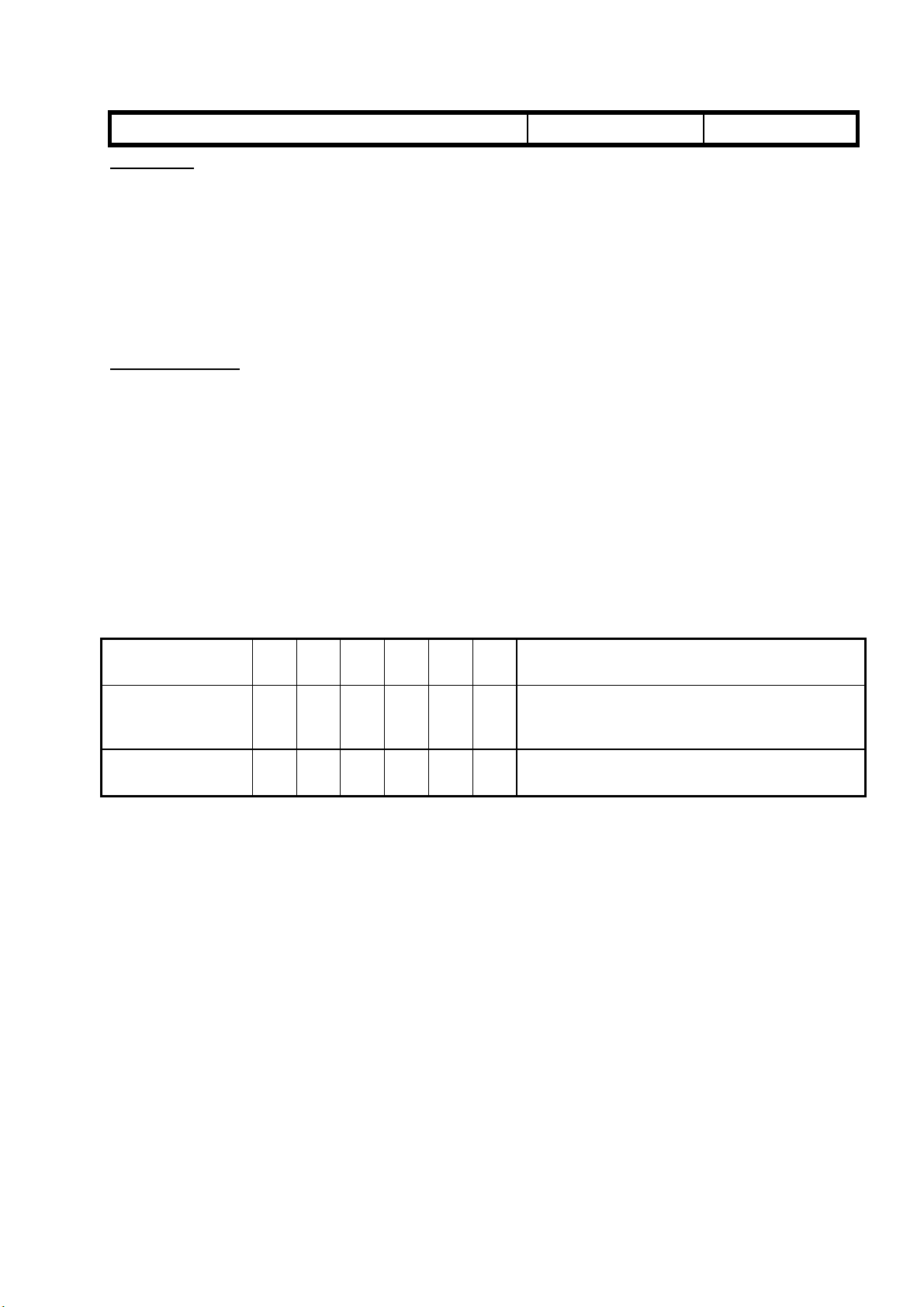
Technical Bulletin No. RTB-001
SUBJECT: Service Manual Correction DATE: 15 Oct. ’96
PAGE: 1 of 7
PREPARED BY: M. Furusawa (FCP)
CHECKED BY:
CLASSIFICATION:
Action Required
Troubleshooting
Retrofit Information
Please correct your service manual as follows, referring to the attached pages already
corrected.
(Corrected or added portions are indicated by thick rectangles.)
Page 1-6
Image Creation : Image Overlay
Basic type does not have this function.
Page 4-31
Dev. Sleeve Cleaning Condition in ACS Mode
The condition "Black mode" should be added to the functional explanation.
Page 4-59
Copier Special Mode
The following remarks have been added:
Revision of service manual
Information only
Other
FROM: 1st Field Information Dept. QAC
MODEL:
LILY
(A172 / A199)
1. Change the setting from "0" to "4" for "Thick 2nd Feed" in SP <1>-2 By-pass Feed in
order to ensure feeding of very thick paper in Special Mode 1.
2. Printer γ correction data in this mode is independent from that in the standard mode.
(ACC results will not be reflected.)
Page 5-12
Step 10 (and 11)
Printer Free Run must be used instead of System Free Run.
- Reason In System Free Run mode, the test pattern will not be written on the drum surface
but the actual scanned image will be written. If we use the System Free Run mode in
this step, a blank image (= image of white paper) will made on the drum surface,
causing too much friction between drum and drum cleaning blade.
Page 5-22
The following procedure should be added to the transfer roller unit:
A Printer Free Run should be performed after replacing the roller lubricant bar and/or
the transfer roller.
Film Projector Unit Page 1
The weight in the Specifications section should be corrected.
Page 2
FUNCTIONS: BASIC MODEL VS EDIT MODEL
LILY RTB-001 P. 2 of 7
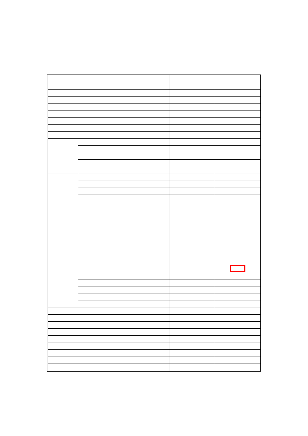
2.2 FUNCTIONS: BASIC MODEL VS EDIT MODEL
This machine comes in two versions. Refer to the following table for features
available on your machine.
Functions Edit type Basic type
Copy Image Density Adjustment (Auto/Manual) ✓ ✓
Auto Color Selection ✓ ✓
Full Color ✓ ✓
Back ✓ ✓
Single Color ✓ ✓
Twin Color ✓ ✓
Original Image Type Selection ✓ ✓
Paper Selection (Auto/Manual) ✓ ✓
Preset R/E ✓ ✓
Reducing/
Enlarging
Shift/Book
Color
Creation
Image
Creation
Color
Adjustment/
Memory
Area Editing ✓ ---Interrupt Copying ✓ ✓
Recall ✓ ✓
Auto Reduce/Enlarge ✓ ✓
Bypass Feed Copying ✓ ✓
Duplex Copying ✓ ✓
Default Setting ✓ ✓
User Tools ✓ ✓
Display Color Full color Black & white
Zoom ✓ ✓
Size Magnification ✓ ✓
Directional Size Magnification ✓ ✓
Poster Mode ✓ ✓
Centering/Cornering ✓ ✓
Margin Adjustment ✓ ✓
Erase ✓ ✓
Single Copies ✓ ✓
Color Conversion ✓ ✓
Color Erase ✓ ✓
Color Background ✓ ✓
Outline ✓ ✓
Positive/Negative ✓ ✓
Shadow ✓ ✓
Mirror ✓ ✓
Slanted ✓ ✓
Image Repeat ✓ ✓
Image Overlay ✓ ---User Color Memory ✓ ✓
Single Color Adjustment ✓ ✓
Color Balance Adjustment ✓ ✓
Color Balance Sample ✓ ✓
Image Adjustment ✓ ✓
1-6
Page 3
LILY RTB-001 P. 3 of 7
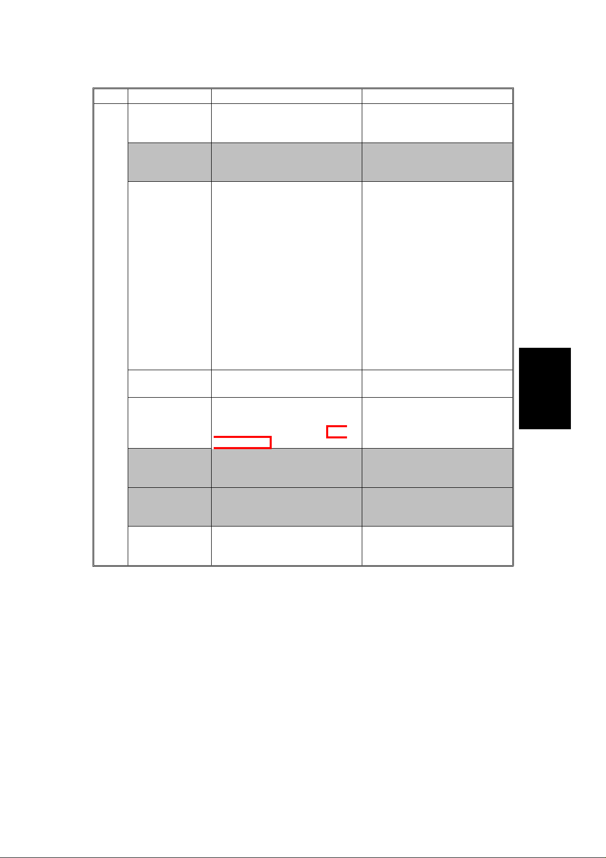
Page Item Function Note
Auto Process
Control Self
check
Toner Supply
Control Mode
Selection
Transfer Bias
Humidity
Selection
<4>
-1
Auto γ
Correction Mode
Dev. Sleeve
Cleaning
Condition in
ACS Mode
TC Correction Selects the TC correction (Vcnt
TC Correction
Threshold
Wire Cleaner
Operation
Factory use only "PID" setting must be used.
Selects toner supply mode. Default: Fuzzy
Selects the output voltage for
the transfer belt and the
transfer roller bias that are used
if the humidity sensor is not
working properly. Use the
setting that best approximates
the machine’s location.
Enable or disable the auto γ
correction mode.
Selects the interval of the
development sleeve cleaning
mode in ACS&DJF mode and
Black mode.
correction) on or off.
Selects to use or not to use the
threshold set in the SP "<1>-4
TC Correction Threshold".
Enables/disables the automatic
charge corona wire/grid
cleaning operation.
SERVICE PROGRAM MODE
"Fuzzy" setting must be used.
Default: Normal
This function is effective under
the following conditions:
1. Humidity sensor is not
working well:
• Output is 0.
• Temperature output is
over 49°C or below 2°C.
• Humidity output is over
98% or below 2%.
2. Humidity sensor is
disconnected.
3. Humidity sensor function is
disabled:
SP<1>P.16 Other SP #13=1
Default: ON
Default: 40 copies
Default: ON
Do not change the setting in
the field.
Default: Reset
Do not change the setting in
the field.
Default: Set (Enabled)
Tables
Service
4-31
Page 4
LILY RTB-001 P. 4 of 7
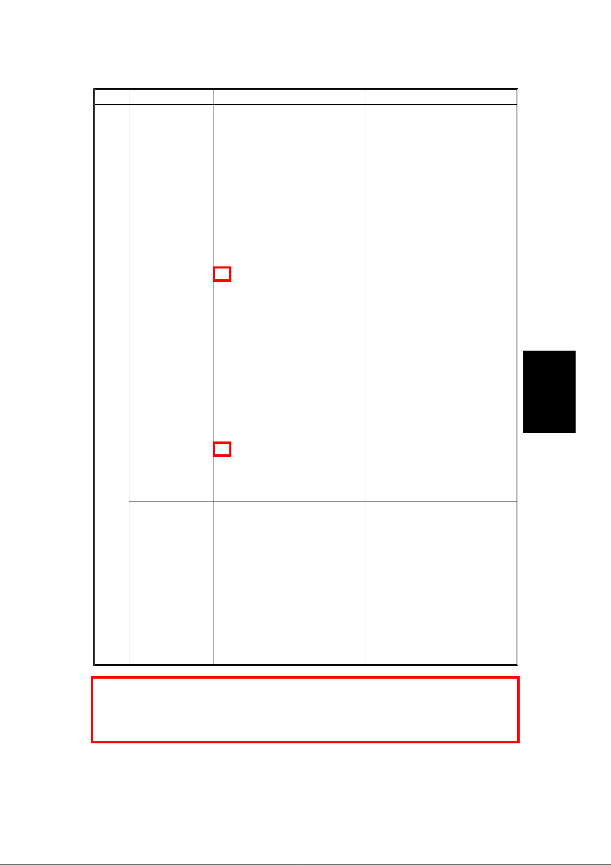
Page Item Function Note
Copier Special
Mode
<10>
-1
Sets the following items for
Copier Special Mode 1 and 2.
<1>SP Adjustment
-1: Lead Edge Registration
(Printing)
-1: Paper Feed Timing
-2: Paper Feed Timing: By-pass
-3: Face side Fusing Temp.
-3: Back side Fusing Temp.
-7: Transfer Roller Bias
(Normal Humidity)
-8: Transfer Roller Coefficient
by Humidity Range
❋1
<4>SP Special Features
-2: Printer γ Correction Data
Rough Adjustment =Letter=
-3: Printer γ Correction Data
Rough Adjustment =Photo=
-4: Printer γ Correction Data
Fine Adjustment
=Printed Photo=
-5: Printer γ Correction Data
Fine Adjustment
=Glossy Photo=
-6: Printer γ Correction Data
Fine Adjustment =Letter=
❋2
SERVICE PROGRAM MODE
This special mode should be
used for user’s special
application paper which does
not have good copy quality with
standard settings.
"<4>-5: Printer γ Correction
Data Fine Adjustment = Glossy
Photo=" is not effective
(indication only).
Special Mode 1 has the
following default for very thick
paper (about 200 g/m2):
<1>-7:Transfer Roller Bias
(Normal Humidity)
Normal Paper
1C: 12002C: 1500
3C: 18004C-L&P: 1500
Thick Paper
1C: 13602C: 1500
3C: 18004C-L&P: 1500
OHP: S&L
1C: 20202C: 2080
3C: 23704C-L&P: 2080
Normal: Back
1C: 12002C: 1700
3C: 19804C-L&P: 1700
Thick: Back
1C: 16002C: 1830
3C: 21304C-L&P: 1830
Tables
Service
Printer Special
Mode
❋1 Change the setting from "0" to "4" for "Thick 2nd Feed" in SP <1>-2 By-pass Feed in
order to ensure feeding of very thick paper in Special Mode 1.
❋2 Printer γ correction data in this mode is independent from that in the standard mode.
(ACC results will not be reflected.)
Sets the following items for
Printer Special Mode 3.
<1>SP Adjustment
-1: Lead Edge Registration
(Printing)
-1: Paper Feed Timing
-2: Paper Feed Timing: By-pass
-3: Face side Fusing Temp.
-3: Back side Fusing Temp.
-7: Transfer Roller Bias
(Normal Humidity)
-8: Transfer Roller Coefficient
by Humidity Range
4-59
This special mode should be
used for user’s special
application paper (Printer
mode) which does not have
good copy quality with standard
settings.
Page 5
DRUM UNIT
LILY RTB-001 P. 5 of 7
6. Open [2]SP Test, page 2.
[B]
[E]
[A]
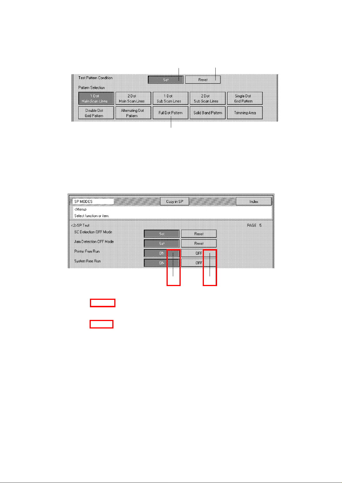
7. Select "Full Dot Pattern" [A] in Pattern selection and select "Set" [B] in
Test Pattern Condition.
8. Touch the "Copy in SP" key and select "Black" copy mode.
9. Touch the "SP MODES" key and open [2]SP Test, page 5.
[C] [D]
10. Start the Printer Free Run by touching "ON" [C] and wait for 6 to 7
minutes.
11. Stop the Printer Free Run by touching "OFF" [D].
12. Open [2]SP Test, page 2 and select "Reset" [E] for Test Pattern
Condition.
13. Wait for 5 minutes and open [2]SP Test, page 4.
14. Perform Process Control Selfcheck by touching "Start".
15. Check the result of Process Control Selfcheck referring to the installation
procedure and exit the SP mode.
16. Perform Auto Color Calibration.
5-12
Page 6
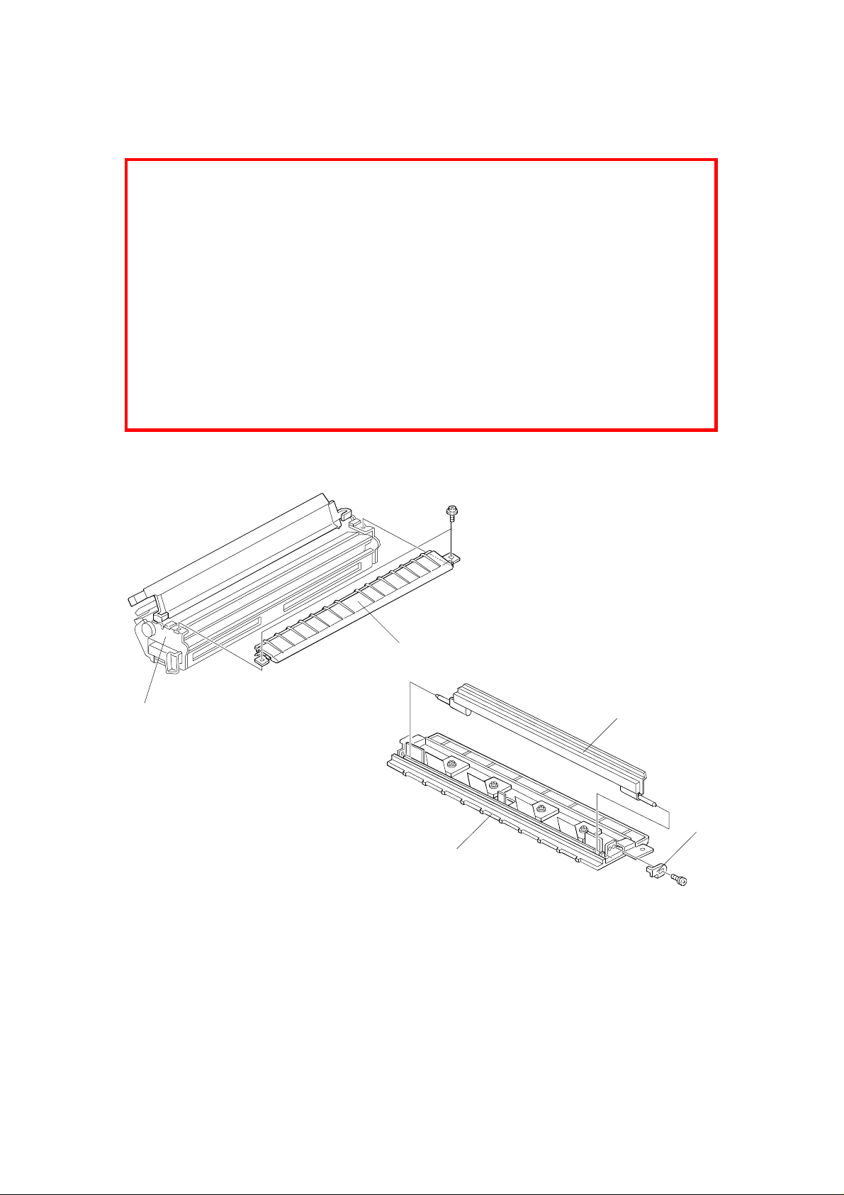
TRANSFER ROLLER UNIT
LILY RTB-001 P. 6 of 7
6. TRANSFER ROLLER UNIT
When completing machine assembly, after changing the roller lubricant bar
and/or the transfer roller, perform steps 3 to 12 of "3.4 INSTALLING A NEW
DRUM". This will cause the new lubricant bar to fully contact the roller. And
also applies the lubricant to the roller surface evenly.
NOTE: 1) If these steps have been done for the new drum, it is unnecessary
to repeat them.
2) If the developer is replaced together with the roller lubricant bar
and/or the transfer roller, the above steps are unnecessary.
(Lubricant is applied to the transfer roller surface during the
developer initialization.)
3) Note that "Printer Free Run" must be used at step 10 of "3.4
INSTALLING A NEW DRUM".
6.1 ROLLER LUBRICANT BAR REPLACEMENT
[A]
[B]
A172R524.wmf
[D]
[C]
[B]
A172R525.wmf
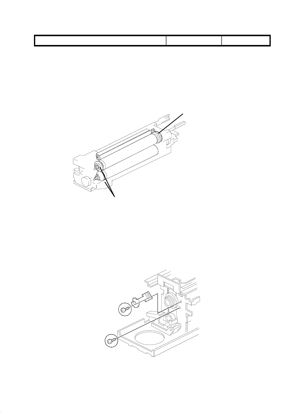
1. Remove the transfer roller unit [A]. (See A109 Transfer Roller Unit
Removal).
2. Remove the transfer roller guide [B] (2 screws).
3. Remove the hook [C] (1 screw) and replace the roller lubricant bar [D].
5-22
Page 7

LILY RTB-001 P. 7 of 7
1. SPECIFICATION
Acceptable Film Types:
• Type: Positive film/Negative film
• Size: 35 mm - Approx. 140 x 210 mm
Others: 45 x 60 mm, 60 x 60 mm,
Max: 142 x 210 mm or 5.6" x 8.2"
• Mount: Yes (Up to 5 frames can be set in
• Strip: Yes (A series of 6 frames can be
Focusing: Fixed/Manual
Effective Film Area:
• 35 mm: Approx. 21.5 x 33.0 mm
SPECIFICATION
60 x 70 mm, 60 x 80 mm,
60 x 90 mm, 4" x 5"
the film holder.)
set in the film holder.)
• Other Sizes: Full Size
Projection Ratio
• 35 mm: Approx. x 6
• Other Sizes: x 1
Copy Image Size
• 35 mm mount:120.8 x 192.7 mm
• 35 mm strip: 129.3 x 198.6 mm
• Other Sizes: Full Size
All the reproduction features of the copier are available.
Power Source: 115 V 60 Hz, more than 1.0 A
220 ~ 240 V 50/60 Hz, more than 0.6 A
Power Consumption: Maximum: less than 185 VA
Dimensions (W x D x H): Projector: 300 x 442 x 212 mm
11.8" x 17.4" x 8.35"
Mirror Unit: 298 x 232 x 50 mm
11.73" x 9.13" x 1.97"
Unit
Film Projector
Weight: Less than 15 kg or 31.9 lb
Remarks: The holder is required for installation.
1
Page 8
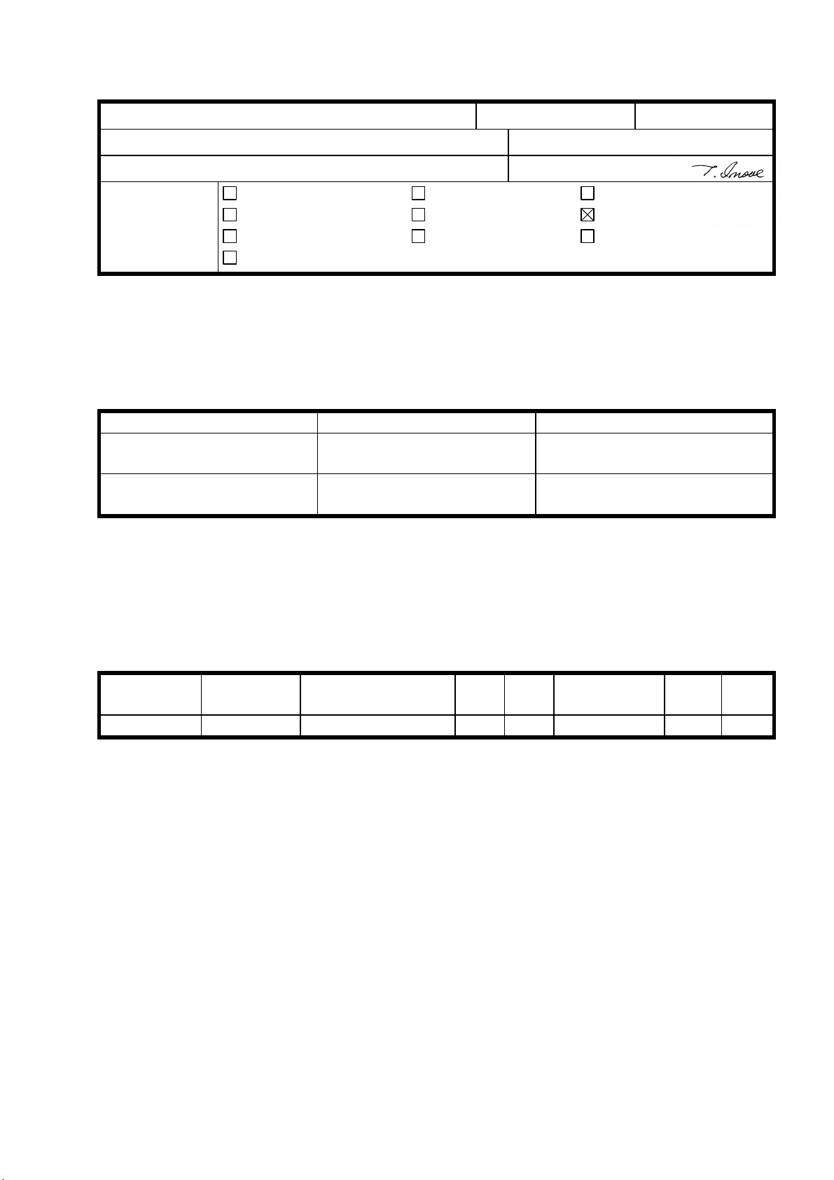
Technical Bulletin No. RTB-002
SUBJECT: Grease for Transfer Belt Unit and Transfer Roller Unit DATE:Oct. 31, ’96
PAGE: 1 of 1
PREPARED BY: N. Kaiya
CHECKED BY:
CLASSIFICATION:
Action Required
Troubleshooting
Retrofit Information
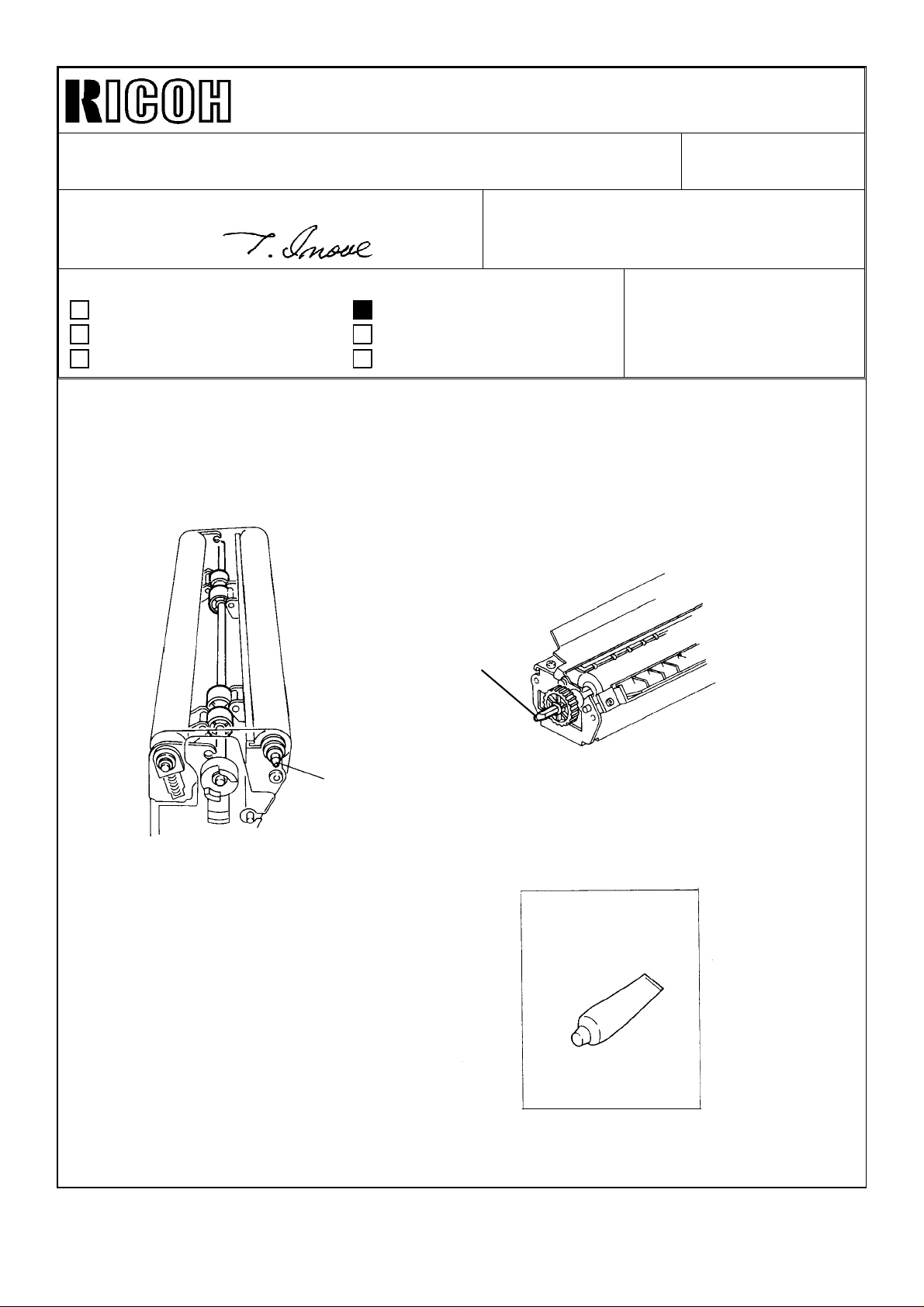
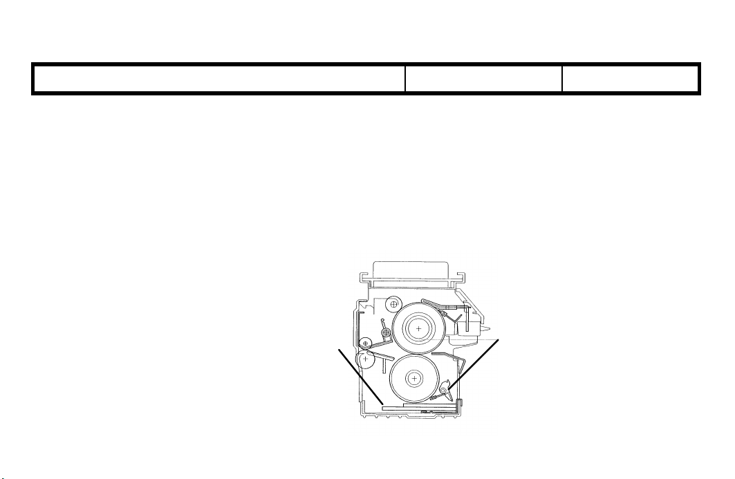
Please use the KS660 grease (P/N G0049668) for lubricating the end of the bias roller
shaft and the end of the transfer roller shaft. The KS660 grease is more conductive than
the 40M grease currently recommended.
Revision of service manual
Information only
Other
Transfer
Roller Shaft
FROM: 1st Field Information Dept. QAC
MODEL: Lily
Belt Bias Roller
Shaft
P/N G004 9668
Grease KS660
Page 9
RICOH Technical Bulletin
Model: Lily Date: 28-Feb-97
Subject: Transfer Belt Tension Release Wedge Prepared by: N. Kaiya
From: QAC 1st Field Information Dept. Checked by: T. Inoue
Classification:
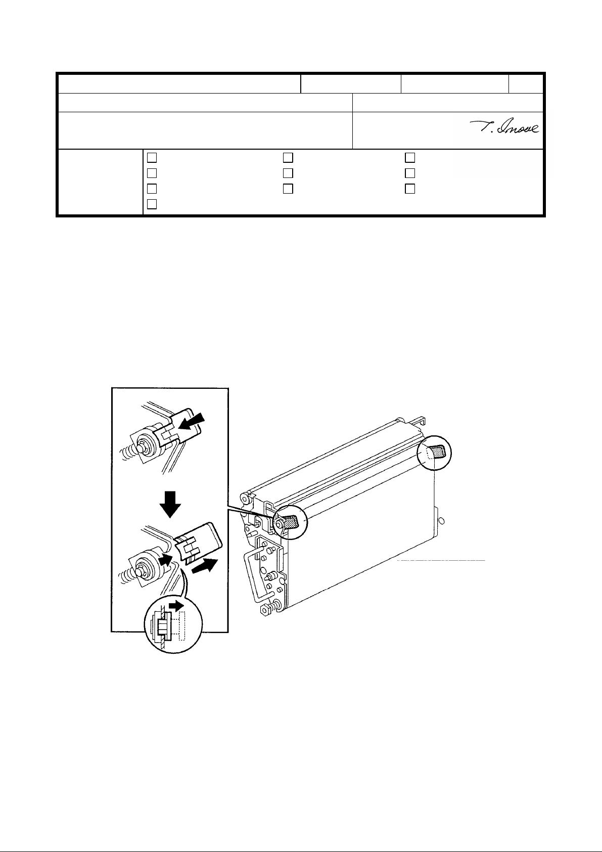
In order to release the tension of the transfer belt during transportation, the Transfer Belt
Release Wedges are installed on the front and rear belt tension roller bearing holders.
Please do not forget to remove the wedges when installing the machine.
To remove the wedge, push the wedge toward the bearing holder and slide it inside
slightly.
Troubleshooting
Mechanical
Paper path
Other ( )
Part information
Electrical
Transmit/receive
No: 003
Action required
Service manual revision
Retrofit information
1/2
Page 10
RICOH Technical Bulletin
Model: Lily Date: 28-Feb-97 No: 003 2/2
MODEL NAME V/ Hz Destination CODE SERIAL NUMBER
Nashuatec C606e
Gestetner 2606e
Savin SDC206E 115V/ 60Hz USA, Canada A172 - 15 5A87010001
Aficio Color 5206 115V/ 60Hz USA, Canada A172 - 17 A7127010001
Nashuatec C606e
Gestetner 2606e
Rex Rotary
CC8606E
Infotec 7316E 220- 240V/
Aficio Color 5206 220- 240V/
Aficio Color 5206 220- 240V/
Lanier 5606 DC 120V60Hz USA A172 - 55 L006070001
Sharp AR-C862 120V60Hz USA A172 - 57 From first
Sharp AR-C862 120V60Hz Europe A172 - 67 From first
Nashuatec C606
Gestetner 2606
Savin SDC206 120V/ 60Hz USA, Canada A199 - 15 5A97010001
Aficio Color 5106 120V/ 60Hz USA, Canada A199 - 17 A7137020001
Nashuatec C606
Gestetner 2606
Rex Rotary CC8606
Infotec 7316 220- 240V/
Aficio Color 5106 220- 240V/
Aficio Color 5106 220- 240V/
Lanier 5606 DC 120V60Hz USA A199 - 55 From first
Sharp AR-C861 120V60Hz USA A199 - 57 From first
Sharp AR-C861 220- 240V/
115V/ 60Hz USA, Canada A172 - 10 AB67020001
220- 240V/
50Hz
50Hz
50Hz
50Hz, 60Hz
115V/ 60Hz USA, Canada A199 - 10 AB4702XXXX
220- 240V/
50Hz
50Hz
50Hz
50Hz, 60Hz
50Hz
Europe, etc. A172 - 22 AB77010001
Europe, etc. A172 - 26 3J80170001
Europe, etc. A172 - 27 A7127010110
Asia, Middle
East
Europe, etc. A199 - 22 AB57010001
Europe etc. A199 - 26 3J70170001
Europe etc. A199 - 27 A7137010001
Asia, Middle
East
Europe A199 - 67 From first
A172 - 29 A7127010184
production
production
A199 - 29 A713702XXXX
production
production
production
Page 11

RICOH Technical Bulletin PAGE: 1/6
Model: Lily Date: 15-Mar-97
Subject: Fusing Unit Prepared by: N. Kaiya
From: QAC 1st Field Information Dept. Checked by: T. Inoue
Classification:
This RTB explains the countermeasure for the OHP offset problem which was found in our
test with paper containing calcium carbonate (Aussedat Rey AR Color). In addition, the
modification related to the countermeasure is explained.
Troubleshooting
Mechanical
Paper path
Other ( )
Part information
Electrical
Transmit/receive
Action required
Service manual revision
Retrofit information
No: 4
PROBLEM
OHP sheets get calcium carbonate on the reverse side in the fusing unit. The problem is
evident under the following conditions.
1. When Folex X-356 OHP film is used.
2. Paper containing a large amount of calcium carbonate is used prior to making copies
with OHP film.
3. After a continuous single-color copy run using paper with calcium carbonate (according
to our test, the problem is evident on the OHP film copied after more than 20 singlecolor A3 copies are made).
CAUSE
The calcium carbonate from the paper is deposited on the surface of the pressure roller
and offset to the back side of the OHP sheet.
The calcium carbonate deposits on the surface of the pressure roller when there is less
silicone oil on the surface of the pressure roller than usual. This condition only exists
after a long series of single-color copies. This is because when making single-color
copies, the sheets of copy paper are fed to the fusing unit with only a small interval
between them. When making full-color copies, the fusing unit idles during four
development cycles, so the pressure roller has sufficient time to receive silicone oil on its
surface.
Page 12
RICOH Technical Bulletin PAGE: 2/6
Model: Lily Date: 15-Mar-97
No: 4
COUNTERMEASURE
A pressure roller cleaning blade and a pressure roller oil pad will be added in place of the
pressure roller cleaning roller. The pressure roller cleaning roller will be removed. The
pressure roller cleaning blade removes calcium carbonate on the pressure roller. It also
removes excess silicone oil from the pressure roller. The silicone oil applied on the
pressure roller surface prevents the pressure roller cleaning blade from making vibration
noise.
Pressure Roller
Oil Pad
Pressure Roller
Cleaning Blade
Page 13
RICOH Technical Bulletin PAGE: 3/6
Model: Lily Date: 15-Mar-97
No: 4
Gear
The addition of cleaning blade and oil pad applies excess load to the pressure roller
which may result in copy quality problems such as mimizu image. To prevent this
problem, gears are added to the front of the hot roller and pressure roller, which provide
drive to the pressure roller. At the same time, the 61Z Gear has been changed to a 62Z
Gear to compensate for the slight increase in the paper speed caused by providing drive
to the pressure roller. To install the gears, the hot roller and the pressure roller have
been modified with interchangeability x/o.
Gear 61z→62z
Newly Added
The screw holding the front fusing lamp holder has been changed to a shorter (M4 x 5)
screw to prevent contact with the hot roller gear. The same screw type has been added to
secure the ball bearing at the front of the hot roller. This is necessary to maintain the
position of the hot roller gear and to ensure meshing with the pressure roller gear.
Page 14
RICOH Technical Bulletin PAGE: 4/6
Model: Lily Date: 15-Mar-97
No: 4
Modification Cut-in
This modification has been made to the February production run of machines destined for
the European market, since paper with high calcium carbonate content is seen mostly in
the European market. The modification to apply drive to the pressure roller has been
made to all models to minimize the possibility of copy quality problems such as mimizu
image. For the cut-in serial number, please refer to MB No.6.
Replacement Procedure
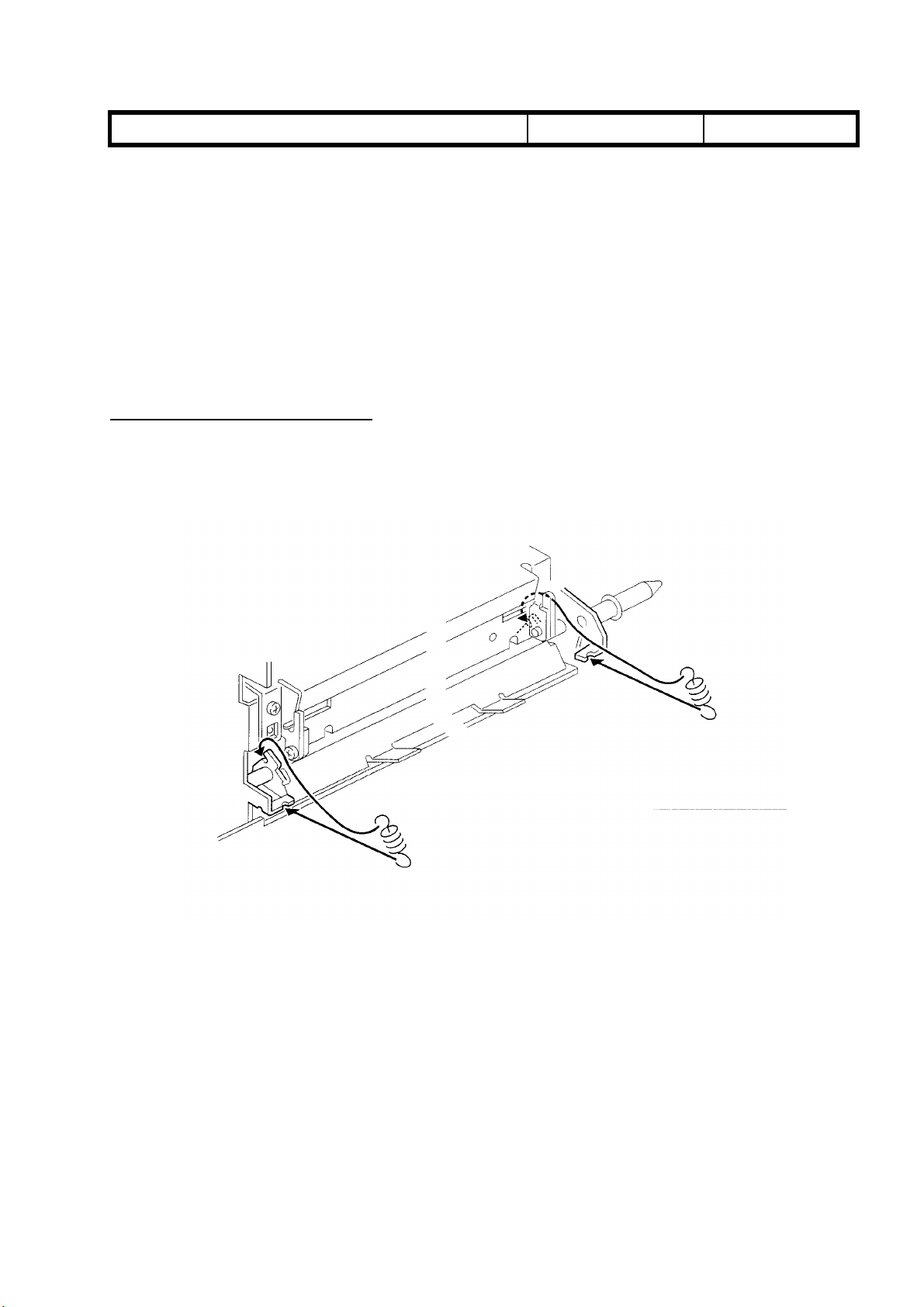
Pressure Roller Cleaning Blade
1. Remove the two pressure roller cleaning blade springs.
2. Remove the cleaning blade by sliding it out from the pins on the front and rear fusing
unit side frames.
Page 15
RICOH Technical Bulletin PAGE: 5/6
Model: Lily Date: 15-Mar-97
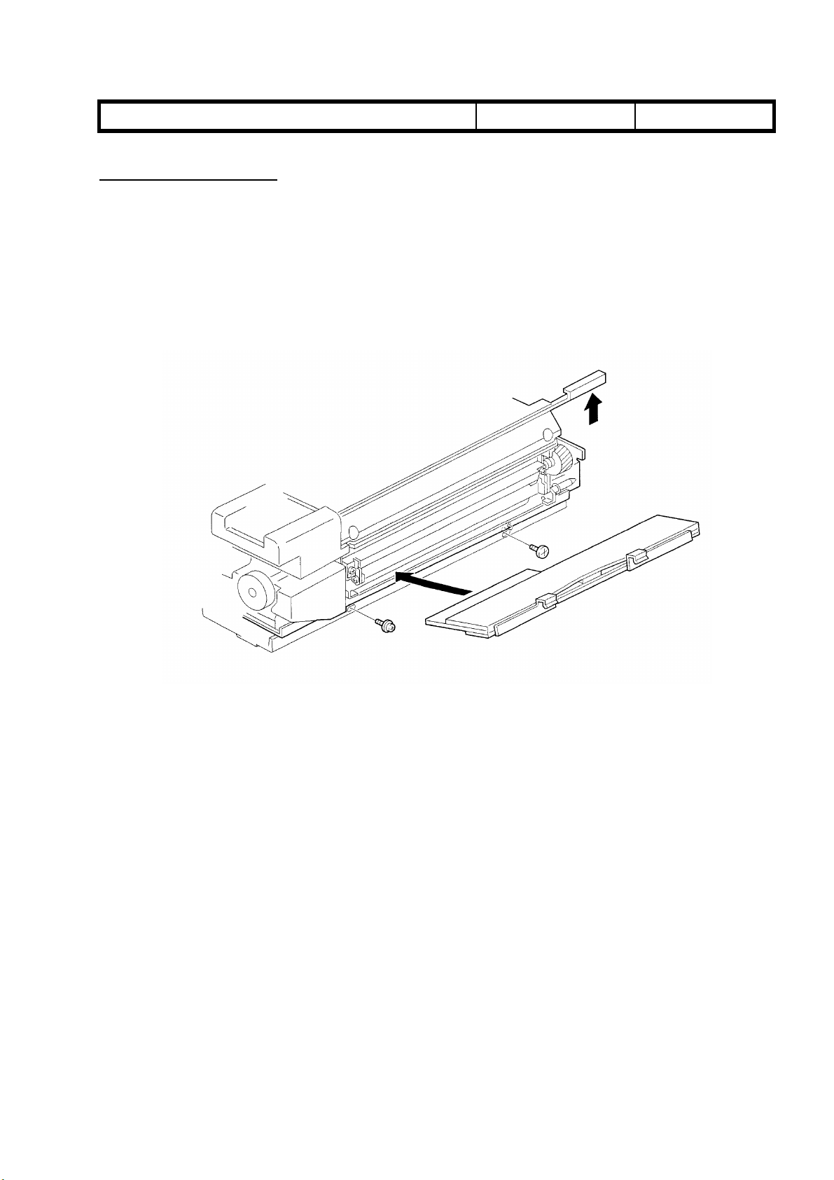
Pressure Roller Oil Pad
1. Remove the pressure roller cleaning blade.
2. Lift the two hooks of the oil pad and pull out the oil pad.
Note
When installing the new oil pad, the oil pan may be removed for easier installation
No: 4
Page 16
RICOH Technical Bulletin PAGE: 6/6
Model: Lily Date: 15-Mar-97
Hot Roller
Please change step no. 11 in the hot roller replacement procedure (DFC-α Service
Manual page 5-101) as follows;
11. Remove the hot roller gear - 60Z, hot roller drive gear [I], heat isolating bushings [J],
and ball bearings [K] (2 screws).
Pressure Roller
Please change step no.4 in the pressure roller replacement procedure (Page 5-103 in the
DFC-α Service Manual) as follows.
4. Slide the pressure roller [A] toward the rear of the fusing unit and pull it out of the rear
bearing. Lift the pressure roller from the front side and pull off the front bearing [B].
No: 4
PM Table
The pressure roller and the pressure roller oil pad pads are PM parts. Please add them to
the PM table in your Service Manual.
ITEM EM 40K80K120K160K200KNOTE
Pressure Roller
Cleaning Blade
Pressure Roller Oil
Pad
C R C R C Suitable Solvent
Apply silicone oil to the edge after cleaning or
replacement.
R R R R R
Troubleshooting Procedure for Machines before Modification
If the problem is found with machines manufactured before the modification, please
advise the customer to:
• Wipe off the calcium carbonate from the OHP sheet
• Use 3M OHP sheets.
Page 17
RICOH Technical Bulletin PAGE: 1/2
Model: Lily Date: 15-Apr-97
No: 5
Subject: Nip Band Width Prepared by: N.Kaiya
From: QAC 1st Field Information Dept. Checked by: T. Inoue
Classification:
Troubleshooting
Mechanical
Paper path
Other ( )
Part information
Electrical
Transmit/receive
Action required
Service manual revision
Retrofit information
The nip band width of the fusing unit has been changed as follows. This is to minimize
the possibility of mimizu image.
Location New Standard Old Standard
Both Edges
9.25±0.25 mm 9.5±0.5 mm
(20 mm from the edges)
Center
9.0±2.5 mm 9.0±0.5 mm
(confirmation reference)
To facilitate this adjustment on the production line, the pressure spring has been changed
to a weaker type as follows. To distinguish the new and the old spring, its color has been
changed from black to silver.
Old part New part Description Qty Int Destination Page Index
number number
AA063355 AA063562 Pressure Spring 2-2 X/O 85 21
It is not necessary to readjust the nip band width of the machines in the field. If any
problem related to the nip band is found, please check it against the new standard and
adjust if necessary. However, it may not be possible to achieve the new adjustment
standard with the old pressure spring.
Please refer to the following table for the cut in serial number.
Page 18

RICOH Technical Bulletin PAGE: 2/2
Model: Lily Date: 15-Apr-97
MODEL NAME V/ Hz DESTINATION CODE SERIAL
Nashuatec C606e
Gestetner 2606e
Savin SDC206E 120V/ 60Hz USA, Canada A172 - 15 5A86110001
Aficio Color 5206 120V/ 60Hz USA, Canada A172 - 17 A7126110001
Nashuatec C606e
Gestetner 2606e
Rex Rotary
CC8606E
Infotec 7316E 220- 240V/
Aficio Color 5206 220- 240V/
Aficio Color 5206 220- 240V/
Lanier 5606 DC 120V60Hz USA A172 - 55 L006110001
Sharp AR-C862 120V60Hz USA A172 - 57 S167030001
Sharp AR-C862 120V60Hz Europe A172 - 67 S167020001
Nashuatec C606
Gestetner 2606
Savin SDC206 120V/ 60Hz USA, Canada A199 - 15 5A96110001
Aficio Color 5106 120V/ 60Hz USA, Canada A199 - 17 A7136110001
Nashuatec C606
Gestetner 2606
Rex Rotary CC8606
Infotec 7316 220- 240V/
Aficio Color 5106 220- 240V/
Aficio Color 5106 220- 240V/
Lanier 5606 DC 120V60Hz USA A199 - 55 L0077010001
Sharp AR-C861 120V60Hz USA A199 - 57 S167030046
Sharp AR-C861 220- 240V/
120V/ 60Hz USA, Canada A172 - 10 AB67020001
220- 240V/
50Hz
50Hz
50Hz
50Hz, 60Hz
115V/ 60Hz USA, Canada A199 - 10 AB4612xxxx
220- 240V/
50Hz
50Hz
50Hz
50Hz, 60Hz
50Hz
Europe, etc. A172 - 22 AB76110001
Europe, etc. A172 - 26 3J81160001
Europe, etc. A172 - 27 A7126110046
Asia, Middle
East
Europe, etc. A199 - 22 AB56110001
Europe etc. A199 - 26 3J71160001
Europe etc. A199 - 27 A7136110041
Asia, Middle
East
Europe A199 - 67 S167020023
A172 - 29 A7126110091
A199 - 29 A713612xxxx
No: 5
NUMBER
Page 19

RICOH Technical Bulletin PAGE: 1/2
Model: Lily Date: 31-Aug-97
No: 6
Subject: Cyan Toner Scattering in Printer Mode Prepared by: N.Kaiya
From: QAC 1st Field Information Dept.
Classification:
Troubleshooting
Mechanical
Paper path
Other ( )
Part information
Electrical
Transmit/receive
Action required
Service manual revision
Retrofit information
This RTB is to explain the countermeasure to the cyan toner scattering in print mode.
Problem
Cyan toner scattered around the text and edges of solid image areas in print mode.
Cause
The PTL light (red light) is blocked by the cyan toner. The electrical potential of the image
area does not drop, while the potential on the bare drum surface drops. As a result, some
toner is attracted to the bare drum surface. See the following diagram.
Before PTL Emission After PTL Emission
VD
toner toner
VL
bare drum
(VD drops to the bare drum potential level, but VL does not drop to the same level since
PTL light is blocked by cyan toner.)
The problem is evident when the amount of toner on the drum (M/A) is large. The problem
is seen only in the print mode, since the maximum amount of toner on the drum is higher
compared to that of copy mode.
Compared to the DFC-α, Lily has higher M/A for cyan. This caused the level of cyan toner
scattering to become worse than in the DFC-α.
Page 20

RICOH Technical Bulletin PAGE: 2/2
Model: Lily Date: 31-Aug-97
Countermeasure
1. The PTL has been changed to emit stronger light.
Part Number A0305243 à A3995243
2. The ACC target for the printer mode has been modified to decrease the maximum
amount of toner on the drum. (IPU ROM revision G)
Model V/Hz Destination Code Serial Number
Nashuatec C606e
Gestetner 2606e
Savin SDC206E 120V/60Hz USA,Canada A172-155A87030001
Aficio Color 5206 120V/60Hz USA,Canada A172-17 A7127030001
Nashuatec C606e
Gestetner 2606e
Rex Rotary CC8606E
Infotec 7316E 220-240V/50Hz Europe,etc. A172-26 3J80370001
Aficio Color 5206 220-240V/50Hz Europe,etc. A172-27 A7127030266
Aficio Color 5206 220-240V/50Hz,60HzAsia,Middle East A172-29 A7127030356
Lanier 5606 DC 120V/60Hz USA A172-55L0067030136
Sharp AR-C862 120V/60Hz USA A172-57S167030001
Sharp AR-C862 220-240V/50Hz Europe A172-67 S167030041
Nashutec C606
Gestetner 2606
Savin SDC206 120V/60Hz USA,Canada A199-15 5A97030001
Aficio Color 5106 120V/60Hz USA,Canada A199-17 A7137030001
Nashuatec C606
Gestetner 2606
Rex Rotary CC8606
Infotec 7316 220-240V/50Hz Europe,etc. A199-26 3J70370001
Aficio Color 5106 220-240V/50Hz Europe,etc. A199-27 A7137030066
Aficio Color 5106 220-240V/50Hz,60HzAsia, Middle EastA199-29 A7137080121
Lanier 5606 DC 120V/60Hz USA A199-55L0077030036
Sharp AR-C861 120V/60Hz USA A199-57S167030046
Sharp AR-C861 220-240V/50Hz Europe A199-67 S167030076
120V/60Hz USA,Canada A172-10 AB67030001
220-240V/50Hz Europe,etc. A172-22 AB77030001
120V/60Hz USA,Canada A199-10 AB4703xxxx
220-240V/50Hz Europe,etc. A199-22 AB57030001
No: 6
Note
This problem can be eliminated by disconnecting the PTL, but in this case, magenta toner
blasting in 2C mode may occur. This is because the intention of the PTL is to cause a little
cyan toner scattering which will repel the scattered magenta toner.
Page 21

T
echnical
B
ulletin
MB Correction
Reissue date:
The items in bold italic have been corrected or added.
Model:
Lily
15-Sep-97
Date:
31-Aug-97
No:
PAGE: 1/1
7
Subject:
From:
Classification:
Problem
Horizontal lines (banding) occur at random pitches, most noticeably in half-tone images.
Removal/reinstallation of the development unit or replacement of the development sleeve
have been effective but recurrences have been reported.
Countermeasures
Install the side sleeve shaft gear of the magenta sleeve assembly into the ball bearing
(08053596) as shown below. Set the lock washer (H0014219) to secure the ball bearing.
Magenta Banding
QAC 1st Field Information Dept.
Troubleshooting
Mechanical
Paper path
Other ( )
Part information
Electrical
Transmit/receive
Prepared by:
Ball Bearing
N.Kaiya
Action required
Service manual revision
Retrofit information
Lock Washer
Rear Shaft
The part number of the magenta development sleeve has been changed as follows.
A1723214 Æ A1723213
For the field units, please add the ball bearing and the lock washer when the problem is
found. Please refer to the Modification Bulletin for cut-in serial number of the modification
to the production.
Cause
A sudden drop in conductivity between the development sleeve and the sleeve surface
during the rotation of the magenta development sleeve may result in horizontal lines
appearing at random pitches. The most likely reason why this only occurs with magenta is
that it is the furthest from the core of the drum shaft and thus the thrust play is
proportionately larger.
Page 22

RICOH Technical Bulletin PAGE: 1/1
Model: Lily Date: 31-Aug-97
No: 8
Subject: High Toner Density in Low Humidity Environment Prepared by: N.Kaiya
From: QAC 1st Field Information Dept.
Classification:
Troubleshooting
Mechanical
Paper path
Other ( )
Part information
Electrical
Transmit/receive
Action required
Service manual revision
Retrofit information
Problem
Under low humidity conditions such as during winter in continental areas, the toner
density rises quickly within 1K copies after developer replacement, and image density is
high and dirty background appears. This is particularly noticeable with black and cyan.
Cause
Due to the drop in the charge of the developer over time, it is necessary to change Vcnt if
the developer gamma surpasses a certain value, to prevent the image density from
increasing. However, the charge for this type of toner has a tendency to plummet in hightemperature/low-humidity environments, so this problem occurs more frequently indoors
during the winter. Since Vcnt cannot keep up with the speed with which the charge drops,
the image density rises over short periods of time.
Countermeasures
1. Replace the developer (all colors).
2. Adjust the toner density sensor initial setting until the image density is correct.
3. Access SP Mode; SP Adjustment: P. 16: Other SP Adjustments, and set No1 from
00000 to 00001.
Reason for Alteration
The above SP Mode turns on Vcnt (Correction by number of scans) for toner density
control. When this correction is turned on, Vcnt decreases by 1 every 100 scans and ends
after 600 scans (-6). However, for cyan the correction is only up to 500 scans (-5). All
colours are controlled separately.
Notes
1. It does not matter when Vcnt is turned on after the developer has been changed. The
result will be the same if it is done within 100 scans after the toner density sensor initial
setting.
2. At the time of the toner density sensor initial setting, the correction counter is reset to 0.
3. If the Vcnt correction is turned on without developer replacement, there is the
possibility that the image density will gradually become lighter.
4. In a high-humidity environment, there is a possibility of over-correction (low toner
density leads to low image density) so please turn this Vcnt correction off.
Page 23

RICOH Technical Bulletin PAGE: 1/2
Model: Lily Date: 31-Aug-97
No: 9
Subject: Firefly Spots due to Carrier Prepared by: N.Kaiya
From: QAC 1st Field Information Dept.
Classification:
Troubleshooting
Mechanical
Paper path
Other ( )
Part information
Electrical
Transmit/receive
Action required
Service manual revision
Retrofit information
Problem
Firefly spots (light spots) in solid or halftone image areas.
Cause
Unstable carrier particles attracted to the drum surface prevent toner around it from being
transferred to the transfer belt, resulting in light spots on the copy.
Note
Similar image problems may occur with condensed toner attracted to the drum surface.
The cause of this problem is differrent and cannot be corrected with the following
procedure. In most cases, the problem can be distinguished by the presence of condensed
toner at the center of the light spot.
Solution
Follow the steps below to remove the unstable carrier in the developer.
1. Open SP mode 2-2 (Test Pattern Condition), set the test pattern condition and select
the full dot pattern.
2. Make an A3 single color copy(s) using the color(s) which has light spots.
3. Open SP mode 3-3 (Drum Potential Control Output) and note the actual VB value of the
color which has light spots.
4. Open SP mode 1-4 (Setting for P-con Off Mode) and input the actual VB
value + 200 to the VB for the color(s) which has light spots. Input actual VB value +
355 to the VG of the color(s) which has light spots.
Example: If VB actual is –300V, inpu t –500V to VB and –655V to VG.
5. Open SP mode 4-1 (Auto Process Control Selfcheck ) and select reset.
Page 24

RICOH Technical Bulletin PAGE: 2/2
Model: Lily Date: 31-Aug-97
6. Make 10 A3 single color copies with the color(s) which has light spots.
7. Open SP mode 4-1 (Auto Process Control Selfcheck) and select PID. Open SP mode 2-
2 (Test Pattern Condition), and reset the test pattern condition.
8. Open SP mode 3-1 (Toner Density). Make 10 A3 full color copies while observing the Vt
of the color(s) which has light spots. When Vt is within ±0.2 of Vref, cancel the
remaining copies.
9. Open SP mode 1-4 (Setting for P-con Off Mode) and lower the VB and VG settings by
100 for the color(s) which has light spots.
10. Open SP mode 4-1 (Auto Process Control Selfcheck ) and select reset.
11. Open SP mode 2-2 (Test Pattern Condition), set the test pattern condition and select the
full dot pattern.
12. Make an A3 single color copy(s) using the color(s) which has light spots. If copy
quality is improved to an acceptable level, open SP mode 1-4 (Setting for P-con Off
Mode) and return VB and VG to the default settings.
No: 9
13. Open SP mode 4-1 (Auto Process Control Selfcheck) and select PID. Make one A3
single color copy with the color(s) which has light spots. Open SP mode 2-2 (Test
Pattern Condition), and reset the test pattern condition.
14. If some light spots still remain on the copy made in step 12, open SP mode 1-5
(Transfer Belt Bias ) and increase the transfer belt bias by 200. (Transfer belt bias can
be increased further, but not by more than 400.)
15. If the copy quality is not acceptable with the sample made in step 12, repeat the
procedure from step 4.
Page 25

RICOH Technical Bulletin PAGE: 1/1
Model: Lily Date: 31-Aug-97
No: 10
Subject: Blanking at the Trailing Edge of Solid Image Areas Prepared by: N.Kaiya
From: QAC 1st Field Information Dept.
Classification:
Troubleshooting
Mechanical
Paper path
Other ( )
Part information
Electrical
Transmit/receive
Action required
Service manual revision
Retrofit information
Problem
Blanking occurs at the trailing edge of a solid-image area when there is a black frame. The
problem does not happen with the grid pattern from the copier. The width of the blanking is
about 0.1 to 0.2 mm.
Black frame Blanking
Leading Edge
Solid image
Countermeasures
1. Adjust the tension of the transfer belt timing belt and the drum drive timing belt.
2. SP Adjustment: P. 1: Transfer Belt Speed Adjustment (Default: 0)
Increase the setting by +1~+2.
3. Check the copy quality.
Cause
In machines in which the relative speed difference between the drum and the transfer
belt is quite large, the electrostatic absorption at the time of belt transfer causes partial
shifting of the image. The difference in the position shift of the grid pattern and the
controller image is probably a result of direct contact area difference between the
drum and the belt of the toner image.
Page 26

RICOH Technical Bulletin PAGE: 1/2
Model: Lily Date: 31-Aug-97
No: 11
Subject: Jagged Image in Printer Mode Prepared by: N.Kaiya
From: QAC 1st Field Information Dept.
Classification:
Troubleshooting
Mechanical
Paper path
Other ( )
Part information
Electrical
Transmit/receive
Action required
Service manual revision
Retrofit information
Problem
The outline of characters is not straight (jagged) in printer mode. The problem does not
happen with the prints made in letter mode.
Cause
In photo mode, 2x1 dot dither processing is applied to all images including text. If the
copier’s condition is tending to output high (dark) image density, it will be adjusted by 2x1
dot dither processing, resulting in a jagged image. The problem is noticeable especially
when calibration targets with low IDmax are used.
Solution
Lower the copier’s image density by the following procedure
1. Open SP Mode 8-4 (Printer γ Correction Data Fine Adjustment =Contone= ). Check
IDmax of the color showing jagged image.
2. Open SP Mode 1-4 (Toner Max M/A Target). Input 0.800 if the IDmax checked above is
4. Input 0.700 if the IDmax checked above is 3 or below.
3. Wait 5 minutes. Open SP Mode 2-4 and perform the Process Control Self Check.
4. Open SP Mode 3-2 and confirm that the pointer table is not 00.
Note:If the pointer table is 00, the machine selected the default pointer table since the
Toner Max M/A Target is lowered too much. Try with a higher Toner Max M/A Target.
5. Perform printer ACC.
6. Check the print quality and if it is not satisfactory, go back to step 1.
Note : For SP Mode 1-4 (Toner Max M/A Target), you may input a lower value than
those described above, but please make sure that the selected pointer table is not 00.
Page 27

RICOH Technical Bulletin PAGE: 2/2
Model: Lily Date: 31-Aug-97
Modification of Software for Easier Adjustment
With the current main board ROM, the SP Mode 1-4 (Toner Max M/A Target) adjusts the
M/A target for all colors at the same time. The ROM will be modified to make this
adjustment independent for each color. With the new software, the toner maximum M/A
target for each color is allocated in the SP Mode as follows.
Black SP Mode 1-4 Toner Max M/A Target (same as now)
Cyan SP Mode 1-16 Other SP Mode No.15
Magenta SP Mode 1-16 Other SP Mode No.16
Yellow SP Mode 1-16 Other SP Mode No.17
No: 11
Page 28

RICOH Technical Bulletin PAGE: 1/1
Model: Lily Date: 31-Aug-97
No: 12
Subject: Sorter Roller Mark Prepared by: N.Kaiya
From: QAC 1st Field Information Dept.
Classification:
Troubleshooting
Mechanical
Paper path
Other ( )
Part information
Electrical
Transmit/receive
Action required
Service manual revision
Retrofit information
Problem
After installating the sorter, roller marks may appear on the backside of the copy during the
copy run test. This problem cannot be solved by cleaning the rollers but will disappear
after approximately 1K copies.
Cause
The line velocity of the copier and the sorter sometimes do not match.
Action
1. Remove the rear cover of the sorter.
2. Turn on #2 of DPS100 and adjust VR101 until LED102 is lit. Then slowly turn VR101
clockwise until LED102 is no longer lit. Now turn VR101 clockwise one notch.
3. Turn off #2 of DPS100 and perform another copy run test. Check for the roller marks.
If the marks remain, turn VR101 clockwise one more notch.
Note
1. It is not necessary to adjust the high motor speed.
2. Since the reaction time of LED102 in response to the rotation of the VR is slow, wait for
2~3 seconds before checking to see if it is lit.
3. If the motor make a strange noise as it rotates, this may lead to unstable control. If this
happens, turn VR101 counterclockwise to the original position.
Page 29

T
Model:
Lily
echnical
ulletin
B
Date:
15-Dec-97
No:
PAGE: 1/2
13
Subject:
From:
Classification:
The following modification has been made to the fusing unit to reduce hot roller damage by
the stripper pawls when a paper jam occurs in the fusing unit. These improvements are
made from October ’97 production machines. For the cut-in serial number, please refer to
the Modification Bulletins.
Hot Roller Stripper Slider
The hot roller stripper slider has been modified to prevent the stripper from being pushed
too hard into the hot roller by jammed paper. The part number has been changed from
A1094204 to A1724205.
Hot Roller Damage
QAC Field Information Dept.
Troubleshooting
Mechanical
Paper path
Other ( )
Part information
Electrical
Transmit/receive
Prepared by:
Action required
Service manual revision
Retrofit information
N.Kaiya
When replacing the slider, loosen the two screws and remove the hot roller stripper
springs as shown below. Apply some grease to the slider in the area where it contacts the
front and rear frame of the paper exit unit.
Page 30

T
Model:
Stripper Holder
Stripper holders are newly added to prevent the hot roller strippers from coming off of their
bracket because of jammed paper.
Part Number A1724203
Lily
echnical
B
ulletin
Date:
15-Dec-97
No:
PAGE: 2/2
13
Page 31

T
Model:
Lily
echnical
B
ulletin
Date:
15-Dec-97
No:
PAGE: 1/3
14
Subject:
From:
Classification:
This RTB explains the modification of Lily main board ROMs.
The Main board ROMs have been modified as follows.
IC Main Control 10 : A1725114D Æ A1725114E (Total Sum 0A94)
IC Main Control 20 : A1725115D Æ A1725115E (Total Sum 3293)
IC Main Control 30 : A1725129D Æ A1725124E (Total Sum A90D)
Main Board ROM Revision E
QAC Field Information Dept.
Troubleshooting
Mechanical
Paper path
Other ( )
Part information
Electrical
Transmit/receive
Prepared by:
Contents of the Modification
N.Kaiya
Action required
Service manual revision
Retrofit information
1. Countermeasure for SC130 (Scanner Start Abnormal)
SC130 is indicated for the second or subsequent copies of a multicopy run only when 11 x
8-½ sideways, single color, and 210% enlargement are selected.
The CPU is controlling the scanner start timing to achieve the specified copy speed. If for
some reason, return of the scanner to home position is delayed, the scanner control PCB
receives a scanner start signal from the main control PCB before it receives the scanner
home position signal. In this case, SC130 is generated.
In enlargement mode, the scanner requires more time for scanning. To compensate, the
copy speed for single color, 11 x 8 1/2 is reduced to 29 cpm at 211% enlargement and
higher. This problem happens only at this enlargement because it is the largest ratio
before cpm is reduced to 29. To solve this problem, the copy speed will be reduced to 29
cpm at 151% enlargement and above.
This problem is found with a few users in the US market.
2. Jagged Image in Printer Mode
To solve the jagged image problem, sometimes it is necessary to adjust the Toner
Maximum M/A Target. (Please refer to RTB No.11)
Page 32

T
Model:
With the old main board ROM, the SP Mode 1-4 Toner Max M/A Target adjusts the M/A
target for all colors at the same time. The ROM has been modified to make this adjustment
independent for each color. With the new software, the toner maximum M/A target for
each color is allocated in the SP Mode as follows.
Black SP Mode 1-4 Toner Max M/A Target
Cyan SP Mode 1-16 Other SP Mode No.15
Magenta SP Mode 1-16 Other SP Mode No.17
Yellow SP Mode 1-16 Other SP Mode No.18
Lily
echnical
B
ulletin
Date:
15-Dec-97
No:
PAGE: 2/3
14
NOTE:
3. Countermeasure for SC353 (Cyan TD Sensor initial setting error)
This problem was reported from the production line.
The detection timing for SC353 was sometimes too early, so that the TD sensor output
might not be stabilized yet, resulting in SC353. To prevent this prob lem, detection timing
has been delayed.
4. Countermeasure for SC321 in Printer Mode
A software problem related to signal exchange between the main board and the IPU
resulting in SC321 generation has been corrected.
Please correct the table in RTB 11. The SP Mode No. for Magenta is No.17 and
SP Mode No. for Yellow is No.18 as shown in the above table.
Page 33

T
Model:
Lily
echnical
B
ulletin
Date:
15-Dec-97
No:
PAGE: 3/3
14
Modification cut-in
The modification will be made from the December ’97 production machines.
Model V/Hz Destination Code Serial Number
Nashuatec C606e
Gestetner 2606e
Savin SDC206E 120V/60Hz USA,Canada A172-15
Aficio Color 5206 120V/60Hz USA,Canada A172-17
Aficio Color 5206 220V/60Hz Taiwan A172-19
Nashuatec C606e
Gestetner 2606e
Rex Rotary CC8606E
Infotec 7316E 220-240V/50Hz Europe,etc. A172-26
Aficio Color 5206 220-240V/50Hz Europe,etc. A172-27
Aficio Color 5206 220-240V/50Hz,60Hz Asia,Middle East A172-29
Lanier 5606 DC 120V/60Hz USA A172-55
Sharp AR-C862 120V/60Hz USA A172-57
Sharp AR-C862 220-240V/50Hz Europe A172-67
Nashutec C606
Gestetner 2606
Savin SDC206 120V/60Hz USA,Canada A199-15
Aficio Color 5106 120V/60Hz USA,Canada A199-17
Nashuatec C606
Gestetner 2606
Rex Rotary CC8606
Infotec 7316 220-240V/50Hz Europe,etc. A199-26
Aficio Color 5106 220-240V/50Hz Europe,etc. A199-27
Aficio Color 5106 220-240V/50Hz,60Hz Asia, Middle East A199-29
Lanier 5606 DC 120V/60Hz USA A199-55
Sharp AR-C861 120V/60Hz USA A199-57
Sharp AR-C861 220-240V/50Hz Europe A199-67
120V/60Hz USA,Canada A172-10
220-240V/50Hz Europe,etc. A172-22
120V/60Hz USA,Canada A199-10
220-240V/50Hz Europe,etc. A199-22
Page 34

T
Model:
Lily
echnical
B
ulletin
Date:
15-Dec-97
No:
PAGE: 1/1
15
Subject:
From:
Classification:
This RTB explains the troubleshooting procedures for the problem of intermittent SC321
indication in printer mode.
SC321 in Printer Mode
QAC Field Information Dept.
Troubleshooting
Mechanical
Paper path
Other ( )
Part information
Electrical
Transmit/receive
Prepared by:
Action required
Service manual revision
Retrofit information
N.Kaiya
Problem
Intermittent SC321 indication in printer mode.
Cause
1. Power condition problems such as spikes, noise, low voltage, voltage fluctuation, etc.
2. Software problem related to signal exchange between the main board and the IPU.
Countermeasure
For production units
1. The software problem is corrected with revision E of the main board ROMs
(A1725114E, A1725115E, A1725129E). Please refer to RTB No.14 for the details.
2. The IPU board has been modified to protect it from electrical noise (A1725242 Æ
A1725252). For details, please refer to MB No.20.
NOTE: The above two modifications cannot prevent all SC321 indications if the condition
of the users mains supply is not good.
For field units
1. Check that the copier and the Fiery controller are connected to a power source meeting
the specifications given in the service manual and operating instructions. Use a line
conditioner to filter spikes and noise and to stabilize the voltage. Such equipment
should be available locally.
2. Replace the main board ROMs with Revision E.
3. Using the above two measures, the frequency of SC321 indication should be reduced
substantially. If the customer is still not satisfied, repla ce the IPU Bo ard with a new
type.
Page 35

T
Model:
Lily
echnical
B
ulletin
Date:
31-Mar-98
No:
PAGE: 1/3
16
Subject:
From:
Classification:
This RTB explains the modification of Lily main board ROMs.
The main board ROMs have been modified as follows.
IC Main Control 10 : A1725114E Æ A1725114F (Total Sum 0A94)
IC Main Control 20 : A1725115E Æ A1725115F (Total Sum 3295)
IC Main Control 30 : A1725129E Æ A1725129F (Total Sum C199)
Main board ROM Revision F
QAC Field Information Dept.
Troubleshooting
Mechanical
Paper path
Other ( )
Part information
Electrical
Transmit/receive
Prepared by:
Modifications
N.Kaiya
Action required
Service manual revision
Retrofit information
1. Countermeasure for paper misfeed in bypass mode
Problem
Paper misfeed from the bypass table with A3 paper, ACS mode, and second side of
duplex copies.
Cause
The paper buckle made at registration becomes smaller because of the stiffness of the
paper. The longer the copy paper waits at registration, the smaller the buckle becomes.
The problem occurs only with the ACS mode, bypass feed, A3 paper, and the second side
of duplex copies, for the following reasons.
1. ACS mode and bypass feed
In the ACS mode, copy paper starts to be fed toward the registration rollers when
developing starts. This is because the paper from the bypass table must meet the
earlier registration start timing for black and white copies. The waiting time of the
paper at registration for a full color copy is longer than that for a black and white copy.
2. Paper
The developing time with A3 paper becomes longer than for A4 sideways paper.
This means that the waiting time for A3 paper is longer than for A4.
Page 36

T
Model:
3. Second Side of Duplex Copies
Countermeasure
The software has been changed as follows to make sure that the paper is fed through the
registration area even if the paper buckle is small.
Present
Bypass Feed Clutch
Registration Clutch
Lily
When the second side is copied, the paper has already passed the fusing se ction. The
paper has silicone oil from the fusing section, and this reduces the friction between the
feed and reverse roller. This means that the paper slips between the two rollers more
easily than paper without silicone oil.
echnical
B
ulletin
Date:
31-Mar-98
No:
PAGE: 2/3
16
Modified
Bypass Feed Clutch
Registration Clutch
20 ± 5 ms
30 ± 10 ms
2. Vcnt correction by number of scans
The amount of Vcnt correction for number of scans will be reduced to -1step/200scans.
(Refer to RTB 8 for the purpose of the Vcnt correction) This is to optimize the amount of
Vcnt correction and to obtain consistent image density in low humidity environments.
Page 37

T
Model:
Lily
echnical
B
ulletin
Date:
31-Mar-98
No:
PAGE: 3/3
16
Modification cut-in
The modification has been ma de fr om the foll owing serial numbers.
Model V/Hz Destination Code Serial Number
Nashuatec C606e
Gestetner 2606e
Savin SDC206E 120V/60Hz USA,Canada A172-15 5A88020001
Aficio Color 5206 120V/60Hz USA,Canada A172-17 A712803XXXX
Aficio Color 5206 220V/60Hz Taiwan A172-19 A712803XXXX
Nashuatec C606e
Gestetner 2606e
Rex Rotary CC8606E
Infotec 7316E 220-240V/50Hz Europe,etc. A172-26 3J8028001
Aficio Color 5206 220-240V/50Hz Europe,etc. A172-27 A7128020001
Aficio Color 5206 220-240V/50Hz,60Hz Asia,Middle East A172-29 A7128020058
Lanier 5606 DC 120V/60Hz USA A172-55 L0068020371
Sharp AR-C862 120V/60Hz USA A172-57 S16803X XXX
Sharp AR-C862 220-240V/50Hz Europe A172-67 S16803 0001
Nashutec C606
Gestetner 2606
Savin SDC206 120V/60Hz USA,Canada A199-15 5A98030001
Aficio Color 5106 120V/60Hz USA,Canada A199-17 A7138020001
Nashuatec C606
Gestetner 2606
Rex Rotary CC8606
Infotec 7316 220-240V/50Hz Europe,etc. A199-26 3J70280001
Aficio Color 5106 220-240V/50Hz Europe,etc. A199-27 A7138020157
Aficio Color 5106 220-240V/50Hz,60Hz Asia, Middle East A199-29 A7138020278
Lanier 5606 DC 120V/60Hz USA A199-55 L0078020141
Sharp AR-C861 120V/60Hz USA A199-57 S16803X XXX
Sharp AR-C861 220-240V/50Hz Europe A199-67 S16802 0010
120V/60Hz USA,Canada A172-10 AB6803XXXX
220-240V/50Hz Europe,etc. A172-22 AB78020001
120V/60Hz USA,Canada A199-10 AB4803XXXX
220-240V/50Hz Europe,etc. A199-22 AB58020001
Page 38

T
Model:
Lily
echnical
B
ulletin
Date:
30-Apr-98
No:
PAGE: 1/3
17
Subject:
From:
Classification:
The IPU board ROM has been modified as follows.
A1725207G → A1725207H (Total Sum : B512)
Modification of IPU ROM
QAC Field Information Dept.
Troubleshooting
Mechanical
Paper path
Other ( )
Part information
Electrical
Transmit/receive
Prepared by:
Action required
Service manual revision
Retrofit information
N.Kaiya
Content of the modification
The dither processing method for printer mode has been modified to improve jagged
edges in the image (the outline of characters is not straight) and to improve reproduction of
fine straight vertical lines.
Current dither processing in printer mode
In printer mode, 2 x 1 dot dither processing is always used. This dither processing is
originally designed to attach importance to gradation rather than resolution. It evaluates
the video signal level of two adjacent pixels and converts the data as follows.
Original pixel value Printed pixel value
Value of the left pixel Any The value of the pixel is doubled
Value of the right pixel
*Maximum printed pixel value: 255
With the current dither processing method, it is possible that the data in the right-hand
pixels are lost, resulting in jagged edges in the image or fine vertical lines not being
reproduced.
≤ 128
> 128 (Pixel value – 128) x 2 is printed
Blank (white) pixel
Page 39

T
echnical
B
ulletin
PAGE: 2/3
Model:
New dither processing in printer mode
With the new IPU ROM, dither processing in printer mode has been changed as follows.
Value of the left pixel
Value of the right pixel
* Maximum printed pixel value: 255
Example
Lily
Original pixel value Printed pixel value
32
≤
32
>
32
≤
> 32 Original pixel value –32 is
Date:
30-Apr-98
The value of the pixel is
doubled
Original pixel value + 32
Blank (white) pixel
printed
No: 17
Video data before dither processing
120 115 110 118 125 130
125 118 113 120 130 135
128 120 117 123 132 139
Video data after the current dither processing
240 0 220 0 250 4
250 0 226 0 255 14
255 0 234 0 255 22
Video data after the new dither processing
152 83 142 86 157 98
157 86 145 88 162 103
160 88 149 91 164 107
Page 40

T
echnical
B
ulletin
PAGE: 3/3
Model:
Cut in Serial Numbers
Model V/Hz Destination Code Serial Number
Nashuatec C606e
Gestetner 2606e
Savin SDC206E 120V/60Hz USA,Canada A172-15 5A88040001
Aficio Color 5206 120V/60Hz USA,Canada A172-17 A712804xxxx
Aficio Color 5206 220V/60Hz Taiwan A172-19 A7128040011
Nashuatec C606e
Gestetner 2606e
Rex Rotary CC8606E
Infotec 7316E 220-240V/50Hz Europe,etc. A172-26 3J80480001
Aficio Color 5206 220-240V/50Hz Europe,etc. A172-27 A7128040016
Aficio Color 5206 220-240V/50Hz,60Hz Asia,Middle East A172-29 A712805xxxx
Lanier 5606 DC 120V/60Hz USA A172-55 L0068040507
Sharp AR-C862 120V/60Hz USA A172-57 S16805xxxx
Sharp AR-C862 220-240V/50Hz Europe A172-67 S16804 0001
Nashutec C606
Gestetner 2606
Savin SDC206 120V/60Hz USA,Canada A199-15 5A9805xxxx
Aficio Color 5106 120V/60Hz USA,Canada A199-17 A713805xxxx
Nashuatec C606
Gestetner 2606
Rex Rotary CC8606
Infotec 7316 220-240V/50Hz Europe,etc. A199-26 3J70480001
Aficio Color 5106 220-240V/50Hz Europe,etc. A199-27 A7138040004
Aficio Color 5106 220-240V/50Hz,60Hz Asia, Middle East A199-29 A7138040023
Lanier 5606 DC 120V/60Hz USA A199-55 L0078040161
Sharp AR-C861 120V/60Hz USA A199-57 S16805xxxx
Sharp AR-C861 220-240V/50Hz Europe A199-67 S16804 0003
Lily
120V/60Hz USA,Canada A172-10 AB6805xxxx
220-240V/50Hz Europe,etc. A172-22 AB78040001
120V/60Hz USA,Canada A199-10 AB4805xxxx
220-240V/50Hz Europe,etc. A199-22 AB58040001
Date:
30-Apr-98
No: 17
Page 41

RICOH Technical
Model:
Lily
Bulletin
Date:
15-May-98
No:
PAGE: 1/4
18
Subject:
From:
Classification:
This RTB explains about the new toner for Lily and necessary action to be taken when the
toner is switched from the old type to the new type.
Improvement of Toner
QAC Field Information Dept.
Troubleshooting
Mechanical
Paper path
Other ( )
Part information
Electrical
Transmit/receive
Prepared by:
Action required
Service manual revision
Retrofit information
N.Kaiya
1. Purpose of the new toner
The chargeability has been stabilized to reduce toner scattering inside the machine and to
reducee image density fluctuation.
2. Necessary action when replacing the developer
For the machines which have Vcnt correction by number of scans turned on to
compensate for drop in chargeability (see RTB 8), the image density may become lower
with the new toner since chargeability will be stabilized.
Depending on the type of toner in the toner tank, and setting of Vcnt correction by number
of scans, the following action will be required when replacing the developer. Vcnt
correction by number of scans can be switched off with SP Adjustment P.16 Other
Adjustment No.1. The default setting is off (SP Mode setting: 00000)
1. When installing a new machine using new toner, do not tu rn on Vcnt correction by
number of scans.
2. When all the toner in the toner tank unit is the new type, Vcnt correction by number of
scans must be off.
3. When all the toner in the toner tank unit is the old type, do not change the setting of
Vcnt correction by number of scans.
4. When some of the toner in the toner tank unit is the new, do not change the setting of
Vcnt correction by number of scans.
5. When the type of toner in the toner tank unit is unknown, do not change the setting of
Vcnt correction by number of scans.
Page 42

RICOH Technical
Model:
Lily
Bulletin
Date:
15-May-98
No:
PAGE: 2/4
18
3. Troubleshooting procedure for insufficient ID max (or excessive ID
max)
As the old toner in the developer is replaced with the new toner, the history of the Vcnt
correction for the old toner remains, so the toner density correction may be slightly
excessive, resulting in toner density slightly less than that originally with the old toner. (The
opposite may occur if the toner is switched from the new type to the old type.)
In most cases, such changes in image density can be corrected by performing ACC or
printer calibration, but it may result in a service call depending on the customer’s
requirements.
When a customer calls because of insufficient or exc essive ID m ax, and if it seems to be
due to changing the toner type, please use the following procedures.
Insufficient ID max
1. Check the following items.
1.1. Even if the ACC or calibration is done, the image density remains light if ID max is
insufficient.
1.2. Check that Process Control Self Check is set to PID (SP Special Feature page1
Auto Process Control Self Check), and has been succeessful. If the self check has
not been successful, find and fix the cause.
1.3. Check that Vt (TD Sensor Output) does not vary greatly from Vref (standard |Vt -
Vref| £ 0.2V). If Vt varies greatly from Vref, make copies of a C4 test chart until Vt
falls within the standard.
1.4. Check that the TC Correction Threshold (SP Special Feature page1) is Reset.
1.5. Check that the ACC Pattern 10th level is equally as low as the areas that the
customer is complaining about. (There is no need to run the ACC.)
1.6. Even if IDmax and the Shadow setting in the printer gamma correction are
adjusted, the image density remains light if the ID max is insufficient.
2. If Vcnt correction is on (SP Adjustment page 16 No. 1: 00001), turn it off (00000).
3. Reduce the current Vref for the colors with low density by 0.35V. (*1)
(For SP Adjustment page 12, input Vref - 0.35 for the Toner Sensor Control Target.)
4. After inputting the value, confirm that the setting has been changed by looking at the
SP Data Output page 1 on the display. (*2)
5. After the adjustment, watch Vt on the SP Data Output page 1 display and make copies
of the C-4 test chart (A3/FC mode, about 10 copies) until Vt stabilizes at |Vref - Vt|
0.2V. (*3)
6. If necessary, perform the ACC and the printer gamma adjustment.
£
Page 43

RICOH Technical
Model:
Excessive ID max
1. Check the following items.
2. Increase the current Vref for the colors with high density by 0.35V. (For SP Adjustment
3. After inputting the value, confirm that the setting has been changed by looking at the
4. For these colors, make five A3 sky shot copies (ten copies for A4). (*3)
5. After the adjustment, watch Vt on the SP Data Output P.1 display and make copies of
6. Wait 5 minutes, then perform the process control self check.
7. If necessary, perform the ACC and the printer gamma adjustment.
Lily
1.1. Even if the ACC or calibration is done, the image density remains dark if there is
excessive ID max.
1.2. Check that Process Control Self Check is set, and has been succeessful. If the self
check has not been successful, find and fix the cause.
1.3. Check that the TD Sensor Output Vt does not vary greatly from the Vref (standard
|Vt -Vref| £ 0.2V). If Vt varies greatly from Vref, make copies of a C4 test chart until
Vt falls within the standard.
1.4. Check that the density of the ACC Pattern 10
that the customer is complaining about. (There is no need to run the ACC.)
1.5. Even if IDmax and the Shadow setting in the printer gamma correction are
adjusted, the image density remains dark if there is excessive ID max.
P. 12, input Vref + 0.35V for the Toner Sensor Control Target.) (*1)
SP Data Output P. 1 on the display. (*2)
the C-4 chart (A3/FC mode, about 10 copies) until Vt stabilizes at |Vref - Vt| £ 0.2V.
Bulletin
Date:
th
level is equally as dark as the areas
15-May-98
No:
PAGE: 3/4
18
Note
(*1) In the unusual case that the input value is the same as the Toner Sensor Control
Target, please raise or lower the input value by 0.01V. (If the value input is the same
as that indicated, then the adjustment is not recognized.)
(*2) The value displayed may be 0.01~0.02 V less than the input value, but this is not a
problem. If the Vref value is lower than 2.15V or higher than 2.85V, it will
automatically be adjusted to 2.15V (lower level) or 2.85V (higher level) after copies
have been made, so this also does not pose a problem.
(*3) The machine may enter the forced toner supply mode when copies are being made
but please just wait until it automatically finishes.
Remarks
(1) If the machine condition is poor (For example, process control does not succeed or
the developer gamma is more than 5), replace the developer and do the steps in
section 2 of this RTB ‘Necessary Action for Replacing the Developer’.
(2) For machines connected to a controller, perform calibration as necessary.
(3) If the toner max M/A target (SP Adjustment page 4) is changed, reset it to the default
(1.0 mg/cm2) before using the above procedures.
Page 44

RICOH Technical
Model:
4. Name of the new toner
Brand Naming
Lily
Bulletin
Date:
15-May-98
No:
PAGE: 4/4
18
Ricoh
Savin
Nashutec
Rex Rotary
Ricoh Color Toner Type J Black
Ricoh Color Toner Type J Yellow
Ricoh Color Toner Type J Magenta
Ricoh Color Toner Type J Cyan
SVN SC106/SDC206 BLK Type J
SVN SC106/SDC206 YLW Type J
SVN SC106/SDC206 MAG Type J
SVN SC106/SDC206 CYNType J
Nashuatec CT112 BLK
Nashuatec CT112 YLW
Nashuatec CT112 MGT
Nashuatec CT112 CYN
Rex Rotary CT112 BLK
Rex Rotary CT112 YLW
Rex Rotary CT112 MGT
Gestetner
Infotec
Lanier
Rex Rotary CT112 CYN
Gestetner CT112 BLK
Gestetner CT112 YLW
Gestetner CT112 MGT
Gestetner CT112 CYN
Infotec Type XX/3 Blk
Infotec Type XX/3 Yel
Infotec Type XX/3 Mag
Infotec Type XX/3 Cyn
Lanier 5506 BLK
Lanier 5506 YLW
Lanier 5506 MAG
Lanier 5506 CYN
Page 45

RICOH Technical
Model:
Lily
Bulletin
Date:
31-May-98
No:
PAGE: 1/1
19
Subject:
From:
Software History
QAC Field Information Dept.
Classification:
Troubleshooting
Mechanical
Paper path
Other ( )
Part information
Electrical
Transmit/receive
Prepared by:
Action required
Service manual revision
Retrofit information
M.Kitajima
Software history for the Lily
1.Main PCB
ROM P/N File Name Total Sum Production Remarks
A1725114 E
A1725115 E
A1725129 E
A1725114 F
A1725115 F
A1725129 F
0A94
3293
A90D
0A94
3295
C199
a1725114e.x
a1725114e.x
a1725129e.x
a1725114f.x
a1725114f.x
a1725129f.x
December 1997 RTB No.14
February 1998 RTB No.16
Version Contents of Modification
1. Counter measur e for SC130 (Scanner Start Abnormal)
E
F
2. Jagged Image in Print er Mode (For details, r efer to RTB No.11)
3. Counter measur e for SC353 (Cyan TD Sensor initial setting erro r)
4. Counter measur e for SC321 in Printer Mode
1. Countermeasur e for paper misfeed in bypass mode
2. Vcnt correction by number of scans
Page 46

T
echnical
B
ulletin
PAGE: 1/2
Model:
Subject:
From:
Classification:
The Mainboard ROMs have been modified as follows.
IC Main Control 10 : A1725114F • A1725114G (Total Sum : BE18)
IC Main Control 20: A1725115F • A1725115G (Total Sum : 3AF0)
IC Main Control 30 : A1725129F • A1725129G (Total Sum : 8DB1)
A software modification has been made to solve the following two problems found in the
Japanese market
Problem
Smeared image on the first copy after turning on the main switch.
Cause
Condensation on the transfer belt surface. The problem is seen only in high humidity/high
temperature environments.
Solution
Transfer belt idling is performed during the process control self check after turning on the
main switch.
Lily
Mainboard ROM Revision G
QAC Field Information Dept.
Troubleshooting
Mechanical
Paper path
Other ( )
Part information
Electrical
Transmit/receive
Date:
30-Sep-98
Prepared by:
No.:
20
N. Kaiya
Action required
Service manual revision
Retrofit information
Problem
Noise from the transfer belt unit when making single color copies in poster mode.
Cause
In poster mode, the IPU requires a longer time to process the image data so the time
between the copies will be longer than usual. The transfer roller is driven by the transport
motor, which is stopped soon after the paper leaves the exit sensor. If the IPU cannot
finish data processing for the next copy before the transport motor is stopped, the problem
may occur.
Solution
The transport motor is not stopped when the next job is in process.
Note
The problem is found only in Japanese domestic models because of the difference in
torque of the transfer roller. The same symptom is seen with the overseas models, but the
transfer roller will be driven by friction and the noise will not be generated.
Page 47

T
echnical
B
ulletin
PAGE: 2/2
Model:
Cut in Serial Numbers
Model V/Hz Destination Code Serial Number
Nashuatec C606e
Gestetner 2606e
Savin SDC206E 120V/60Hz USA,Canada A172-15 5A8808xxxx
Aficio Color 5206 120V/60Hz USA,Canada A172-17 A7128070001
Aficio Color 5206 220V/60Hz Taiwan A172-19 A7128070019
Nashuatec C606e
Gestetner 2606e
Rex Rotary CC8606E
Infotec 7316E 220-240V/50Hz Europe,etc. A172-26 3J80880001
Aficio Color 5206 220-240V/50Hz Europe,etc. A172-27 A7128070026
Aficio Color 5206 220-240V/50Hz,60Hz Asia,Middle East A172-29 A7128070090
Lanier 5606 DC 120V/60Hz USA A172-55 L0068090540
Sharp AR-C862 120V/60Hz USA A172-57 S16808xxxx
Sharp AR-C862 220-240V/50Hz Europe A172-67 S16809 0001
Nashutec C606
Gestetner 2606
Savin SDC206 120V/60Hz USA,Canada A199-15 5A98070001
Aficio Color 5106 120V/60Hz USA,Canada A199-17 A713808xxxx
Nashuatec C606
Gestetner 2606
Rex Rotary CC8606
Infotec 7316 220-240V/50Hz Europe,etc. A199-26 3J70780006
Aficio Color 5106 220-240V/50Hz Europe,etc. A199-27 A7138070001
Aficio Color 5106 220-240V/50Hz,60Hz Asia, Middle East A199-29 A7138070044
Lanier 5606 DC 120V/60Hz USA A199-55 L07808xxxx
Sharp AR-C861 120V/60Hz USA A199-57 S16808xxxx
Sharp AR-C861 220-240V/50Hz Europe A199-67 S16809 0004
Lily
120V/60Hz USA,Canada A172-10 AB6808xxxx
220-240V/50Hz Europe,etc. A172-22 AB78080001
120V/60Hz USA,Canada A199-10 AB4808xxxx
220-240V/50Hz Europe,etc. A199-22 AB58080001
Date:
30-Sep-98
No.:
20
Page 48

RICOH Technical
Bulletin
PAGE: 1/2
Model:
Subject:
From:
Classification:
Symptom
Light copies, especially in high image density areas, or poor solid fill at around 1K to a few
thousand scans after developer replacement. One or more of the following may be
observed at the same time.
1. Development gamma (SP Data Output page 3) is high (around 4 or more), although it
2. The Vcnt compensation value (difference between Vcnt0 and Vcnt on SP Data Output
3. Vt is not so different from Vref and does not look abnormal.
4. Vk is high (around 15V or more).
Lily
Low Image Density
GTS and S Field Information Dept.
Troubleshooting
Mechanical
Paper path
Other ( )
may be lower at the time of the visit.
page1) is large.
Part information
Electrical
Transmit/receive
Date:
30-Oct-98
Prepared by:
No.:
21
N.Kaiya
Action required
Service manual revision
Retrofit information
Cause
During the process control self check, depending on the variation in characteristics of the
ID sensor, OPC drum, and other related parts, Vmin is detected high and the development
gamma is calculated high. High development gamma increases the Vcnt compensation
value, so after each process control self check, image density decreases.
Action in the field
Turn off the Vcnt correction system and manually input a fixed Vcnt compensation value.
The optimum fixed Vcnt compensation value is 6.
Procedure
1. If Vref (SP Data Output page 1) was adjusted previously, return it to Vref0.
2. If Toner Max M/A Target (SP Adjustment page 4 and page 16) was adjusted
previously, return it to the default (1.000), wait 5 minutes and perform the process
control self check. Note: After the procedure in this RTB is finished, check the copy
quality and adjust Toner Max M/A Target if necessary.
3. If Vcnt correction by number of scans is on, turn it off.
(Open SP Adjustment page 16 and if the value in No.1 is 00001, input 00000.)
4. Turn off Vcnt correction by development gamma.
(Open SP Special Feature page 1 and turn off TC Correction.)
5. Manually input a Vcnt compensation value. The value to input is Vcnt data at developer
initial setting minus six.
(Open SP Data Output page 1 and record Vcnt0 for each color. Open SP Adjustment
page12 and input Vcnt0 – 6 for each color for the Toner Sensor Gain values.)
Page 49

RICOH Technical
Bulletin
PAGE: 2/2
Model:
6. While checking Vt on the SP Data Output page 1, make copies of a C4 test chart
7. Wait 5 minutes, then perform the process control self check.
8. If necessary, perform the ACC and the printer gamma adjustment.
NOTE
Production Machines
The settings of the production machines will not change related to this problem. The
troubleshooting procedure in this RTB is to be performed only when the problem is found
in the field.
Lily
(A3/FC mode) until Vt stabilizes at |Vref – Vt| £ 0.2V.
: When replacing the developer for a machine with the above troubleshooting done,
do not change the setting for Vcnt correction (keep Vcnt correction off). However,
do not set the Vcnt compensation value manually. The Vcnt compensation value
returns to 0 (no correction) when developer initial setting is performed. If the Vcnt
compensation value is lowered after developer initial setting, image density will be
too light.
Date:
30-Oct-98
No.:
21
Page 50

RICOH Technical
Bulletin
PAGE: 1/1
Model:
Subject:
From:
F401/411/421/C-Bird
DJF Software Modification History
Technical Service Dept., GTS Division
Classification:
Troubleshooting
Mechanical
Paper path
Other ( )
Part information
Electrical
Transmit/receive
Date:
15-Apr-99
Prepared by:
No.:
RA175012
F. Noguchi
Action required
Service manual revision
Retrofit information
DJF modifications and history are as follows.
Main ROM(A6105820) modification history
Suffix Description Cut-in Ser ial Number
C This ROM was used from the f irst production run. A610-15: A16060001
A610-17: A7146060001
A610-22: AB86060001
A610-26: J90660001
D To prevent original jams:
In the limitless mode, if a new original is fed while the
paper trays are being switched, a j am will occur.
E This version is the same as that of “C”.
Notes
A software change will not prevent original jams in the
limitless mode if a new original is fed while the paper
trays are being switched.
Since the occurrence rate of this problem is extremely
low, this is being treated as a product limitation.
F Standardization with the Penguin series A610-15: 6A18030001
G To prevent the following problems when the 2 in 1 mode
is used:
l
The machine stops (but t he print key remains red) after
the job if the number of origi nals and the number
input on the main unit differ.
l
After an odd nu mber o f originals is used, the image in
the next copy job is elongated or a paper jam
occurs.
H To prevent original non-feed out in European version
main frame ma ch ine s :
Due to the difference in the feed-in and feed-out timing
for the B6Y size paper, three or igi nals will be set on the
exposure glass at the same time as opposed to two.
Not implemented
A610-15: 6A16120001
A610-17: A7146110001
A610-22: AB87010001
A610-26: 3J90170001
A610-17: A714803000
A610-22: AB88030001
A610-26: 3J90680001
A610-15: 6A18100001
A610-17: A7148100001
A610-22: AB88100001
A610-26: 3J91080001
A610-15: 6A18100001
A610-17: A7148100001
A610-22: AB88100001
A610-26: 3J91080001
Page 51

RICOH Technical
Bulletin
PAGE: 1/3
Model:
Subject:
From:
Classification:
The main board ROMs have been modified as follows.
IC Main Control 10 : A1725114G • A1725114J (Total Sum : 506B)
IC Main Control 10 : A1725115G • A1725115J (Total Sum : 0B80)
IC Main Control 10 : A1725129G • A1725129J (Total Sum : 9B61)
NOTE : Revisions H and I do not exist.
Lily
Main Board ROM Revision J
Technical Service Dept., GTS Division
Troubleshooting
Mechanical
Paper path
Other ( )
Part information
Electrical
Transmit/receive
Date:
31-May-99
Prepared by:
No.:
RA172022
N.Kaiya
Action required
Service manual revision
Retrofit information
The software has been modified to solve the following problems.
Problem 1
The operation counter goes wrong when upgrading the main board ROM from revision D
or older to revisions E, F, or G.
Cause
The address to store the operation counter data was changed by a programming error.
Solution
An additonal program is installed to shift the operation counter data to the new address
when replacing the main board ROM.
Note
When installing the ROM revision J on a machine which has the ROM revisions D or older,
the following procedure is necessary to shift the operation counter data to the new
address. The following procedure is not necessary when replacing the ROM revisions E or
newer.
1. Turn off the main switch and replace the old ROMs (revision D or older) with the ROM
revision J.
2. Turn on dip switch no.2 on the main board.
3. Turn on the main switch.
4. Turn off the main switch after the Please Wait screen has disappeared and the normal
screen is displayed on the operation panel.
5. Turn off dip switch no.2 on the main control board.
Page 52

RICOH Technical
Bulletin
PAGE: 2/3
Model:
Problem 2
Partial dirty background on copies with the main board ROM revisions E, F, and G.
Cause
The transf er belt cleaning blade on timing is delayed fo r 300 ms due to a programming
error.
Solution
The transfer belt cleaning blade on timing is corrected.
Note
This problem does not exist with the main board ROM revisions D or older.
Problem 3
Blurred image on the leading edge when making a copy of a black and white original in
ACS mode with the main board ROM revisions E, F, and G.
Lily
Date:
31-May-99
No.:
RA172022
Cause
Transfer roller on timing is delayed for 300 ms due to a programming error.
Solution
The transfer roller on timing is corrected.
Note
This problem does not exist with the main board ROM revisions D or older.
Problem 4
Blank margin in the main scan direction when making a copy in black mode using a
special program in the user tools after a print job.
Cause
The timing to send data to the IPU was incorrect.
Solution
The timing is corrected.
Page 53

RICOH Technical
Bulletin
PAGE: 3/3
Model:
Cut-in Serial Numbers
Model V/Hz Destination Code Serial Number
Nashuatec C606e
Gestetner 2606e
Savin SDC206E 120V/60Hz USA, Canada A172-15 5A89010001
Aficio Color 5206 120V/60Hz USA, Canada A172-17 A7129010001
Aficio Color 5206 220V/60Hz Taiwan A172-19 A7129020017
Nashuatec C606e
Gestetner 2606e
Rex Rotary CC8606E
Infotec 7316E 220-240V/50Hz Europe, etc. A172-26 3J80190001
Aficio Color 5206 220-240V/50Hz Europe, etc. A172-27 A7129010280
Aficio Color 5206 220-240V/50Hz,60Hz Asia, Middle East A172-29 A7129010290
Lanier 5606 DC 120V/60Hz USA A172-55 L006901xxxx
Sharp AR-C862 120V/60Hz USA A172-57 S16901xxxx
Sharp AR-C862 220-240V/50Hz Europe A172-67 S16901xxxx
Nashutec C606
Gestetner 2606
Savin SDC206 120V/60Hz USA, Canada A199-15 5A99010001
Aficio Color 5106 120V/60Hz USA, Canada A199-17 A7139010001
Nashuatec C606
Gestetner 2606
Rex Rotary CC8606
Infotec 7316 220-240V/50Hz Europe, etc. A199-26 3J70190001
Aficio Color 5106 220-240V/50Hz Europe, etc. A199-27 A7139010003
Aficio Color 5106 220-240V/50Hz,60Hz Asia, Middle East A199-29 A7139010043
Lanier 5606 DC 120V/60Hz USA A199-55 L07901xxxx
Sharp AR-C861 120V/60Hz USA A199-57 S16901xxxx
Sharp AR-C861 220-240V/50Hz Europe A199-67 S16901xxxx
Lily
120V/60Hz USA, Canada A172-10 AB69030001
220-240V/50Hz Europe, etc. A172-22 AB79010001
120V/60Hz USA, Canada A199-10 AB4901xxxx
220-240V/50Hz Europe, etc. A199-22 AB59010001
Date:
31-May-99
No.:
RA172022
Page 54

echnical Bulletin
T
PAGE: 1/1
Model:
Subject:
From:
Lily
Dirty background in leading edge
Technical Services Dept., GTS Division
Classification:
Troubleshooting
Mechanical
Paper path
Other ( )
Part information
Electrical
Transmit/receive
Date:
08-Mar-01
Prepared by:
No.:
RA172023
H.Matsui
Action required
Service manual revision
Retrofit information
Symptom
• Yellow or orange dirty background in the leading edge area.
• Magenta dirty background in the trailing edge area.
• Toner film on the drum.
Cause
A high-voltage leak can occur if the harness [A] that runs between the power supply and
PCC (pre-cleaning corona) wire touches the cable clamp bracket [B]. Although at first the
leak is very minimal, over time this causes the electrical load on the harness to increase,
which damages the harness and increases the leakage. The leaking point is white in many
cases.
This leak can then affect the PCC, which markedly decreases the efficiency of the drumcleaning unit. In addition, the charge applied across the drum will not be uniform, leading
to density variations in the developed image that do not appear on the original.
Action in the field
Check to see if the PCC high-voltage harness is touching the cable clamp bracket [B]. If it
is, position the harness at least 1mm away from the clamp as shown:
[A]
[B]
Keep the harness 1mm
or more away from the
cable clamp bracket [B].
Page 55

echnical Bulletin
T
PAGE: 1/2
Model:
Subject:
From:
Lily
Magenta toner scattering
Technical Services Dept., GTS Division
Classification:
Troubleshooting
Mechanical
Paper path
Other ( )
Part information
Electrical
Transmit/receive
Date:
Prepared by:
Symptom
• Excessive magenta toner scattering inside the machine.
• Magenta dirty background on copy/print images.
Cause
1. Decrease in developer chargeability
2. Q/M of developer becomes too low
3. Toner wt% inside developer is too high (about 7%)
15-May-01
No.:
RA172024
H.Matsui
Action required
Service manual revision
Retrofit information
Action in the field
NOTE:
1. The purpose of this procedure is to minimize magenta scattering without replacing the
developer.
2. This procedure is only for machines which currently show excessive magenta toner
scattering. This procedure should be limited to machines with excessive scattering to
avoid unnecessary side effects such as low image density.
Preparation:
1. Clean the inside of the machine using a vacuum cleaner.
2. Clean the area around the development unit using a vacuum cleaner.
3. Check if the exhaust fan motors (machine left side) are blocked with toner. If they are,
clean the motors and their dust filters.
Step # Procedure Technical background
1 Pull out the toner tank unit. This prevents toner from
entering the
development unit.
2 2-1. Enter PAGE 12 of "SP Adjustment".
2-2. Change the "Toner Sensor Gain" for
Magenta to the current value – 9.
This keeps the toner
concentration low (about
4.5wt%).
For example, if the current value is
182, then change it to 173 (1829=173).
See the NOTE written below this table.
Page 56

echnical Bulletin
T
PAGE: 2/2
Model:
Lily
3 Press the "Copy in SP" button to enter the
operating display.
4 Take 13 A4/LT sideways or 6 A3/DLT
skyshot copies (full solid image copy) in
1C/Magenta mode by opening the platen
cover.
NOTE: Never take more than the above
number of copies.
5 Close the platen cover.
6 Take 5 A4/LT sideways or 3 A3/DLT blank
copies in 1C/Magenta mode without any
originals on the exposure glass.
NOTE: Never take more than the above
number of copies.
7 Reinstall the toner tank unit in the machine.
8 Make 10 copies of a C-4 test chart on
A3/DLT paper.
9 Wait 5 minutes, then perform Forced
Process Control Self Check.
10 Perform ACC.
Date:
15-May-01
Performing forced toner
consumption with
several solid image
copies helps achieve the
desired toner density.
Making blank copies
agitates the toner in the
development unit.
This stabilizes the toner
concentration.
ACC calibrates the
image by adjusting the
image processing
parameters.
No.:
RA172024
NOTE:
1. Never reduce the Toner Sensor Gain value more than –9. Doing so can cause side
effects such as low image density.
2. Never perform this procedure for any color other than Magenta. This can also cause
side effects to occur.
Decrease the current value by –9.
e.g. 182 ! 173.
 Loading...