

Page 1

Model K-C3.5L
1
R
i
c
o
h
C
o
.
L
t
d
.
h
t
t
p
:
/
/
w
w
w
.
r
i
c
o
h
.
c
o
m/
Slide 1
Model K-C3.5L
Service Training
K-C3.5L: Started 26 November, 2010
First draft: 2 December, 2010
Release 3 December, 2010
8 December, 2010: Several slides modified for easier Chinese translation. No
content changes.
Page 2

Model K-C3.5L
2
R
i
c
o
h
C
o
.
L
t
d
.
h
t
t
p
:
/
/
w
w
w
.
r
i
c
o
h
.
c
o
m/
Slide 2
Contents
1. Product Outline
2. Specifications
3. Installation
4. Machine Overview
5. Scanner
6. Image Processing
7. Laser Exposure
8. PCU
9. Drum Charge
10. Development & Toner
Supply
11. Drum Cleaning & Toner
Recycling
12.Transfer and Separation
13.Paper Feed
14.Fusing
15.Paper Exit
16.Duplex
17.Peripherals
ADF (DF2000)
ARDF (DF2010)
One-Tray Paper Tray (PS460)
One-Tray Paper Tray (PS450)
One-Bin Tray (PT340)
18.Maintenance
19.Troubleshooting
20.Environmental
Conservation
No additional notes.
Page 3

Model K-C3.5L
3
R
i
c
o
h
C
o
.
L
t
d
.
h
t
t
p
:
/
/
w
w
w
.
r
i
c
o
h
.
c
o
m/
Slide 3
Model K-C3.5L
Service Training
1. Product Outline
No additional notes.
Page 4

Model K-C3.5L
4
R
i
c
o
h
C
o
.
L
t
d
.
h
t
t
p
:
/
/
w
w
w
.
r
i
c
o
h
.
c
o
m/
Slide 4
Product Codes
There are two versions of Model K-C3.5L –
K-C3.5Lb (simplex) and K-C3.5Lcd (duplex).
K-C3.5Lb Product Codes
B268-50 (Asia-Pacific)
B268-59 (Taiwan)
B276-67 (Europe)
K-C3.5Lcd Product Codes
B269-49 (Asia-Pacific)
B269-59 (Taiwan)
B244-61 (China)
B277-67 (Europe)
Note: In this course we will refer to the two versions
as K-C3.5Lb and K-C3.5Lcd.
No additional notes.
Page 5
Model K-C3.5L
5
R
i
c
o
h
C
o
.
L
t
d
.
h
t
t
p
:
/
/
w
w
w
.
r
i
c
o
h
.
c
o
m/
Slide 5
The Machine
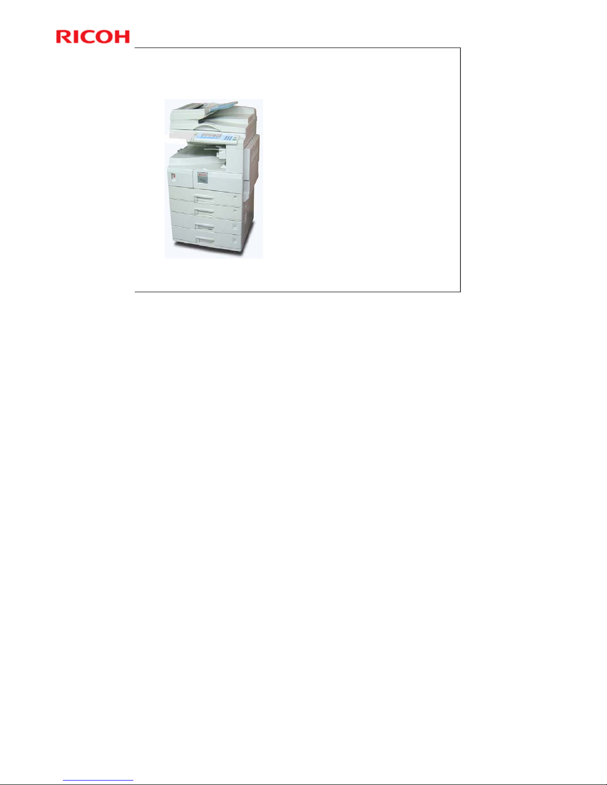
This is the machine you will
study in this training course.
Note the following:
Paper trays
Bypass tray
» On right side of machine
– See next slide
Operation panel
ADF/ARDF (optional)
No additional notes.
Page 6
Model K-C3.5L
6
R
i
c
o
h
C
o
.
L
t
d
.
h
t
t
p
:
/
/
w
w
w
.
r
i
c
o
h
.
c
o
m/
Slide 6
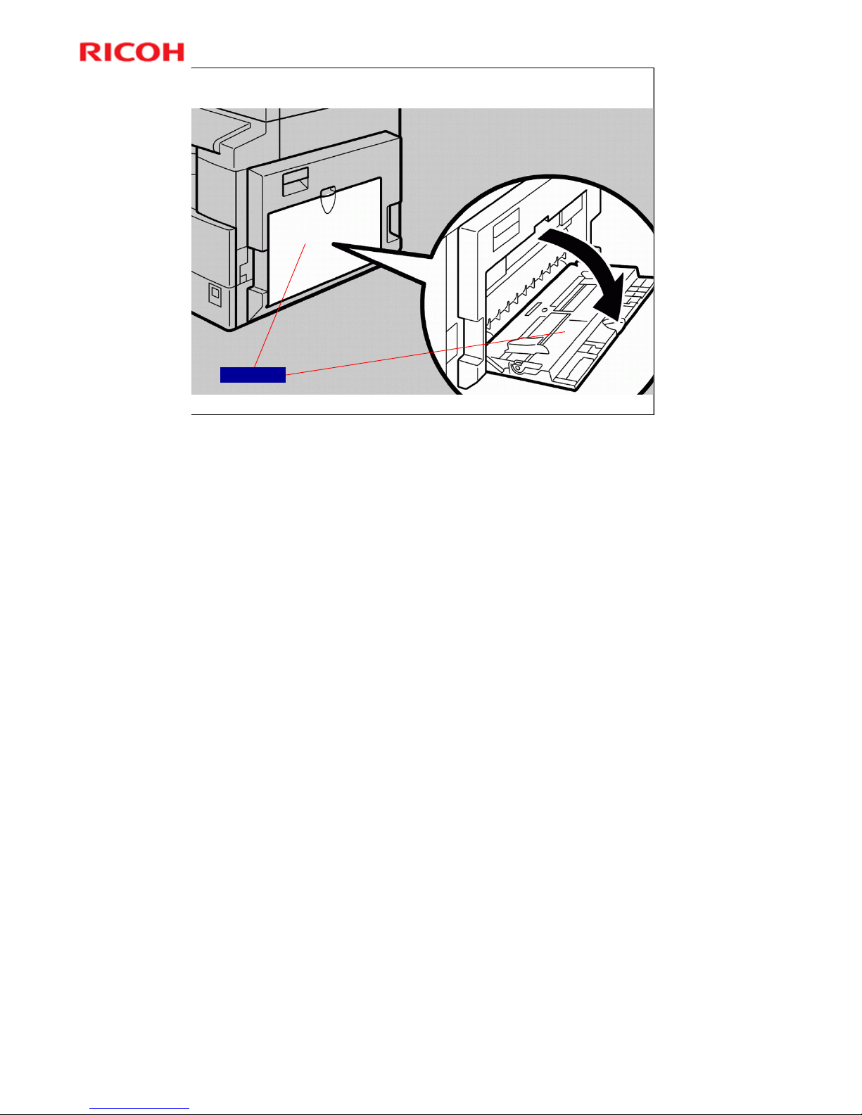
Bypass Tray
By-pass Tray
No additional notes.
Page 7
Model K-C3.5L
7
R
i
c
o
h
C
o
.
L
t
d
.
h
t
t
p
:
/
/
w
w
w
.
r
i
c
o
h
.
c
o
m/
Slide 7
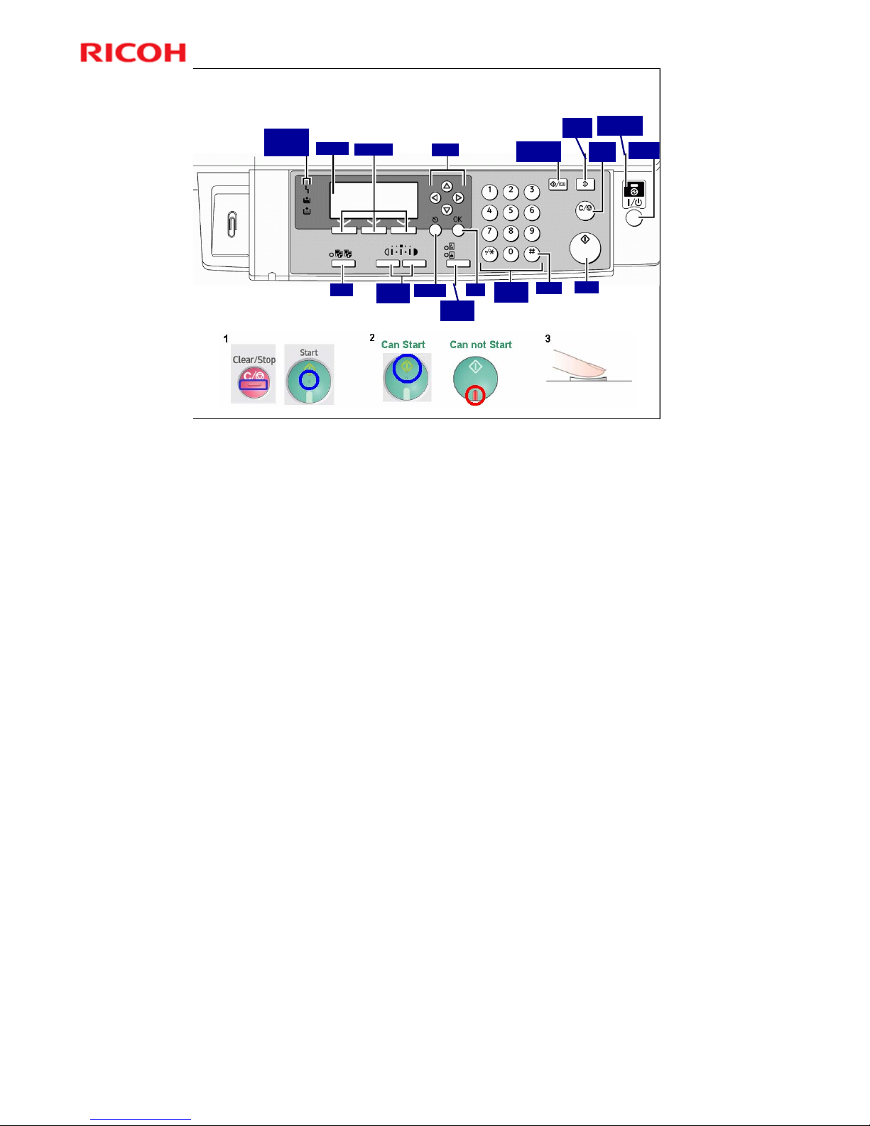
Operation Panel
Start
Error
Load Paper
Add Toner
Display
Selection
Scroll
Clear/
Stop
Main Power
Indicator
Operation
Switch
# key
Escape
Lighter/
Darker
Sort
Number
Keys
OK
Original
Type
Clear
Modes
User Tools/
Counter
No additional notes.
Page 8
Model K-C3.5L
8
R
i
c
o
h
C
o
.
L
t
d
.
h
t
t
p
:
/
/
w
w
w
.
r
i
c
o
h
.
c
o
m/
Slide 8
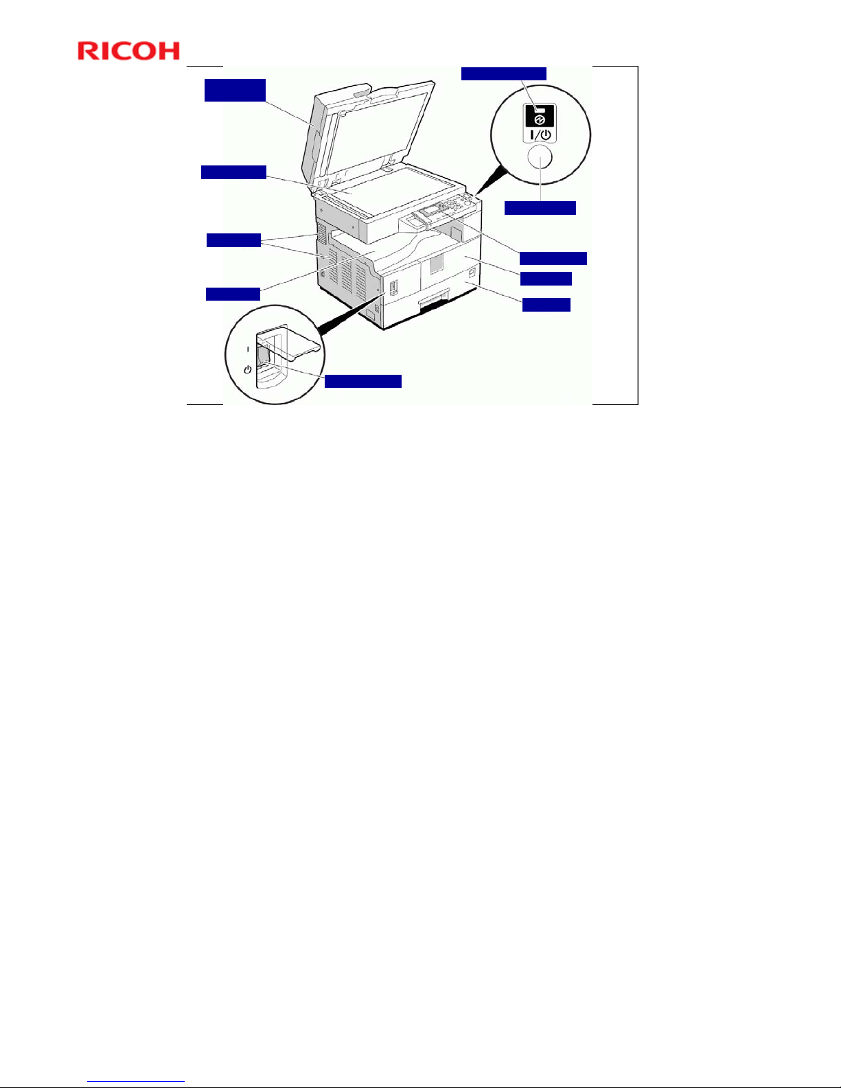
External
Part Names
Paper Tray
Front Cover
Operation Panel
Main Power Indicator
Main Power Switch
Internal Tray
Internal Tray
Exposure Glass
Platen Cover/
ADF (optional)
Operation Switch
"Operation Switch" refers to the Operation Panel Power Switch.
Page 9
Model K-C3.5L
9
R
i
c
o
h
C
o
.
L
t
d
.
h
t
t
p
:
/
/
w
w
w
.
r
i
c
o
h
.
c
o
m/
Slide 9
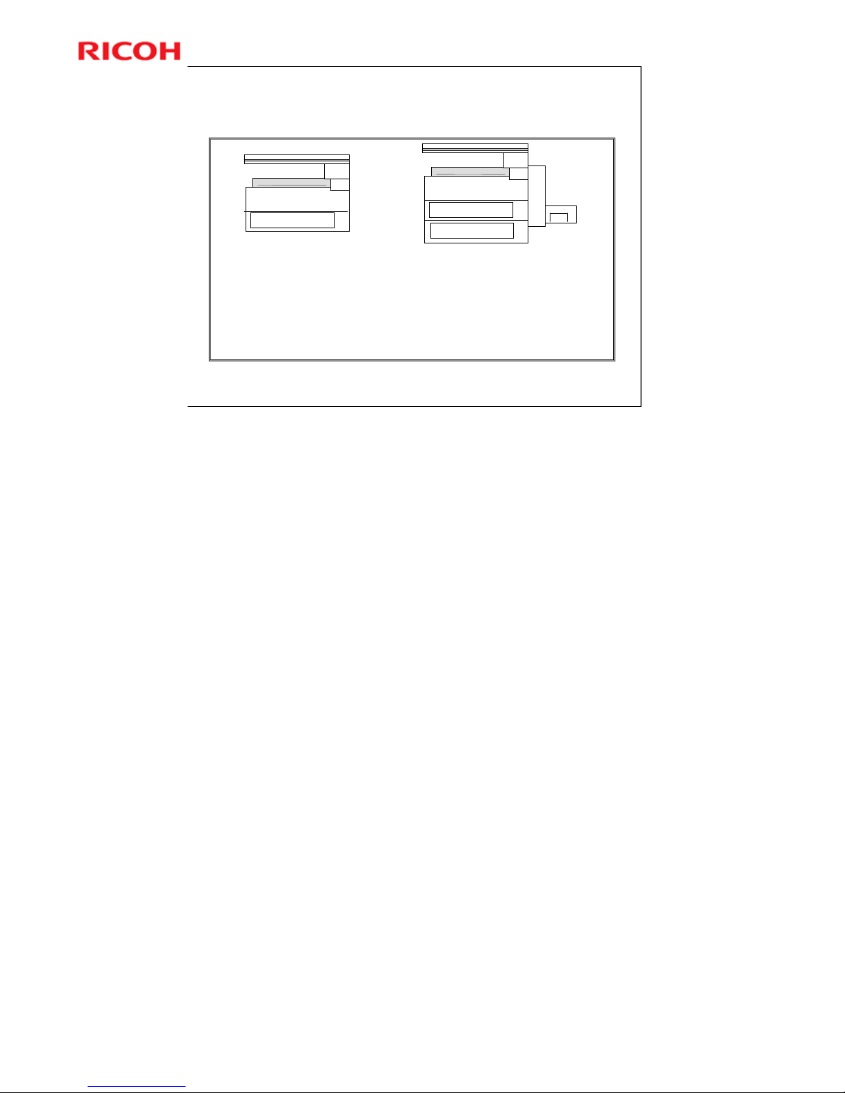
Standard Components
250
250
250
K-C3.5Lb Mainframe K-C3.5Lcd Mainframe
•Copy/Printer/Twain Scanner
•16MB Memory
•16MB+32MB memory (w/o NIC model)
•250-sheet x1 tray
•100-sheet bypass tray
•250-sheet output tray
•USB 2.0
•Copy/Printer/Twain Scanner
•Duplex
•16MB Memory
•16MB+32MB memory (w/o NIC model)
•250-sheet x2 tray
•100-sheet bypass tray
•250-sheet output tray
•USB 2.0
No additional notes.
Page 10

Model K-C3.5L
10
R
i
c
o
h
C
o
.
L
t
d
.
h
t
t
p
:
/
/
w
w
w
.
r
i
c
o
h
.
c
o
m/
Slide 10
The external optional
units are shown to the
right.
Internal option:
NIC (Network
interface card)
Optional Units
1. Platen Cover
2. ADF
3. ARDF: Only for K-C3Lcd
4. 1 Bin Tray: Only for K-C3Lcd
500
5. 1-tray paper bank
500
500
6. 2-tray paper bank
7. Accessibility handles for standard and
optional trays
No additional notes.
Page 11

Model K-C3.5L
11
R
i
c
o
h
C
o
.
L
t
d
.
h
t
t
p
:
/
/
w
w
w
.
r
i
c
o
h
.
c
o
m/
Slide 11
Model K-C3.5L
Service Training
2. Specifications
No additional notes.
Page 12

Model K-C3.5L
12
R
i
c
o
h
C
o
.
L
t
d
.
h
t
t
p
:
/
/
w
w
w
.
r
i
c
o
h
.
c
o
m/
Slide 12
General Specifications
Configuration
Desktop
Scanning system
Flatbed with CCD sensing elements
Printing process
Laser beam exposure
Dry, dual-component development system
Zoom
50% to 200% in 1% steps
Power Consumption
Full system
» Less than 1.28 kW
Reduced Electrical Consumption via Lower Power mode
» Less than 1 W.
See Energy Saver Modes for more details.
Print speed
K-C3.5Lb: 16 cpm (18 cpm for B268-50)
K-C3.5Lcd: 20 cpm
First copy time
Less than 6.5 seconds (A4/8½" x 11" LEF)
Warm-up
Less than 15 seconds
Refer to the field service manual for detailed specifications.
Page 13

Model K-C3.5L
13
R
i
c
o
h
C
o
.
L
t
d
.
h
t
t
p
:
/
/
w
w
w
.
r
i
c
o
h
.
c
o
m/
Slide 13
3. Installation
Model K-C3.5L
Service Training
No additional notes.
Page 14

Model K-C3.5L
14
R
i
c
o
h
C
o
.
L
t
d
.
h
t
t
p
:
/
/
w
w
w
.
r
i
c
o
h
.
c
o
m/
Slide 14
Install the Copier
Procedure: Copier Installation (see field service manual)
Developer Initialization must be performed via SP-2214-1
After installing machine & all options, and making all test
copies, record value of total counter.
» This is very important, because this value will be used for billing
with Meter Click contracts.
» Also, inform customer of value along with reason why counter
does not start from zero.
– Do not set to zero.
No additional notes.
Page 15
Model K-C3.5L
15
R
i
c
o
h
C
o
.
L
t
d
.
h
t
t
p
:
/
/
w
w
w
.
r
i
c
o
h
.
c
o
m/
Slide 15
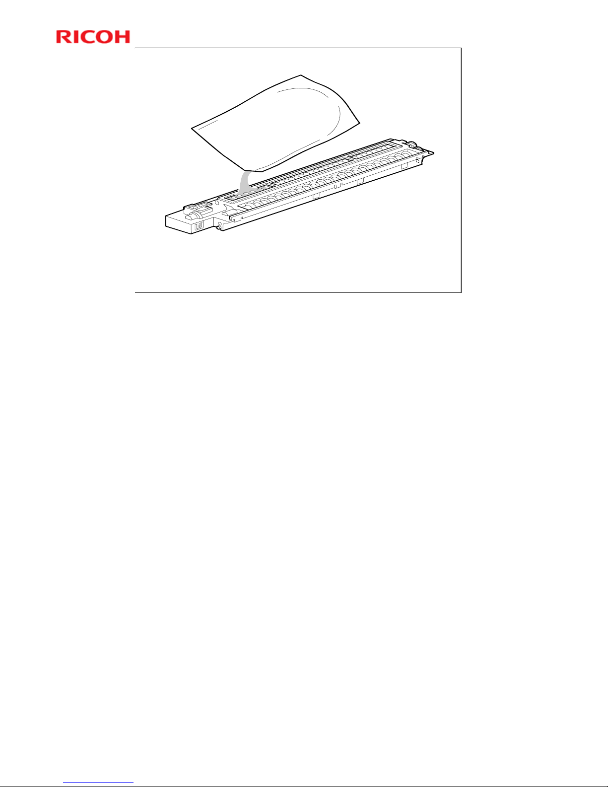
Putting in Developer
Make only a small cut in top corner of bag for better control when pouring.
Make sure not to spill developer on the gears.
If you have to turn the gears to distribute developer evenly, make sure to do so
very slowly and as little as possible. Otherwise developer may spill.
After pouring in developer, initialize it with SP-2214-1.
No additional notes.
Page 16

Model K-C3.5L
16
R
i
c
o
h
C
o
.
L
t
d
.
h
t
t
p
:
/
/
w
w
w
.
r
i
c
o
h
.
c
o
m/
Slide 16
Installation of Options
Install the following options. See the FSM for all procedures.
Platen Cover, ADF, or ARDF
» Only one of these can be installed.
Network Interface Board
» This NIB is new with this product.
Two-tray Paper Tray Unit
One-tray Paper Tray Unit
One-Bin Tray
Special Options (GW controller)
Install the following if required. These options have their own
separate service manuals.
Printer/Scanner Unit Type 2000
Fax Option Type 2000
No additional notes.
Page 17

Model K-C3.5L
17
R
i
c
o
h
C
o
.
L
t
d
.
h
t
t
p
:
/
/
w
w
w
.
r
i
c
o
h
.
c
o
m/
Slide 17
4. Machine Overview
Model K-C3.5L
Service Training
No additional notes.
Page 18
Model K-C3.5L
18
R
i
c
o
h
C
o
.
L
t
d
.
h
t
t
p
:
/
/
w
w
w
.
r
i
c
o
h
.
c
o
m/
Slide 18
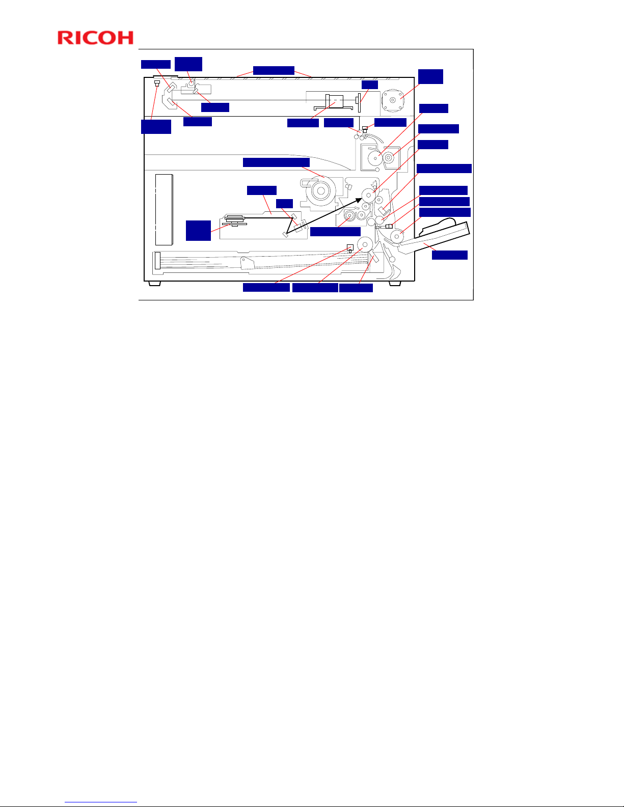
Mechanical Component Layout
2nd Mirror
Exposure
Lamp
1st Mirror
3rd Mirror
Exposure Glass
Lens Block
SBU
Scanner
HP Sensor
Scanner
Motor
Exit Sensor
Exit Roller
Hot Roller
Toner Supply Bottle Holder
OPC Drum
Image Density Sensor
Registration Sensor
By-pass Feed Roller
By-pass Tray
Laser Unit
Polygon
Mirror
Motor
WTL
Development Roller
Paper End Sensor
Paper Feed Roller
Friction Pad
Pressure Roller
Registration Roller
No additional notes.
Page 19
Model K-C3.5L
19
R
i
c
o
h
C
o
.
L
t
d
.
h
t
t
p
:
/
/
w
w
w
.
r
i
c
o
h
.
c
o
m/
Slide 19
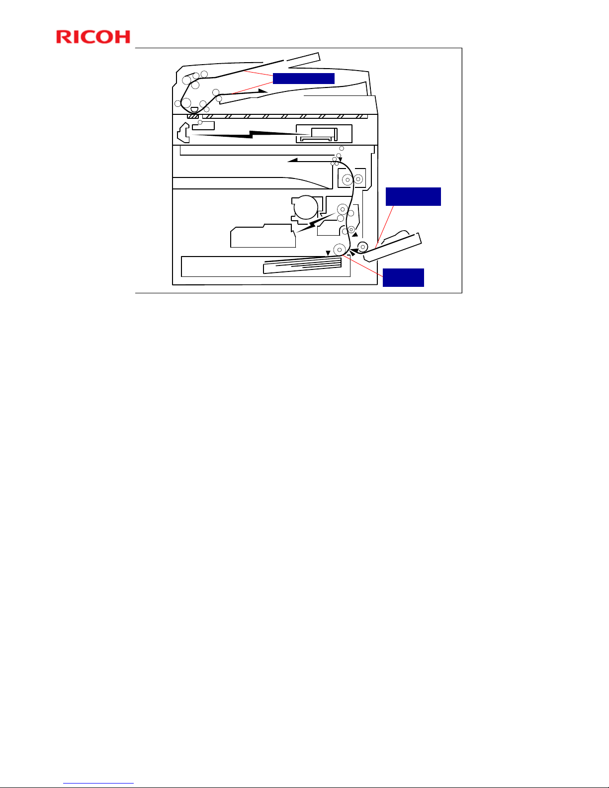
Paper Path
ADF Original Feed
Paper feed
from Tray 1
Paper feed from
By-pass Tray
No additional notes.
Page 20
Model K-C3.5L
20
R
i
c
o
h
C
o
.
L
t
d
.
h
t
t
p
:
/
/
w
w
w
.
r
i
c
o
h
.
c
o
m/
Slide 20
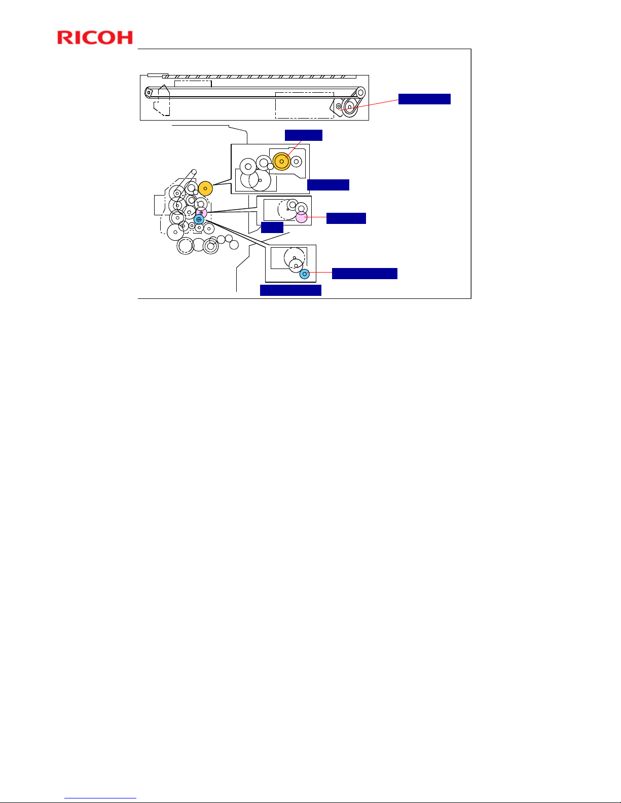
Main motor drives
fusing unit, PCU and
development unit.
PCU
Scanner Motor
Hot Roller
Development roller
OPC Drum
Drive Layout
Fusing Unit
Development Unit
More on Drive Layout
The top diagram shows the scanner. The scanner has one motor.
The bottom diagram shows how the main motor drives the fusing unit, PCU, and
development unit.
The three insets on the right hand side show the main motor and the gear trains
to these three units.
The main motor also drives the paper feed mechanisms via the train of gears in
the lower part of the bottom diagram.
Page 21
Model K-C3.5L
21
R
i
c
o
h
C
o
.
L
t
d
.
h
t
t
p
:
/
/
w
w
w
.
r
i
c
o
h
.
c
o
m/
Slide 21
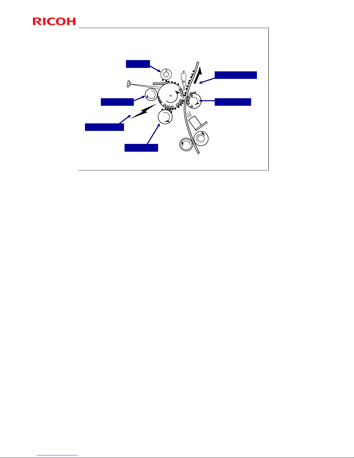
Copy Process
Development
Laser exposure
Drum charge
Cleaning
Image transfer
Paper separation
More on the Copy Process
The photoconductor unit (PCU) contains the drum, development roller, and
charge roller.
A charge roller gives the drum a negative charge.
The laser beam writes a latent image on the drum, switching on to discharge the
drum when writing black parts of the image. Toner is attracted to these
discharged parts of the drum.
The transfer roller applies a positive current to the reverse side of the paper (the
size of the current depends on the resolution and the paper size). T h is pulls the
toner off the drum and onto the paper.
The electrostatic pull from the transfer roller separates the paper from the drum.
There is also a discharge plate, which is grounded.
The quenching lamp removes residual charge from the drum.
The ID sensor and TD sensor are used for toner supply control.
Page 22

Model K-C3.5L
22
R
i
c
o
h
C
o
.
L
t
d
.
h
t
t
p
:
/
/
w
w
w
.
r
i
c
o
h
.
c
o
m/
Slide 22
5. Scanner
Model K-C3.5L
Service Training
No additional notes.
Page 23
Model K-C3.5L
23
R
i
c
o
h
C
o
.
L
t
d
.
h
t
t
p
:
/
/
w
w
w
.
r
i
c
o
h
.
c
o
m/
Slide 23
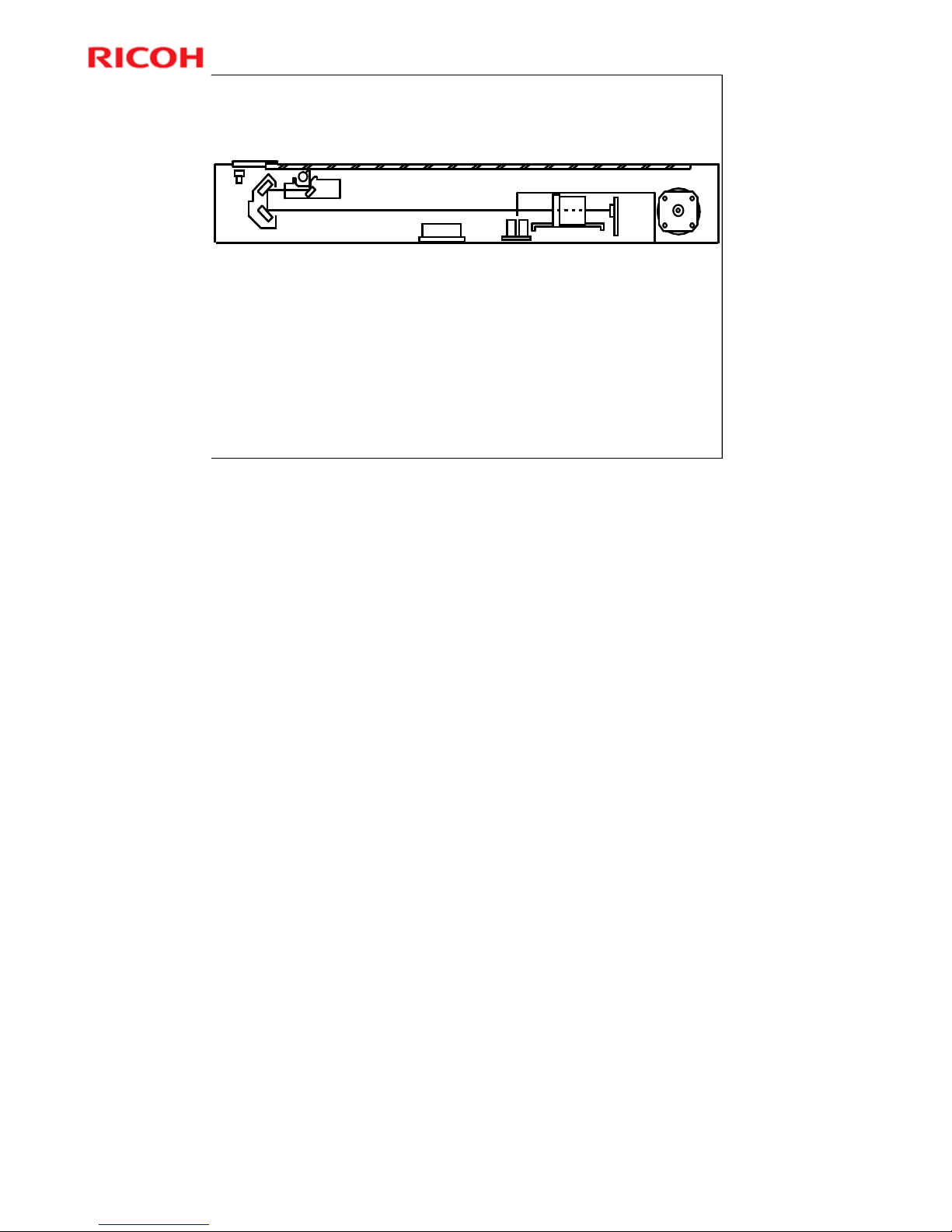
Scanner Unit
600 dpi CCD
Exposure lamp: One xenon lamp
The reflector reduces shadows on paste-up originals
No additional notes.
Page 24
Model K-C3.5L
24
R
i
c
o
h
C
o
.
L
t
d
.
h
t
t
p
:
/
/
w
w
w
.
r
i
c
o
h
.
c
o
m/
Slide 24
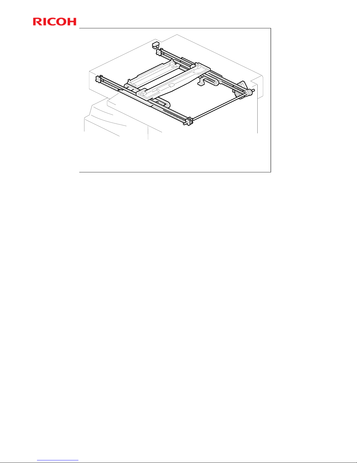
Scanner Drive
Scanner drive motor: Drives the scanner (100 mm/s)
Timing belts are used in this model
In ADF mode, scanner stays at home position.
Original is scanned while ADF feeds sheet through.
No additional notes.
Page 25
Model K-C3.5L
25
R
i
c
o
h
C
o
.
L
t
d
.
h
t
t
p
:
/
/
w
w
w
.
r
i
c
o
h
.
c
o
m/
Slide 25
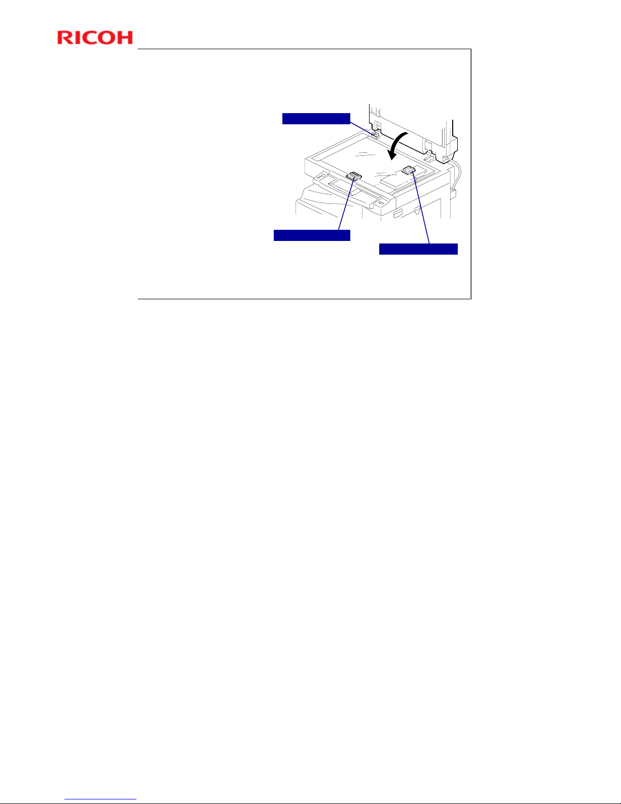
Original Size Detection – Platen Mode (1)
Reflective
photosensors
(APS sensors)
detect the paper
size.
Platen cover sensor
Original length sensors
Original width sensors
More on Original Size Detection in Platen Mode
Overview
Study the APS sensors. There are two length sensors and two width sensors.
When the platen cover is being closed, the CPU checks the sensors when the
platen cover is about 15 cm above the exposure glass (detected by the platen
cover sensor).
If the platen cover stays open during copying, the CPU checks the sensors when
the Start key is pressed.
Multi-copy mode
Note that the machine scans each page once, and stores it to memory.
Page 26
Model K-C3.5L
26
R
i
c
o
h
C
o
.
L
t
d
.
h
t
t
p
:
/
/
w
w
w
.
r
i
c
o
h
.
c
o
m/
Slide 26
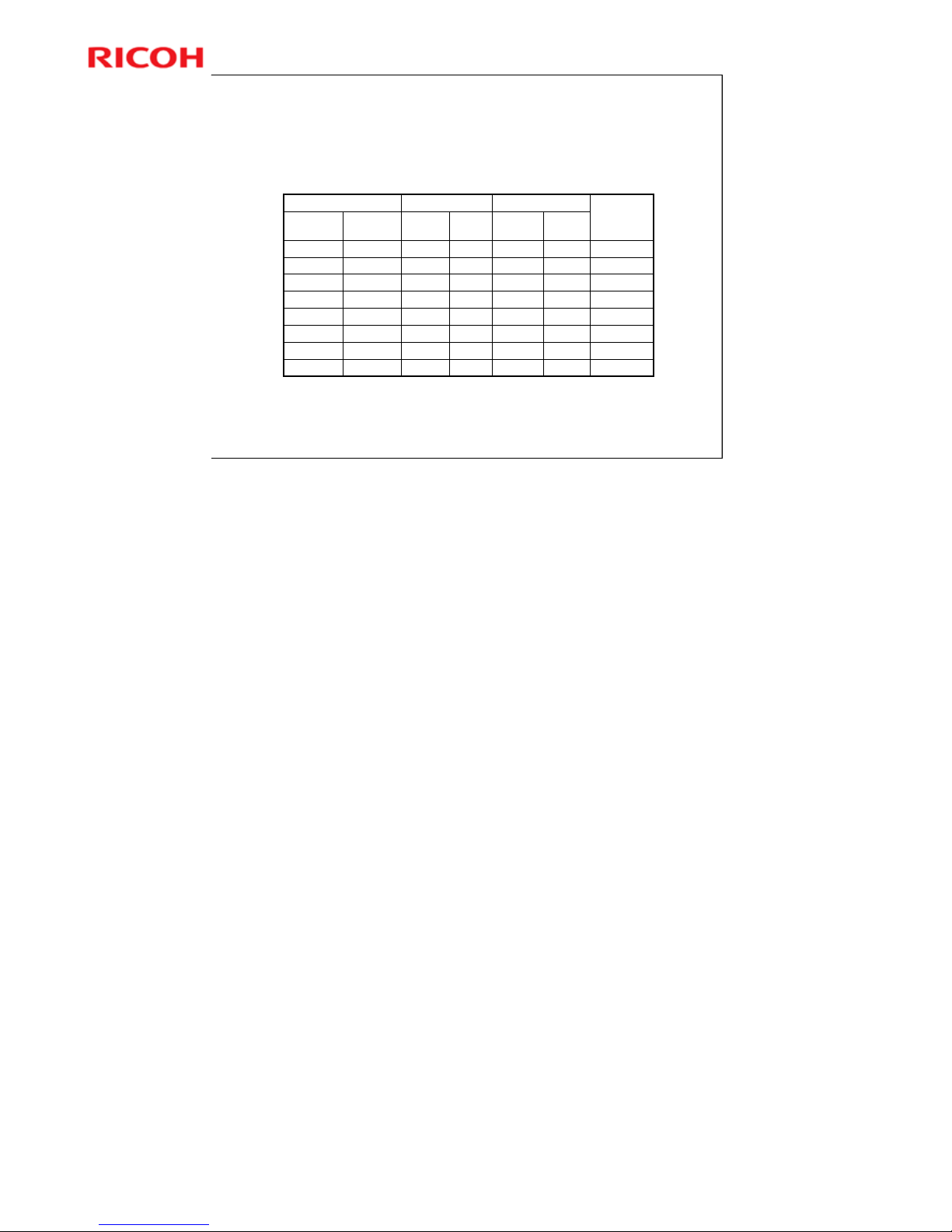
Original Size Detection – Platen Mode (2)
This table shows the outputs of the sensors for each original
size.
0101000010108.5"x13"–
0000000000008.5"x5.5"B5 SEF
0001000010008.5"x11"B5 LEF
00110000110011"x8.5"A4 LEF
0100000000108.5"x13"A4 SEF
110000000011–8.5"x13"
1101000010118.5"x11"B4
11110000111111"x17"A3
W1W2L1L2LT/DLT
Version
A3/A4
Version
SP4301
Display
Width SensorsLength SensorsOriginal Size
0: High (no paper), 1: Low (paper present)
The above table shows the outputs of the sensors for each original size. This original
size detection method eliminates the necessity for a pre-scan and increases the
machine's productivity.
For other combinations, “Cannot Detect Original Size” will be indicated on the operation
panel display (if SP 4303 is kept at the default setting). However, if the by-pass feeder is
used, note that the machine assumes that the copy paper is short-edge first. For
example, if A4 paper is placed long-edge first on the by-pass tray, the machine assumes
it is A3 paper and scans the full A3 area for the first copy of each page of the original,
disregarding the original size sensors. However, for each page, the data signal to the
laser diode is stopped to match the copy paper length detected by the registration
sensor. This means that copy time for the first page may be slower (because of the
longer time required for scanning), but it will be normal for the rest of the job.
Page 27

Model K-C3.5L
27
R
i
c
o
h
C
o
.
L
t
d
.
h
t
t
p
:
/
/
w
w
w
.
r
i
c
o
h
.
c
o
m/
Slide 27
SP Modes
SP 4008: Sub scan magnification
SP 4009: Main scan magnification
SP 4010: Leading edge registration
SP 4011: Side-to-side registration
SP 4013: Scanner free run (exposure lamp off)
SP 4305: Determines how machine interprets
original size sensors for A4/LT widths.
No additional notes.
Page 28

Model K-C3.5L
28
R
i
c
o
h
C
o
.
L
t
d
.
h
t
t
p
:
/
/
w
w
w
.
r
i
c
o
h
.
c
o
m/
Slide 28
Lab Work
Practice the following replacement and adjustment
procedures, referencing the FSM.
Scanner Unit
Copy adjustments
Do any of the procedures that you think are in need
of practicing.
Pay attention to all notes, cautions, and warnings in
the manual.
No additional notes.
Page 29

Model K-C3.5L
29
R
i
c
o
h
C
o
.
L
t
d
.
h
t
t
p
:
/
/
w
w
w
.
r
i
c
o
h
.
c
o
m/
Slide 29
6. Image Processing
Model K-C3.5L
Service Training
No additional notes.
Page 30
Model K-C3.5L
30
R
i
c
o
h
C
o
.
L
t
d
.
h
t
t
p
:
/
/
w
w
w
.
r
i
c
o
h
.
c
o
m/
Slide 30
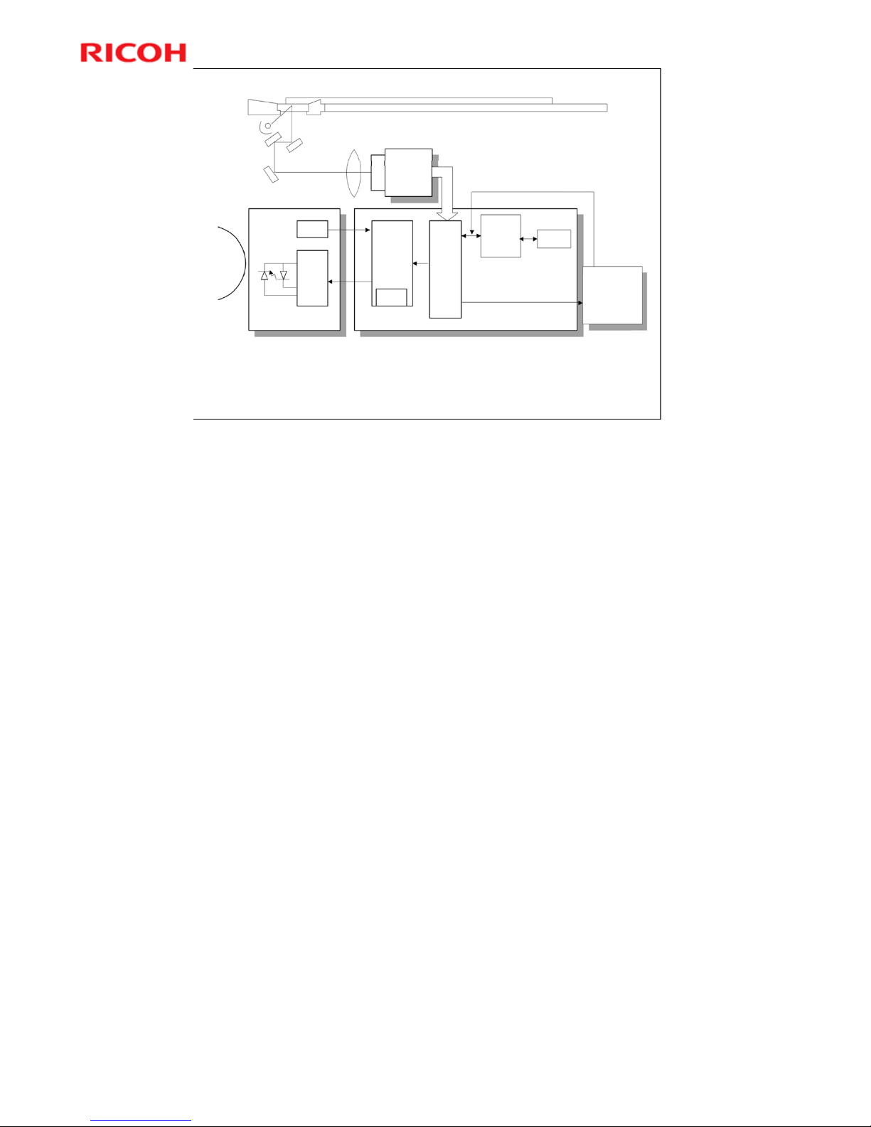
Image Processing Circuit
Data comes to the BICU board from three sources.
Scanner and SBU, Fax controller & Printer controller
See the notes section below for more details.
CCD
SBU
SCN
Drum
LSD
LD
Driver
LDD
VCU
FCI
IPU
BICU
PRN
DRAM
Memory
Control
IC
GDI and
GW
Controller
The CCD generates an analog video signal. The SBU (Sensor Board Unit) converts the
analog signal to an 8-bit digital signal, then it sends the digital signal to the BICU board.
The BICU board can be divided into three image-processing blocks: the IPU (Image
Processing Unit), FCI (Fine Character Image), and VCU (Video Control Unit).
IPU: Auto shading, filtering, magnification, scanner gamma correction, ID gamma
correction
VCU: Printer gamma correction, LD print timing control and laser power PWM control
FCI (inside the VCU): Smoothing
Note: The IPU and VCU are contained in the same IC called SCRATCH on the BICU.
Page 31
Model K-C3.5L
31
R
i
c
o
h
C
o
.
L
t
d
.
h
t
t
p
:
/
/
w
w
w
.
r
i
c
o
h
.
c
o
m/
Slide 31
SBU Board
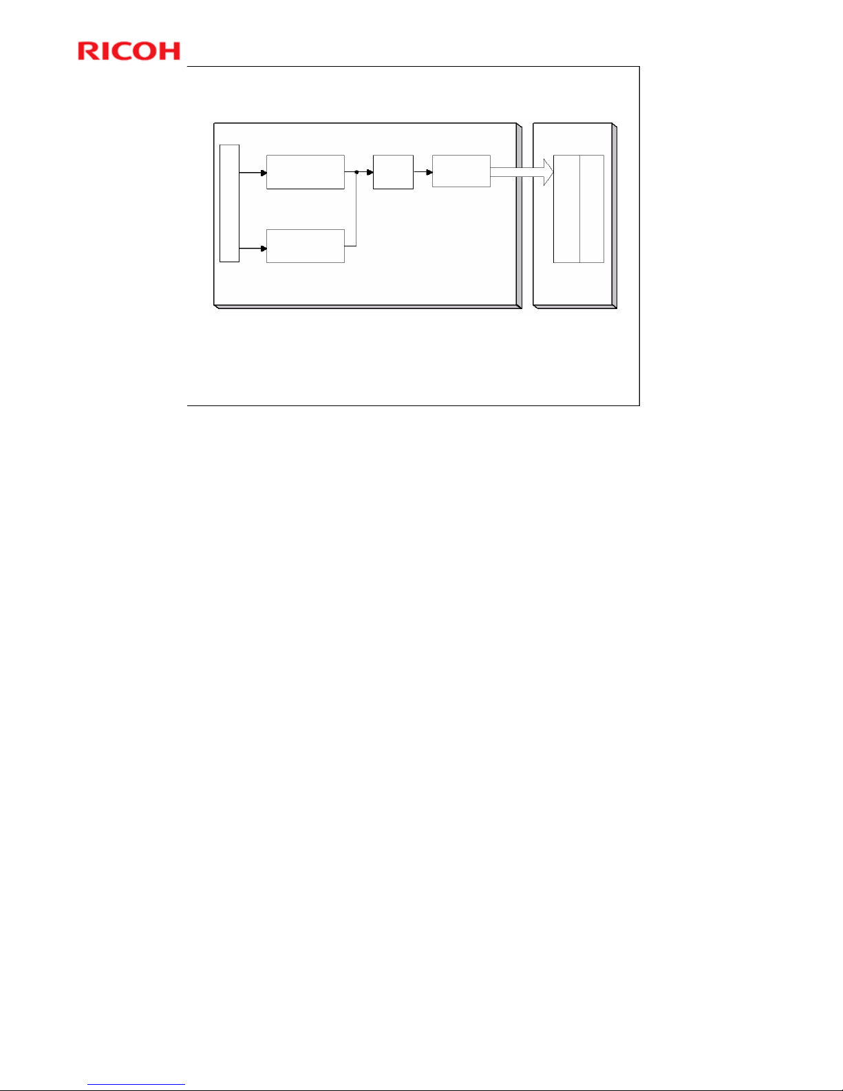
The CCD converts the light reflected from the original into an analog
signal.
Each CCD line has 7,400 pixels, producing a resolution of 600 dpi
(23.6 lines/mm).
CCD
SBU BICU
IPU VCU
8-bit Data
Digital
Processing
IC
A/D
Analog
Processing 1
Analog
Processing 2
O
E
The CCD converts the light reflected from the original into an analog signal. The CCD
line has 7,400 pixels and the resolution is 600 dpi (23.6 lines/mm).
The CCD has two output lines, for odd and even pixels, to the analog processing circuit.
The analog processing circuit performs the following operations on the signals from the
CCD:
1. Z/C (Zero Clamp): Adjusts the black level reference for even pixels to match the odd
pixels.
2. Signal Amplification: The analog signal is amplified by operational amplifiers.
After the above processing, the analog signals are converted to 8-bit signals by the A/D
converter. Each pixel will be assigned a value on a scale of 256 grades. Then, the
digitized image data goes to the BICU board.
Page 32
Model K-C3.5L
32
R
i
c
o
h
C
o
.
L
t
d
.
h
t
t
p
:
/
/
w
w
w
.
r
i
c
o
h
.
c
o
m/
Slide 32
Image Processing Unit
Memory
Controller
DRAM
FCILSD
LD
IPU
BICU
VCU
SBU
LDD
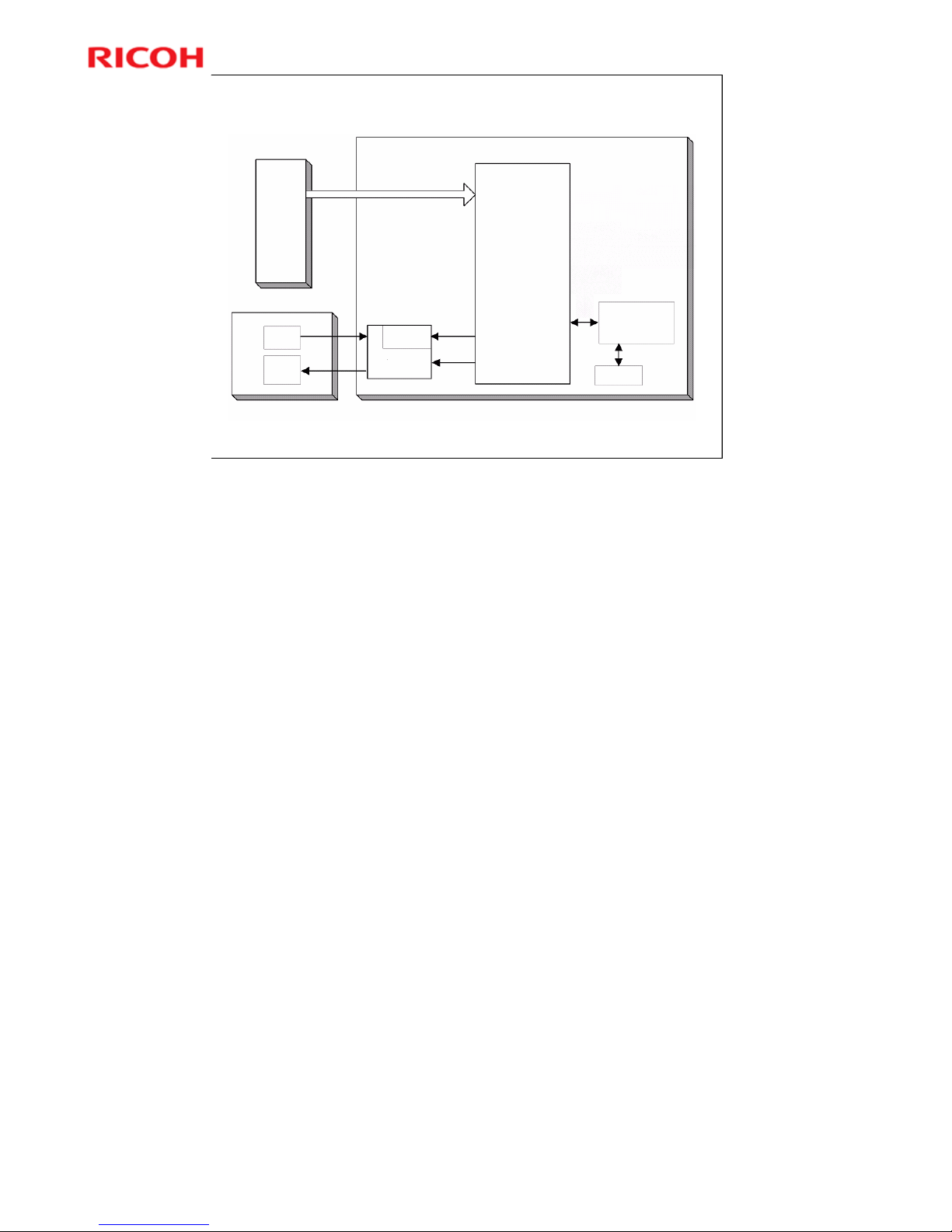
The image data from the SBU goes to the IPU (Image Processing Unit) on the BICU
board, which carries out the following processes on the image data:
1. Auto shading
2. White/black line correction
3. ADS
4. Scanner gamma correction
5. Magnification (main scan)
6. Filtering (MTF and smoothing)
7. ID gamma correction
8. Binary picture processing
9. Error diffusion
10. Dithering
11. Video path control
12. Test pattern generation
The image data then goes to the GDI controller.
Page 33

Model K-C3.5L
33
R
i
c
o
h
C
o
.
L
t
d
.
h
t
t
p
:
/
/
w
w
w
.
r
i
c
o
h
.
c
o
m/
Slide 33
Image Quality Adjustments - 1/3
Three basic original types
Text
Photo
Special (can only be accessed through a user tool)
Ten original types in total, selectable with a user
tool
Text modes: 2
Photo modes: 3
Special modes: 5
More on Image Quality Adjustments 1
There are three basic original types: text, photo, special.
Each of these types has sub-categories, as shown on the slide, to make a total
of 10 types that the user can select.
¾ Only two are immediately accessible at the operation panel. However, the
user can set up the operation panel with a user tool. This will be explained
on the next slide.
The table in the service manual gives details of the uses for each type.
In the SP tables and other parts of the manual, these modes are also referred to
as Text 1, Text 2, Photo 1, etc.
Text 2 (Sharp) does not use any greyscales for scanning.
Special 1 (Unneeded background) is similar to Text 2 (Sharp), but stronger.
Special 1 only works well in certain cases and was designed for a specific case
in the Japanese market (for copying vehicle inspection certificates).
Page 34

Model K-C3.5L
34
R
i
c
o
h
C
o
.
L
t
d
.
h
t
t
p
:
/
/
w
w
w
.
r
i
c
o
h
.
c
o
m/
Slide 34
Image Quality Adjustments - 2/3
The original mode key on the operation panel has
two settings:
Text
Photo
The default settings are:
Text indicator lit: Normal Text (Text 1)
Photo indicator lit: Photo Priority (Photo 1)
To allocate an original type:
Light either the Text or Photo indicator
Select the required original mode with User Tools -
Copier Features - Adjust Original Mode
More on Image Quality Adjustments 2
Only two of the 10 settings can be accessed directly from the operation panel.
In a new machine, these are Text 1 and Photo 1.
To change to a different two settings, use the user tool indicated on the slide.
Note that the Text indicator does not have to be allocated to a Text mode and
the Photo key does not have to be allocated to a Photo mode.
¾ For example, the Text indicator can be allocated to Photo 3, and the Photo
indicator can be allocated to Special 4.
Page 35

Model K-C3.5L
35
R
i
c
o
h
C
o
.
L
t
d
.
h
t
t
p
:
/
/
w
w
w
.
r
i
c
o
h
.
c
o
m/
Slide 35
Image Quality Adjustments - 3/3
SP 4922 to 4932: Image processing adjustments
SP 4921: Selects one of the original modes; only
one can be adjusted at any one time.
First select a mode with SP 4921. Then adjust it
with SP 4922 to 4932.
No additional notes.
Page 36

Model K-C3.5L
36
R
i
c
o
h
C
o
.
L
t
d
.
h
t
t
p
:
/
/
w
w
w
.
r
i
c
o
h
.
c
o
m/
Slide 36
SP Modes
SP 4015: Adjusts the area of the white plate used
for auto shading
SP 4903: ADS level
SP 4904: Lower limit for ADS
SP 4905: Determines how much of the image is
used for ADS (the whole width or just a narrow
strip)
Use SP 4015 to adjust the area of the white plate
that is used for auto-shading. Adjust this if there is
damage to the white plate causing defective auto
shading.
No additional notes.
Page 37

Model K-C3.5L
37
R
i
c
o
h
C
o
.
L
t
d
.
h
t
t
p
:
/
/
w
w
w
.
r
i
c
o
h
.
c
o
m/
Slide 37
Lab Work
Study the scanning adjustments in the FSM.
FSM Æ Replacement and Adjustment Æ Copy Adjustments
Printing/Scanning Æ Scanning
Do any of the procedures that you think that you
need to practice.
Pay attention to all notes, cautions, and warnings
in the manual.
If you have time, test the effects of the various
original modes and the SP modes used for
adjusting the image processing features.
No additional notes.
Page 38

Model K-C3.5L
38
R
i
c
o
h
C
o
.
L
t
d
.
h
t
t
p
:
/
/
w
w
w
.
r
i
c
o
h
.
c
o
m/
Slide 38
7. Laser Exposure
Model K-C3.5L
Service Training
No additional notes.
Page 39
Model K-C3.5L
39
R
i
c
o
h
C
o
.
L
t
d
.
h
t
t
p
:
/
/
w
w
w
.
r
i
c
o
h
.
c
o
m/
Slide 39
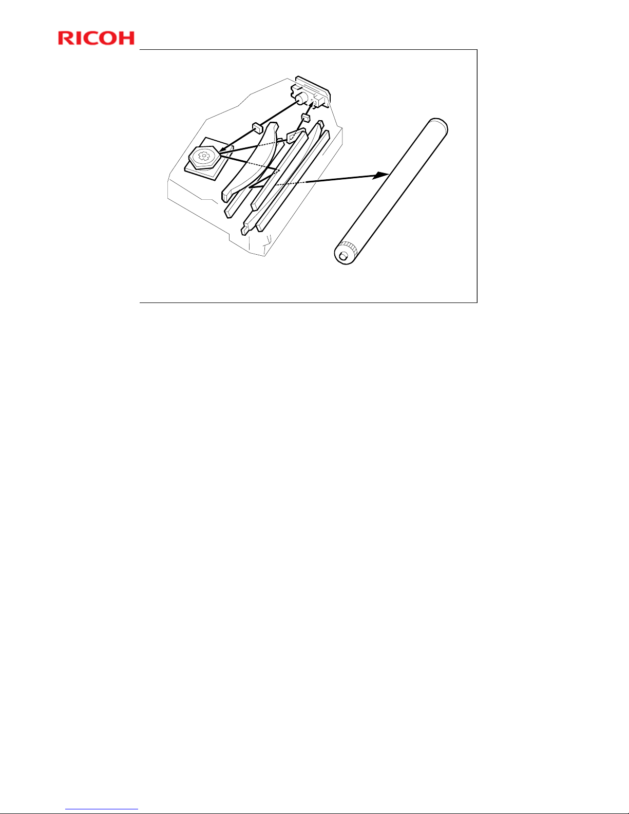
Laser Optics
One laser beam
There is only one laser beam in this model.
More on Laser Optics
The LSD (laser synchronisation detector) is part of the laser diode unit, and
cannot be replaced separately.
Laser beam
There is only one in this model.
Automatic Power Control
Laser power is controlled automatically.
Shutter
There is no mechanical shutter to stop the laser beam.
Safety Switches
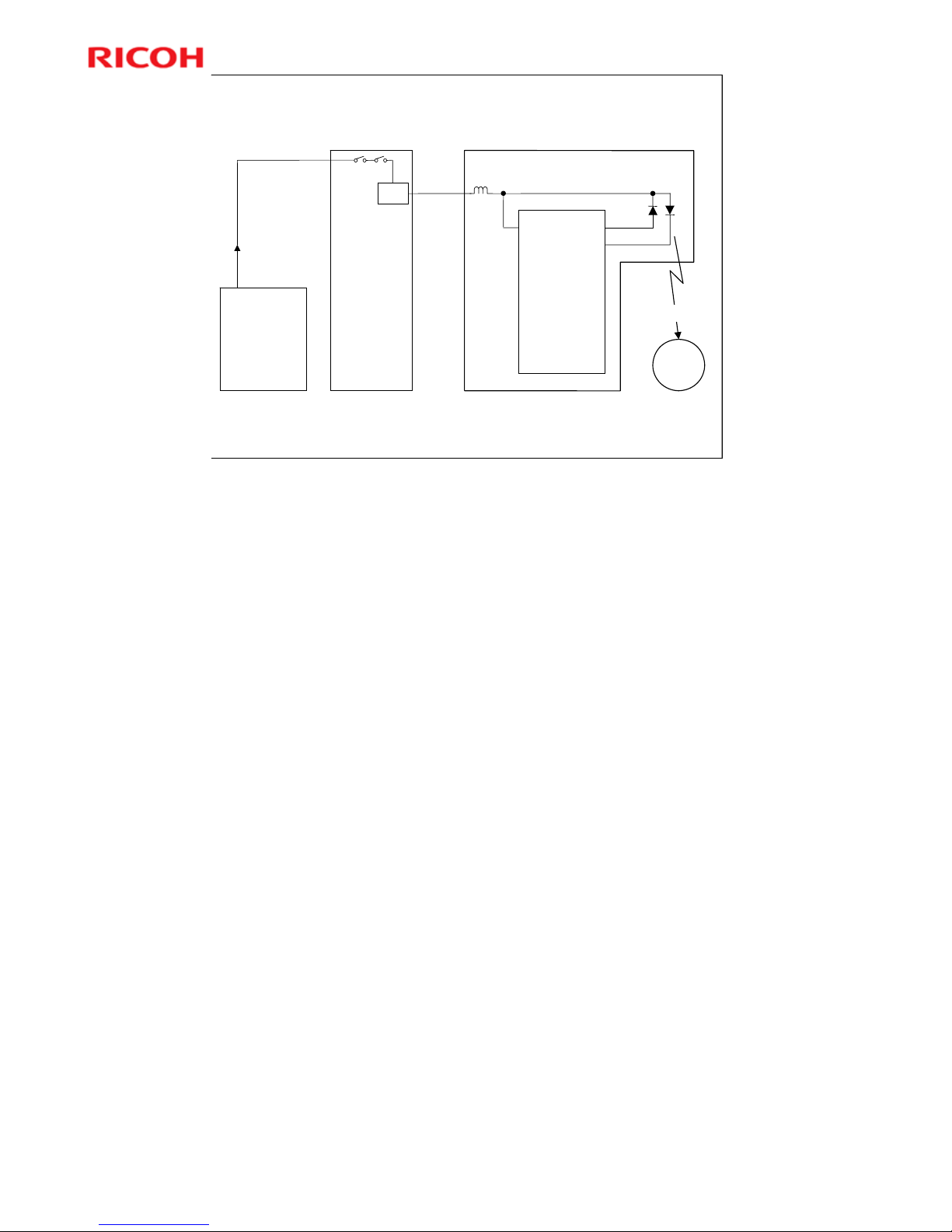
A safety switch stops power to the laser beam if the front or right cover is open.
Page 40
Model K-C3.5L
40
R
i
c
o
h
C
o
.
L
t
d
.
h
t
t
p
:
/
/
w
w
w
.
r
i
c
o
h
.
c
o
m/
Slide 40
When the front or right-side cover is open, a switch cuts power
to the laser diode.
Both covers operate the same switch.
LDD Drive Board
Front/Right Cover
Safety Switches
PSU
BICU
+5VLD
+24V
Optical Path
PD
LD
LD Driver IC
VCC
OPC
Drum
Laser
beam
REG
Safety Switches
No additional notes.
Page 41

Model K-C3.5L
41
R
i
c
o
h
C
o
.
L
t
d
.
h
t
t
p
:
/
/
w
w
w
.
r
i
c
o
h
.
c
o
m/
Slide 41
SP Modes
SP 2915: Polygon mirror idling time
SP 2998: Main scan magnification (printer)
There is also a main scan adjustment for the
scanner, which affects image processing
algorithms.
» SP 2998 affects laser on/off frequency in main scan
direction.
No additional notes.
Page 42

Model K-C3.5L
42
R
i
c
o
h
C
o
.
L
t
d
.
h
t
t
p
:
/
/
w
w
w
.
r
i
c
o
h
.
c
o
m/
Slide 42
Lab Work
Before you start
Go to the machine. Look for the front and right cover switches.
See how the covers operate the switches.
On the point-to-point diagram, look at the circuit from the power
supply through to the laser diode.
Practice the following
Laser unit component replacement procedures.
»FSM Æ Replacement and Adjustment Æ Laser Unit
Copy adjustments:
»FSM Æ Replacement and Adjustment Æ Copy Adjustments Printing/Scanning
Æ Printing
Do any procedures you think should be practiced.
IMPORTANT: Read the safety notice in the service manual, and
examine the warning labels. Pay attention to all notes, cautions,
and warnings in the manual.
No additional notes.
Page 43

Model K-C3.5L
43
R
i
c
o
h
C
o
.
L
t
d
.
h
t
t
p
:
/
/
w
w
w
.
r
i
c
o
h
.
c
o
m/
Slide 43
8. PCU (Photo Conductor Unit)
Model K-C3.5L
Service Training
No additional notes.
Page 44

Model K-C3.5L
44
R
i
c
o
h
C
o
.
L
t
d
.
h
t
t
p
:
/
/
w
w
w
.
r
i
c
o
h
.
c
o
m/
Slide 44
Overview
There is no new PCU detection in this machine. This
is due to the PCU not being a user-replaceable part.
Some of the PCU components are replaced
individually at PM.
When a new PCU is installed, new developer must
also be installed and SP 2214 must be done to
reinitialize the TD sensor.
No additional notes.
Page 45
Model K-C3.5L
45
R
i
c
o
h
C
o
.
L
t
d
.
h
t
t
p
:
/
/
w
w
w
.
r
i
c
o
h
.
c
o
m/
Slide 45
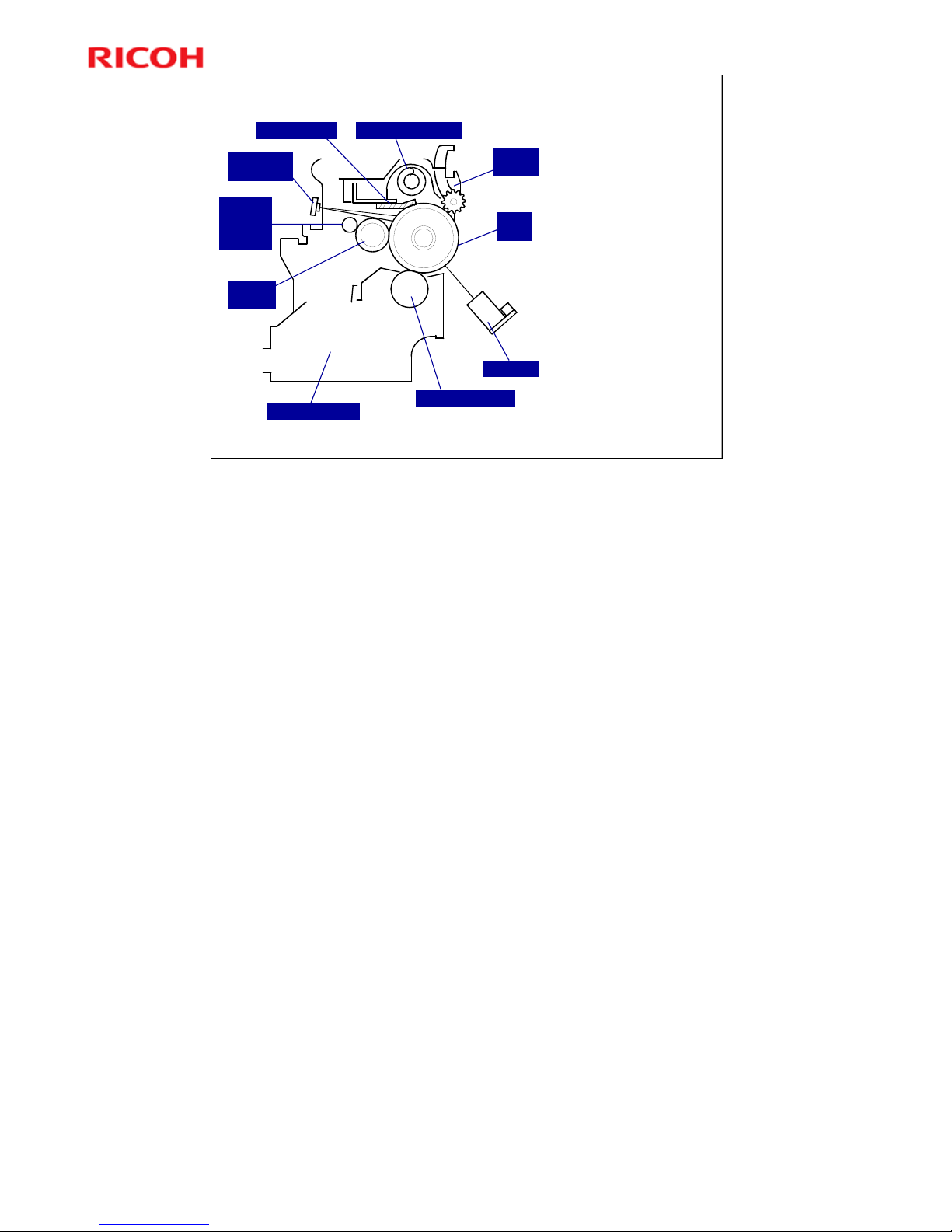
PCU Components
OPC Drum (30
mm diameter)
Charge Roller
With cleaning
brush
Pick-off Pawls
Cleaning Unit
Counter blade
mechanism
Edge cleaning
mechanism
Toner
recycling
Cleaning blade Toner collection coil
Pick-off
pawls
OPC
drum
ID sensor
Development roller
Development unit
Charge
roller
Charge
roller
cleaning
brush
Quenching
lamp
OPC = Organic Photo-Conductor
The ID sensor and quenching lamp are not included in the PCU.
Page 46

Model K-C3.5L
46
R
i
c
o
h
C
o
.
L
t
d
.
h
t
t
p
:
/
/
w
w
w
.
r
i
c
o
h
.
c
o
m/
Slide 46
PCU Details
The PCU contains the following.
OPC drum
Development unit (including development roller
and TD sensor)
Charge roller and charge roller cleaning brush
Drum cleaning unit (blade, toner collection coil)
Pick-off pawls
The PCU does not contain the following.
Transfer roller
ID sensor
Quenching lamp
Toner bottle
No additional notes.
Page 47
Model K-C3.5L
47
R
i
c
o
h
C
o
.
L
t
d
.
h
t
t
p
:
/
/
w
w
w
.
r
i
c
o
h
.
c
o
m/
Slide 47
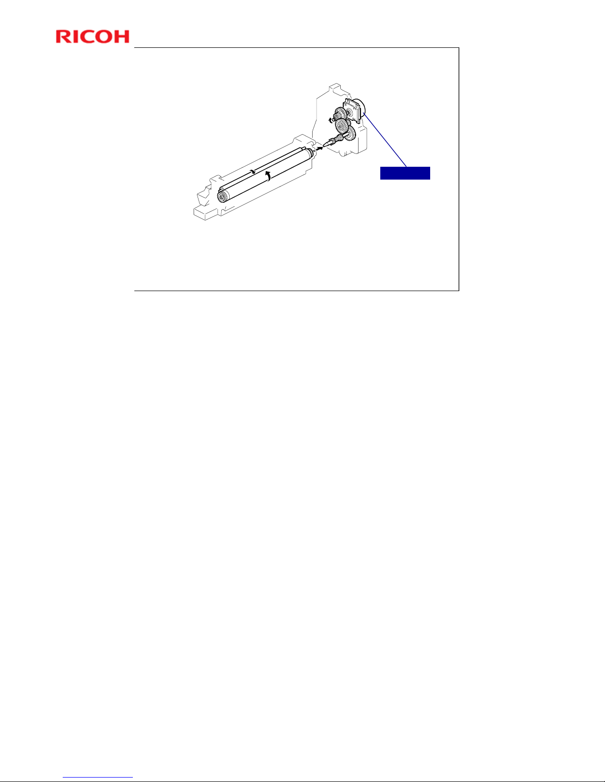
Drive
The main motor drives the drum through a
series of gears as shown above.
Main Motor
No additional notes.
Page 48

Model K-C3.5L
48
R
i
c
o
h
C
o
.
L
t
d
.
h
t
t
p
:
/
/
w
w
w
.
r
i
c
o
h
.
c
o
m/
Slide 48
Lab Work
Practice replacing PCU components.
FSM Æ Replacement and Adjustment Æ PCU Section
Be sure to do the After Replacement or Adjustment procedure
when you are finished practicing. (Also, see the notes section
below.)
Pay attention to all notes, cautions, and warnings in the
manual.
More on Lab Work
PCU
When a new PCU is installed, new developer must also be installed and SP
2214 must be done to reinitialize the TD sensor.
There is no new PCU detection in this machine. This is because the user does
not replace the PCU.
Developer
Before adding new developer, note that you must tap the top of the PCU at
several locations, as described in step 2 of the procedure.
¾ This is to remove recycled toner from the toner collection coil. If this toner is
not removed, it may fall into the new developer while the technician is
reassembling the machine. Then there will be too much toner in the
developer, and this will cause toner spots on copies.
¾ This toner may drop into the developer when replacing other parts of the
mechanism, but there is no point in tapping the coil because we are not
going to remove the old developer. So, to remove the excess toner, the
technician has to make skyshot copies after replacing any PCU
components, as explained in step 7 of the ‘After Replacement or
Adjustment’ section.
These skyshot copies are not necessary after replacing developer,
because the coil was tapped to remove the toner before adding new
developer.
Step 1 of the procedure says make 5 copies. These are test copies to
check whether we have a problem with excess toner causing spots on
copies.
Note that in step 6, we open and close the cover. This is to activate the cover
sensor and trigger the toner supply coil rotation to dislodge toner blockages in
the coil.
If new developer is added without changing the PCU, SP 2214 must also be
done.
¾ Also, after adding a new PCU, new developer must be added, so developer
Page 49

Model K-C3.5L
49
R
i
c
o
h
C
o
.
L
t
d
.
h
t
t
p
:
/
/
w
w
w
.
r
i
c
o
h
.
c
o
m/
Slide 49
9. Drum Charge
Model K-C3.5L
Service Training
No additional notes.
Page 50
Model K-C3.5L
50
R
i
c
o
h
C
o
.
L
t
d
.
h
t
t
p
:
/
/
w
w
w
.
r
i
c
o
h
.
c
o
m/
Slide 50
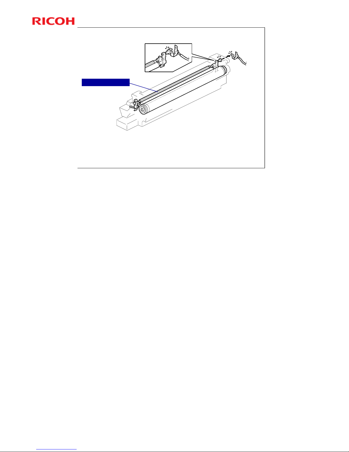
Drum Charge Roller
Roller is always in contact with drum.
Drum charge roller is at -1700 V for printing.
Drum surface voltage is - 950 V
Drum Charge Roller
More on Drum Charge Roller
The charge roller is part of the PCU unit.
The charge roller turns by friction with the drum.
A charge roller does not generate much ozone, so there is no ozone filter
Page 51
Model K-C3.5L
51
R
i
c
o
h
C
o
.
L
t
d
.
h
t
t
p
:
/
/
w
w
w
.
r
i
c
o
h
.
c
o
m/
Slide 51
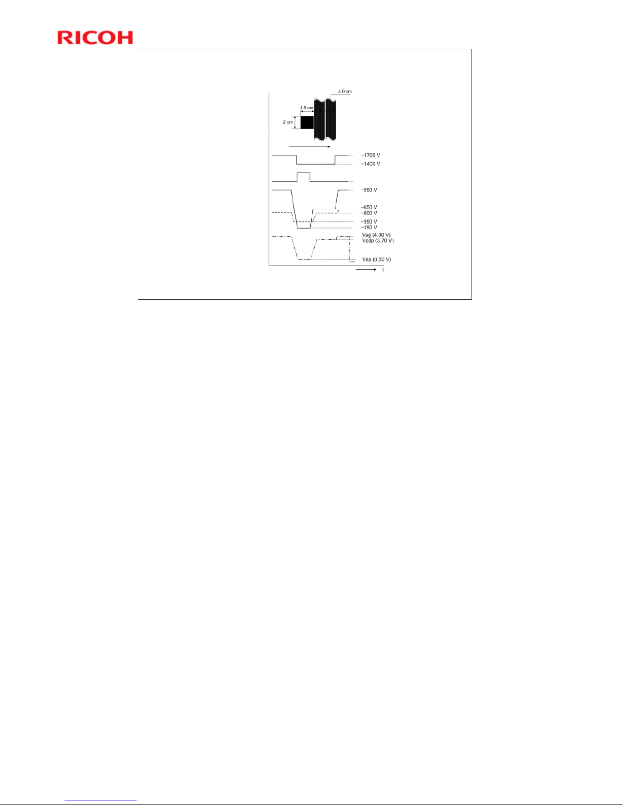
Charge Roller Voltage Correction
Details are in the notes section below.
ID Sensor Pattern
Charge Voltage
Laser Diode
Drum Potential
Development Bias
ID Sensor Output
On
Off
Sub-scan direction
With a drum charge roller system, the voltage transferred from roller to drum varies with
the temperature and humidity around the drum charge roller. The higher the temperature
or humidity is the higher the applied voltage required.
To compensate, the machine uses the ID sensor to measure the effects of current
environmental conditions. For this measurement, the process control parameters are
balanced so that any small change in drum potential caused by environmental effects is
reflected in a change in the amount of toner transferred to the drum.
This measurement is made immediately after the ID sensor pattern for toner density
control. Immediately after making ID sensor pattern [A], the charge roller voltage stays
the same, but the development bias goes up to –600 V; as a result the drum potential is
reduced to –650 V. The laser diode is not switched on, and the drum potential is now
slightly higher than the development bias, so a very small amount of toner transfers to
the drum. The ID sensor measures the density of this pattern [B], and the output voltage
is known as Vsdp. This voltage is compared with Vsg (read from the bare drum at the
same time).
If the humidity drops, the drum potential goes up (to a higher negative voltage) even if
the charge roller voltage supply stays the same (efficiency of voltage transfer is higher
with lower humidity). As a result, less toner is transferred to ID sensor pattern [B]. If the
sensor output reaches a certain point, the drum charge voltage will be reduced.
To determine whether to change the drum charge roller voltage, the machine compares
Vsdp with Vsg.
• Vsdp/Vsg > 0.95 = Make the drum charge voltage less negative (smaller) by 50 V
• Vsdp/Vsg < 0.90 = Make the drum charge voltage more negative (larger) by 50 V
Page 52

Model K-C3.5L
52
R
i
c
o
h
C
o
.
L
t
d
.
h
t
t
p
:
/
/
w
w
w
.
r
i
c
o
h
.
c
o
m/
Slide 52
ID Sensor Pattern Production Timing
The ID sensor pattern is made at the following
times:
During warm-up at power on
When the machine starts warming up from energy saver
mode and the temperature is less than the ta rget
temperature as set with SP Mode.
When the machine starts warming up from energy saver
mode and the machine prints more than 100 print s.
While machine is recovering from energy saver
mode, or while machine starts, BICU ignores IDsensor signals if fusing temperature is at
specified value or higher.
» Adjustable from 30 degrees to 90 via SP 2994)
No additional notes.
Page 53
Model K-C3.5L
53
R
i
c
o
h
C
o
.
L
t
d
.
h
t
t
p
:
/
/
w
w
w
.
r
i
c
o
h
.
c
o
m/
Slide 53
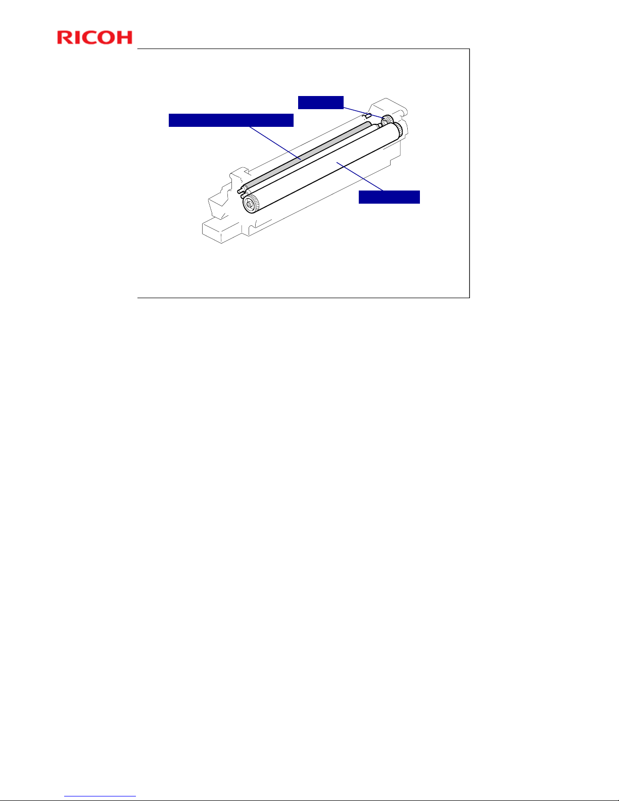
Charge Roller Cleaning
Cleaning Brush is always in contact with drum charge roller
A cam gear moves the charge roller from side to side to improve cleaning.
This waste toner is not recycled.
Charge Roller
Cam Gear
Charge Roller Cleaning Brush
No additional notes.
Page 54

Model K-C3.5L
54
R
i
c
o
h
C
o
.
L
t
d
.
h
t
t
p
:
/
/
w
w
w
.
r
i
c
o
h
.
c
o
m/
Slide 54
SP Modes
SP 2001: Charge roller voltage adjustment (for
printing and for making an ID sensor pattern).
No additional notes.
Page 55

Model K-C3.5L
55
R
i
c
o
h
C
o
.
L
t
d
.
h
t
t
p
:
/
/
w
w
w
.
r
i
c
o
h
.
c
o
m/
Slide 55
10. Development and Toner Supply
Model K-C3.5L
Service Training
No additional notes.
Page 56
Model K-C3.5L
56
R
i
c
o
h
C
o
.
L
t
d
.
h
t
t
p
:
/
/
w
w
w
.
r
i
c
o
h
.
c
o
m/
Slide 56
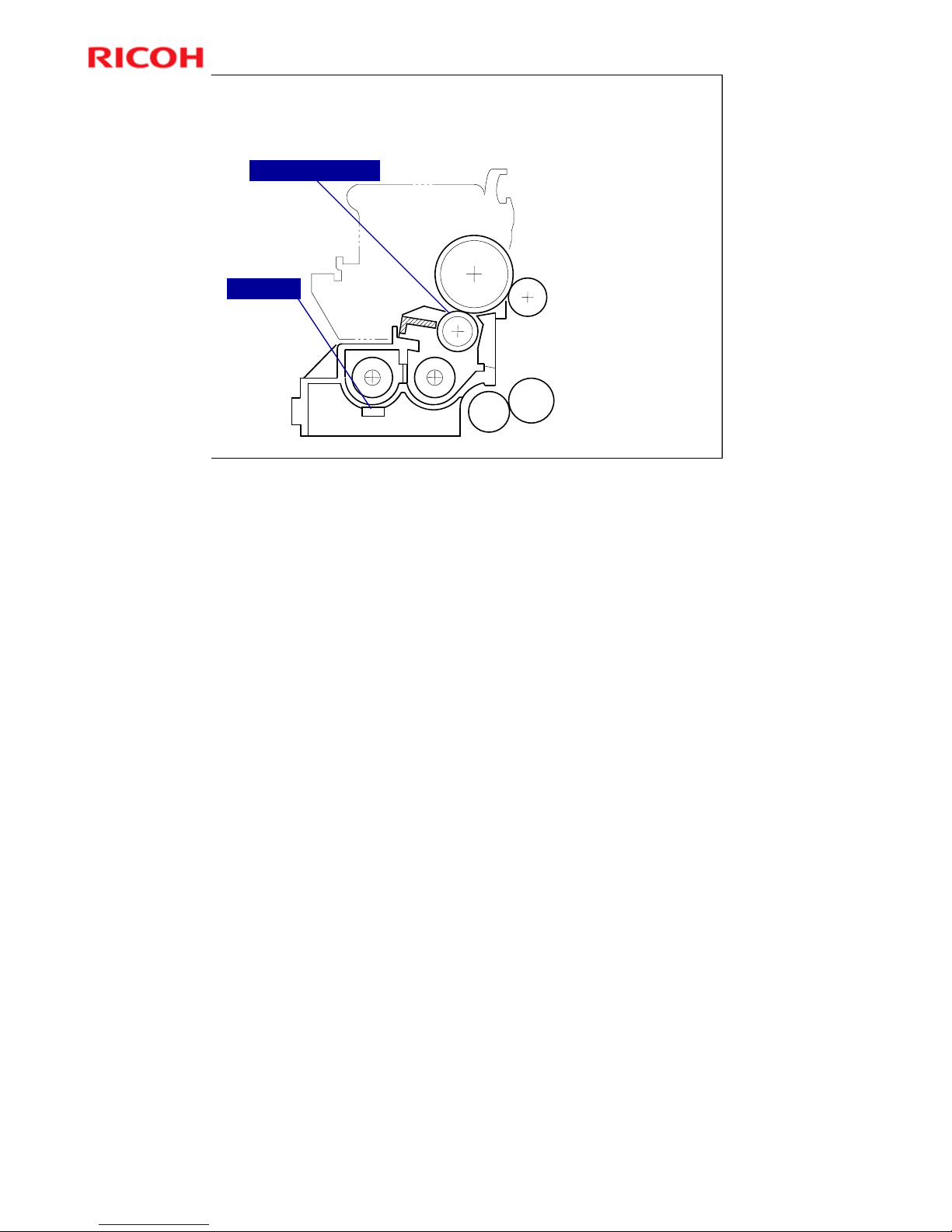
Overview
Single development
roller
Two mixing augers
Toner density control
TD sensor
ID sensor
Development Roller
TD Sensor
This machine uses a single-roller development system. Two mixing augers mix the
developer. The toner density (TD) sensor and image density (ID) sensor (see the
illustration in the PCU section) are used to control the image density.
Page 57
Model K-C3.5L
57
R
i
c
o
h
C
o
.
L
t
d
.
h
t
t
p
:
/
/
w
w
w
.
r
i
c
o
h
.
c
o
m/
Slide 57
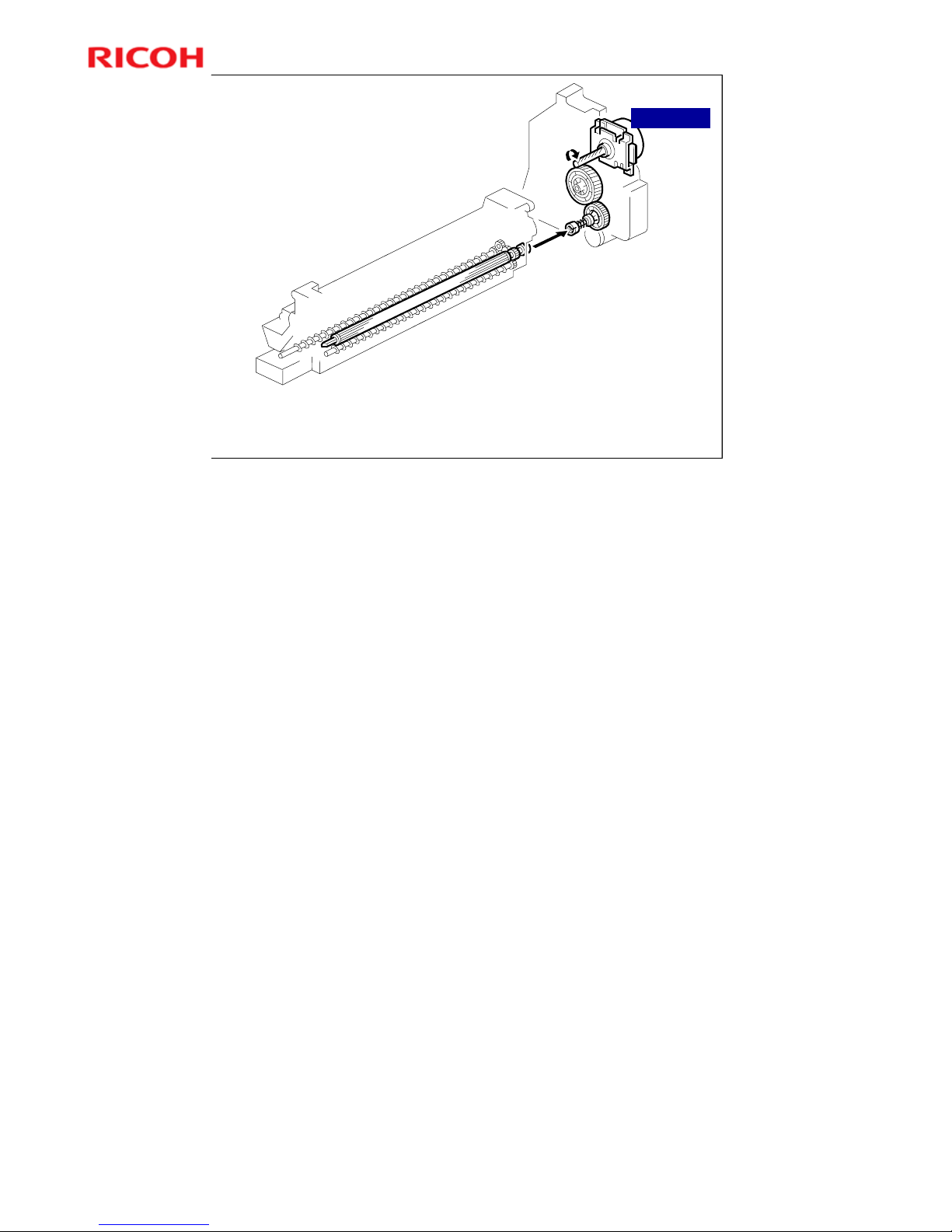
Drive
Main motor: Drives development mechanism, via development drive shaft.
Development drive shaft: Engages when PCU is pushed in.
Development roller turns whenever main motor is on.
No development clutch.
Main motor
No additional notes.
Page 58
Model K-C3.5L
58
R
i
c
o
h
C
o
.
L
t
d
.
h
t
t
p
:
/
/
w
w
w
.
r
i
c
o
h
.
c
o
m/
Slide 58
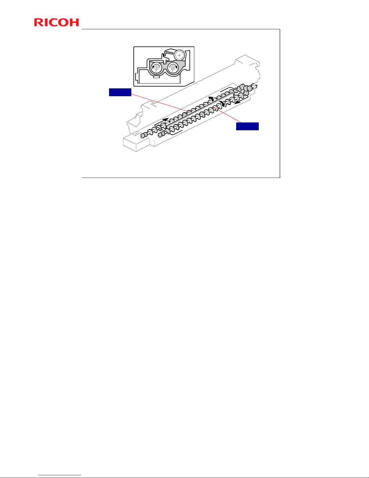
Developer Mixing
Two mixing augers keep developer mixed.
Auger 2 moves excess toner from development roller towards front.
Auger 1 moves this excess toner, mixed with new toner, to rear and back to development
roller.
Auger 1
Auger 2
More on Developer Mixing
Mixing does the following:
¾ Keeps the toner and developer evenly mixed
¾ Prevents lumps from forming
¾ Helps create a triboelectric charge on the toner.
The doctor blade splits the developer into the following two parts.
¾ One part goes to the development roller to form the magnetic brush and the
latent image on the drum.
¾ The other part is returned to the development unit, where it is mixed with
new developer (and recycled toner) and moved back to the development
roller.
Page 59
Model K-C3.5L
59
R
i
c
o
h
C
o
.
L
t
d
.
h
t
t
p
:
/
/
w
w
w
.
r
i
c
o
h
.
c
o
m/
Slide 59
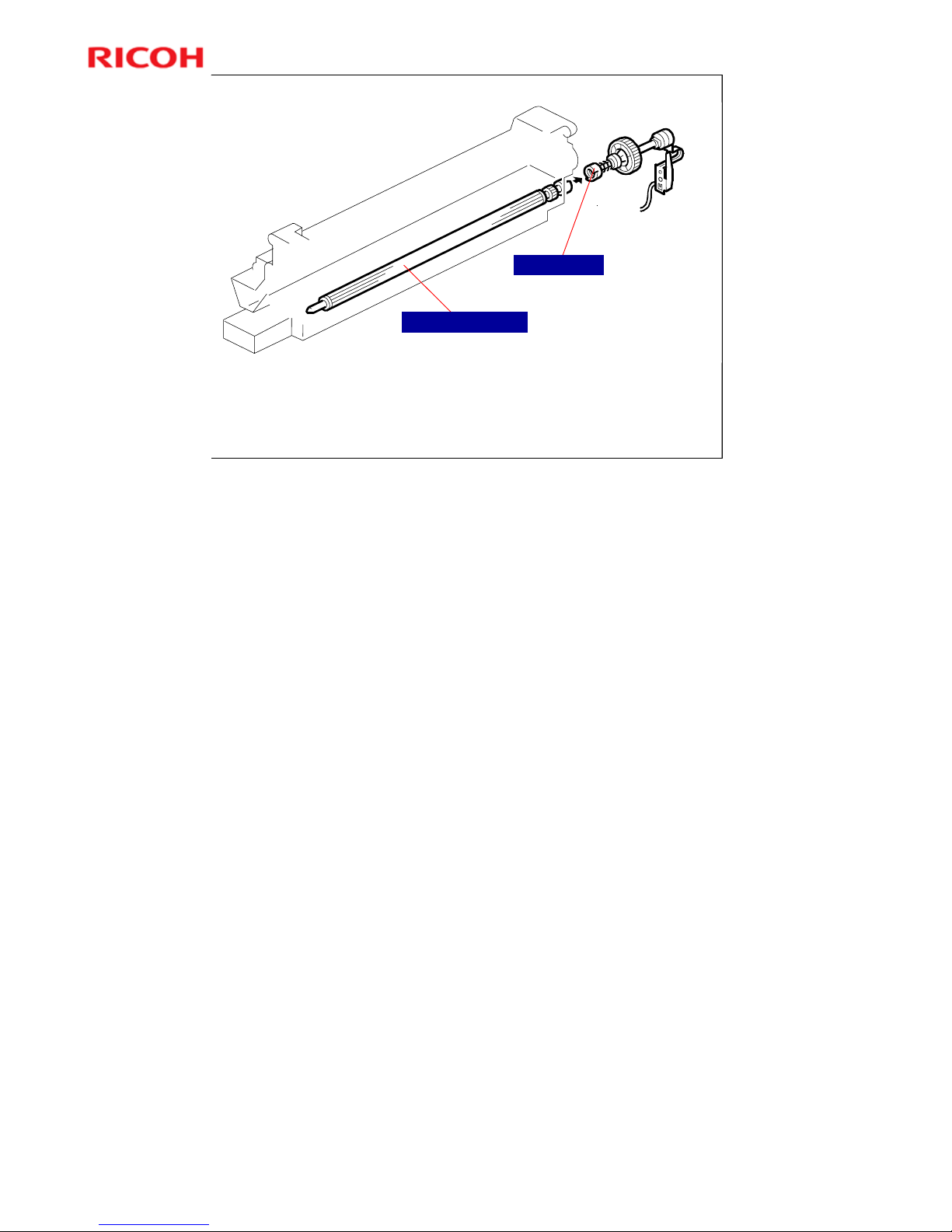
Development Bias
White areas: High negative charge (-950V)
Black areas: Discharged by the laser (about -150V)
Development bias (-650V): Forces the negatively-charged toner onto the
discharged areas of the drum.
Applied to development roller shaft through drive shaft.
Bias terminal
Development roller
More on Development Bias
This machine uses a negative-positive development system, in which black
areas of the latent image are at a low negative charge (about –154 ± 50 V) and
white areas are at a high negative charge (about –950 V).
To attract negatively charged toner to the black areas of the latent image on the
drum, the high voltage supply board applies a bias of –650 volts to the
development rollers throughout the image development process. The bias is
applied to the development roller shaft [A] through the drive shaft [B].
The development bias voltage (–650 V) can be adjusted with SP 2201 1.
Page 60
Model K-C3.5L
60
R
i
c
o
h
C
o
.
L
t
d
.
h
t
t
p
:
/
/
w
w
w
.
r
i
c
o
h
.
c
o
m/
Slide 60
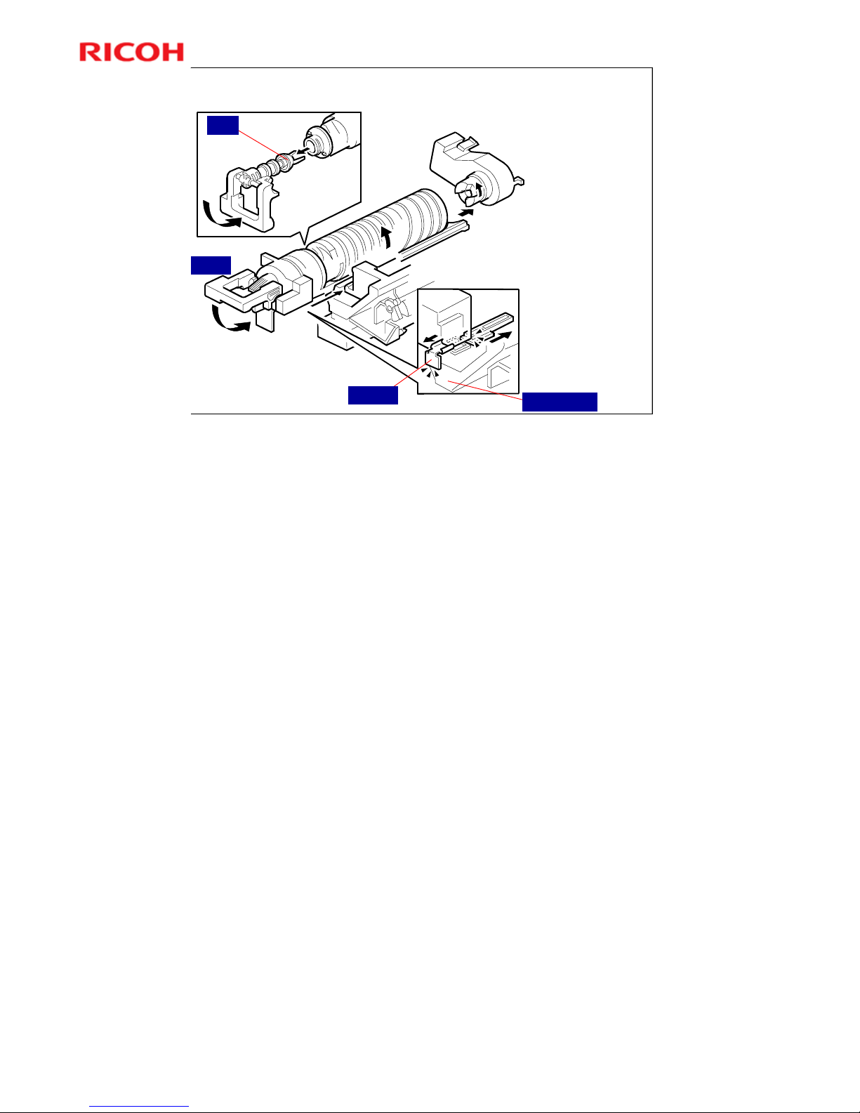
Toner Bottle Replenishment
Lever
When bottle is
placed in bottle
holder:
Shutter moves
against side of
PCU, and it
opens.
When lever is
returned
Cap is pulled
away so that
toner can come
out.
Cap
Shutter
Side of PCU
More on Toner Bottle Replenishment
When the bottle is placed in the machine, the shutter opens to allow toner to go
into the development unit.
¾ The shutter mechanism is shown in the bottom right part of the diagram.
Then, when the holder is released, the top of the bottle is pulled out.
¾ The holder mechanism is shown in the top left part of the diagram.
Page 61
Model K-C3.5L
61
R
i
c
o
h
C
o
.
L
t
d
.
h
t
t
p
:
/
/
w
w
w
.
r
i
c
o
h
.
c
o
m/
Slide 61
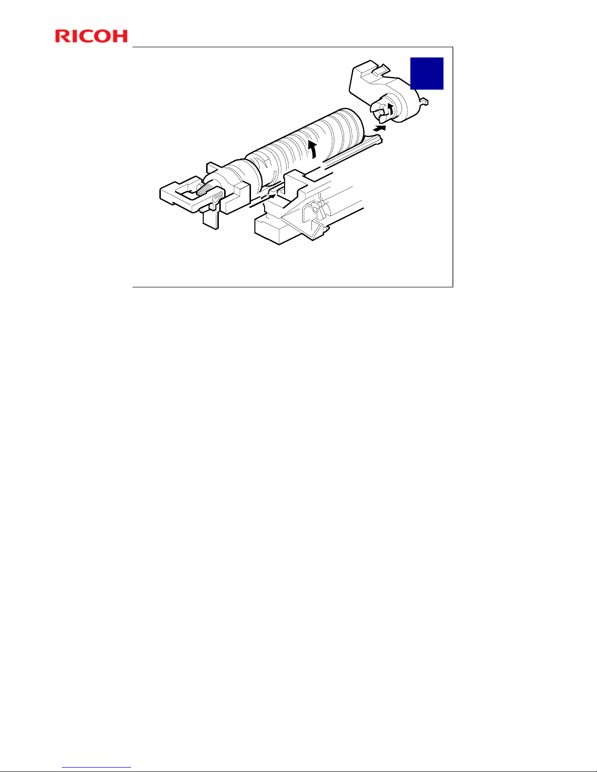
Toner
Supply
Motor
Toner supply motor turns the bottle
To supply fresh toner to development unit, toner supply motor turns on.
Spiral grooves help toner to move towards bottle exit.
Toner Supply - Bottle Drive
No additional notes.
Page 62
Model K-C3.5L
62
R
i
c
o
h
C
o
.
L
t
d
.
h
t
t
p
:
/
/
w
w
w
.
r
i
c
o
h
.
c
o
m/
Slide 62
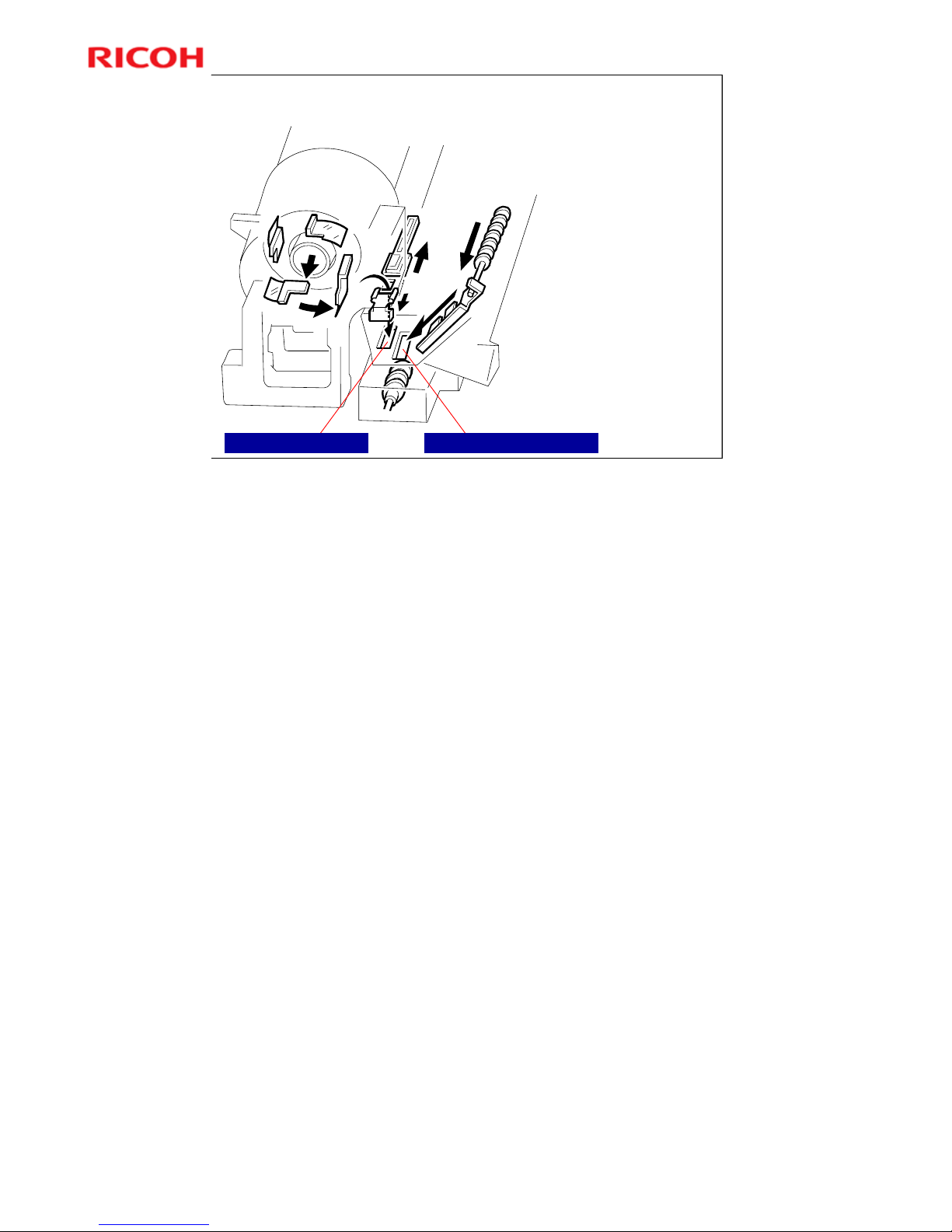
Toner Supply - Input to Development Unit
Mylar tabs in bottle
unit push toner
towards development
unit entrance.
Recycled toner from
drum also arrives at
this entrance.
Recycled toner enters hereNew toner enters here
More on Toner Supply Input to the Development Unit
Toner enters the development unit through the shutter.
¾ This shutter is opened when a bottle is put in the machine, as explained
earlier.
Note where the new toner enters the development unit.
¾ Recycled toner also enters through the same opening. The toner collection
coil for recycled toner can be seen at the top right side of the drawing on
the right hand side of the slide.
Toner recycling is covered in the next section of the course.
Page 63
Model K-C3.5L
63
R
i
c
o
h
C
o
.
L
t
d
.
h
t
t
p
:
/
/
w
w
w
.
r
i
c
o
h
.
c
o
m/
Slide 63
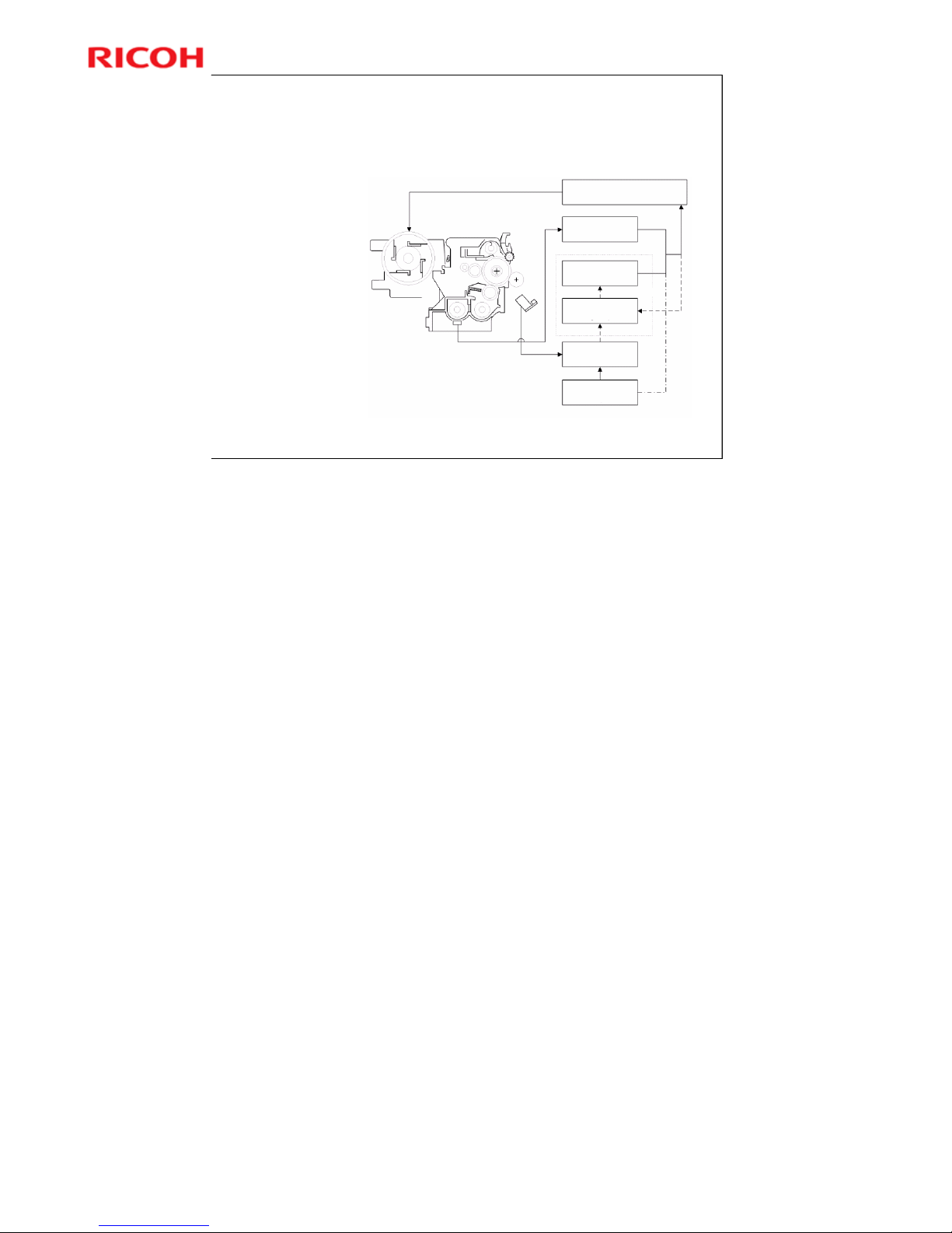
Toner Density Control – 1
Overview
Controlled by TD
and ID sensors.
There are four
modes but only
two can be used.
(See notes below
for details.)
Toner Supply Motor
On Time Calculation
TD Sensor
Output (Vt)
Vt Reference
Voltage (Vref)
Vt Reference
Voltage Update
ID Sensor Output
(Vsp/Vsg)
TD Sensor Initial
Setting (Vts)
New Vref
Vref Update
There are four modes for controlling toner supply which can be changed with by SP
2921. The factory setting is SP2921 = 0.
Basically, the toner concentration in the developer is controlled using the standard TD
sensor voltage (Vts), toner supply reference voltage (Vref), actual TD sensor output
voltage (Vt), and ID sensor output data (Vsp/Vsg).
The Four Modes
• Sensor Mode 1: SP2921 = 0, Normal sensor control mode
• Sensor Mode 2: SP2921 = 1, Design use only (don't use)
• Fixed Mode 1: SP2921 = 2, Design use only (don't use)
• Fixed Mode 2: SP2921 = 3: Use temporarily if the TD sensor needs to be replaced.
Page 64

Model K-C3.5L
64
R
i
c
o
h
C
o
.
L
t
d
.
h
t
t
p
:
/
/
w
w
w
.
r
i
c
o
h
.
c
o
m/
Slide 64
Toner Density Control – 2
Toner Density Sensor Initial Setting
The TD sensor initial setting (SP 2214: Developer
Initialize) procedure must be done after replacing
the developer. During TD sensor initial setting,
the TD sensor is set so that the TD sensor output
is the value of SP 2926 (default: 2.4 V). This
value will be used as the standard reference
voltage (Vts) of the TD sensor.
Toner Concentration Measurement
The toner concentration in the developer is
detected once every copy cycle. The sensor
output voltage (Vt) during the detection cycle is
compared with the standard reference voltage
(Vts) or the toner supply reference voltage (Vref).
No additional notes.
Page 65

Model K-C3.5L
65
R
i
c
o
h
C
o
.
L
t
d
.
h
t
t
p
:
/
/
w
w
w
.
r
i
c
o
h
.
c
o
m/
Slide 65
Toner Density Control – 3
Vsp/Vsg Detection
The ID sensor detects the following voltages.
Vsg: The ID sensor output when checking the drum surface
Vsp: The ID sensor output when checking the ID sensor
pattern
In this way, the reflectivity of both the drum surface and the
pattern on the drum are checked, compensating for any
variations in the reflectivity of the ID sensor pattern or the
reflectivity of the drum surface.
The ID sensor pattern is made on the drum by the charge roller
and laser diode.
Vsp/Vsg is not detected every page or job; it is detected during
warm-up at power on to decide Vref. This is done if the machine
starts warming up when the fusing temperature is 30C or less
(default) after entering night mode or low power mode (SP 2994
specifies the temperature setting).
No additional notes.
Page 66

Model K-C3.5L
66
R
i
c
o
h
C
o
.
L
t
d
.
h
t
t
p
:
/
/
w
w
w
.
r
i
c
o
h
.
c
o
m/
Slide 66
Toner Density Control – 4
Toner Supply Reference Voltage (Vref) Determination
The toner supply reference voltage (Vref) is used for toner
supply determination (see below). Vref is determined using
the following data:
» ID sensor output (Vsp/Vsg)
» (Vts or the current Vref) – Vt
Toner Supply Determination
The reference voltage (Vts or Vref) is the threshold voltage
for determining whether or not to supply toner. If Vt
becomes greater than the reference voltage, the machine
supplies additional toner.
This can be checked using SP 2220.
Toner Supply ON Time
Sensor supply mode on time can be adjusted with SP2922
and 2923.
Fixed supply mode on time can be adjusted with SP2922
and 2923.
No additional notes.
Page 67

Model K-C3.5L
67
R
i
c
o
h
C
o
.
L
t
d
.
h
t
t
p
:
/
/
w
w
w
.
r
i
c
o
h
.
c
o
m/
Slide 67
Abnormal Sensor Conditions
ID sensor
If ID sensor output is out of spec, machine disregards
output from sensor, and uses a Vref of 2.5 V.
After replacing ID sensor, reset error counter with SP
7-992.
TD sensor
If TD sensor output is out of spec, machine changes
to fixed supply mode 2.
» Toner supply motor on always for 200 ms per page
Copying continues until a TD sensor error is detected
10 consecutive times.
Then SC 390 is generated and machine cannot be
used.
More on abnormal sensor conditions
ID Sensor
Readings are abnormal if any of the following conditions occur:
• Vsg 2.5V
• Vsg < 3.5V when maximum power (979) is applied
• Vsp 2.5V
• (Vsg – Vsp) < 1.0V
• Vt 4.5V or Vt 0.2V
The above ID sensor values can be checked using SP 2221.
When this is detected, the machine changes the value of Vref to 2.5 V then does the
toner density control process (in a similar way to sensor control mode 2).
No SC code is generated if the ID sensor is defective.
TD Sensor
The TD sensor output is checked every copy. If the readings from the TD sensor
become abnormal, the machine changes the toner density control mode to fixed supply
mode 2, and the toner supply amount per page is always 200 ms, r egardless of the
value of SP 2925. If the machine detects the TD sensor error condition 10 times
consecutively, an SC code is generated (SC390) and the machine must be repaired.
Page 68

Model K-C3.5L
68
R
i
c
o
h
C
o
.
L
t
d
.
h
t
t
p
:
/
/
w
w
w
.
r
i
c
o
h
.
c
o
m/
Slide 68
Toner Near-end/End Detection
No near-end or end sensors
Toner near-end/end are determined by TD sensor
output (current and reference voltages).
If near-end is detected, toner is added for a short
period (adjustable with SP 2 923).
If the toner level does not recover, toner end is
after 50 more copies (the number of copies is
adjustable with SP 2 213).
There is no toner end or near-end detection if the
machine is in fixed control 2 mode.
No additional notes.
Page 69

Model K-C3.5L
69
R
i
c
o
h
C
o
.
L
t
d
.
h
t
t
p
:
/
/
w
w
w
.
r
i
c
o
h
.
c
o
m/
Slide 69
Toner Near-end/End Detection - Details
If Vt level 6 is detected 5 consecutive times, near-end
is detected.
Toner is added after the copy job:
If supply recovers to Vt level 5, near-end is cancelled.
Otherwise, toner end occurs after 50 copies
If Vt level 7 is detected 3 consecutive times, toner end
is detected immediately.
Recovery after adding new toner
The machine must recover to Vt level 5 after a new
bottle has been added
No additional notes.
Page 70

Model K-C3.5L
70
R
i
c
o
h
C
o
.
L
t
d
.
h
t
t
p
:
/
/
w
w
w
.
r
i
c
o
h
.
c
o
m/
Slide 70
SP Modes - Development
SP 2201: Development bias (printing, ID sensor
pattern creation)
SP 2802: Forced developer agitation
No additional notes.
Page 71

Model K-C3.5L
71
R
i
c
o
h
C
o
.
L
t
d
.
h
t
t
p
:
/
/
w
w
w
.
r
i
c
o
h
.
c
o
m/
Slide 71
SP Modes - Toner Supply
SP 2221: ID sensor error display (Vsg, Vsp, Vt, etc if an ID
sensor error occurred)
SP 2908: Forced toner supply
SP 2921: Toner supply mode (sensor control, fixed control)
SP 2922: Toner supply motor on time (sensor control mode)
SP 2925: Toner supply motor on time
SP 2926: Adjusts Vts (target for TD sensor initialization
Sp 2927: Use of the ID sensor, enable/disable
No additional notes.
Page 72

Model K-C3.5L
72
R
i
c
o
h
C
o
.
L
t
d
.
h
t
t
p
:
/
/
w
w
w
.
r
i
c
o
h
.
c
o
m/
Slide 72
SP Modes - Toner Near-end/End
SP 2213: Number of copies between near-end and
end (20 or 50 - default: 50)
SP 2923: Toner supply motor on time during
recovery from end/near-end
SP 2928: Clears the toner end condition
Normally, do not use this, for the reasons explained
in the SP table.
No additional notes.
Page 73

Model K-C3.5L
73
R
i
c
o
h
C
o
.
L
t
d
.
h
t
t
p
:
/
/
w
w
w
.
r
i
c
o
h
.
c
o
m/
Slide 73
Lab Work
Remove the ID sensor.
FSM Æ Replacement and Adjustment Æ Image Transfer Æ
Image Density Sensor
No additional notes.
Page 74

Model K-C3.5L
74
R
i
c
o
h
C
o
.
L
t
d
.
h
t
t
p
:
/
/
w
w
w
.
r
i
c
o
h
.
c
o
m/
Slide 74
Model K-C3.5L
Service Training
11. Drum Cleaning & Toner Recycling
No additional notes.
Page 75
Model K-C3.5L
75
R
i
c
o
h
C
o
.
L
t
d
.
h
t
t
p
:
/
/
w
w
w
.
r
i
c
o
h
.
c
o
m/
Slide 75
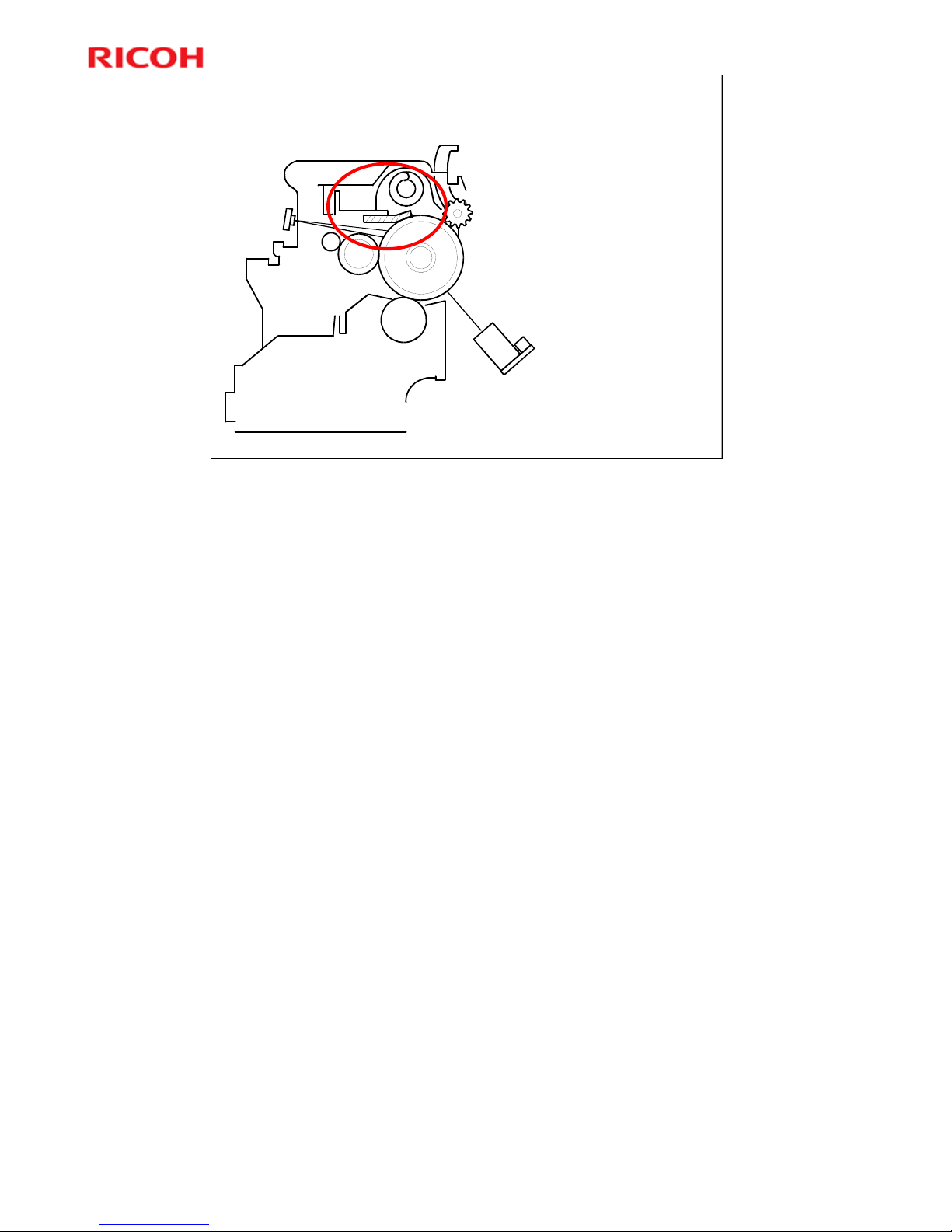
Drum Cleaning
Counter blade
system, no brush
Drum reverse
rotation to clean
blade’s edge
More on Drum Cleaning
This machine uses a counter blade, but no brush.
¾ The blade scrapes toner off the drum, and a toner collection coil picks up
toner from the top of the pile and carries it back to the development unit.
¾ At the end of every copy job, the drum reverses for 5 mm to scrape toner
off the edge of the cleaning blade.
Page 76
Model K-C3.5L
76
R
i
c
o
h
C
o
.
L
t
d
.
h
t
t
p
:
/
/
w
w
w
.
r
i
c
o
h
.
c
o
m/
Slide 76
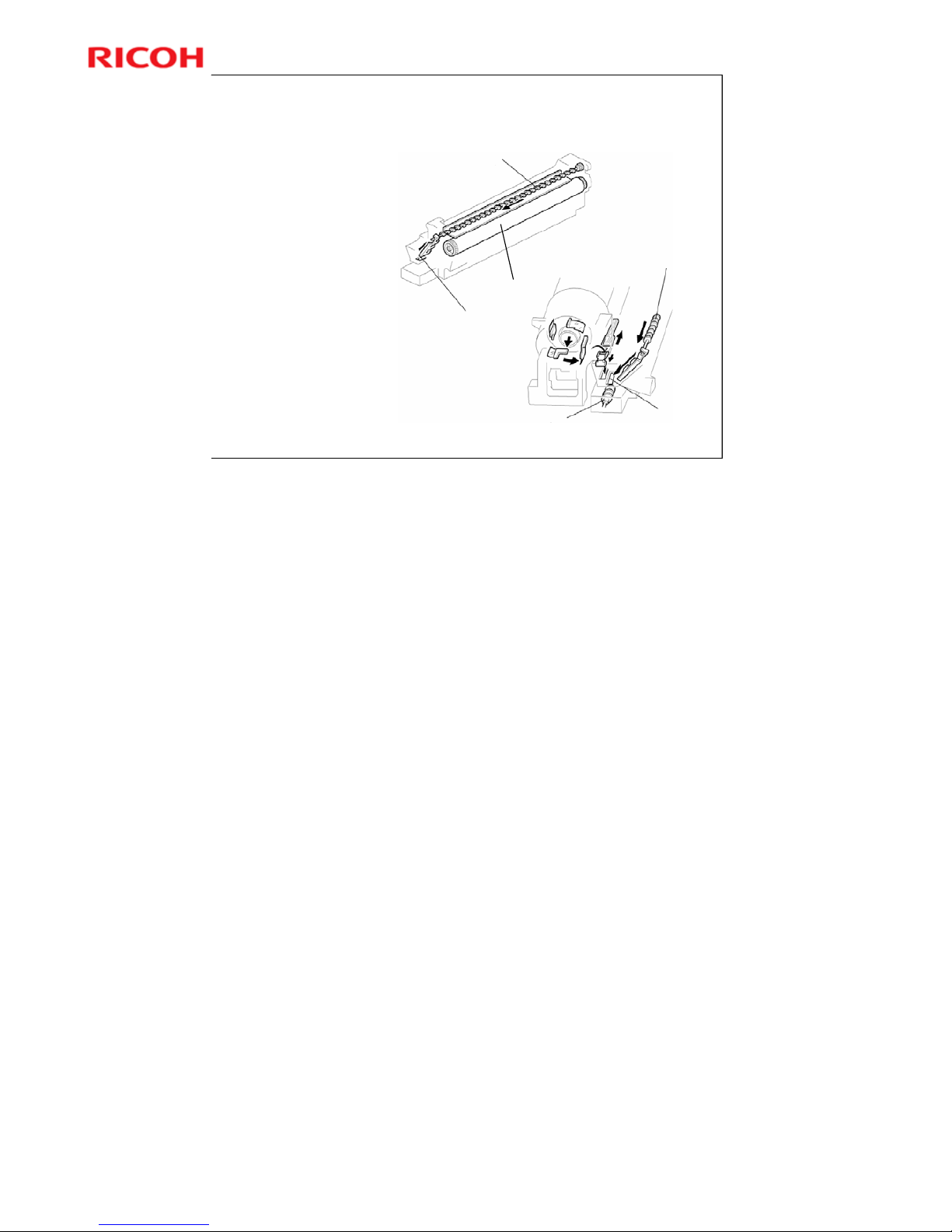
Toner Recycling
Toner collection coil:
Moves toner towards
the opening in the
PCU (Photo
Conductor Unit)
Drum
Toner collection coil
Toner collection coil
Mixing augur 1
Opening
Opening
More on Toner Recycling
The slider with the two comb-like appendages on it is always vibrating.
¾ The comb-like appendages break up any blockages of toner.
Note the two slots in the development unit.
¾ The one on the left receives fresh toner from the cartridge.
¾ The one on the right receives the recycled toner.
¾ New and recycled toner are mixed together in the development unit.
Mixing auger 1 in the development unit mixes the recycled toner with fresh toner
from the bottle.
Toner adhering to the transfer roller is sent back to the drum, as we shall see in
the Transfer section of the course. This toner is in turn recycled to the
development unit. It may contain some small amounts of paper dust.
Page 77

Model K-C3.5L
77
R
i
c
o
h
C
o
.
L
t
d
.
h
t
t
p
:
/
/
w
w
w
.
r
i
c
o
h
.
c
o
m/
Slide 77
12. Transfer and Separation
Model K-C3.5L
Service Training
No additional notes.
Page 78
Model K-C3.5L
78
R
i
c
o
h
C
o
.
L
t
d
.
h
t
t
p
:
/
/
w
w
w
.
r
i
c
o
h
.
c
o
m/
Slide 78
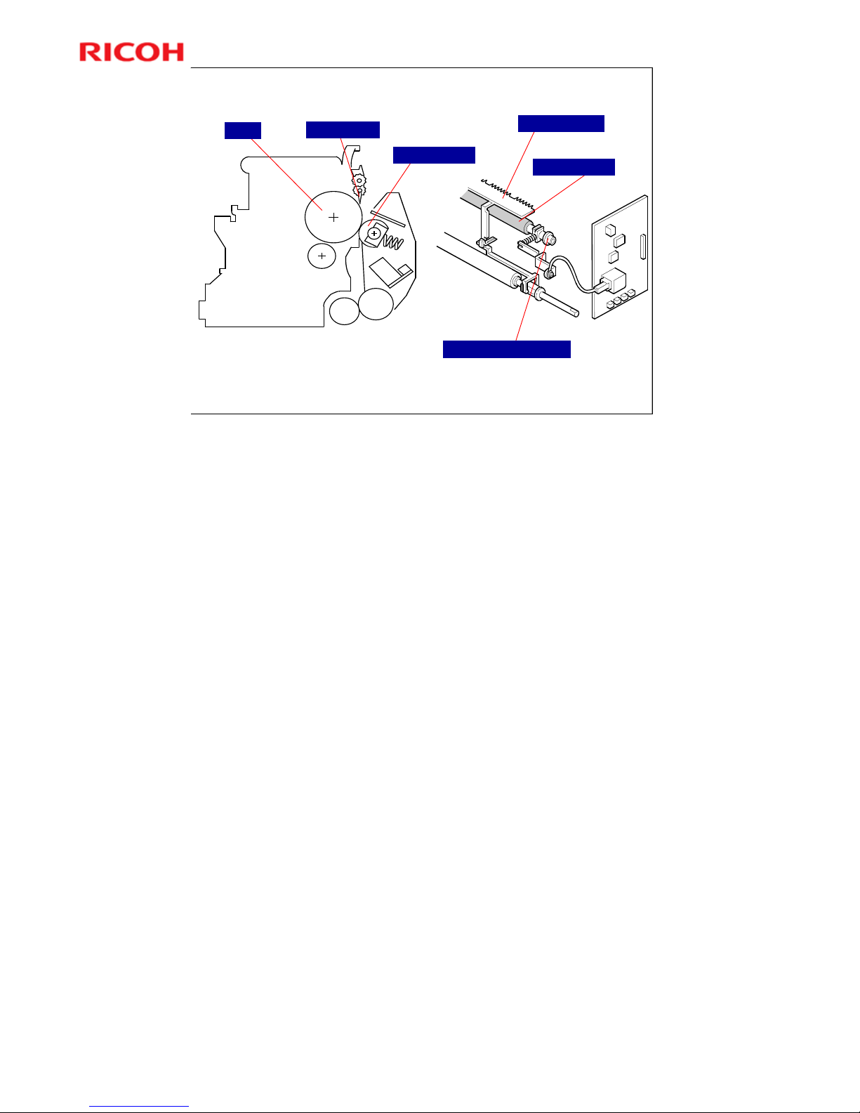
Overview
Transfer roller is always in contact with drum.
Drum curvature, pick-off pawl, and discharge plate separate paper from drum.
Transfer Roller
Discharge Plate
Pick-off Pawl
Transfer Roller
Transfer Roller Terminal
Drum
The discharge plate is grounded.
Page 79
Model K-C3.5L
79
R
i
c
o
h
C
o
.
L
t
d
.
h
t
t
p
:
/
/
w
w
w
.
r
i
c
o
h
.
c
o
m/
Slide 79
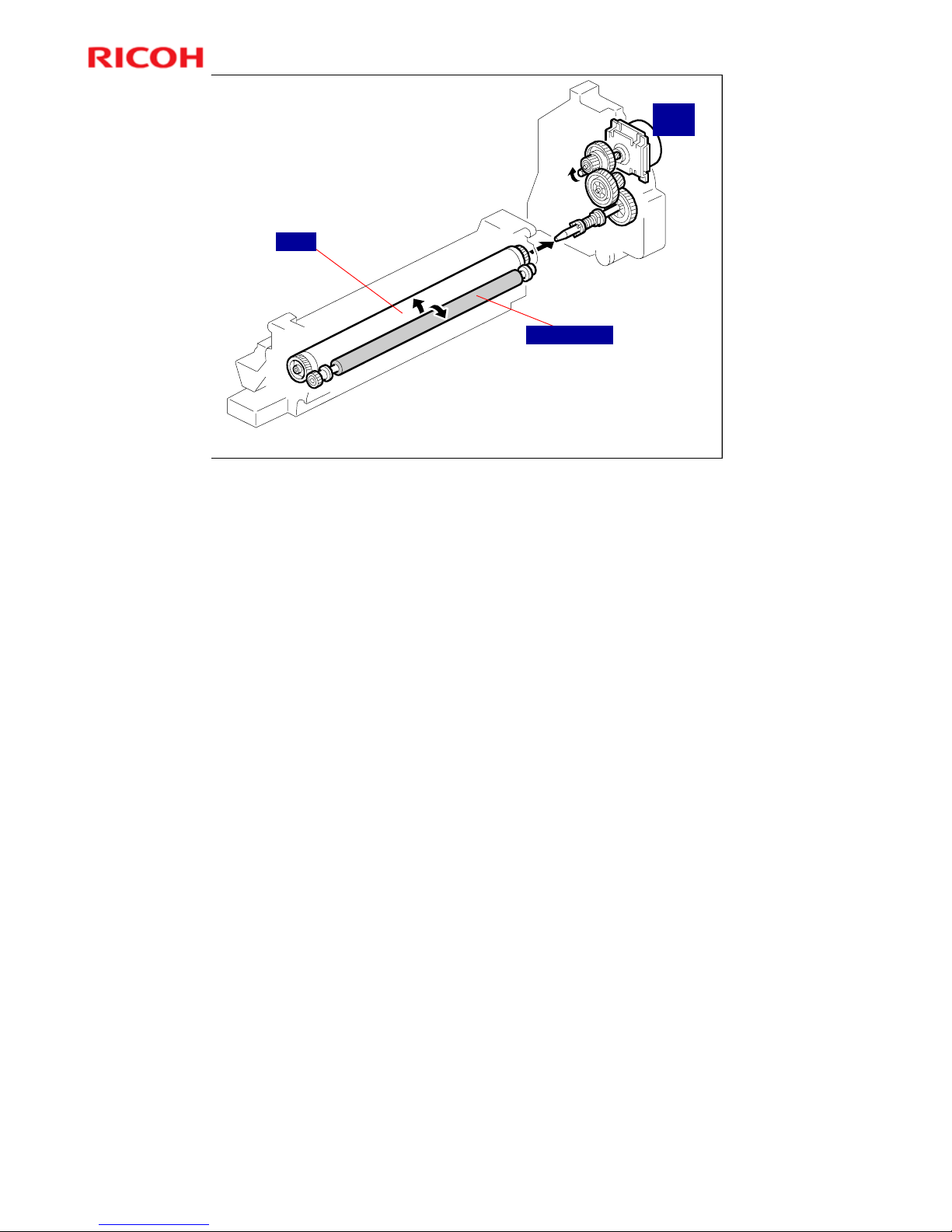
Drive
Drum drives Transfer Roller through gear.
Transfer Roller always contacts drum
There is no touch and release mechanism.
Main
Motor
Transfer roller
Drum
No additional notes.
Page 80

Model K-C3.5L
80
R
i
c
o
h
C
o
.
L
t
d
.
h
t
t
p
:
/
/
w
w
w
.
r
i
c
o
h
.
c
o
m/
Slide 80
Transfer Current
First, a low current (10 μA) is supplied at leading
edge (before print area).
Prevents positively charged toner remaining on
drum from transferring to roller.
Then high current is supplied (amount depends
on paper size and type).
This transfers toner to paper.
Finally, at trailing edge, either:
Multi-copy mode, between pages
» Low current is applied again.
Final page
» Transfer current is switched off.
No additional notes.
Page 81

Model K-C3.5L
81
R
i
c
o
h
C
o
.
L
t
d
.
h
t
t
p
:
/
/
w
w
w
.
r
i
c
o
h
.
c
o
m/
Slide 81
Transfer Roller Cleaning
Negative cleaning current is applied, followed by
positive current.
Negatively and positively charged toner particles
are both transferred back to drum.
Current for negative-charge phase can be
adjusted with SP 2301-4.
Three conditions for entering cleaning mode:
Before starting a job
» Default: Cleaning is not done before each job.
– Change with SP 2996 if required
Just after turning on power.
After a copy paper jam has been removed.
More on Transfer Roller Cleaning
Toner may transfer from drum to transfer roller if:
¾ A paper jam occurred
¾ The paper size is smaller than the printed image
The transfer roller must be cleaned to prevent toner from being transferred from
the roller to the back side of copies.
¾ There is no mechanism, just the application of positive and negative current
to transfer any adhering toner back to the drum.
The negative current pushes negatively-charged particles back to the
drum.
The positive current pushes positively-charged particles back to the
drum.
¾ Note that the roller is not cleaned before each job unless the setting of SP2-
996 is changed from the default. This is to keep the copy speed as high as
possible.
The toner that transfers back to the drum is recycled with the other unused toner.
Paper dust may also find its way into the toner because of this.
Page 82
Model K-C3.5L
82
R
i
c
o
h
C
o
.
L
t
d
.
h
t
t
p
:
/
/
w
w
w
.
r
i
c
o
h
.
c
o
m/
Slide 82
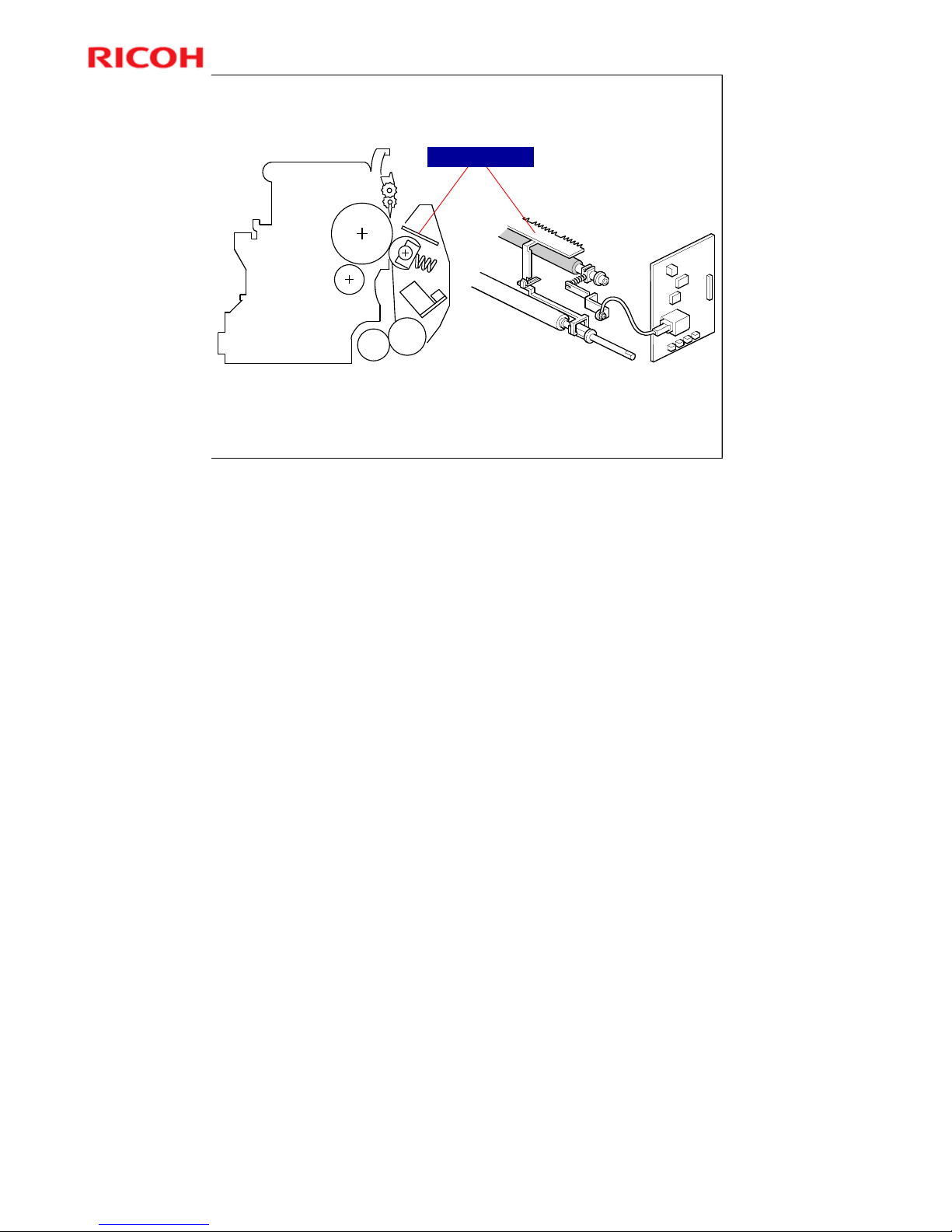
Separation
Drum curvature and Discharge Plate separate paper from drum.
There is no adjustment for discharge voltage in this machine, because
discharge plate is grounded.
Discharge Plate
No additional notes.
Page 83

Model K-C3.5L
83
R
i
c
o
h
C
o
.
L
t
d
.
h
t
t
p
:
/
/
w
w
w
.
r
i
c
o
h
.
c
o
m/
Slide 83
SP Modes
SP 2301: Transfer current
SP 2301 1: Paper tray
» 'Normal’ paper
SP 2301-2: By-pass tray
» For special/thick paper
SP 2301-4: During transfer roller cleaning
SP 2906: Image writing position shift
SP 2996: Transfer roller cleaning before each job,
on/off
No additional notes.
Page 84

Model K-C3.5L
84
R
i
c
o
h
C
o
.
L
t
d
.
h
t
t
p
:
/
/
w
w
w
.
r
i
c
o
h
.
c
o
m/
Slide 84
13. Paper Feed
Model K-C3.5L
Service Training
No additional notes.
Page 85
Model K-C3.5L
85
R
i
c
o
h
C
o
.
L
t
d
.
h
t
t
p
:
/
/
w
w
w
.
r
i
c
o
h
.
c
o
m/
Slide 85
Overview
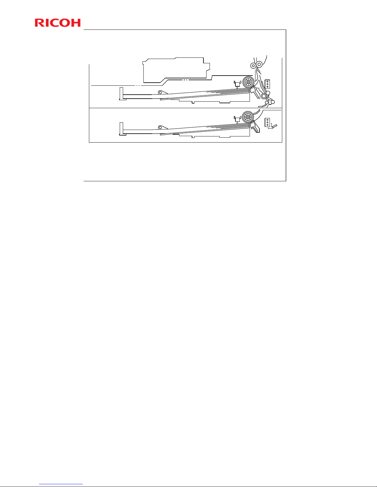
Built-in paper trays: 250 sheets each
Friction pad and feed roller system
By-pass tray: Up to 100 sheets
More on Overview
Note that the paper feed roller and shaft come out with the tray when the user
pulls the tray out. This prevents paper from getting caught inside the machine
when the tray is pulled out.
Note the functions of the two relay sensors.
The by-pass tray is not shown on the diagram.
The by-pass tray can handle thick paper (this mode is also for OHPs) and
‘special’ paper (meaning envelopes, traditional Japanese paper, etc.).
¾ The machine does not change the fusing, transfer, or other parameters if
the user selects ‘special paper’.
Choose “Special Paper” from the driver when printing from a tray that is
set up for ‘special paper’. Otherwise, the job will not print.
Trays set up for ‘special paper’ will be skipped for Auto Continue
Page 86
Model K-C3.5L
86
R
i
c
o
h
C
o
.
L
t
d
.
h
t
t
p
:
/
/
w
w
w
.
r
i
c
o
h
.
c
o
m/
Slide 86
Paper Feed Drive
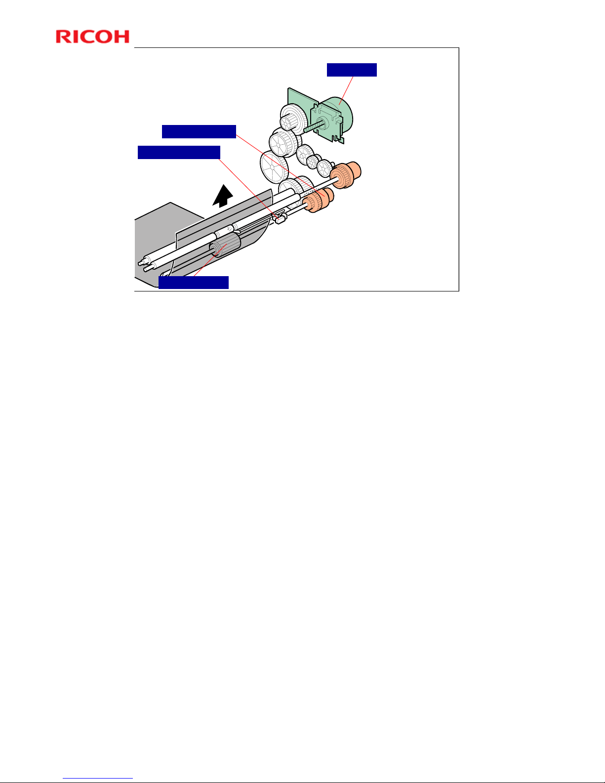
Main motor drives
pick-up and feed
mechanism.
Paper feed
clutches transfer
main motor drive to
paper feed roller.
When paper feed
clutch turns on,
feed roller starts to
feed paper.
Paper feed clutch
stays on until
shortly after
registration sensor
has been activated.
Paper feed roller
Paper feed clutch
Registration sensor
Main Motor
No additional notes.
Page 87
Model K-C3.5L
87
R
i
c
o
h
C
o
.
L
t
d
.
h
t
t
p
:
/
/
w
w
w
.
r
i
c
o
h
.
c
o
m/
Slide 87
Feed and Separation
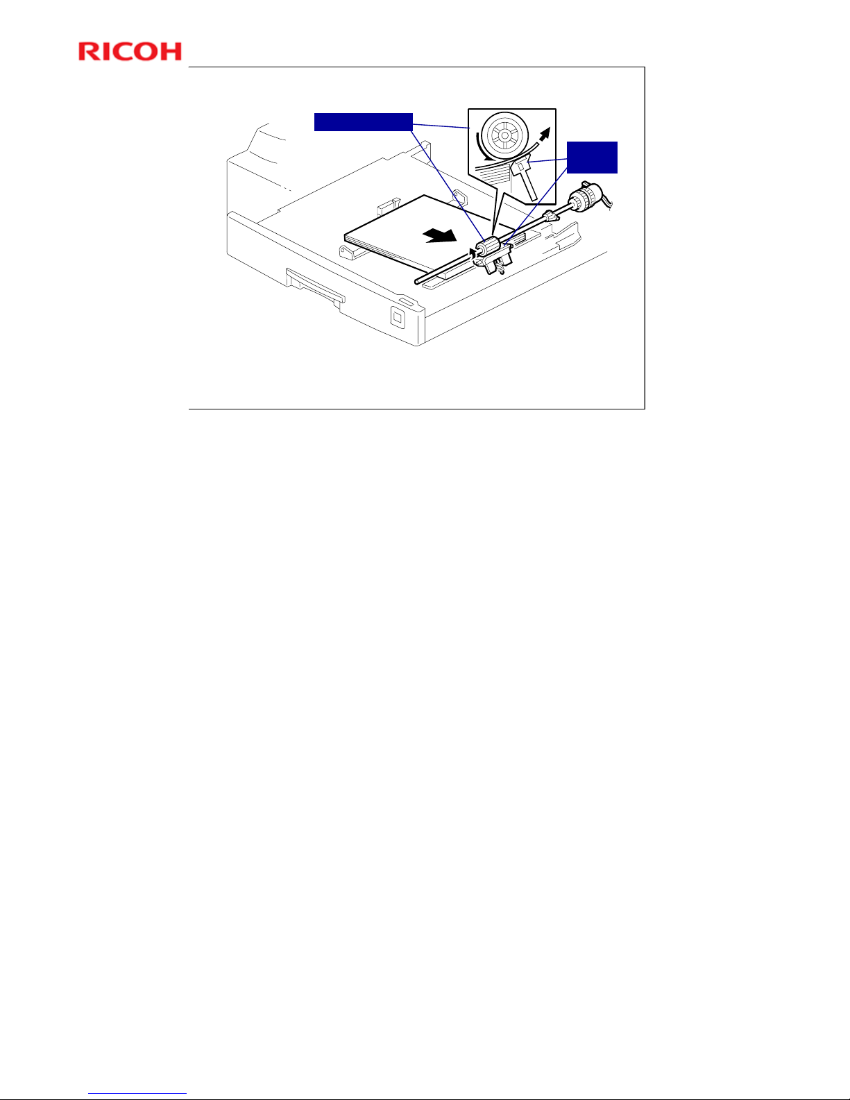
Feed roller and friction pad system.
Pressure of friction pad not adjustable.
Paper feed roller
Friction
pad
No additional notes.
Page 88
Model K-C3.5L
88
R
i
c
o
h
C
o
.
L
t
d
.
h
t
t
p
:
/
/
w
w
w
.
r
i
c
o
h
.
c
o
m/
Slide 88
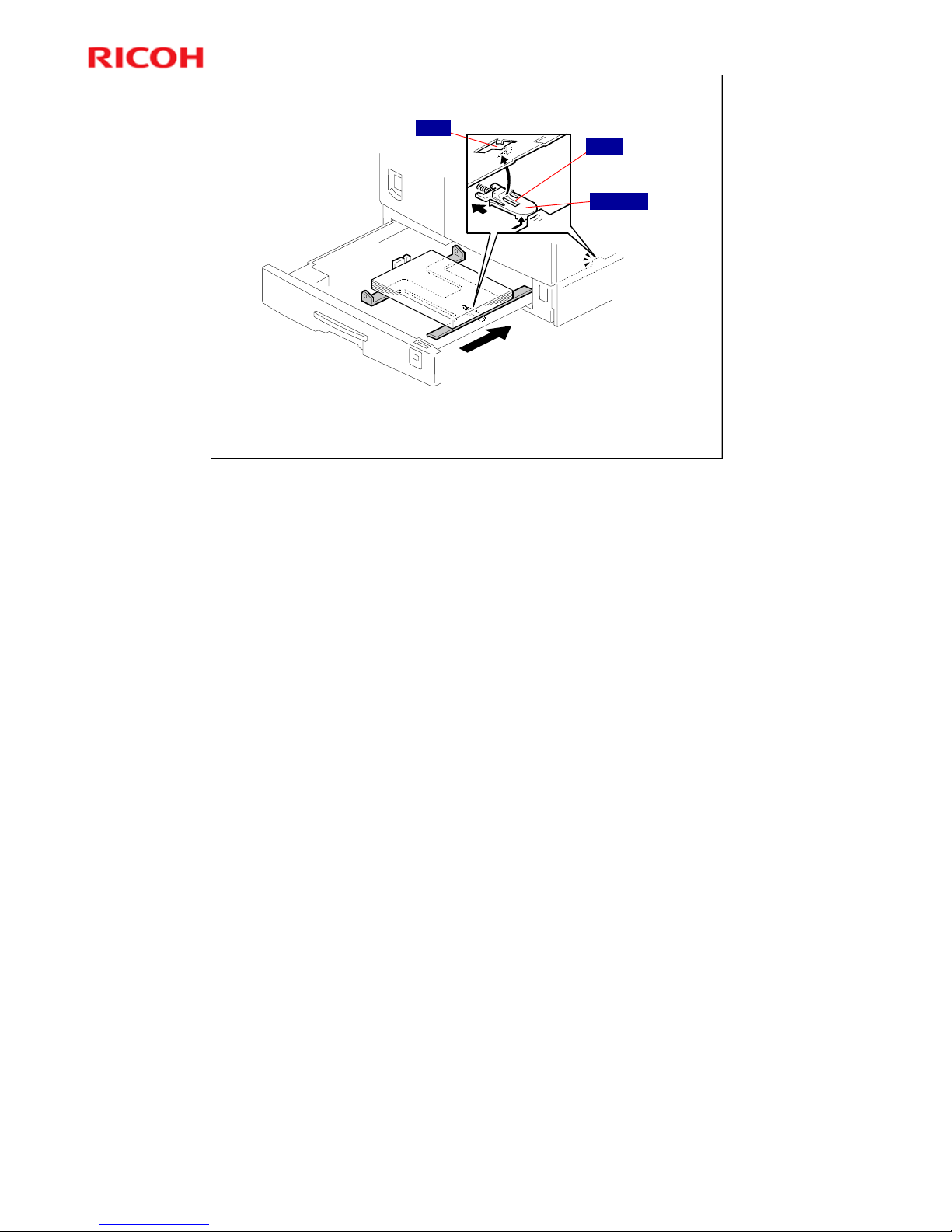
Tray Lift
When the tray is closed, projection on copier frame pushes slider off
bottom plate hook.
Slider is on bottom part of tray.
After slider comes off, compressed springs lift bottom plate.
Hook
Slider
Projection
No additional notes.
Page 89
Model K-C3.5L
89
R
i
c
o
h
C
o
.
L
t
d
.
h
t
t
p
:
/
/
w
w
w
.
r
i
c
o
h
.
c
o
m/
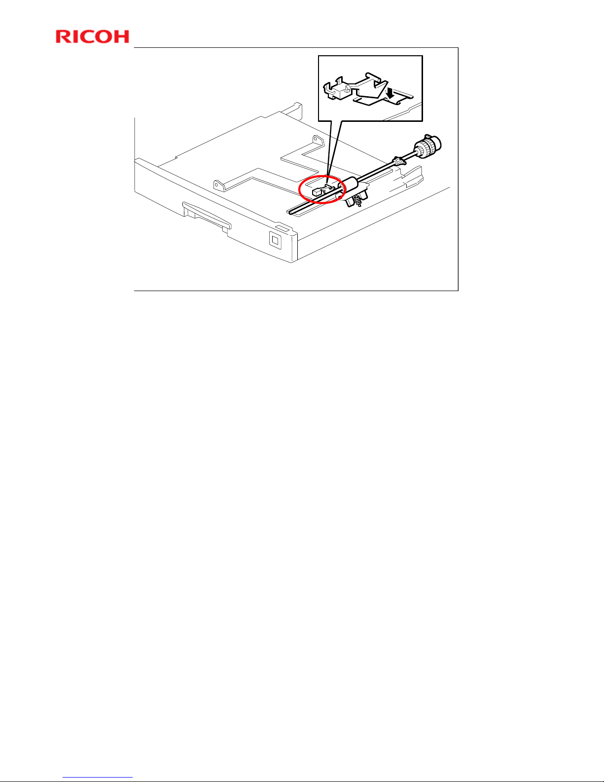
Slide 89
Paper end sensor feeler falls through slot in bottom plate when there
is no paper.
Paper End
Detection
No additional notes.
Page 90
Model K-C3.5L
90
R
i
c
o
h
C
o
.
L
t
d
.
h
t
t
p
:
/
/
w
w
w
.
r
i
c
o
h
.
c
o
m/
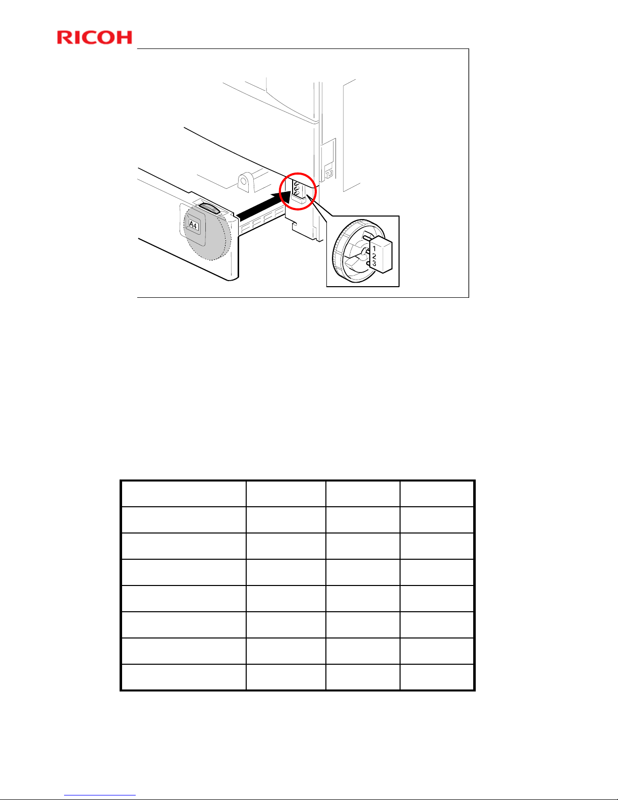
Slide 90
Paper Size Detection - Paper Tray
Dial and
microswitch mechanism.
Paper size sensor
detects position of dial
selected by user
User must
set dial to correct size.
(Size table is in the notes
below.)
More on Paper Size Detection
Using a non-standard paper size
To use a non-standard paper size, set the dial to the * mark
Then, set the size with a User Tool (System Settings – Tray Paper Settings –
Tray Paper Size).
The machine disables paper feed from the tray if the paper s ize c annot be
detected (the paper size cannot be detected if the paper size actuator is broken
or if no tray is installed).
Paper size table
On = Not pushed, Off = Pushed
OnOffOff* (asterisk)
OffOnOff11" x 8½"
OnOffOn8½" x 13"
OnOnOffA5 LEF, 8½" x 14"
OffOffOnA4 SEF, 8½" x 11"
OffOnOnA4 LEF
OffOffOffA3, 11" x 17"
SW 3SW 2SW 1Paper Size
Page 91
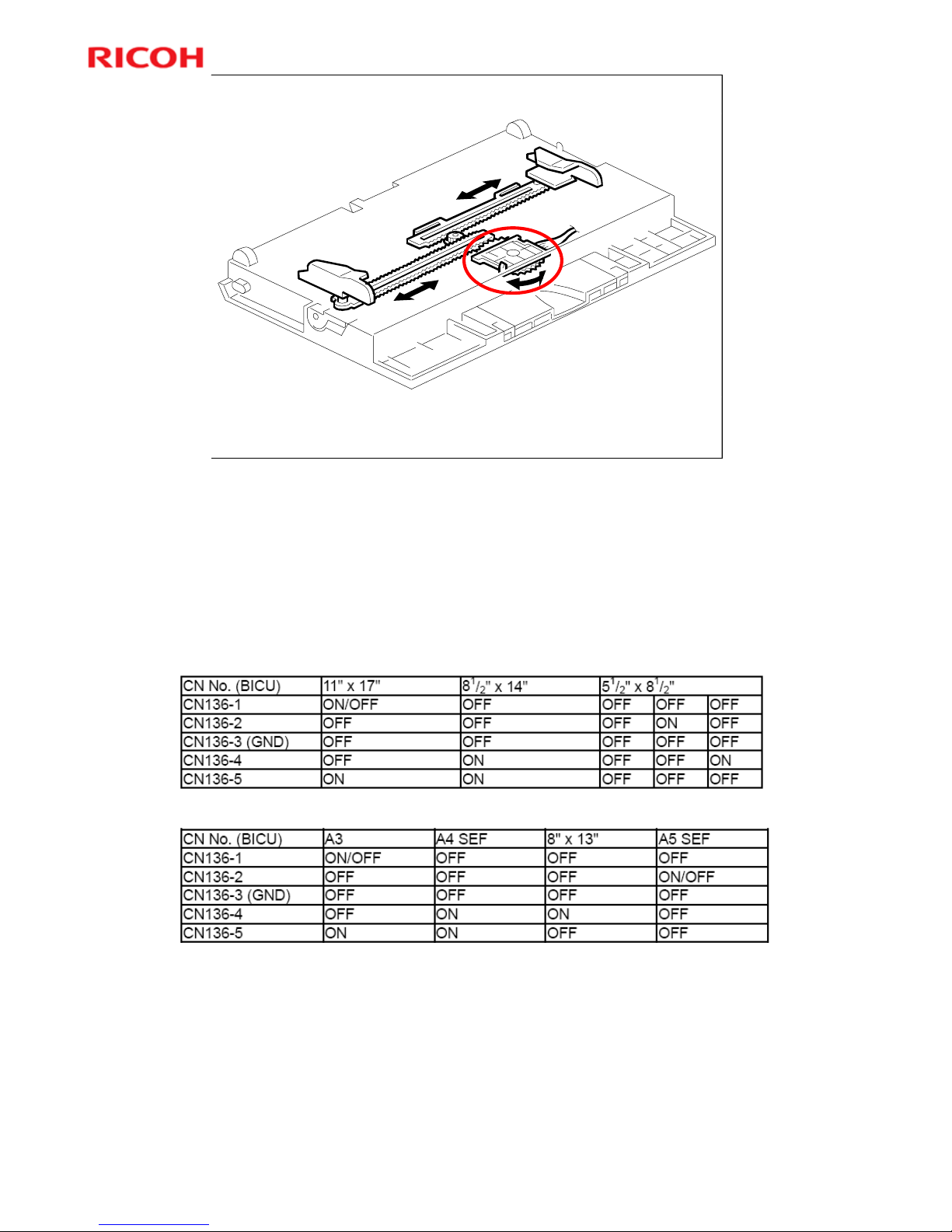
Model K-C3.5L
91
R
i
c
o
h
C
o
.
L
t
d
.
h
t
t
p
:
/
/
w
w
w
.
r
i
c
o
h
.
c
o
m/
Slide 91
Paper Size Detection - By-pass Tray
Bypass paper size switch monitors paper width.
Side fences turn a gear wheel that contains sensor terminals.
More on Paper Size Detection
The side guides contain ratchets that turn a gear wheel at the center of the
sensor. The gear wheel contains terminals. The output of the sensor changes
when the gear wheel rotates over the wiring patterns on the rectangular part of
the width sensor.
The bypass tray hardware only determines the paper width. The base copier
hardware determines the length.
North America
Europe/Asia
Page 92
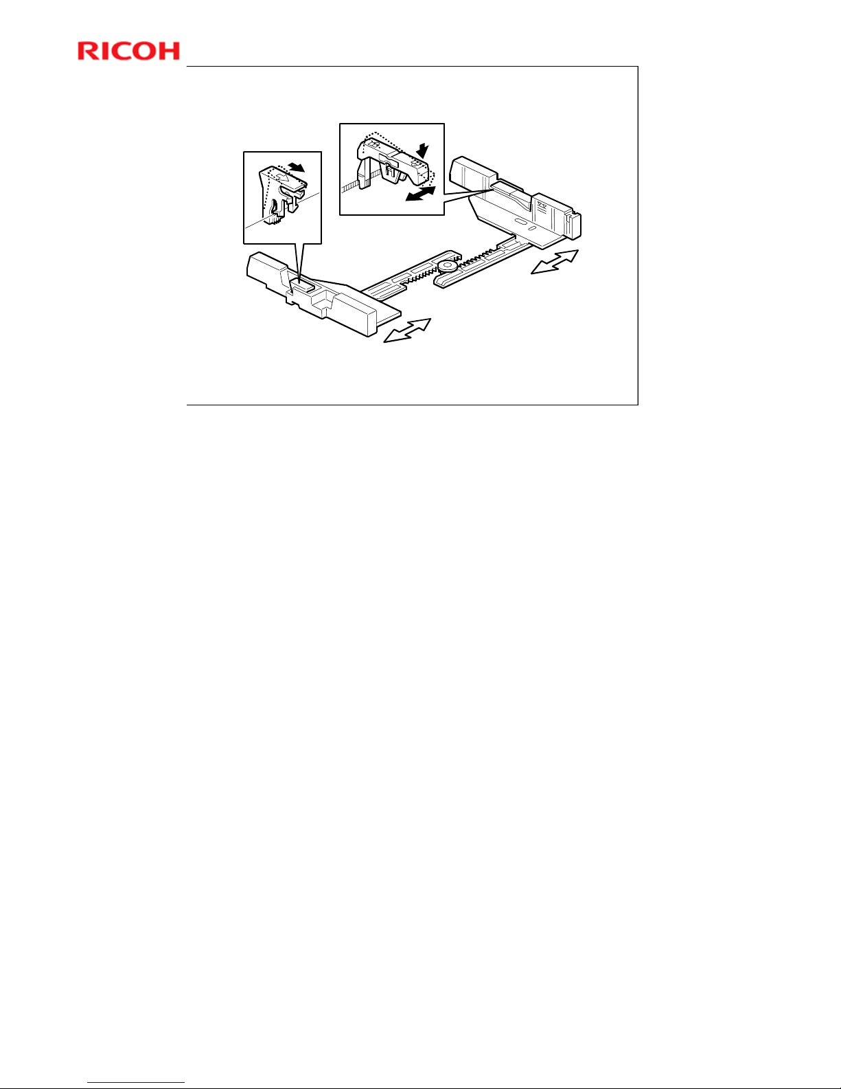
Model K-C3.5L
92
R
i
c
o
h
C
o
.
L
t
d
.
h
t
t
p
:
/
/
w
w
w
.
r
i
c
o
h
.
c
o
m/
Slide 92
Side Fences
Side fences have stoppers to prevent them from bending when a full
tray is pushed in too strongly
More on Side Fences
If the tray is full of paper and it is pushed in strongly, the fences may deform or
bend. This may cause the paper to skew or the side-to-side registration to be
incorrect.
Each side fence can be secured with a screw for customers who do not want to
change the paper size.
Page 93
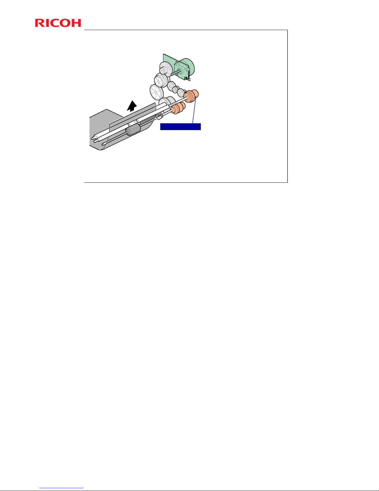
Model K-C3.5L
93
R
i
c
o
h
C
o
.
L
t
d
.
h
t
t
p
:
/
/
w
w
w
.
r
i
c
o
h
.
c
o
m/
Slide 93
Registration
Registration clutch
transfers drive
from main motor to
registration roller.
SP 1003 adjusts
amount of buckle
at registration roller
to prevent skew.
SP 1903: Adjusts
the amount of feed
from the feed roller
to help get paper
feed started after
registration
Registration Clutch
More on Registration
The paper feed clutch stays on slightly after the registration clutch turns off, so
that the paper buckles against the registration roller.
¾ SP 1003 can be used to adjust the amount of buckling.
The paper feed clutch can come on again to help paper feed get started after
registration. This is a good idea if there are frequent jams at the registration roller
just after registration.
¾ These jams occur when the paper jumps over the registration instead of
going between them. The clutch comes on again for certain paper types,
such as thick paper, to try to push the paper between the rollers.
¾ SP 1903 adjusts this feature.
¾ In lab tests, this problem was not found when feeding from tray 1. So there
is no adjustment for tray 1.
Page 94

Model K-C3.5L
94
R
i
c
o
h
C
o
.
L
t
d
.
h
t
t
p
:
/
/
w
w
w
.
r
i
c
o
h
.
c
o
m/
Slide 94
SP Modes
SP 1001: Leading edge registration for various paper
feed stations
SP 1002: Side-to-side registration for various paper
feed stations
SP 4010 - 11: Scanner registration
SP 6006: ADF registration
SP 1003: Paper feed timing.
(Adjusts buckle at the
registration roller to prevent skew.)
SP 1903: Feed clutch boost after registration
No additional notes.
Page 95

Model K-C3.5L
95
R
i
c
o
h
C
o
.
L
t
d
.
h
t
t
p
:
/
/
w
w
w
.
r
i
c
o
h
.
c
o
m/
Slide 95
Lab Work
Practice the removal procedures for the paper
feed section.
FSM Æ Replacement and Adjustment Æ Paper Feed
Section
No additional notes.
Page 96

Model K-C3.5L
96
R
i
c
o
h
C
o
.
L
t
d
.
h
t
t
p
:
/
/
w
w
w
.
r
i
c
o
h
.
c
o
m/
Slide 96
14. Fusing
Model K-C3.5L
Service Training
No additional notes.
Page 97
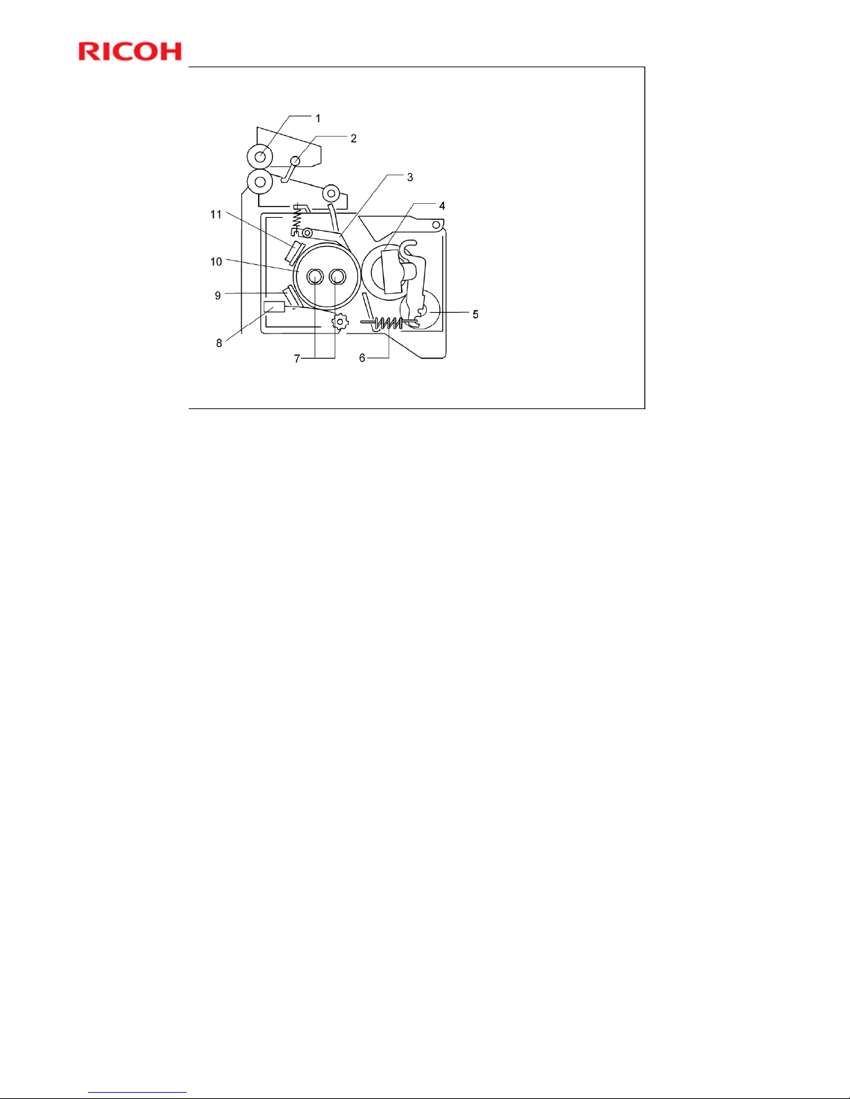
Model K-C3.5L
97
R
i
c
o
h
C
o
.
L
t
d
.
h
t
t
p
:
/
/
w
w
w
.
r
i
c
o
h
.
c
o
m/
Slide 97
Overview
Two fusing lamps
Not identical
Pressure Roller has
a Cleaning Roller
Thin-walled hot
roller
No oil supply
mechanism
Components
1. Paper exit roller
2. Exit sensor
3. Hot roller strippers
4. Pressure roller
5. Cleaning roller
6. Pressure spring
7. Fusing lamps
8. Thermistor
9. Thermostat
10.Hot roller
11.Thermostat
Page 98
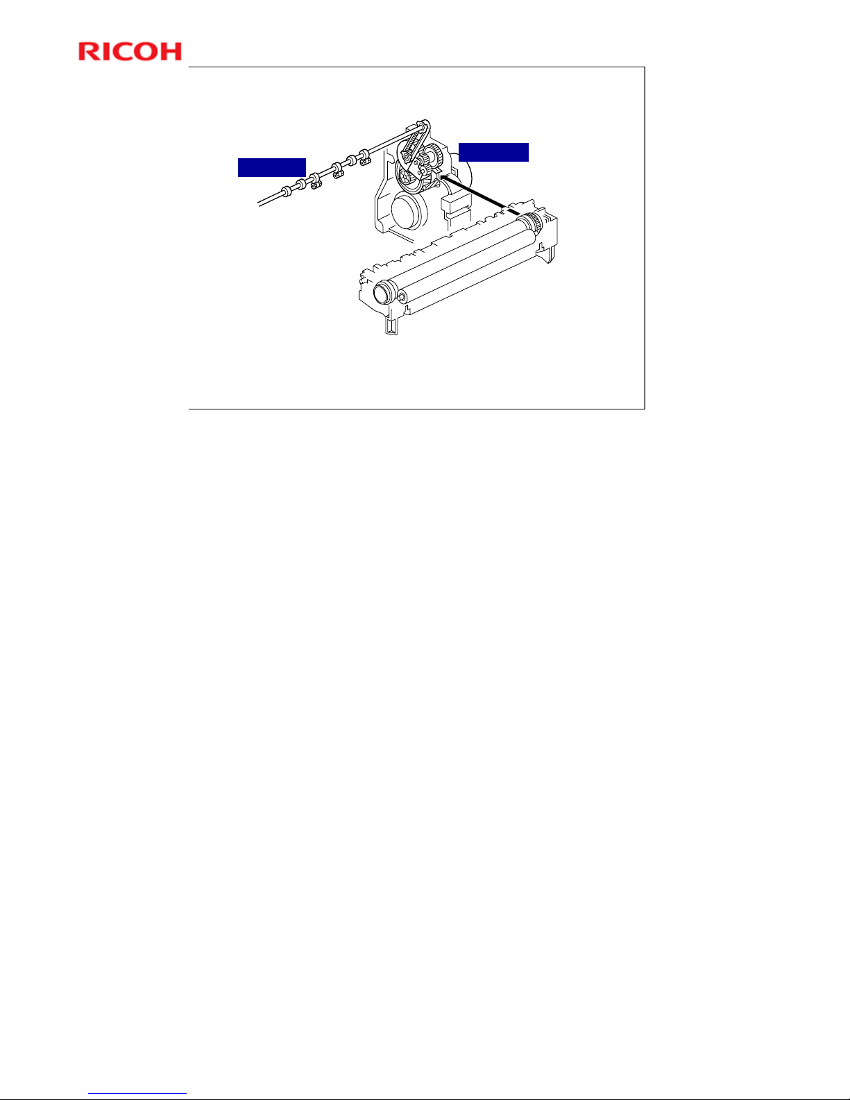
Model K-C3.5L
98
R
i
c
o
h
C
o
.
L
t
d
.
h
t
t
p
:
/
/
w
w
w
.
r
i
c
o
h
.
c
o
m/
Slide 98
Fusing unit is driven by main motor through gears.
Paper exit rollers are driven by main motor through a timing belt.
Main motor
Exit rollers
Drive
No additional notes.
Page 99
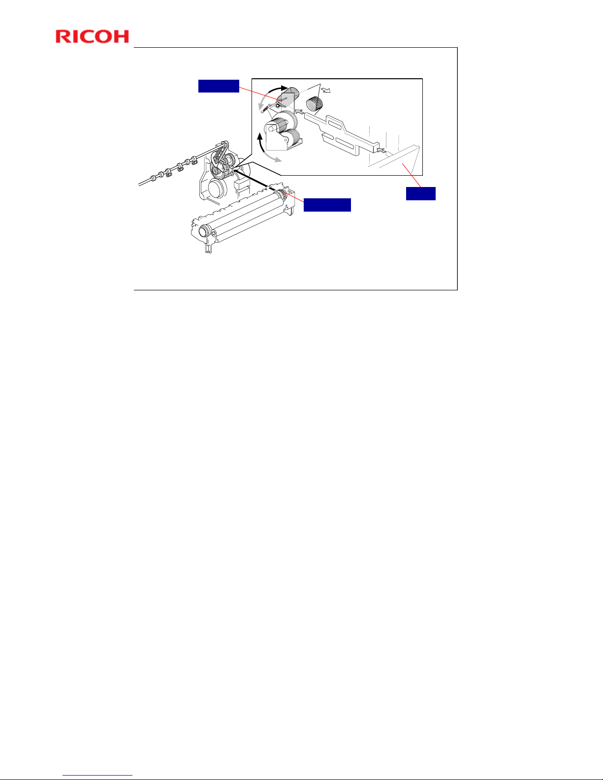
Model K-C3.5L
99
R
i
c
o
h
C
o
.
L
t
d
.
h
t
t
p
:
/
/
w
w
w
.
r
i
c
o
h
.
c
o
m/
Slide 99
Automatic Pressure Release
Fusing unit drive gear disengages when cover is open for easier jam removal
Fusing drive release solenoid cuts drive to fusing unit during warm-up.
Drive Gear
Cover
Solenoid
More on Automatic Release
Pressure release when the cover is open
The drive gear releases when the cover is open, so that jams can be removed.
Pressure release during warm-up
During warm up (just after the main power is switched on, or from
standby/energy saver mode), if the temperature is above 18°C, the solenoid
turns on and disengages the drive gear, which cuts the drive to the fusing unit.
If the solenoid is off, the drive gear is engaged, and the hot roller turns whenever
the main motor is on. When the hot roller turns, it will be cooled down by the
pressure roller. So, the machine will take longer to detect the standby
temperature.
However, when the machine is cold (below 18°C), the hot roller turns so that it
will warm up evenly. Then, at 18°C, the roller will stop turning.
Note that if fusing idling is switched on (SP 1103), the solenoid will always
engage the drive gear and the rollers will turn, regardless of the temperature.
Page 100
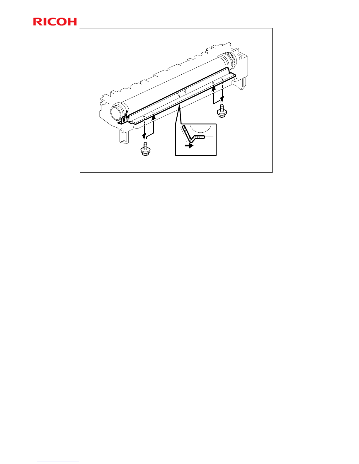
Model K-C3.5L
100
R
i
c
o
h
C
o
.
L
t
d
.
h
t
t
p
:
/
/
w
w
w
.
r
i
c
o
h
.
c
o
m/
Slide 100
If paper creases in fusing unit, move guide to right.
Fusing Entrance Guide Shaft
More on Entrance Guide Shaft
The entrance guide can be moved to prevent creasing.
Moving the guide to the right feeds the paper more directly to the gap between
the two rollers.
 Loading...