

Page 1

!
IMPORTANT SAFETY NOTICES
PREVENTION OF PHYSICAL INJURY
1. Before disassembling or assembling parts of the copier and peripherals,
make sure that the copier power cord is unplugged.
2. The wall outlet should be near the copier and easily accessible.
3. Note that some components of the copier and the paper tray unit are
supplied with electrical voltage even if the main power switch is turned off.
4. If any adjustment or operation check has to be made with exterior covers off
or open while the main switch is turned on, keep hands away from electrified
or mechanically driven components.
5. If the Start key is pressed before the copier completes the warm-up period
(the Start key starts blinking red and green alternatively), keep hands away
from the mechanical and the electrical components as the copier starts
making copies as soon as the warm-up period is completed.
6. The inside and the metal parts of the fusing unit become extremely hot while
the copier is operating. Be careful to avoid touching those components with
your bare hands.
HEALTH SAFETY CONDITIONS
1. Never operate the copier without the ozone filters installed.
2. Always replace the ozone filters with the specified ones at the specified
intervals.
3. Toner and developer are non-toxic, but if you get either of them in your eyes
by accident, it may cause temporary eye discomfort. Try to remove with eye
drops or flush with water as first aid. If unsuccessful, get medical attention.
OBSERVANCE OF ELECTRICAL SAFETY STANDARDS
1. The copier and its peripherals must be installed and maintained by a
customer service representative who has completed the training course on
those models.
2. The NVRAM on the system control board has a lithium battery which can
explode if replaced incorrectly. Replace the NVRAM only with an identical
one. The manufacturer recommends replacing the entire NVRAM. Do not
recharge or burn this battery. Used NVRAM must be handled in accordance
with local regulations.
1
Page 2
1. SAFETY AND ECOLOGICAL NOTES FOR DISPOSAL
Do not incinerate toner bottles or used toner. Toner dust may ignite
suddenly when exposed to an open flame.
2. Dispose of used toner, developer, and organic photoconductors in
accordance with local regulations. (These are non-toxic supplies.)
3. Dispose of replaced parts in accordance with local regulations.
4. When keeping used lithium batteries in or der to dispose of them later, do not
put more than 100 batteries per sealed box. Storing larger numbers or not
sealing them apart may lead to chemical reactions and heat build-up.
LASER SAFETY
The Center for Devices and Radiological Health (CDRH) prohibits the repair of
laser-based optical units in the field. The optical housing unit can only be repaired
in a factory or at a location with the requisite equipment. The laser subsystem is
replaceable in the field by a qualified Customer Engineer. The laser chassis is not
repairable in the field. Customer engineers are therefore directed to return all
chassis and laser subsystems to the factory or service depot when replacement of
the optical subsystem is required.
!
WARNING
Use of controls, or adjustment, or performance of procedures other than
those specified in this manual may result in hazardous radiation exposure.
!
WARNING
Turn off the main switch before attempting any of the procedures in the
Laser Unit section. Laser beams can seriously damage your eyes.
CAUTION MARKING:
2
Page 3
28 August, 2000 SPECIFICATIONS
1. OVERALL MACHINE INFORMATION
1.1 SPECIFICATIONS
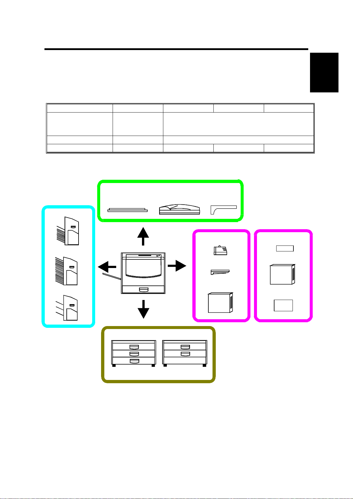
1.1.1 MACHINE CONFIGURATION
A258 / B018
Operation Panel
Paper Tray Unit
Edit Function
Sorter/Stapler
A555
A834
40-digit 4-line
LCD Hard Key
Type
500 sheets Duplex
No No Yes Option
Platen Cover
A749-01
Copier
144 mm x 192 mm (10.4 inch)
Color Touch Panel Display
A259 A260
ARDF
A663
Original Tray
A430-07
A258-259-260 copiers
FPU A846
FPU Table
A702-19
Overall
Information
B017
B017/018 copiers
Editing B380
I/F B381
A849
Paper Tray Unit (500 sheets/tray)
A833
A832
I/F A848
Fax B383
B017V501.WMF
1-1
Page 4
SPECIFICATIONS 28 August, 2000
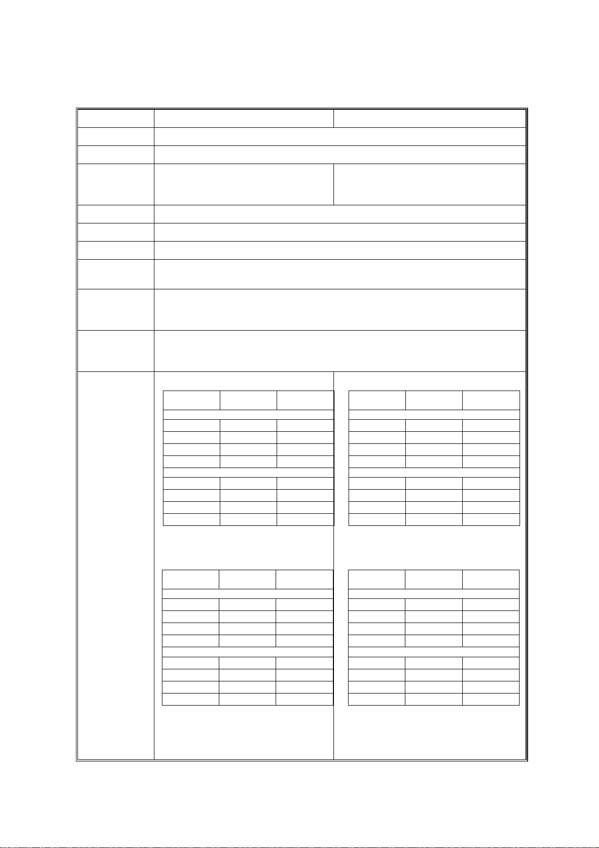
1.1.2 GENERAL SPECIFICATIONS
A258/A259/A260 B017/B018
Configuration Desktop
Copy Process Dry electrostatics transfer system
Resolution Scan: 400 dpi
Copy mode: 400 dpi
Print mode: 600 dpi
Gradations 256 gradations
Originals Sheet/Book/Object
Original Size Max.: 11”x17”/A3
Copy Paper
Size
Copy Paper
Weight
Paper tray: Max. 11”x17”/A3
By-pass: Max. 12”18”/305x457mm
Paper Tray: 17 to 28 lbs. / 63 to 105 g/m
By-pass: 14 to 43 lbs. / 52 to 160 g/m
Auto duplex: 17 to 28 lbs. / 63 to 105 g/m
Reproduction
Ratios (%)
LT: 400, 200, 155, 129, 121, 100, 93, 85, 78, 73, 65, 50, 25
A4: 400, 200, 141, 122, 115, 100, 93, 82, 75, 71, 65, 50, 25
LT & A4: Programmable: 2 user ratios / Zoom : From 25 to 400 in 1% step
Copy Speed
(cpm)
A258
81/2"x11"
(S) / A4(S)
Normal Mode
F/C
S/C (CMYK)
S/C (BG)
S/C (R)
OHP/Thick paper mode
F/C
S/C (CMYK)
S/C (BG)
S/C (R)
63
21 11
94.5
73.5
31.5
52.5
42
3.5 1.5
11"x17" /
A3
Scan: 600 dpi
Copy mode: 600 dpi
Print mode: 600 dpi
2
2
2
B018
Normal Mode
F/C
S/C (CMYK)
S/C (BG)
S/C (R)
OHP/Thick paper mode
F/C
S/C (CMYK)
S/C (BG)
S/C (R)
81/2"x11"
(S) / A4(S)
11"x17" /
A3
63
25 13
94.5
73.5
31.5
52.5
42
3.5 1.5
A259/A260
81/2"x11"
(S) / A4(S)
Normal Mode
F/C
S/C (CMYK)
S/C (BG)
S/C (R)
OHP/Thick paper mode
F/C
S/C (CMYK)
S/C (BG)
S/C (R)
B017
11"x17" /
A3
63
28 14
94.5
73.5
31.5
52.5
42
3.5 1.5
1-2
81/2"x11"
Normal Mode
F/C
S/C (CMYK)
S/C (BG)
S/C (R)
OHP/Thick paper mode
F/C
S/C (CMYK)
S/C (BG)
S/C (R)
(S) / A4(S)
31 15
3.5 1.5
11"x17" /
A3
63
94.5
73.5
31.5
52.5
42
Page 5
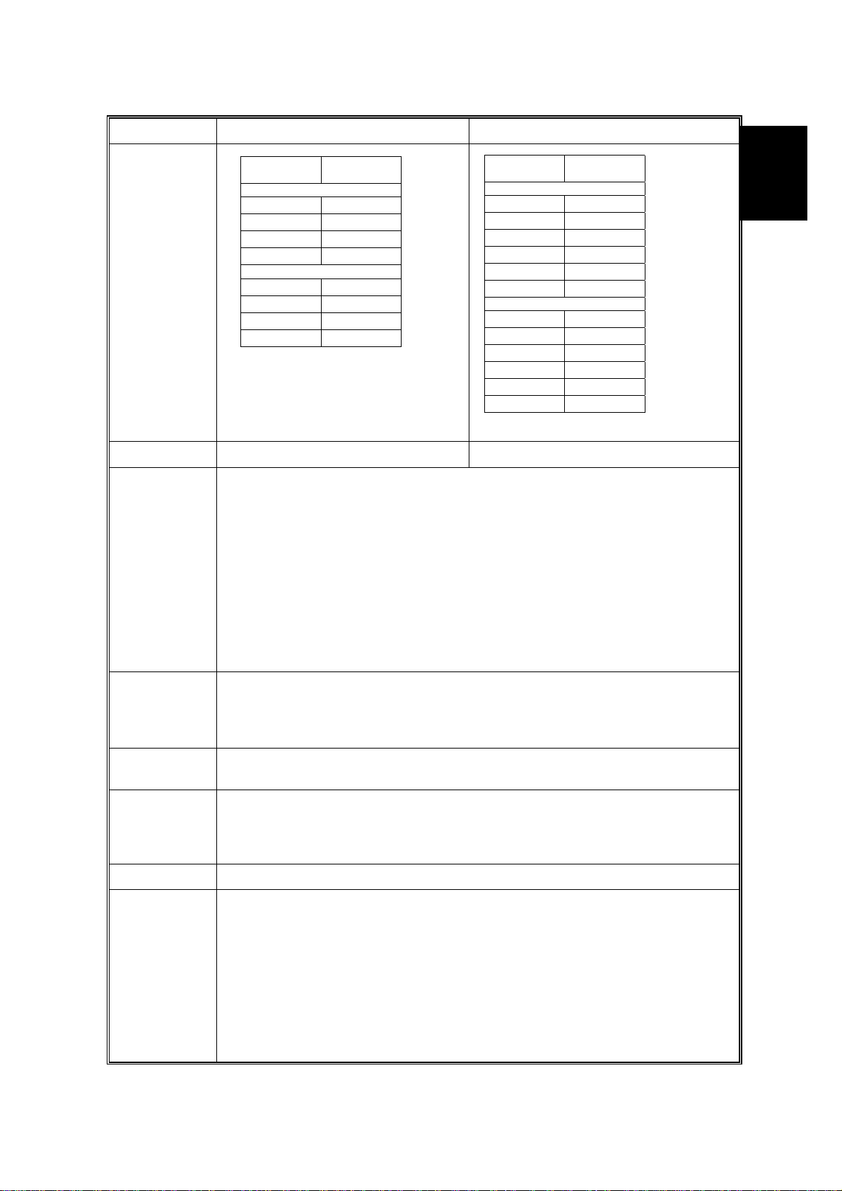
28 August, 2000 SPECIFICATIONS
A258/A259/A260 B017/B018
First Copy
Time
81/2"x11" (S) /
A4
Warm-up Time
Duplexing:
A258/B017:
Manual
Duplex
A259/A260/
B018:
Auto Duplex
81/2"x11"
Normal Mode
F/C
S/C (K)
S/C (CMY)
S/C (BGR)
OHP/Thick paper mode
F/C
S/C (K)
S/C (CMY)
S/C (BGR)
(S) / A4
22.4
8
10
16
35
23
25
27
Approx. 7 minutes (at 68°F / 20°C)
Manual duplexing in full color and single
color modes
Manual & auto duplexing in full color and
single color modes
Manual & auto duplexing in full color and
single color modes
Duplexing can be done on 64-105 g/m
2
81/2"x11"
Normal Mode
F/C
S/C (K)
S/C (CMY)
S/C (B)
S/C (G)
S/C (R)
OHP/Thick paper mode
F/C
S/C (K)
S/C (CMY)
S/C (B)
S/C (G)
S/C (R)
(S) / A4
22.4
8
10
19
16
16
35
23
25
30
27
27
Approx. 4.5 minutes (at 68°F / 20°C)
paper.
Overall
Information
Manual duplexing can be done through the
bypass table only, and the user should press
the Duplex Side 2 key before copying the reverse side.
NonReproduction
Area:
Leading edge: 0.2" ± 0.08" (5 mm ± 2 mm)
Side: 0.08" ± 0.08" (2 mm ± 2 mm)/
Total less than 0.16" (4 mm)
Trailing Edge: 2.0 mm + 2.0/-1.5 mm
Copy Number
Number keys, 1 to 99
Input
Copy Number
Input (Auto
Number keys
Single Color - 1 to 50: smaller than A3, 11" x 17"
Duplex)
Full Color 1 to 20: all sizes
Image Density Auto/Manual (9 steps)
Paper
Capacity
Tray:
500 sheets x 1 tray
(Manual Duplex Models: A258 / B018)
Bypass:
Normal paper (80 g/m
OHP 20 sheets
Adhesive paper 1 sheet
1 to 30: A3, 11" x17"
2
/20 lb.) 50 sheets
1-3
Page 6
SPECIFICATIONS 28 August, 2000
A258/A259/A260 B017/B018
Toner
Toner Addition (K, Y, C, M) (220 g/cartridge)
Replenishment
Copy Tray
100 sheets (11" x 17"/A3 and smaller)
Capacity
Power Source US: 120V/12A/60Hz,
Europe/Asia: 220-240V/8A/50,60 Hz
Taiwan: 110 V/12A/60Hz
Power
Consumption
Sound Power
Level
Maximum: 1.5 kVA
Average power consumption:
Stand-by 0.4 kW
Warm-up 1.3 kW
Copying 1.1 kW (B/W A4S)
Energy Saver Mode Value for standby minus 25W
Copier only Full system*
Stand-by Less than
55 dB (A)
Copying Less than
68 dB (A)
Full system:
Copier with document feeder, 500 sheets
x 3 trays unit, FPU, and a sorter stapler
0.6 kW (F/C A4S)
Less than
59 dB (A)
Less than
72 dB (A)
Copier only Full system*
Stand-by Less than
50 dB (A)
Copying Less than
68 dB (A)
Full system:
Copier with document feeder, 500 sheets x
3 trays unit, and a sorter stapler
Less than
54 dB (A)
Less than
72 dB (A)
Dimensions
(W/O Platen
Cover)
A258
A259
A260
Width Depth Height
620 mm
24.4"
620 mm
24.4"
620 mm
24.4"
680 mm
26.8"
757 mm
29.8"
757 mm
29.8"
602 mm
23.7"
602 mm
23.7"
602 mm
23.7"
Weight A258: 105 kg (231.3 lbs.)
A259/A260: 108 kg (237.9 lbs.)
Optional
Equipment
ARDF: A663
Sorter Stapler: A555 (10 bins)
A834 (20 bins)
Sorter: A849 (3 bins)
FPU: A846
FPU Holder: A702-19
Paper Tray Unit: A832 (2 trays)
A833 (3 trays)
I/F Unit: A848
RC-200: G528
Platen Cover: A749-01
Original Tray: A430-07
Key Counter
Width Depth Height
B018
B017
620 mm
24.4"
620 mm
24.4"
680 mm
26.8"
757 mm
29.8"
620 mm
24.4"
620 mm
24.4"
B018: 108 kg (237.6 lbs.)
B017: 112 kg (246.4 lbs.)
ARDF: A663
Sorter Stapler: A555 (10 bins)
A834 (20 bins)
Sorter: A849 (3 bins)
FPU: FPU Holder: Paper Tray Unit: A832 (2 trays)
A833 (3 trays)
I/F Unit: B381
RC-210: G549
Platen Cover: A749-01
Original Tray: A430-07
Key Counter
1-4
Page 7
28 August, 2000 SPECIFICATIONS
A258/A259/A260 B017/B018
- for B017 only –
Unique:
Edit Option: B380-01
Fax Option: B383
EXSAF Board: A818-10
HDD: A841-11
Fax Stamp(NA only): A563-17
Common with A230/231/232:
ISDN Unit: A816-27
PMU Board: A818-12
ISDN Unit: A816-27
Options: Compatibility Table
OK: Can be installed
N/A: Not applicable
ARDF ARDF A663 OK
Sorter
Tray
Fax
Other
10 Bin S/S A555 OK
20 Bin S/S A834 OK
3 Bin Sorter A849 OK
2 Tray Unit A832 OKPaper
3 Tray Unit A833 OK
FPU A846 OKFPU
FPU Table A702-19 OK
I/F (Type E) A848 OK N/AI/F
I/F (Type H) B381 N/A OK
RC-200 G528 OK N/AController
RC-210 G549 N/A OK OK
Fax Option B383 N/A OK
Fax HDD A841-11 N/A OK
Handset A841-13 N/A OK
G4 Option A816-17 N/A OK
JBIG Option A818-12 N/A OK
SAF Memory A818-10 N/A OK
Fax Stamp A563-17
Platen Cover A74 9-01 OK
Original Tray A430-07 OK
Edit Option B380 N/A OK
A258 A259 A260 B018 B017
NA
Overall
Information
N/A
N/A OK
1-5
Page 8

SPECIFICATIONS 28 August, 2000
1.1.3 PLATEN/ARDF ORIGINAL SIZE DETECTION
Size (width x length)
[mm]
A3 (297 x 420) L No Yes No Yes
B4 (257 x 364) L No Yes No Yes
A4 (210 x 297) L No Yes Yes Yes
A4 (297 x 210) S No Yes Yes Yes
B5 (182 x 257) L No Yes No Yes
B5 (257 x 182) S No Yes No Yes
A5 (148 x 210) L No No* No Yes
A5 (210 x 148) S No No No Yes
B6 (128 x 182) L No No No Yes
B6 (182 x 128) S No No No Yes
11" x 17" (DLT) Yes No Yes Yes
11" x 15" No No Yes No
10" x 14" No No Yes Yes
8.5" x 14" (LG) Yes No Yes No
8.5" x 13" (F4) No No Yes Yes
8.25" x 13" No No No No
8" x 13"(F) No Yes Yes No
8.5" x 11" (LT) Yes No Yes Yes
11" x 8.5" (LT) Yes No Yes Yes
8" x 10.5" No No No No
8" x 10" No No Yes No
5.5" x 8.5" (HLT) No* No Yes No
8.5" x 5.5" (HLT) No No Yes No
A6 (105 x 148) L No No No No
Inches Metric Inches Metric
Platen ARDF
*: When the message “Cannot detect original size” appears use SP4-303 to detect
original sizes as A5 lengthwise/HLT.
*: This SP mode is only applic able for B017/018 copiers.
1-6
Page 9

28 August, 2000 SPECIFICATIONS
1.1.4 COPY PAPER SIZE
Size
(width x length)
[mm]
Trays in the main body
Paper Tray
(A258/B018)
Duplex Tray
(A259/A260/B017)
Inches Metric Inches Metric
By-
pass
All
versions
Optional
Sort/Stap.
A3 (297 x 420) L No Yes Yes Yes Yes Yes
B4 (257 x 364) L No Yes Yes Yes Yes Yes
A4 (210 x 297) L Yes Yes Yes Yes Yes Yes
A4 (297 x 210) S Yes Yes Yes Yes Yes Yes
B5 (182 x 257) L No Yes No Yes Yes Yes
B5 (257 x 182) S No Yes No Yes Yes Yes
A5 (148 x 210) L No Yes No No Yes Yes (1)
A5 (210 x 148) S No No Yes Yes Yes Yes (2)
B6 (128 x 182) L No No No No Yes Yes (1)
B6 (182 x 128) S No No No No No No
12” x 18” No No No No Yes Yes (3)
11" x 17" (DLT) Yes Yes Yes Yes Yes Yes
11" x 15" Yes No Yes No Yes Yes
10" x 14" Yes No Yes No Yes Yes
8.5" x 14" (LG) Yes No Yes No Yes Yes
8.5" x 13" (F4) Yes Yes Yes Yes Yes Yes
8.25" x 13" No No Yes Yes Yes Yes
8" x 13"(F) No No Yes Yes Yes Yes
8.5" x 11" (LT) Yes Yes Yes Yes Yes Yes
11" x 8.5" (LT) Yes Yes Yes Yes Yes Yes
8" x 10.5" No No Yes No Yes Yes
8" x 10" Yes No Yes Yes Yes Yes
5.5" x 8.5" (HLT) No No No No Yes Yes (1)
8.5" x 5.5" (HLT) Yes No Yes Yes Yes Yes (2)
A6 (105 x 148) L No No No No Yes Yes (2)
Overall
Information
Yes (1): Stapling is not possible.
Yes (2): Only with the proof tray. Sorter bins cannot be used.
Yes (3): 20-bin sorter (A834): Stapling is not possible.
10-bin sorter (A555): Not available
1-7
Page 10

SPECIFICATIONS 28 August, 2000
1.1.5 APS PAPER SIZES AVAILABLE
— For metric machines —
Zoom.
Ratios
A3
B4
A4L
B5L
A5L
A4S
B5S
A5S
8.5
x 11
11
x 8.5
8.5
x 13
11
x 15
200
173
163
141
122
115
100
93
87
82
75
71
65
61
57
~
~
~
~
~
~
~
~
~
~
~
~
~
174
164
142
123
116
101
94
88
83
76
72
66
——————A3—B4——A4L
8.5
—————A3B4——A4L
———A3B4—A4L
——A3B4—A4LB5L——A5L——————
A3B4—A4LB5L—A5L—————————
——————
S
A4SB5
—
—————
———
— — — — — —
— — — — — —
————A3—
— — — — — —
A4SB5
8.5
B5L——A5L————
x13
A4
S
S
A5
S
8.5
x11
11
x8.5
8.5
x13
11
x15
B5
—
——
—————————
— — — — — — — — —
— — — — — — — — —
——A4LB5L————A5L
— — — — — — — — —
S
——
A5
S
B5L — — A5L —
x13
A5
S
——————
~
62
58
8.5
B5L — A5L
x13
————
50
~
51
~
: Unavailable in platen cover mode. L: Lengthwise S: Sideways
— For standard machines (in inches)—
Zoom
Ratios
11x17
11x15
8.5x14
8.5x11
5.5
x8.5
8.5
x5.5
11x8.5
8x10
10x14
8x13
200
~
177
—————11x1711x1711x15
— — — — — 11x15 11x15 —
————
— — 11x17 —
11
x17
———
—————
— — — 11x17 10x14 8x10 — — — —
—————10x14—
———11x17—8x13————
176
~
156
11
x15
155
~
130
8.5
x14
129
~
122
8.5
x11
11
x8.5
121
~
101
11
x17
—
—
100
~
94
8.5
x14
8.5
x11
5.5
x8.5
8.5
x5.5
11
x8.5
93
~
86
——
————
——————
——————
————
85
~
78
8.5
x14
77
~
75
8.5
x14
8.5
x14
8.5
x11
8.5
x11
74
~
66
—
8.5
x11
——
——
65
~
51
8.5
x11
—
5.5
x8.5
8.5
x5.5
5.5
x8.5
5.5
x8.5
50
~
5.5
x8.5
5.5
x8.5
5.5
x8.5
—
—
—
5.5
x14
—
: Unavailable in platen cover mode.
1-8
Page 11

28 August, 2000 SPECIFICATIONS
NOTE: 1) The tables indicate the copy paper size for each original for 50 to 200 %
zoom ratios.
2) After specifying a zoom ratio, APS automatically selects a paper size if
there is an equivalent paper size available, that guarantees the quality
of the magnified copy image.
3) If there is no paper that corresponds to the detected size, the machine
displays the message "Set xx paper in tray" and stops the job (copying
is still possible).
4) For "—" in the above tables, the machine displays the message "Cannot
detect original size" and stops the job (copying is still p ossible). The
selected paper feed tray does not change.
5) When less than 49% or more than 201% is selected, APS behaves in
accordance with note 4 above.
6) APS also supports the by-pass feed table (except for non-standard
paper sizes). When the paper size selected by APS can only be fed
from the by-pass feed table, the machine displays a warning to instruct
the user to use the by-pass feed table.
7) APS does not support A6, B6, and A5.
Overall
Information
1.1.6 DISPLAY EDITOR SPECIFICATIONS
Function
Scanned image
Displayed image
Area specification
procedure
Specifications
• The scanner scans the image.
• Maximum A3/DLT (11" x 17"): Reduced image display
• 144 x 192 mm, 256 colors (8 bits/dot)
• 640 x 480 dots, 0.33 mm/dot
Reduces the dpi of scanned images to approximately 25
dpi and displays the entire image
• Zoom display: 4 levels (200%, 264%, 400%, 528%)
• Move the arrow on the screen by using the cursor key
and enter a point by pressing the coordinate entry key.
1-9
Page 12
MECHANISM OVERVIEW 28 August, 2000
1.2 MECHANISM OVERVIEW
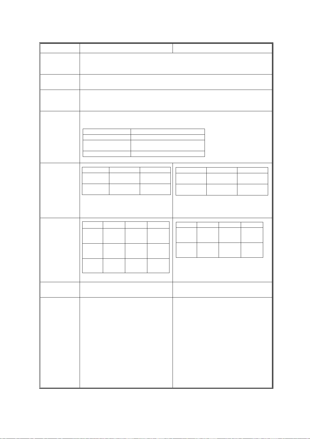
1.2.1 IMAGE GENERATION PROCESS
10
11
9
12
1
2
3
4
5
8
1. Drum Charge
2. Quenching
3. Drum Cleaning
4. PPC (Pre-cleaning Corona)
5. Belt Transfer
6. Paper Transfer
B017V110.WMF
67
7. Paper Separation Corona
8. Belt Cleaning Unit and Lubricant
Application Brush
9. ID Sensor
10. Development
11. Potential Sensor
12. Laser Exposure
1-10
Page 13

28 August, 2000 MECHANISM OVERVIEW
(1) Drum Charge
The charge corona applies a negative charge to the OPC drum and the charge grid
ensures that this charge is even.
- B017/018 -
• A new charge corona cleaner was adopted to keep the charge wire and charge
grid clean. The cleaner starts automatically when the main switch is turned on
and if the fusing temperature is less than 100oC.
(2) Quenching
After cleaning, the OPC is fully exposed to light from an array of red LEDs, which
quench the residual charge on the OPC drum in preparation for the next copy
cycle.
(3) Drum Cleaning
The cleaning brush increases drum cleaning efficiency by applying lubricant to the
OPC drum. The cleaning blade scrapes the residual toner off the OPC drum.
Overall
Information
(4) PCC (Pre-cleaning Corona)
The PCC lowers the charge on the photoconductor drum by applying AC and
negative DC to improve the efficacy of the cleaning brush.
(5) Belt Transfer
Positive charge applied to the back of the transfer belt transfers the toner image on
the OPC drum to the transfer belt.
- B017/018 -
• The electrical resistance of the belt varies from belt to belt and directly influences
the image transfer belt bias. To optimize the image transfer belt bias a Current
Feedback System was adopted to correct the current fluctuation caused by the
variation of the electrical resistance on the belt.
• Another solenoid was added to the image transfer belt unit to keep the belt away
from the drum between copy jobs. This helps prevent drum fatigue from residual
voltage on the belt.
1-11
Page 14

MECHANISM OVERVIEW 28 August, 2000
(6) Paper Transfer
The negatively charged toner image is transferred to the paper by giving a positive
charge to the back of the paper while the paper and transfer belt are held in close
contact.
- B017/018 -
• A brush was added to the image transfer belt unit to help push the belt down.
This enables toner on the transfer belt to transfer onto the paper before the
electrical field between the transfer belt and roller affects it. This helps to
decrease the amount of scattered toner on printouts.
(7) Paper Separation Corona
After transfer, the separation corona quenches the negative charge on the paper to
reduce the attraction between the belt and paper. The curvature of the belt causes
the paper to separate from the transfer belt.
(8) Belt Cleaning Unit and Lubricant Application Brush
The brush applies lubricant, which makes it easier for the belt cleaning blade to
scrape excess toner off the transfer belt.
(9) ID Sensor
The ID sensor detects the density of the sensor patches developed on the OPC
drum. The signal from the ID sensor is used for process and toner supply control.
- B017/018 -
• A thermistor has been added to the ID sensor board. The thermistor corrects the
output from the ID sensor depending on the temperature. This supplies more
reliable data for better toner density control.
(10) Development
The latent image on the drum attracts the negatively charged toner. Toner is
preferentially attracted to those places on the drum surface where the laser
reduced the negative charge. The development units for each color are included in
the revolver unit.
- B017/018 -
• A High frequency alternating current is applied to the development bias to
optimize development. This improves the quality of grainy images.
1-12
Page 15

28 August, 2000 MECHANISM OVERVIEW
(11) Potential Sensor
The potential sensor detects the electrical potential (the strength of the electric
field) on the photoconductor dru m for process contr ol .
(12) Laser Exposure
The polygon mirror reflects the laser beam emitted from the laser diode and
projects it onto the drum through the f-theta lens, drum mirror, and toner shield
glass. The intensity of the laser output varies in correspondence with the image
data. This process creates the latent image on the drum.
- B017/018 -
• The laser power was adjusted to achieve uniform side-to-side laser power. This
causes the laser power to be applied evenly across the drum surface.
• Pulse positioning control was adopted to make the image appear smoother.
Overall
Information
1-13
Page 16
MAJOR UNIT LAYOUT AND PAPER FEED PATH 28 August, 2000
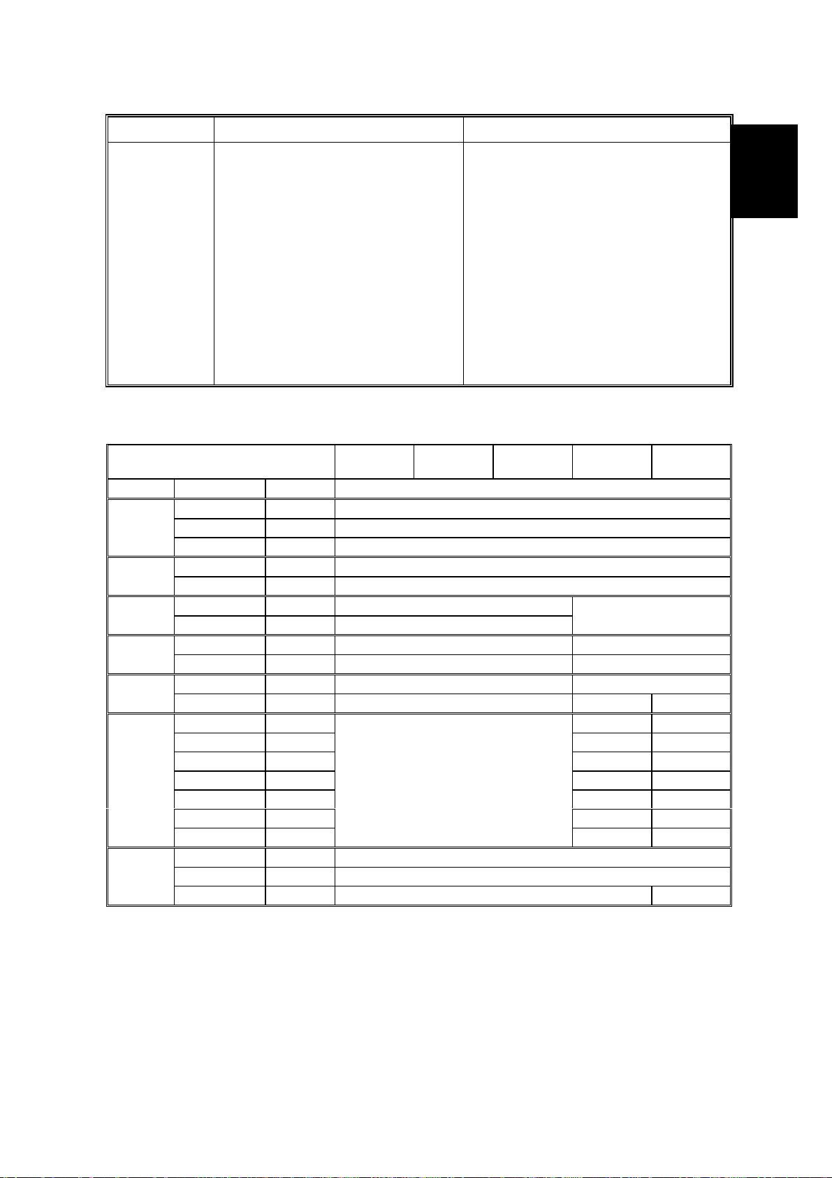
1.3 MAJOR UNIT LAYOUT AND PAPER FEED PATH
1
2
3
8
7
4
6
B017V109.WMF
(1) Scanner
• 400 dpi, 10-bit scanning in both main and sub-scan directions
(A258/259/260)
• 600 dpi, 10-bit scanning in both main and sub-scan directions (B017/018)
• 3-line CCD
• Halogen exposure lamp
• 5-phase stepper motor drive
• Dual-side continuous scan (A4) support (in continuous copy mode)
• One scan copy in mono-toner color multi-copies (B017/18)
(2) Operation panel (A259, A260, and B017)
• 10.4-inch (640 x 480) color LCD (8-bit) touch-panel
• An additional operation panel is installed when the printer controller is
installed.
5
1-14
Page 17

28 August, 2000 MAJOR UNIT LAYOUT AND PAPER FEED PATH
(3) Laser unit
• Optics: 6-sided polygon mirror + 2 f-theta lenses + BTL
• Polygon mirror motor (24,5 67 rpm) with oil bearing (A258/259/260)
• Polygon mirror motor (36,8 50 rpm) with oil bearing (B017/018)
• 400 dpi (8 bits per pixel for each color) in copy mode
600 dpi (8 bits per pixel for each color) in printer mode (A258/259/260)
• 600 dpi (8 bits per pixel for each color) in both the copy and printer modes
(B017/018)
• Modulation: PM + PWM
• Laser power correction (B017/018)
• Image rotation feature (B017/018)
(4) Transfer belt
• Transfer belt: Always in contact with the drum (A258/259/260)
• Transfer belt: In contact with drum during copy process (B017/018)
• Belt transfer: Indirect application of voltage with a roller
• Paper transfer: Roller transfer
• Registration: Synchronization by the transfer belt H.P. sensor
• Drive: Synchronized with the drum (same motor)
• Separation: Curvature separation + corona unit
• Transfer cycle: 1 belt rotation/A4, 2 rotations/A3
• Belt cleaning: Counter blade
• Lubrication: Brush roller with lubricant bar
• Bias control: Current feedback system (B107/018)
Overall
Information
(5) Paper feed/transport system
• Paper feed (A258/B018)
Front loading 500 sheets, 1-layer tray + by-pass feed
• Transport: Transport belt + fan
• Duplexing: Duplex unit installed as a standard component (A259/A260/B017)
• Paper tray (optional): Holds 500 sheets x 2 trays or 500 sheets x 3 trays.
(6) Fusing and paper exit
• Fusing: Silicone roller fusing (A258/259/260)
Fusing: Silicone belt and roller fusing (B017/018)
• Oil application method: Double roller system
• Cleaning: Cleaning rollers (for hot and pressure rollers) (A258/259/260)
Europe/Asia: Cleaning roller for hot roller, cleaning blade for pressure roller
• Cleaning: Tension roller for fusing belt, blade and pad for pressure roller.
(B017/018)
• OHP/thick paper speed change
1-15
Page 18

MAJOR UNIT LAYOUT AND PAPER FEED PATH 28 August, 2000
(7) Development and toner supply
• Development: Two-component magnetic brush d evelopment
• Development switching: Revol ver system
• Image density control: ID sensor + process control
• Toner supply: Screw-in bottle (220 g)
• Toner supply unit: Front of developer unit (rotation type)
(8) Drum unit
• The drum unit contains the photoconductor drum, charge corona unit, and
cleaning unit.
• Charge corona unit: Single-wire scorotron
• Quenching lamp: LED array
• Drive: Synchronized with the transfer belt (DC brushless motor + flywheel)
• Potential sensor included
1-16
Page 19
28 August, 2000 PARTS LAYOUT
1.4 PARTS LAYOUT
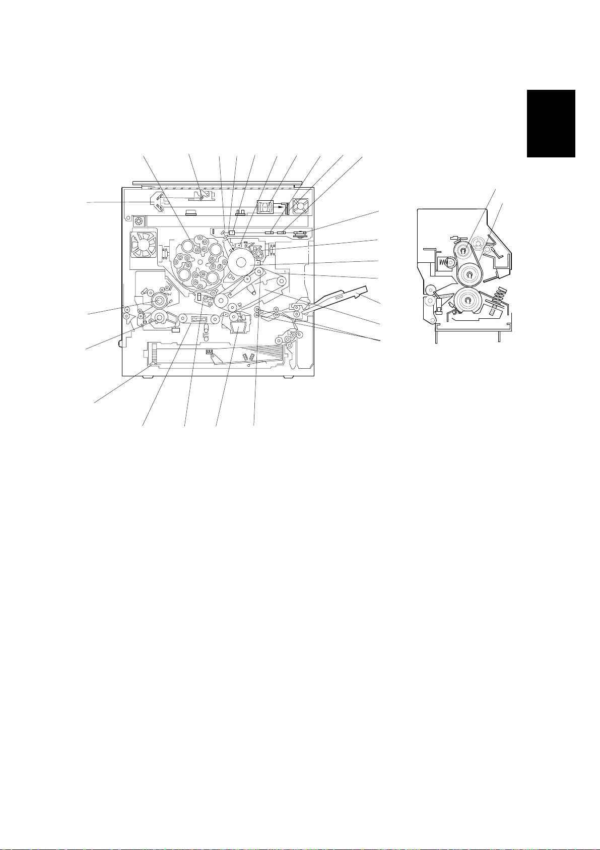
1.4.1 MECHANICAL COMPONENT LAYOUT
56789111314
4
3
1210
27
26
15
16
17
18
19
20
Overall
Information
2
1
22232425
1. Paper Tray (A258/B018)/Duplex Tray
(A259/A260/B017)
2. Pressure Roller
3. Hot Roller
4. 2nd Scanner
5. Revolver Develop m ent Unit
6. 1st Scanner
7. Drum Mirror
8. Toner Shield Glass
9. BTL (Barrel Torroidal Lens)
10. Charge Corona Unit
11. Scanner Lens
12. 2nd F-theta Lens
13. CCD Board
21
B017V113.WMF
B017V108.WMF
14. 1st F-theta Lens
15. Polygon Mirror
16. Drum Cleaning Unit
17. OPC Drum
18. Image Transfer Belt (ITB)
19. By-pass Feed Table
20. Image Transfer Belt Un it
21. Registration Roller
22. Transfer Belt Bias Rol ler
23. Paper Transfer Unit
24. Belt Cleaning Unit
25. Transport Belt
26. Fusing Belt (B017/018)
27. Heat Roller (B017/018)
1-17
Page 20
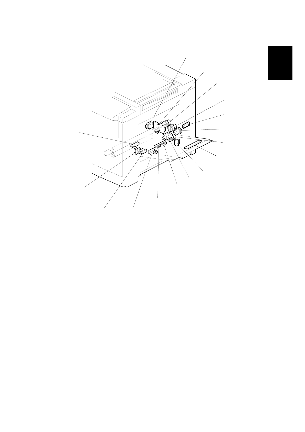
PARTS LAYOUT 28 August, 2000
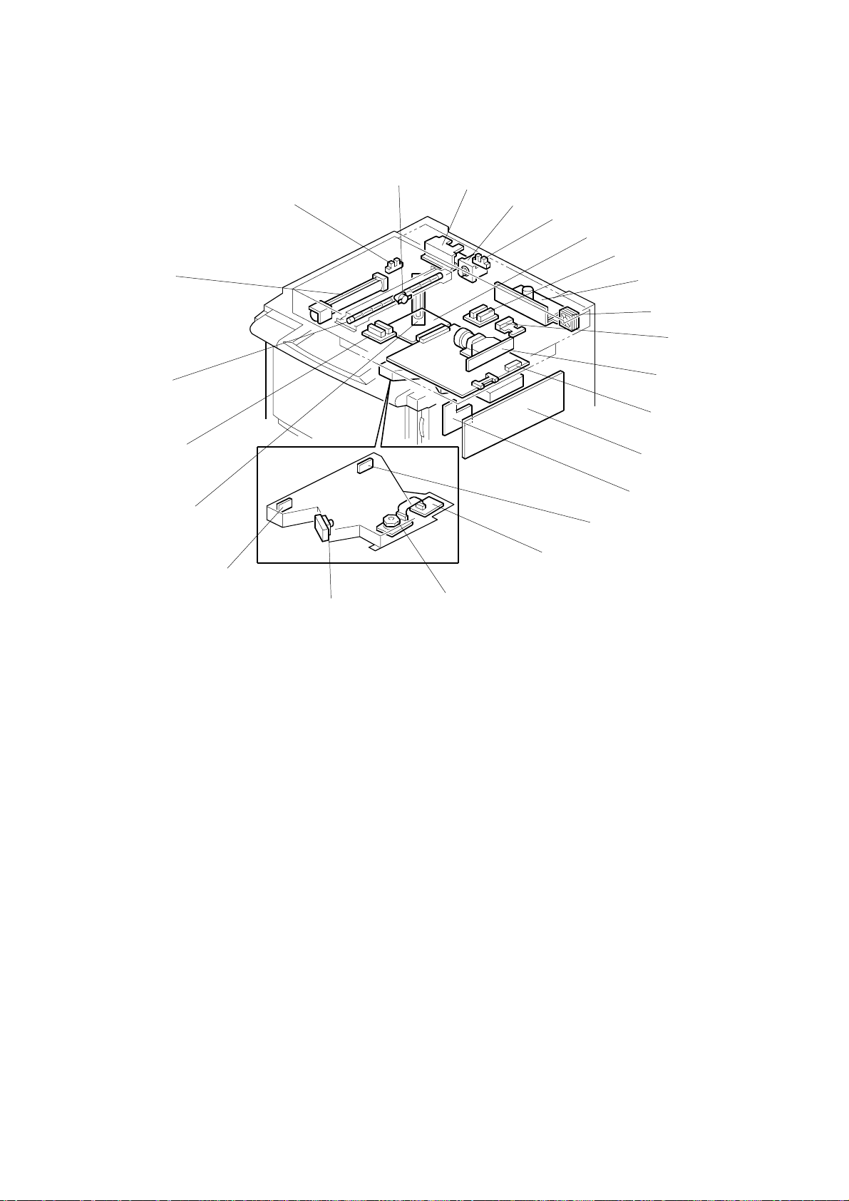
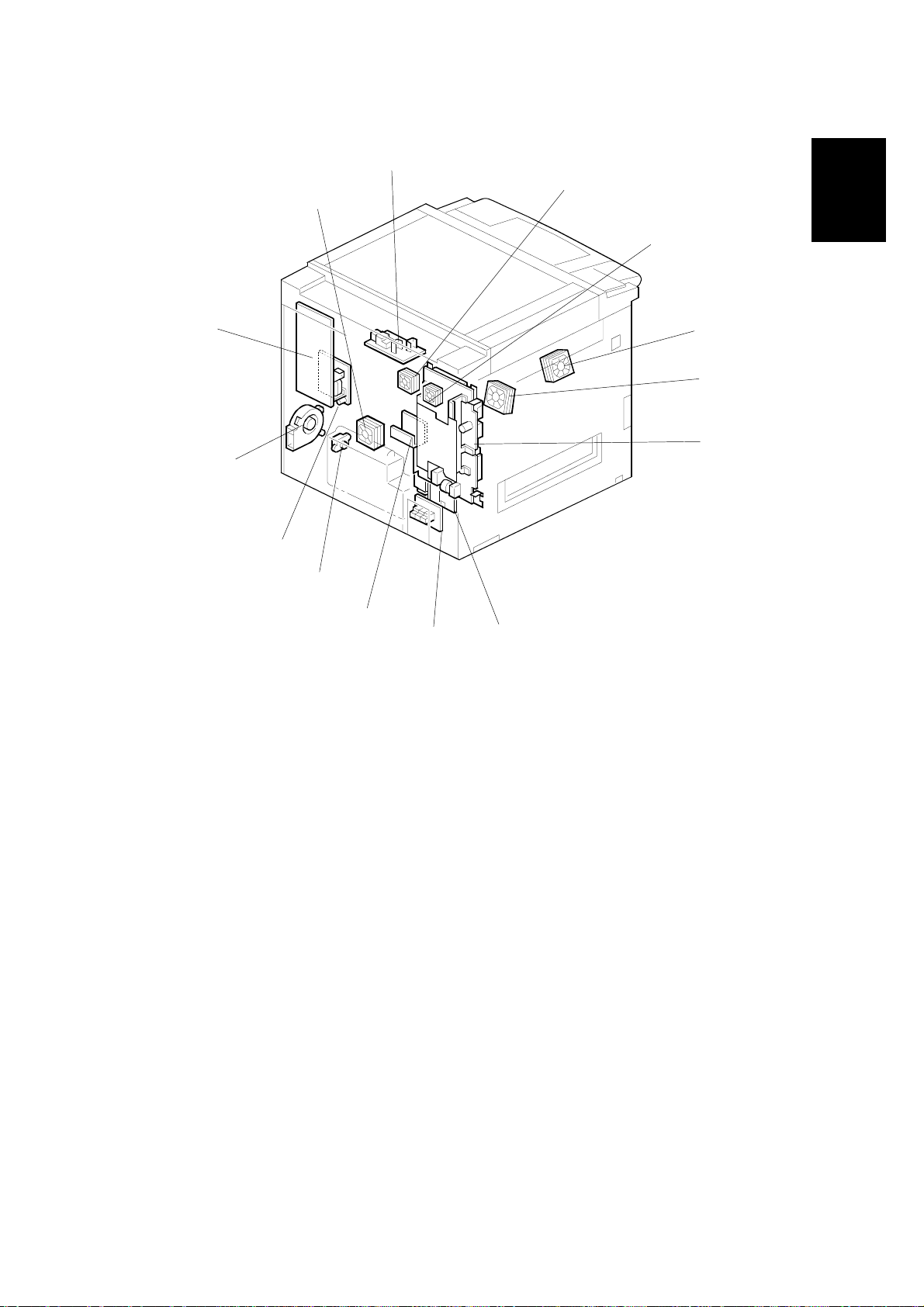
1.4.2 ELECTRICAL COMPONENT LAYOUT
- A258/259/260 -
20
19
18
17
16
21
15
22
1
2
3
4
5
6
7
23
8
9
10
11
12
13
B017V101.WMF
14
1. Scanner Motor Drive Board
2. Scanner Motor
3. Platen Cover Position Sensor
4. IDU Board
5. Original Length Sensor
6. Lamp Regulator
7. Scanner Exhaust Fan
8. CCD Board (SBU)
9. Scanner IPU Board
10. Main Control Board
11. LD (Laser Diode) Main Control Board
12. Laser Synchronizing Detector
Board 2
Diagram 1
13. Polygon Mirror Motor Drive Board
14. Polygon Mirror Motor
15. LD (Laser Diode) Drive Board
16. Laser Synchronizing Detector
Board 1
17. Optics Anti-condensation Heat er
18. Original Width Sensor
19. Exposure Lamp
20. Optics Cooling Fan
21. Scanner H.P. Sensor
22. Exposure Lamp Thermostat
23. Original Length Sensor-Sub
1-18
Page 21
28 August, 2000 PARTS LAYOUT
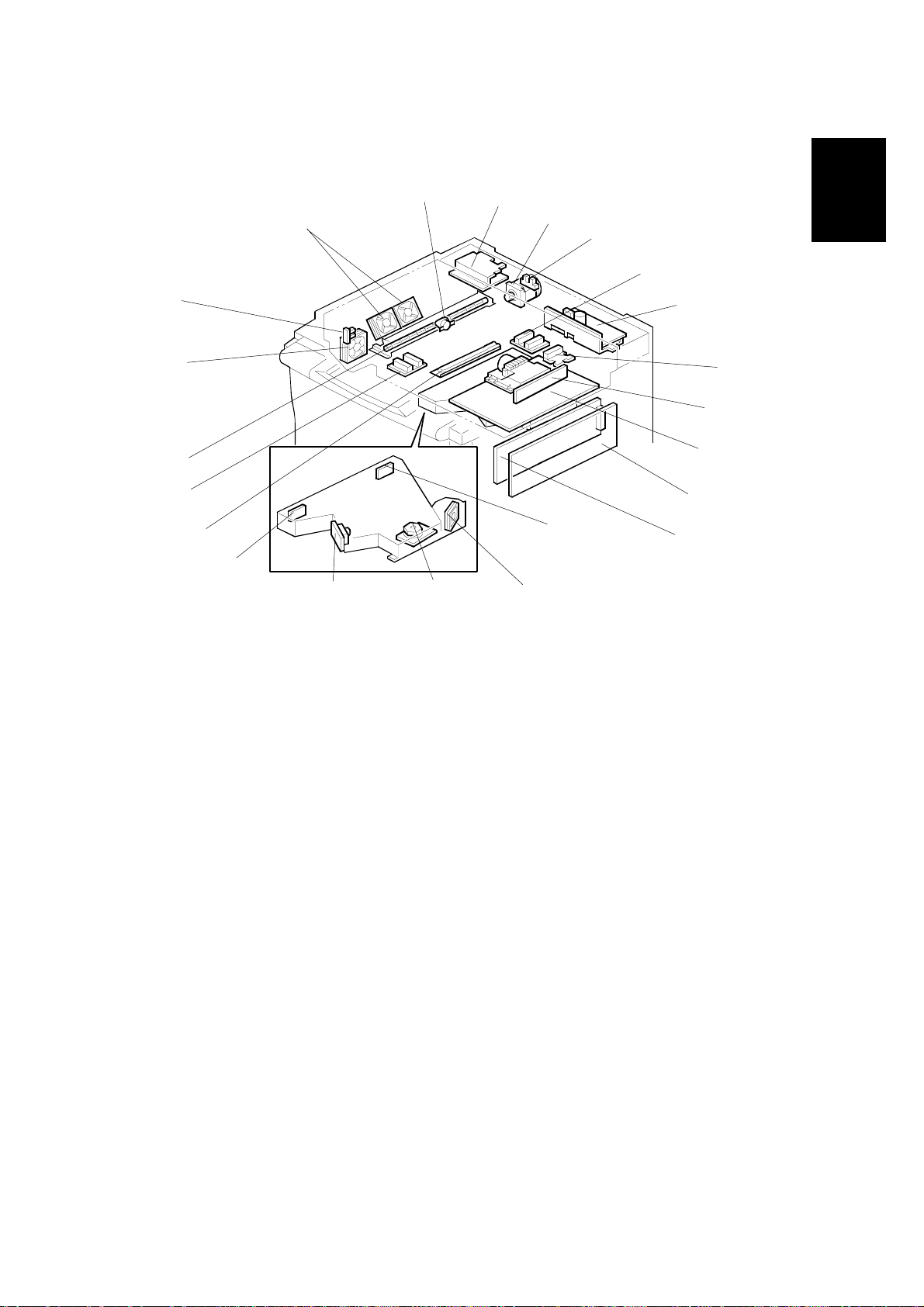
1.4.3 ELECTRICAL COMPONENT LAYOUT
- B017/018 -
21
24
19
18
17
16
20
15
22
14
1
2
3
Overall
Information
5
6
23
8
9
10
25
12
B017V117.WMF
11
1. Scanner Motor Drive Board
2. Scanner Motor
3. Platen Cover Position Sensor
4. Blank
5. Original Length Sensor
6. Lamp Regulator
7. Blank
8. CCD Board (SBU)
9. Scanner IPU Board
10. Main Control Board
11. LD (Laser Diode) Main Control Board
12. Laser Synchronizing Detector
Board 2
13. Blank
Diagram 1
14. Polygon Mirror Motor
15. LD (Laser Diode) Drive Board
16. Laser Synchronizing Detector
Board 1
17. Optics Anti-condensation Heat er
18. Original Width Sensor
19. Exposure Lamp
20. Optics Cooling Fans
21. Scanner H.P. Sensor
22. Exposure Lamp Thermostat
23. Original Length Sensor-Sub
24. IPU Cooling Fan
25. Polygon Mirror Motor Cooling Fan
1-19
Page 22
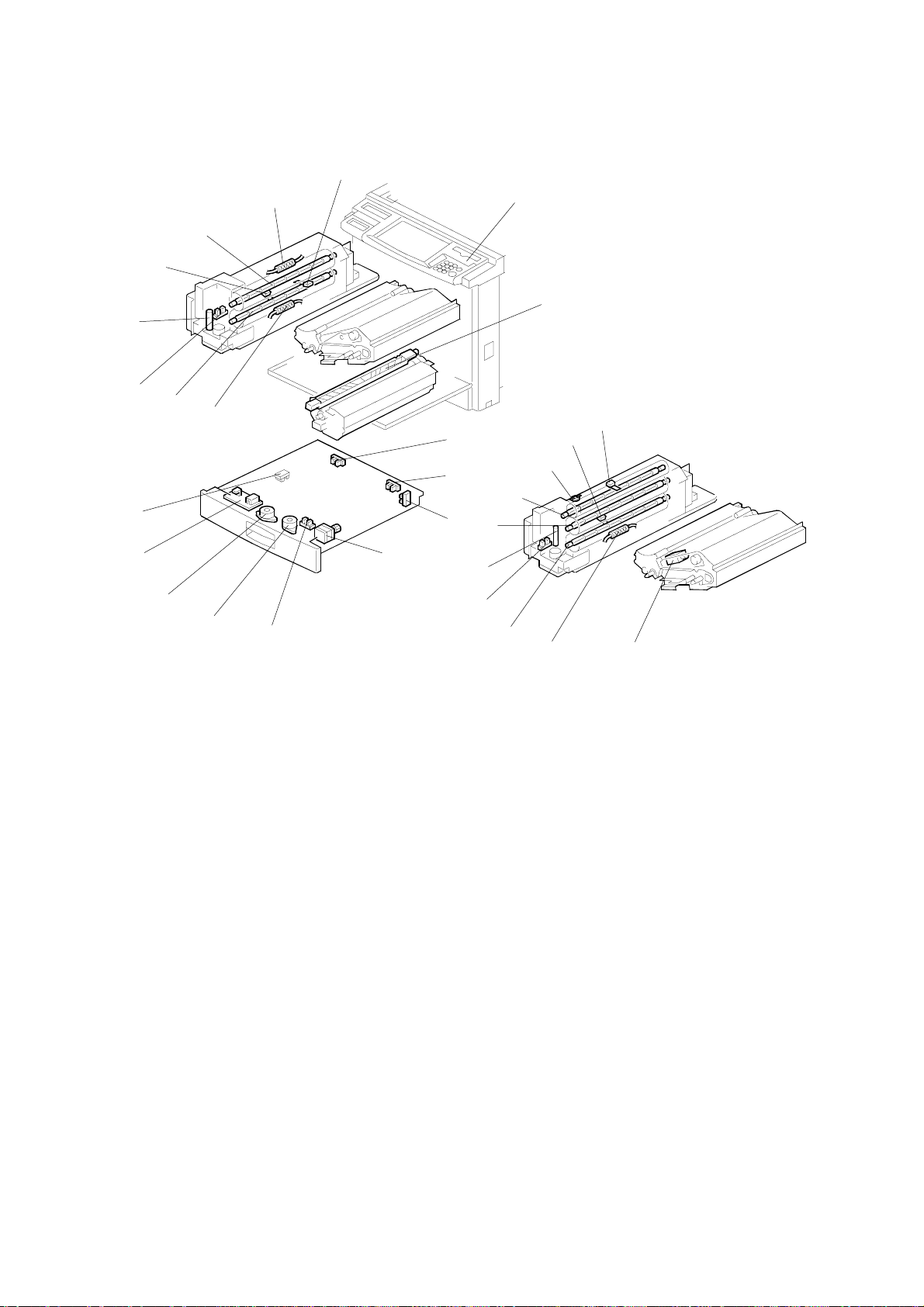
PARTS LAYOUT 28 August, 2000
14
13
12
2
3
1
4
5
6
7
11
B017V102.WMF
10
9
8
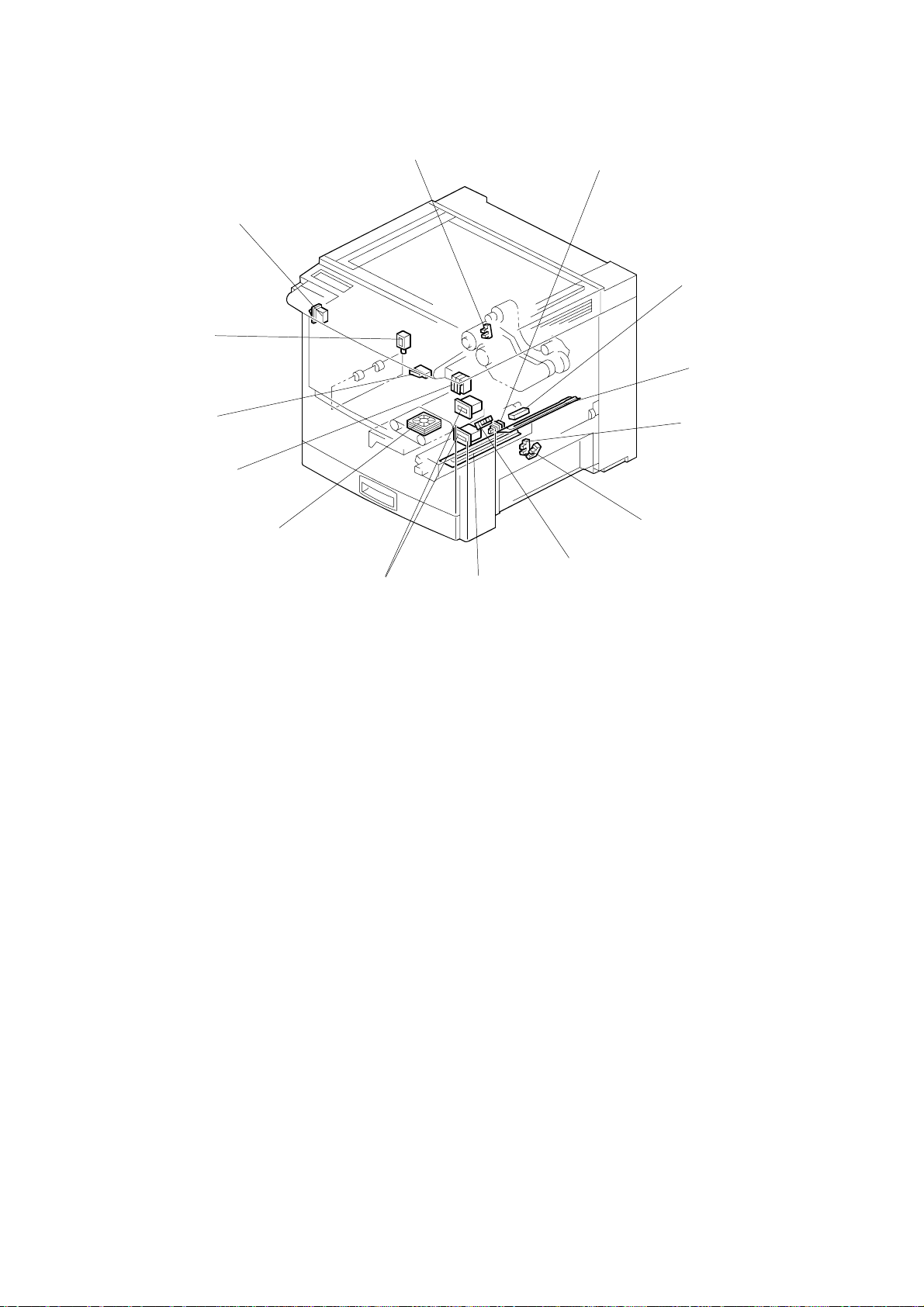
1. Main Power Switch
2. Belt Cleaning H.P. Sensor
3. Paper Tray Detector Switch
4. Transfer Belt Home Position Sensor
5. Transfer Belt Heater
6. Paper Height Sensor-1
7. Paper Height Sensor-2
8. Paper Transfer H.P. Sensor
Diagram 2
9. Paper Transfer Unit Heater
10. Counters
11. Transport Fan
12. Front Door Switch
13. Paper Exit Door Switch
(A259/A260/B017)
14. Junction Gate Solenoid
(A259/A260/B017)
1-20
Page 23
28 August, 2000 PARTS LAYOUT
1
15
14
13
12
11
9
10
B017V103.WMF
2
Overall
Information
3
4
16
5
6
7
8
1. Paper Transfer Positioning Clutch
2. Paper Feed Motor
3. Registration Clutch
4. Relay Clutch
5. By-pass Feed Clutch
6. Paper Feed Clutch
7. By-pass Paper Width Detection Board
8. Vertical Transport Switch
Diagram 3
9. By-pass Pick-up Solenoid
10. Upper Limit Sensor
11. Paper End Sensor
12. Relay Sensor
13. By-pass Paper End Sensor
14. By-pass Feed Table Switch
15. Registration Sensor
16. Temperature and Humidity Sensor
1-21
Page 24
PARTS LAYOUT 28 August, 2000
10
9
1
8
7
2
6
5
4
3
11
10
22
B017/018
21
12
20
19
13
8
18
17
16
B017V104.WMF
15
14
Diagram 4
1. Operation Panel
2. Paper Separation Corona Unit
3. Pressure Roller Thermofuse
4. Pressure Roller Fusing Lamp
5. Paper Exit Sensor
6. Oil End Sensor
7. Hot Roller Thermistor (A258/259/260)
8. Hot Roller Fusing Lamp
9. Hot Roller Thermofuse (A258/259/260)
6
5
B017V114.WMF
4
3
12. Duplex Turn Sensor
13. Duplex Paper End Sensor
14. Duplex Feed Motor
15. Side Fence Jogger HP Sensor
16. Duplex Side Fence Jogger Mot or
17. Duplex End Fence Jogger Motor
18. Duplex Control Board
19. End Fence Jogger HP Sensor
20. Heat Roller Fusing Lamp (B017/018)
23
10. Pressure Roller Thermistor
11. Duplex Entrance Sens or
21. Heat Roller Thermostat (B017/018)
22. Heat Roller Thermistor (B017/018)
23. Image Transfer Belt Re lease Solenoid
(B017/018)
1-22
Page 25
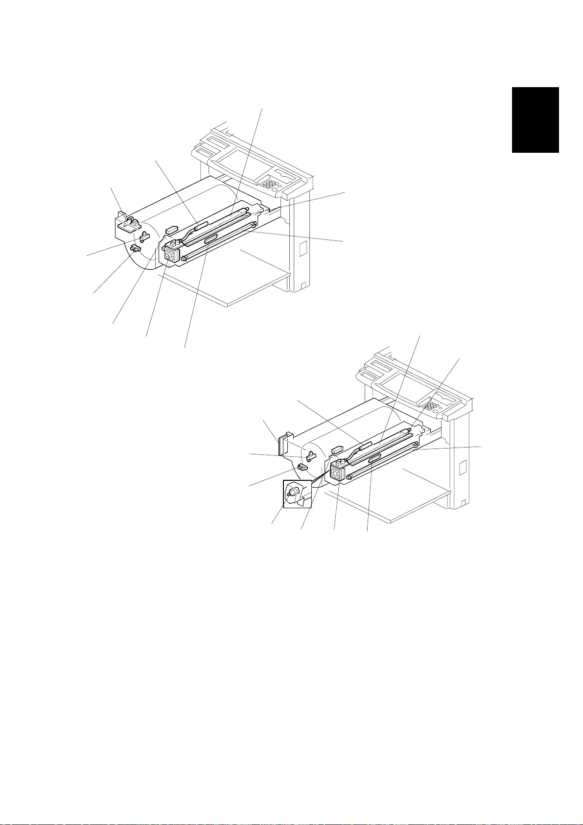
28 August, 2000 PARTS LAYOUT
1
10
Overall
Information
9
2
3
8
7
6
5
4
B017V105.WMF
1
2
10
9
8
3
1. Charge Corona Unit
2. Quenching Lamp
3. PCC (Pre-cleaning Cor ona)
4. ID Sensor
5. Charge Corona Fan
6. Toner Cartridge Sensor
7
11
6
Diagram 5
7. Revolver H.P. Sensor
8. Toner End Sensor
9. High Voltage Supply Board: B
10. Potential Sensor
11. Charge Corona Cleaner Motor
1-23
5
(B017/018)
4
B017V115.WMF
Page 26
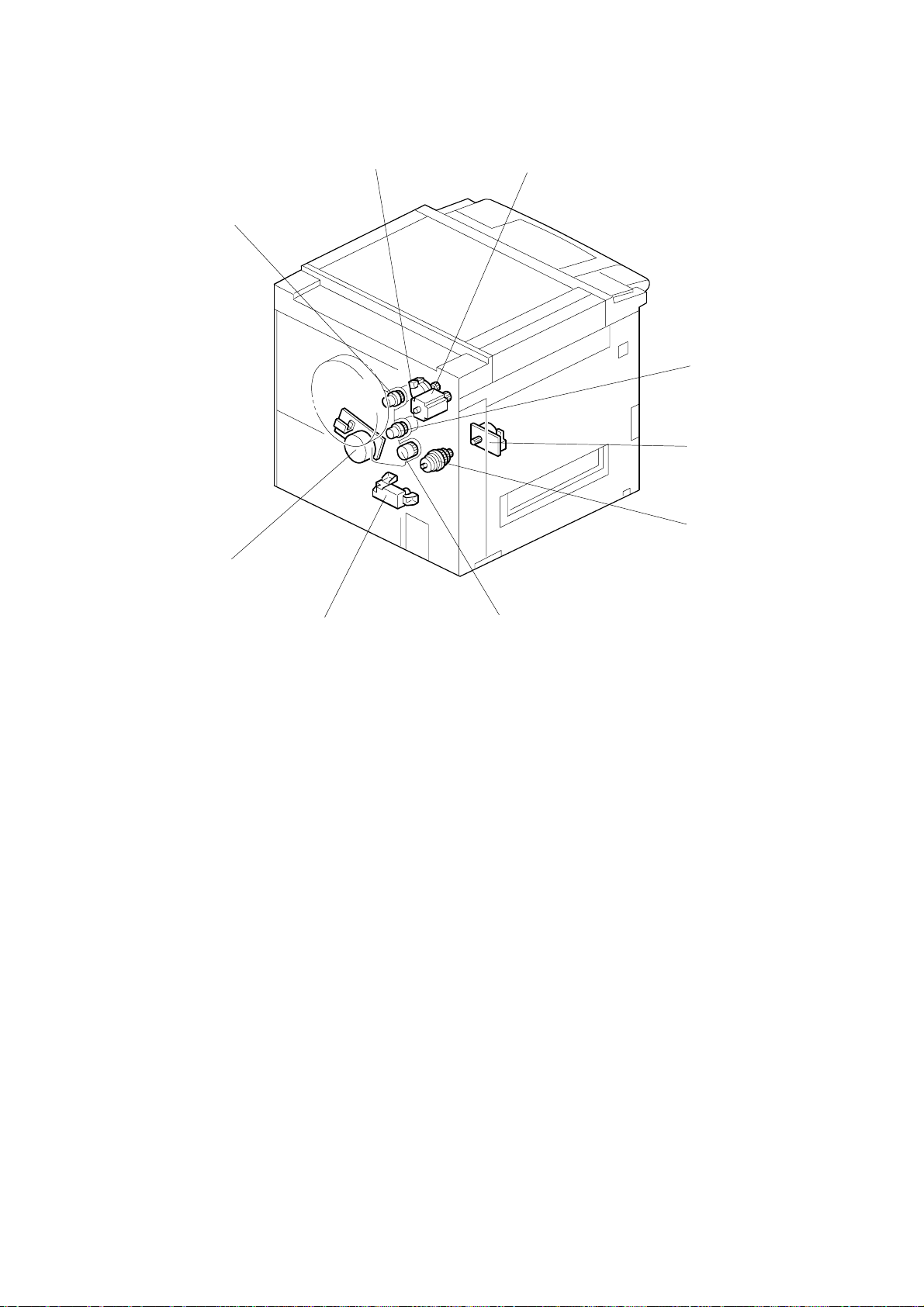
PARTS LAYOUT 28 August, 2000
2
3
1
4
5
6
9
B017V106.WMF
1. Development Clutch
2. Toner Supply Motor
3. Revolver Motor
4. Belt Lubricant Clutch
5. Fusing Motor
8
7
Diagram 6
6. Fusing Clutch
7. Belt Cleaning Clutch
8. Tray Lift Motor
9. Drum Motor
1-24
Page 27
28 August, 2000 PARTS LAYOUT
1
2
13
12
Overall
Information
11
10
9
8
7
1. High Voltage Supply Board: C, G
2. Rear Upper Cooling Fan Motor
14
3
4
B017V107.WMF
56
Diagram 7
8. Used Toner Sensor
9. High Voltage Supply Board: T1, PCC
3. Fusing Unit Fan Motor
4. PSU (Power Supply Unit)
5. High Voltage Supply Board: T2, D
6. CSS/Bank Interface Board
7. Revolver Motor Drive Board
10. Main Exhaust Fan Motor
11. I/O (Input/Output) Control Board
12. PSU Fan Motor
13. Rear Lower Cooling Fan
14. Development Cooling Fan (B017/018)
1-25
Page 28
PARTS LAYOUT 28 August, 2000
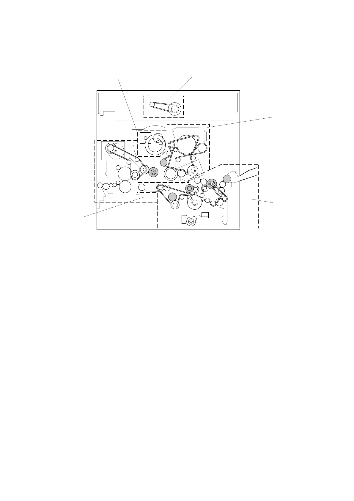
1.4.4 DRIVE LAYOUT
5
1
2
3
4
B017V111.WMF
Five motors drive the mechanical components for this machine. The drive sections
driven by these five motors are listed below.
1. Scanner Drive
2. Development/Drum/Transfer Belt
Drive
3. Paper Feed/Registration/Paper
Transfer/Transport Belt Drive
4. Fusing Unit/Paper Exit Drive
5. Revolver Drive
1-26
Page 29
28 August, 2000 PARTS LAYOUT
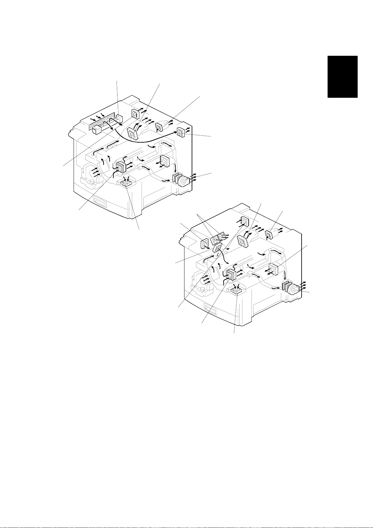
1.4.5 AIR FLOW
A258/259/260
8
7
B017V112.WMF
1
2
Overall
Information
3
4
5
2
1
3
9
6
10
1. Optics Cooling Fan
2. Fusing Unit Fan
3. Rear Upper Cooling Fan
4. Scanner Exhaust Fan
(A258/259/260)
5. Main Exhaust Fan
6. Transport Fan
11
5
8
B017/018
7
6
B017V116.WMF
7. Charge Corona Fan
8. PSU Fan
9. IPU cooling fan (B017/018)
10. Rear lower cooling fan
11. Development cooling fan (B017/018)
1-27
Page 30

PARTS LAYOUT 28 August, 2000
1.4.6 ELECTRICAL COMPONENT DESCRIPTIONS
Printed Circuit Boards
Symbol Name Function
PCB1 PSU Supplies AC and DC power. 7-4 K4 G3
PCB2
PCB3
PCB4
PCB5
PCB6
PCB7
PCB8
PCB9
PCB10
PCB11 Main control Controls the printer sequence. 1-10 J12 E10
PCB12
PCB13
PCB14 Revolver motor drive Controls the revolver motor. 7-7 F5 D4
PCB15
PCB16 LD drive Drives the laser diode. 1-15 O17 J9
PCB17
Lamp regulator Supplies AC power to the
exposure lamp.
SBU
Scanner IPU Converts the RGB image signal
Scanner motor drive
I/O control Interfaces the sensors, clutches,
High voltage supply:
C, G
High voltage supply:
T1, PCC
High voltage supply:
T2, D
High voltage supply:BSupplies power to the
Laser synchronizing
detector 1
Laser synchronizing
detector 2
Interface: CSS/Bank Connects to the CSS unit and
LD main control
Converts the light reflected from
the original into video signals.
from the CCD to a CMYK signal
and sends it to the LD main
control board.
Supplies DC power to the
scanner motor.
solenoids, and motors in the
printer module with the main
control board.
Supplies power to the charge
corona wire and grid.
Supplies power to the transfer
belt and pre-cleaning corona
unit.
Supplies power to the paper
transfer bias roller and paper
separation corona unit.
development rollers.
Detects laser main scan
synchronization while the latent
image is being written to the
drum.
Detects laser main scan
synchronization while the latent
image is being written to the
drum.
optional paper tray unit.
Controls the laser power, main
scan synchronizing sensors, and
process control gamma
correction.
Rotates scanned image
(B017/018)
Analyzes images for anticounterfeiting. (B017/018)
Index-
1-6 O7 J6
1-8 J9 G6
1-9 L8 H7
1-1 M7 H4
7-11 D14 C7
7-1 A14 A10
7-9 A2 A4
7-5 A1 A3
5-9 A3 A1
1-16 O15 J9
1-12 O15 J10
7-6 J9 F6
1-11 M16 H10
No
A258/259/
Location
260
B017/018
1-28
Page 31

28 August, 2000 PARTS LAYOUT
Location
260
Symbol Name Function
PCB18
By-pass paper width
detection
Detects the paper width on the
by-pass feed table.
Index-
No
A258/259/
3-7 A10 A5
PCB19 Operation panel Used to operate the copier. 4-1 H19
F20
(A259/A260
copiers only)
PCB20
PCB21
PCB22
PCB23
PCB24
Duplex control Controls the duplex unit.
IDU
Analyzes images for anticounterfeiting. (A258/259/260)
Polygon mirror motor
drive
Temperature and
humidity sensor
Controls the polygon mirror
motor. (A258/259/260)
Detects the ambient temperature
and humidity.
Header relay Supplies the power to the
heaters
4-18
1-4 M14 -
1-13 O15 -
3-16 E19 D11
-- H1
Motors
Symbol Name Function
Index-
No
A258/259/
M1 Scanner Drives the scanner. 1-2 M6 H4
M2
Polygon mirror Drives the polygon mirror (laser
unit).
1-14 O15 H8
M3 Revolver drive Rotates the revolver unit. 6-3 G5 E4
Drives the paper feed roller in
the duplex unit.
Drives the duplex unit side
fences.
Drives the duplex unit end
fences.
4-14
4-16
4-17
(A259/A260
copiers only)
(A259/A260
copiers only)
(A259/A260
copiers only)
M4
M5
M6
Duplex feed motor
Duplex Side fence
jogger
Duplex End fence
jogger
M7 Paper feed Drives the paper feed unit. 3-2 A12 A6
Tray lift Lifts the tray bottom plate.
M8
6-8
(A258 model
M9 Toner supply Supplies toner. 6-2 A7 A3
Drum Drives the drum, the
M10
development unit currently at the
development position, and the
6-9 A19 A9
transfer belt.
M11
M12
Fusing Drives the transport and fusing
units.
Charge corona
cleaner
Drives the charge corona
cleaner
6-5 E8 A10
5-11 - A2
Location
260
G20
G21
G21
A12
only)
B017/018
Overall
Information
D12
B017/018
E12
(B017
models only)
E12
(B017
models only)
E13
(B017
models only)
A7
(B018
models only)
1-29
Page 32

PARTS LAYOUT 28 August, 2000
Fan Motors
Symbo
l
FM1
Name Function
Transport
Attracts copy paper to the
transport belt.
Index-
No
A258/259/
2-11 A11 A6
Location
260
B017/018
FM2 Optics cooling Cools the scanner unit 1-20 O14 FM3 Charge corona Cools the charge corona unit. 5-5 A6 A3
FM4 Scanner exhaust Cools the scanner unit. 1-7 P7 FM5 Fusing unit Cools the fusing unit. 7-3 E1 D4
Main exhaust Sucks air from the charge and
FM6
transfer areas out of the
7-10 A17 A5
machine.
Rear cooling unit
(A258/59/60)
FM7
Rear upper cooling
Cools the rear section of the
copier.
7-2 E10 D3
(B017/018)
FM8 PSU Cools the PSU. 7-12 A7 A11
Rear lower cooling Cools the rear section of the
FM9
copier.
7-13 D2
FM10 Polygon mirror motor Cools the polygon mirror motor 1-25 - D6
FM11 Optics cooling 0 1-20 - J7
FM12 Optics cooling 1
Cools the scanner unit.
1-20 - J7
FM13 IPU cooling Cools the IPU section. 1-24 - J7
FM14 Development cooling Cools the development section. 7-14 - J7
Sensors
Symbol Name Function
Detects the presence or
absence of toner in a
cartridge.
Detects the presence or
absence of toner cartridges.
Detects if the revolver is at
the home position.
drum surface.
on the developed ID sensor
patch on the drum.
unit is at the home position.
Detects if there is paper on
the by-pass feed table.
position of the tray bottom
plate.
relay section.
S1
S2
S3
S4
S5
S6
S7
S8
S9
Toner end
Toner cartridge
Revolver H.P.
Potential Detects the potential of the
ID Detects the density of toner
Belt cleaning H.P. Detects if the belt cleaning
By-pass feed paper
end
Upper limit Detects the upper limit
Relay Detects paper jams at the
Index-
No
A258/259/
Location
260
B017/018
5-8 A4 A1
5-6 A4 A1
5-7 A4 A2
5-10 A5 A2
5-4 A5 A2
2-2 A8 A11
3-13 A8 A5
A13
3-10
(A258 model
only)
(B018 model
A13
3-12
(A258 model
only)
(B018 model
A7
only
A7
only)
1-30
Page 33

28 August, 2000 PARTS LAYOUT
Symbol Name Function
Tray paper end
S10
Detects if there is paper in
the paper feed tray.
Relay Detects a paper jam at the
S11
S12
S13
S14
Used toner Detects if the used toner tank
Paper transfer H.P. Detects if the paper transfer
Paper height 1
relay section
is full.
unit is at the home position.
Detects the amount of paper
in the tray.
Paper height 2 Detects the amount of paper
S15
S16
S17
S18
S19
S20
S21
S22
S23
S24
S25
Transfer belt H.P. Detects the mark on the
Registration H.P. Detects paper jams at the
Paper exit Detects paper jams at the
Oil end
Original length
Platen cover position Detects if the platen cover is
Original length -sub Detects the length of the
Scanner H.P. Detects the scanner home
Original width Detects the width of the
Side fence jogger HP
in the tray.
transfer belt.
registration section.
paper exit.
Detects if there is silicone oil
in that tank.
Detects the length of the
original.
open or closed.
original
position.
original.
Detects the home position of
the duplex unit side fence.
End fence jogger HP Detects the home position of
S26
the duplex unit end fence.
Duplex paper end Detects if there is paper in
S27
the duplex unit.
Duplex entrance Detects when copy paper
S28
Duplex turn
S29
comes into the duplex uni t.
Detects when copy paper is
being reversed in the duplex
unit.
Index-
No
A258/259/
Location
260
B017/018
G13
3-11
(A258 model
only)
(B018 model
A14
3-12
(A259/A260
models only)
7-8 A15 A4
2-8 A15 A4
A16
2-6
(A258 model
only)
(B018 model
A16
2-7
(A258 model
only)
(B018 model
2-4 A18 A9
3-15 A19 A9
4-5 F1 D1
4-6 G1 E1
1-5 N7 J5
1-3 O7 J5
1-23 P7 I4
1-21 P14 J6
1-18 P14 J6
G22
4-15
(A259/A260
models only)
(B017 model
G22
4-19
(A259/A260
models only)
(B017 model
G22
4-13
(A259/A260
models only)
(B017 model
G23
4-11
(A259/A260
models only)
(B017 model
G23
4-12
(A259/A260
models only)
(B017 model
A7
only
A7
A8
only
A8
only
E13
only
E13
only
E13
only
E13
only
E13
only
Overall
Information
1-31
Page 34

PARTS LAYOUT 28 August, 2000
Switches
Symbol
s
SW1
SW2
SW3
SW4
SW5
SW6
Clutches
Name Function
Main power Turns the copier power on
or off.
Front door
Cuts the DC line to the high
voltage supply board when
the front door is open.
Paper exit door Det ects if the paper exit
door is open or closed.
By-pass feed table Detects if the by-pass feed
table is open or closed.
Paper tray detector Detects the presence or
absence of a paper tray.
Vertical transport
Detects if the vertical
transport door is open or
closed.
Index-
No
A258/259/
Location
260
B017/018
2-1 M1 H1
2-12 E11 A11
A7
2-13
(A259/A260
models only)
(B017 model
only)
3-14 A8 A5
A16
2-3
(A258 model
only)
(B018 model
only)
3-8 A17 A4
D2
A7
Symbol
s
CL1
CL2
CL3
CL4
CL5
CL6
CL7
CL8
CL9
Name Function
By-pass feed Transmits drive to the by-
pass feed mechanism.
Paper feed
Transmits drive to the paper
feed mechanism.
Registration T r ansmits drive to the
registration rollers.
Paper transfer
positioning
Transmits drive to the paper
transfer unit.
Development Transmits drive to the
development mechanism.
Relay Transmits drive to the relay
rollers.
Belt cleaning
Transmits drive to the belt
cleaning unit.
Fusing Transmits drive to the
fusing unit.
Belt lubricant Transmits drive to the belt
lubricant mechanism.
Index-
No
A258/259/
Location
260
B017/018
3-5 A9 A5
3-6 A17 A8
3-3 A18 A8
3-1 A11 A6
6-1 E3 D2
3-4 A18 A8
6-7 E2 D1
6-6 E1 D1
6-4 E2 D1
1-32
Page 35

28 August, 2000 PARTS LAYOUT
Solenoids
Symbol
s
SOL1
SOL2
SOL3
By-pass pick-up Lowers the by-pass pick-up
Junction gate
Image t ransfer belt
release
Name Function
roller.
Raises the junction gate for
the duplex tray.
Releases the image
transfer belt from the drum.
Lamps
Symbol Name Function
Hot roller fusing Provides heat to the hot
L1
Pressure roller
L2
fusing
Exposure Applies high intensity light
L3
Quenching Neutralizes any charge
L4
Heat roller fusing Provides heat to the heat
L5
roller.
Provides heat to the
pressure roller.
to the original for exposure.
remaining on the
photoconductor.
roller.
Index-
No
A258/259/
Location
260
B017/018
3-9 A9 A5
A7
2-14
(A259/A260
copiers only)
4-22 - A12
Index-
No
A258/259/
Location
260
B017/018
4-7 H1 E1
4-4 G1 F1
1-19 O5 J5
5-2 A6 A2
4-20 - E1
Overall
Information
D2
Heaters
Symbol Name Function
Paper transfer unit Prevents m oisture from
H1
H2
H3
Transfer belt Used to stabilize the
Optics anticondensation
forming around the paper
transfer unit.
temperature around the
transfer belt.
Prevents moisture from
forming on the optics.
1-33
Index-
No
A258/259/
Location
260
B017/018
2-9 J1 G1
2-5 K1 G1
1-17 L1 G1
Page 36

PARTS LAYOUT 28 August, 2000
Thermistors
Symbol Name Function
TH1
TH2
TH3
Pressure roller Controls the temperature of
the pressure roller.
Hot roller
Heat Roller Controls the temperature of
Controls the temperature of
the hot roller.
the heat roller.
Thermofuses
Symbol Name Function
TF1
TF2
Hot roller Protects the hot roller from
overheating.
Pressure roller
Protects the pressure roller
from overheating.
Thermostat
Index-
4-22 - E1
Index-
A258/259/
No
4-9 F1 D1
4-6 G1 -
A258/259/
No
4-8 H1 4-3 H1 F1
Location
260
Location
260
B017/018
B017/018
Symbol Name Function
Exposure lamp
TS1
Heat roller Prevents the heat roller
TS2
Prevents the exposure lamp
from overheating when it is
on for a long time.
fusing lamp from
overheating when it is on
for a long time.
Counter
Symbol Name Function
Upper mechanical Indicates the total number
CO1
CO2
Lower mechanical
of development cycles
made using the C, M, and Y
development units;
Shows the total number of
black developments.
Index-
1-22 O6 J5
4-21 - E1
Index-
2-10 A9 D6
2-10 A10 D7
No
No
A258/259/
A258/259/
Location
260
Location
260
B017/018
B017/018
1-34
Page 37

28 August, 2000 PROCESS CONTROL
2. DETAILED DESCRIPTION (B017/018)
2.1 PROCESS CONTROL
2.1.1 OVERVIEW
The process control for this machine is almost the same as for the A258/259/260
copiers. The only difference is in the potential values of VD (charge voltage), VL
(laser power), and VB (developme nt bi as) . Thes e pot enti al val ues ar e optimized for
600 dpi processing. By changing the resolution, the density of the pattern used for
process control has been changed. For process control to work properly, these
potential values were changed from the A258/259/260 copier level to their current
potential values for the B017/B018.
2.1.2 POTENTIAL CONTROL
Just like A258/259/260 copiers, there are 4 process control self-checks.
1) Forced process control self-check
2) Initial process control self-check
3) Interval process control self-check
4) Times process control self-check
Detailed
Descriptions
The different points on the process control self-check from A258/259/260 copiers
are as follows.
Initial process control self-check
• The initial process control starts automatically when the power is turned on (or
when the machine returns to stand- by mode fro m sle ep mo de) , but only if the
fusing belt in the fusing unit is less than 550C. This is because the fusing belt
temperature drops faster because the fusing belt is thinner than the hot roller.
TD auto correction (SP3-128)
• During the self-check, the machine automatically adjusts the toner concentration
if the M/A (Mass/Area) of the ID sensor pattern is out of 4.0 +/- 0.05 mg/cm2, in
order to attain proper image density. This mode is executed only when
performing the interval process control self-check. (This was executed only when
performing the initial process control self-check on A258/259/260 copiers.)
2-1
Page 38

DRUM UNIT 28 August, 2000
2.2 DRUM UNIT
2.2.1 DRIVE MECHANISM
The drive mechanism for this machine is the same as for the A258/A259/A260
copiers. However, the drum shaft extends fully from the rear to the front side in
order to prevent the photoconductor gap from fluctuating during drum rotation.
2.2.2 CHARGE CORONA UNIT CLEANER
A charge corona unit cleaner was adopted to prevent the charge corona wire and
charge grid from being contaminated with toner and paper dust.
Drive:
•
Cleaner affixed to screw rod [A].
•
Unit driven by DC motor [B] located at
copier front.
Cleaning:
[D]
•
Grid cleaner pad [C] and charge wire
cleaner pads [D].
•
Home position at copier front.
•
Machine cleans according to conditions
below:
1) When the main switch is turned on.
2) When the fusing temperature is less than 55oC.
3) When forced using an SP mode (SP2-802).
Cleaning Path:
Copier front – Rear end point – Copier front
Only the charge corona grid is cleaned during the traverse from the copier front to
the rear end point (black arrow). Both the charge wire and grid are cleaned during
this traversal from the rear end point to the copier front (white arrow).
Position Detection:
•
No sensor to detect the position of the cleaner.
•
I/O control board detects the current supplied to the motor
• It senses the sudden change in the current value, which occurs when the
cleaner reaches the end point.
• At the turnaround point, the motor reverses.
• If current does not increase within 60 seconds after motor rotation, the I/O control
board detects an open circuit or disconnected condition, stops the motor, and
then displays SC303.
[B]
[A]
B017D597.WMF
[C]
2-2
Page 39

28 August, 2000 SCANNER UNIT
Related SP modes:
1) SP2-802-000: Forced Charger Cleaning
This performs the charge and grid cleaning.
2) SP2-803-001: Auto Cleaning ON/OFF
This specifies the timing when the charger cleaning is performed.
3) SP2-803-002: Development Count
This enables charger cleaning at specified development cycle count
4) SP2-803-003: Operation Time
This specifies the operation time interval.
2.3 SCANNER UNIT
2.3.1 OVERVIEW
• Scanning resolution is 600 dpi.
• Higher resolution improves sharpness, and color and image reproduction
capability.
• A new lens, CCD, and e xposure lamp were added to attain the new 600 dpi
resolution.
• New image rotation feature
• Rotates the scanned image in 90-degree increments and then prints out.
• 80MB of memory is used for the image rotation.
• Stores up to A3/DLT mono-toner color images.
• The copier only makes one scan for the multi copy run in mono-toner
(CMYK) color copy mode.
• The image rotation circuit is in the LD main control board.
Detailed
Descriptions
2-3
Page 40

IMAGE PROCESSING 28 August, 2000
2.4 IMAGE PROCESSING
2.4.1 OVERVIEW
The following features were added to B017/018 copiers or modified from the
A258/259/260 copiers.
Image rotation feature
• Rotates up to A3/DLT full color images.
• Maintains the maximum copy speed by feeding paper sideways.
Laser power correction
• A correction value is applied to the laser power.
• This evenly applies the power across the drum surface, preventing uneven
image density images.
600 dpi resolution
• Improved sharpness and gradation of images.
• New dither patterns in copy mode
• Increased productivity in print mode (Prints images out without slowing down
the process speed for 600 dpi.)
NOTE: On the A258/259/260 copiers, the process speed changes to 2/3 of the
standard speed for 600 dpi.
Dither processing
• Two dither patterns for Text and Photo modes
• Dither pattern size is increased to improve gradation.
Pulse positioning control
• Machine can change the start timing for laser exposure.
• Makes lines appear smoother. (This improves the quality of grainy images.)
2-4
Page 41

28 August, 2000 IMAGE PROCESSING
2.4.2 IMAGE ROTATION
LD Section
Scanner
Section
R/G/B
10 bits
IPU
Section
Y/M/C/K
8 bits
Image rotation
80 MB memory
Dither
processing
Laser
exposure
B017D505.WMF
• The image rotation circuit is located on the LD control board.
• CMYK data processed in the IPU section is sent to the LD control board.
• Image rotation circuit has 80MB memory.
• 64MB to store up to A3/DLT mono toner color image data
• 16MB to store image separation data.
• After the image is rotated in this circuit, dither processing is applied to the image
data and laser exposure begins.
• Since mono-toner color (CMYK) image data can be stored in memory, the
scanner only scans the image once to make multi-copies.
2.4.3 LASER EXPOSURE
Detailed
Descriptions
[B]
[A]
B017D505.WMF
• New polygon mirror motor [ A] to achieve real 600 dpi.
• Rotates at 36,850 rpm.
• The polygon mirror motor cooling fan [B] is beside the optical housing unit
because of this high-speed rotation.
2-5
Page 42

IMAGE PROCESSING 28 August, 2000
2.4.4 LASER POWER CORRECTION
B017D507.PCX
Even if the power from the LD unit is the same from side to side, laser power is not
evenly applied across the drum surface due to the characteristics of the F-theta
and Barrel Torroidal lenses as shown by the curve in the illustration. These
characteristics cause the laser power at the center to be slightly stronger than at
either side. This causes uneven image density on your printout.
Since all scanner units have the same characteristics, a correction curve is applied
to the laser power exposed from the LD unit so that the laser power applied across
the drum surface becomes even. The curved line in the illustration becomes
straight by applying the correction to the laser power.
2.4.5 DITHER PROCESSING
B017D508.WMF
• Two dither patterns for Text and Photo modes.
• In Text mode, dither patterns are made with 2x2 dot units for fine resolution.
• In the Photo mode, dither patterns are made with 3x3 dot units.
• Using the larger unit makes the image appear smoother, improving the quality of
grainy images.
2-6
Page 43

28 August, 2000 IMAGE PROCESSING
2.4.6 PULSE POSITIONING CONTROL
• The location of the active part of the laser signal
can be on either the left or right side of each pixel.
• The positioning of the active part of the laser signal
shifts to the left or right depending on adjacent
pixel values.
• W hen scanning the gray solid image, top righ t, all
active parts locate on the left side of each pixel if
pulse-positioning control is not used.
• Engine capability problems cause these thin lines
to be reproduced improperly.
• The line is not completely straight because image
data was lost. This also causes grainy images.
Detailed
Descriptions
• Pulse positioning control thickens the lines and
reproduces them properly without any image loss.
• This causes the lines to appear smoother. (This
improves the quality of grainy images.)
B017D516.WMF
2-7
Page 44

DEVELOPMENT UNIT 28 August, 2000
2.5 DEVELOPMENT UNIT
2.5.1 OVERVIEW
To optimize image development, a high frequency AC component has been
applied to the development bias. The high frequency AC component improves the
quality of grainy images.
2.5.2 TONER SUPPLY
[B]
[A]
[C]
[E]
[D]
B017D518.WMF
B017D519.WMF
When the revolver unit rotates, small amounts of ton er tend to flow into the
development unit. This causes the toner concentration to increase. To prevent
toner from flowing into the development units, a small window [A] is added to the
development shutter [B] and a magnet [C] is attached on to the toner supply pipe
[D].
A small amount of developer flows back into the toner supply pipe through the
small window on the shutter during the revolver rotation and is caught by the
magnet. The developer caught by the magnet functions as a shield and prevents
toner from flowing into the development unit. When toner is supplied to the
development unit, the supply auger [E] rotates and supplies the proper amount of
toner.
2-8
Page 45

28 August, 2000 IMAGE TRANSFER BELT UNIT
2.6 IMAGE TRANSFER BELT UNIT
2.6.1 OVERVIEW
The image transfer function is the same as the A258/259/260 copiers. The
changes described below were applied to the B017/018 to improve reliability and
image quality.
Image transfer unit positioning
• Changed to maintain the width of the photoconductor gap.
• Changed compression spring position and the shape of the drum stay.
Current feedback system
• Optimized the image transfer bias.
• Automatically corrects the current applied to the belt to apply a constant
optimum transfer bias to the belt.
• This also prevents dark spots.
Touch and release mechanism
• Added a solenoid to the image transfer belt unit.
• Keeps the image transfer belt away from the drum between copy jobs
• Prevents drum fatigue due to residual voltage on the belt.
Paper transfer mechanism
• Added brush to the image transfer belt unit
• Changed the shape of the paper guide of the paper transfer unit.
• Ensures correct paper transfer
• Improves the quality of the toner blaster image.
Detailed
Descriptions
2-9
Page 46

IMAGE TRANSFER BELT UNIT 28 August, 2000
2.6.2 IMAGE TRANSFER BELT UNIT POSITIONING
[E]
[C]
[F]
[A]
[B]
B017D593.WMF
• The release lever [A] is at the front of the unit.
• Moving the release lever rotates the release lever cam [B].
• Rotating the release lever counterclockwise applies tension to the belt
• The positioning cam [C] located at the end of the release shaft [D] moves in the
same direction.
• The positioning cam moves along the rear frame [E]
• It is pushed outward by the rear frame because of the shape of the cam.
• A compression spring [F] is also located between the end of shaft and the
positioning cam.
• This spring applies the pressure to the image transfer belt unit and places the
unit in the proper position.
• To properly place this unit on A258/259/260 copiers:
• Compression spring put on the front side of the image transfer belt unit
• The drum stay presses the spring, which maintains the position of both the
transfer belt and drum units.
• W hen securing the transfer belt stay with screws, its position might fluctuate
slightly
• This is due to the pressure applied from the spring, causing the
photoconductor gap to change slightly.
• To maintain this gap, the compression spring position and the transfer belt
stay shape were changed for the B017/018 copiers.
2-10
Page 47

28 August, 2000 IMAGE TRANSFER BELT UNIT
[C]
[D]
[A]
Detailed
Descriptions
[B]
B017D517.WMF
The belt cleaning clutch [A] transfers drive from the fusing motor to the belt
cleaning shaft [B] through the couplings [C]. If the couplings are not properly
engaged as shown [D], this may cause SC457 (ITB cleaning unit position error).
This may happen when the machine power is on after the image transfer belt unit is
installed.
If the couplings are not properly engaged, the coupling on the belt cleaning shaft is
pressed by another coupling and the shaft moves to the front side of the copier as
shown by white arrow. Rotating the belt cleaning shaft can properly connect the
couplings by using a screwdriver to turn the shaft.
2-11
Page 48

IMAGE TRANSFER BELT UNIT 28 August, 2000
2.6.3 CURRENT FEEDBACK SYSTEM
[B1]
[C]
[B2]
[E]
[D]
[A]
B017D595.WMF
• Electrical resistance of image transfer belts varies belt to belt.
• Current applied to the image transfer belt changes due to the variation of
electrical resistance.
• The current feedback system was adopted to optimize the transfer bias.
Insulated material is used for the roller [A]
• A receptacle [B2] was added to the rear side of the belt tension roller.
• This receptacle is connected to the high voltage supply board - T1, PCC [C].
• Current flows from the high voltage supply board to receptacle [B1] to the
transfer bias roller [D] then to the belt. From the belt it is transferred to the
tension roller [E] then to the receptacle [B2] and finally back to the high voltage
supply board.
• The current fed back to the high voltage supply board changes because the
electrical resistance of the belt varies.
• The current applied to the belt is automatically corrected thereby applying a
constant optimum transfer bias to the belt.
2-12
Page 49

28 August, 2000 IMAGE TRANSFER BELT UNIT
2.6.4 TOUCH AND RELEASE MECHANISM
1 mm
[E]
[A]
[D]
[B]
[C]
B017D594.WMF
• If the image transfer belt is always in contact with the drum surface, residual
voltage remains on the belt because the bias is always applied to the image
transfer belt during operati on .
• Residual voltage may cause drum fatigue, resulting in darker bands on
copies.
• A solenoid [A] was added to the image transfer belt unit to prevent drum fatigue.
• The solenoid turns off between each copy job to keep the belt away from the
drum.
• The image transfer belt is in contact with the drum whenever it rotates
because the drum motor drives the belt.
• The soleno id turns off to keep the belt away from the drum 100 milliseconds
after the drum motor stops between each copy job
• It turns on again 100 millisec onds before the drum motor starts rotating to
bring the belt in contact with the drum.
• When the solenoid turns off, the release bracket [B] is pulled by the spring [C].
• The bracket [B] pushes the stay [D] for the insulation roller [E] down, resulting in
approximately a 1-mm clearance between the drum and belt.
Detailed
Descriptions
2-13
Page 50

IMAGE TRANSFER BELT UNIT 28 August, 2000
2.6.5 PAPER TRANSFER MECHANISM
[A]
B017D596.WMF
• Brush [A], in the image transfer belt unit, pushes the belt down.
• This ensures that paper comes in contact with the image transfer belt before
the electrical field affects the toner on the belt.
• High voltage applied to the paper transfer roller generates the electrical field.
• If this field affects the toner before the paper comes in contact with the belt,
toner will be scattered around the image on the paper or smeared.
2-14
Page 51

28 August, 2000 REGISTRATION
2.7 REGISTRATION
Detailed
Descriptions
[A]
B017D599.WMF
While making copies, paper dust is transferred to the paper transport section. The
paper transport roller is cleaned by the cleaning blade; however, paper dust may
cause cleaning efficiency to drop, resulting in the dirty backgrounds on the back
side of copies. To prevent this, a cleaning scraper [A] was added to the registration
roller section. The cleaning scraper removes paper dust off of the registration roller.
The edge of the scraper needs to be cleaned at every PM to maintain cleaning
efficiency.
2-15
Page 52

FUSING 28 August, 2000
2.8 FUSING
2.8.1 MAJOR COMPONENTS
22
21
20
19
18
17
1. Heat Roller
1
2
345
6
7
8
23
9
10
11
1213141516
B017D501.WMF
24
B017D502.WMF
13. Pressure Roller Thermofuse
2. Heat Roller Thermostat
3. Heat Roller Thermistor
4. Oil Supply Roller
5. Oil Supply Pad
6. Oil Supply Sub-Roller
7. Oil Blade
8. Fusing Belt
9. Hot Roller
10. Hot Roller Fusing Lamp
11. Pressure Roller
12. Pressure Roller Fusing Lamp
14. Pressure Roller Thermistor
15. Paper Exit Sensor
16. Fusing Exit Roller
17. Fusing Exit Sub-Roller
18. Exit Roller
19. Exit Sub-Roller
20. Pick-off Pawls
21. Tension Roller
22. Heat Roller Fusing Lamp
23. Pressure Roller Cleaning Blade
24. Pressure Roller Cleaning Pad
2-16
Page 53

28 August, 2000 FUSING
2.8.2 DRIVE MECHANISM
[A]
[C]
[F]
[B]
[D]
[G
[E]
B017D503.WMF
• The fusing motor [A] drives the fusing and paper exit units.
• The fusing clutch [B] transmits drive to the fusing drive gear [C].
• W hen the CPU detects that the fron t door is opened (by the signal from the front
door switch), it turns off the clutch,
• The clutch cuts the drive transmission from the drive gear [C].
• There are also gears [D] at the front of the hot and pressure rollers to reduce
creasing.
• The friction between the fusing belt and hot roller drives the fusing belt [E].
• The fusing belt drives the heat roller [F] using this friction.
• The tension roller [G] applies tension to the fusing belt
• The friction from the fusing belt rotates it.
• This roller cleans the fusing belt surface.
Detailed
Descriptions
2-17
Page 54

FUSING 28 August, 2000
2.8.3 FUSING UNIT
Fusing Mechanism
[A]
[C]
[K]
[I]
[B]
[G]
[H]
[J]
[D]
[E]
B017D504.WMF
[F]
• A belt fusing system was adopted to reduce the warming-up time.
• Warming-up time is 4.5 minutes.
• The heat roller [A] is made of aluminum
• The fusing belt [B] is made of resin coated with silicone rubber.
• The heat roller and fusing belt heat up faster because the heat conduction
efficiency increased compared to the hot and pressure roller system.
• The heat, hot, and pressure rollers have a fusing lamp:
• 500W [C] for the heat roller,
• 150W [D] for the hot roller [E],
• 400W [F] for the pressure roller [G].
• The heat roller thermistor [H] controls the heat and hot roller fusing lamps.
• These two lamps turn on and off simultaneously.
• The fusing lamp for the hot roller evenly heats the roller. This prevents
uneven fusing for the 1st copy after the power is switched on.
• The pressure roller thermistor [I] controls the pressure roller fusing lamp.
• W hen the main switch is turned on, the fusing rollers start rotating (idling mode)
after the fusing belt temperature reaches 150°C.
• The pressure roller then absorbs the heat of the fusing belt.
• Then, the fusing belt temperature drops from 150°C.
• Fusing rollers stop rotating after the fusing belt temperature reaches 150°C,
again.
• Temperature control is normally accomplished by turning the fusing lamps on
and off (SP mode (SP1-104).
• Thermostat [J] and thermofuse [K] prevent the temperature in the fusing section
from rising to dangerous levels.
• The heat roller thermostat [J] blows at 200°C
• The pressure roller thermofuse [K] blows at 117°C.
2-18
Page 55

28 August, 2000 FUSING
By adopting a heat roller made of aluminum, the temperature of the fusing belt
increases quickly. This may cause the fusing belt temperature to rise too high
before the thermofuse blows, therefore the thermostat was adopted. The
thermostat is in contact with the non-image area of the fusing belt and blows at
200°C.
Fusing Temperature Control
The fusing temperature depends on the selected copy modes, as shown below.
The defaults indicated in the table can be adjusted with SP modes.
State/
Mode
Rollers
Fusing:
simplex,
duplex side 1
Fusing: ,
duplex side 2
Pressure:
simplex,
duplex side 1
Pressure: ,
duplex side 2
Stand-by
Mode
175 °C 160 °C 175 °C 150 °C 170 °C
175 °C 160 °C 175 °C 150 °C 170 °C
150 °C 100 °C 150 °C 150 °C
150 °C 100 °C 150 °C 150 °C
Single Color Full Color
Normal OHP/Thick Paper
Copy Mode
Single
Color
Full Color
Detailed
Descriptions
2-19
Page 56

FUSING 28 August, 2000
Fusing/Pressurization Mechanism
[B]
[A]
[C]
[D]
[E]
B017D514.WMF
• The hot and pressure rollers are made from silicone.
• The oil supply mechanism makes it easier for paper to separate from the fusing
belt and roller after fusing.
• Springs [C] and a bracket press the pressure roller [A] against the fusing belt and
hot roller [B].
• Screwing in the pressure release screw [D] and lowering the pressure lever [E]
releases the pressure between the rollers when disassembling the fusing unit.
2-20
Page 57

28 August, 2000 FUSING
Oil Supply Mechanism
[D]
[A]
[L]
[H]
[I]
[F]
[K]
[G]
[E]
B017D515.WMF
[B]
[C]
[J]
B017D592.WMF
• Gear [A] and cam gear [B], on the fusing knob shaft at the front of the fusing unit,
are always engaged.
• The actuator [C] for the oil pump roller is in contact with this cam gear.
• W hen the fusing drive gear rotates causing the fusing knob to rotate, the gear
and cam gear on the fusing knob shaft rotate.
• This rotates the roller of the actuator following the cam about pin [J].
• This presses the oil pump sleeve [F] to supply oil to the oil supply pad [D].
• Excess oil is collected in the oil tank [E].
• At both ends of the oil pump sleeve [F] are valves, which prevent oil from flowing
back.
• Oil is supplied to the oil sub roller [G] from the oil supply pad [H].
• The oil blade [I] prevents oil from being applied unevenly to the oil sub roller.
• Oil is then supplied to the fusing belt [K] via the oil supply roller [L].
• Capacity of the oil tank is increased from 350cc to 498cc.
Detailed
Descriptions
Oil End Detection
When the oil end is detected, approximately 60cc of oil are still in the ta nk. Since
more than 1,000 copies (A3/DLT) can be made, the software is changed as
follows;
When the oil end sensor detec ts the oil end cond i tion, the machine displays oil
near end condition. The machine displays oil end condition 1,000 copies made
(regardless the paper size) after the near end condition is detected.
2-21
Page 58

FUSING 28 August, 2000
Cleaning Mechanism
[B]
[A]
[C]
[D]
B017D591.WMF
[E]
• The tension roller [A] cleans the fusing belt [B].
• Toner and dust on the fusing belt adheres to the tension roller.
• The pressure roller blade [C] removes paper dust from the pressure roller [D].
• W hen m aking smaller size copies, the oil accumulates on the pressure roller
outside the paper path. This may cause oil marks on outputs when making larger
size copies. To prevent this, the pressure roller pad [E] is used and remove the
excessive oil from the pressure roller.
2-22
Page 59

28 August, 2000 OTHERS
2.9 OTHERS
2.9.1 SYSTEM CONFIGURATION
ADF
Sorter
BANK/RSS
LCD
operation
panel
B017 only
Scanner
motor
SBU
Main Control
Board
CPU
LCD
controller
Scanner IPU Board
CPU
(ASIC devices)
Two types:
Basic model,
& Edit model
IPU
Flash ROM
CPU support
ASICs
IDU
Flash
ROM
Flash
memory card
Auto duplex model
Flash
memory card
CIVIC
interface
Controller
:Depends on the model
Two types:
& manual duplex
model
Extended bus
interface
Bus switch board
APIP
interface
Fax
I/O control
board
LD main
control board
Optional
B017D510.WMF
Detailed
Descriptions
• The main control board CPU, controls the whole system by managing the:
• Scanner
• Operation panel
• Printer engine
• The scanner IPU board CPU controls the:
• Scanner motor
• Image data processing
• Both the main control board and the scanner IPU board have flash memory.
• This enables their programs to be replaced using a flash ROM card.
• The main control board uses the extended bus interface (CIVIC interface for
controller and APIP interface for fax) to control the:
• Printer controller
• Fax unit
2-23
Page 60

OTHERS 28 August, 2000
2.9.2 POWER STATES
This machine has three types of energy saver mode:
1) Energy saver mode
2) Power-off (sleep) state (called ‘AOF, Auto Off mode’ in the operation
instructions)
3) Night mode (copier/printer, copier/fax, copier/printer/fax configurations only)
Energy Saver Mode
In energy saver mode, all indicators on the operation panel, except the Main Power
indicator and the LED on the Energy Saver key, are turned off. Three energy saver
levels are available as shown in the following table. The energy saver level can be
selected in User Tools (Default: Le vel 1).
Level
Level 1 0 seconds 3 % Indicators on operation panel turn off.
Level 2 60 seconds 25%
Level 3 120 seconds 50%
Warming-up
time required
Energy Save Fusing control
Heat roller temperature drops by 120°C.
Heat roller temperature drops by 120°C and
pressure roller temperature drops by 70°C.
Power-off (Sleep) State (AOF mode)
The power-off state of this copier conforms to the International Energy Star
standard (sleep mode). Of the DC outputs (VAA, VCA, VCB, VCC1, and VCC2)
from the PSU, only VCC1 is turned on; all of the other outputs are off. In this state,
power is applied only to the main control board and the operation switch, so that
the machine can detect when the operation switch is pressed. In this state, the
fusing lamps are off.
When the main board detects that the operation switch was pressed, the machine
goes back to standby mode.
2-24
Page 61

28 August, 2000 OTHERS
Night mode
The machine enters night mode when one of the following is done.
• The operation switch is pressed to turn the power off
• The auto off timer settings expire (the operation switch is then turned off)
If the machine is in one or more of the following conditions, the machine enters
night stand-by mode. If not, the machine enters night mode (same as Power-off
state). The machine does not enter either night stand-by mode or night mode if the
machine is not in the stand-by mode (ex. service calls, error messages, paper
misfeeds, open covers, or if the optional handset is in use).
• G4 option is installed.
• Hard disk is installed.
• The data is stored in the memory.
• The machine is in memory transmission or polling reception
• Bit 1 of System Switch 15 is set to “1”. (This setting disables night mode.)
Detailed
Descriptions
Night stand-by mode
DC output is supplied to all components. To save energy, the fusing lamps and all
fans except for the IPU cooling fan are all off.
Night mode (same as Power-off state)
Only VCC1 is turned on; all other output is off. When the machine detects a ringing
or off-hook signal, it returns to night stand-by mode and DC output is supplied. The
machine then receives the incoming message and prints it.
Main Power Switch Off State
When the main power switch is off, all power is shut off except the following
heaters, which are always on whenever the power cord is connected to the outlet.
• Optics anti-condensation heater
• Transfer belt heater
• Paper transfer unit heater
2-25
Page 62

OTHERS 28 August, 2000
Power State Transition Diagram
The following diagram shows the conditions in which the machine changes from
one state to another.
Operation
switch off
Main Power Switch Off State
Main (AC) power switch on
Hyphen Stand-by Mode
Energy
saver
key on
Energy Saver Mode*
Energy saver
timer
Operation
switch off
Sleep Mode**
Energy
saver
key on
Main (AC)
power switch
Operation
switch on
off
Night Stand-by
Any State
Auto off
timer
Mode
Print
command
from
controller
or
Print
command
from fax
*: LCD panel off mode
**: Power lines are cut except for 5V line
The timers can be programmed by user.
B017D511.WMF
2-26
Page 63

28 August, 2000 OTHERS
2.9.3 BUS SWITCH BOARD (OPTIONAL)
Control Board
Control Board
From
the copier
Main
Main
Printer Controller
Printer Controller
CIVIC
interface
Video Bus Switching Control
LD Main Control
From the
printer
controller
FCI
LD Main Control
Board
Board
Fax
Fax
APIP
Interface
Bus Switch Board
From the
controller
B017D512.WMF
fax
• The printer controller is an option for this copier.
• The bus switchboard interfaces the copier with the controller.
• The CIVIC interface between the controller unit and the bus switchboard
transfers image data on an 8-bits/pixel basis for each color.
• The APIP interface between the fax unit and the bus switch board transfers
image data on 2-bits/pixel basis for B&W.
• The FCI (Fine Character and Image) chip performs image smoothing and line
correction only in the fax mode.
• When the user selects smoothing, the FCI converts the image data (8 bits) to
7 bits of image and 1 bit of pixel positioning data.
• This simulates 1200 dpi resolution across the page.
Detailed
Descriptions
2-27
Page 64

28 August, 2000 INSTALLATION REQUIREMENTS
3. INSTALLATION PROC EDURE (B017/018)
3.1 INSTALLATION REQUIREMENTS
!
CAUTION
Rating Voltages for Peripherals
ARDF
“Rating Voltage of Output Connector;
Max. DC 24 V”
CONTROLLER INTERFACE
“Rating Voltage of Output Connector;
Max. AC 120 V (N. America)
Max. AC 240 V (Europe/Asia)
Max. AC110 V (Taiwan)”
Installation
SORTER
“Rating Voltage of Output Connector
Max. DC 24 V”
B017I591.WMF
PAPER TRAY UNIT
“Rating Voltage of Output Connector; Max. AC 120 V (N. America)
Max. AC 240 V (Europe/Asia)
Max. AC 110 V (Taiwan)’
3-1
Page 65

INSTALLATION REQUIREMENTS 28 August, 2000
3.1.1 DIMENSIONS
Unit: mm
B017I122.WMF
3-2
Unit: inch
B017I121.WMF
Page 66

28 August, 2000 INSTALLATION REQUIREMENTS
3.1.2 ENVIRONMENTAL REQUIREMENTS
To ensure the optimum copy quality, the following environmental requirements
need to be observed. When installing this copier at the customer site, make sure
that the location meets these requirements.
1. Avoid an area which is exposed to direct sunlight or is excessively illuminated
(Illumination should not exceed 2000 lux.).
2. Avoid areas that are too hot and humid or too cold and dry.
Standard temperature range: 10ºC to 32ºC
Standard humidity range: 15% to 80%
3. Avoid areas near fire or heat.
4. Avoid areas that are exposed to sudden temperature changes. This includes
areas where the machine will be directly exposed to:
1) Cool air from an air conditioner
2) Heat from a heater.
5. Avoid dusty areas (maximum allowable amount of dust: 0.10 mg/m3).
Installation
6. Avoid a poorly-ventilated area (required minimum ventilation: 30 m3/hr/man
7. Do not place the machine where it will be expos ed to corrosive gases.
8. Place the machine on a level floor (the inclination on any side should be no
more than 5 mm).
9. Do not place the machine where it may be subjected to strong vibrations.
10. Do not install the machine at any location over 2,000 m (6,500 feet) above sea
level.
11. If the machine is installed close to other electronic equipment, they may
interfere with each other. To avoid this problem:
1) Keep the machine as far away as possible from television sets or radios.
2) Reorient the receiving antenna of television sets and radios as needed.
3) Use a separate outlet for the machine.
3-3
Page 67

INSTALLATION REQUIREMENTS 28 August, 2000
!
CAUTION
1. Do not install the machine in a very humid or dusty area.
2. Do not install the machine on a rickety or inclined floor.
3. Completely pull out and hold all four handles when moving the
machine. If the handles are not fully pulled out, or if you hold other
parts of the machine, your fingers may be caught in the machine and
get seriously hurt.
4. Do not lift the B017 copier by grasping the operation panel; it may be
damaged.
5. When installing the optional paper tray unit, lock the caster wheels. If
this is not done, the paper tray unit may fall and hurt someone.
6. When moving the machine after installing the paper tray unit, do not
apply force to the upper part of the machine. The copier may fall off the
paper tray unit.
3-4
Page 68

28 August, 2000 INSTALLATION REQUIREMENTS
3.1.3 MINIMUM SPACE REQUIREMENTS
Provide clearance for the copier, as shown below. If one or more options (such as
the ADF or sorter stapler) are added to the copier, this clearance should be
provided around the entire system.
10 cm (3.9") or more
10 cm
(3.9")
or more
70 cm (27.5") or more
B017I123.WMF
42 cm
(16.5")
or more
NOTE: A space of at least 10 cm (3.9") at the rear of the machine is important for
machine ventilation.
Installation
3-5
Page 69

INSTALLATION REQUIREMENTS 28 August, 2000
3.1.4 POWER REQUIREMENTS
!
WARNING
1. Install the machine as close to the outlet as possible. Firmly plug in the
machine after installation.
2. Avoid multi-wiring.
3. The power cord should be placed where it cannot be stepped on or
flattened by the machine. When installing the machine, route the power
cord out of the way of general traffic.
4. Be sure to connect the power cord's grounding wire.
1. Input voltage level:
US Model: 120 V, 60 Hz: More than 12 A
Europe/Asia Model: 220 V to 240 V, 50/60 Hz: More than 8 A
Taiwan Model: 110 V, 60 Hz: More than 12 A
2. Permissible voltage fluctuation: ±10%
3. Do not set anything on the power cord.
3-6
Page 70

28 August, 2000 COPIER INSTALLATION
3.2 COPIER INSTALLATION
3.2.1 ACCESSORY CHECK
Check the quantity and condition of the accessories in the box with the following
list:
Description Q'ty
1. Paper Size Decal.................................................................1
2. Operating Instructions (not -26/-27 machines) ....................1
3. Quick Guide (not -26/-27 machines)....................................1
4. New Equipment Condition Report
(-17, -19, -27, -29 machines only).....................................1
5. User Survey Card (-17 machines only) ...............................1
6. Exit Tray ..............................................................................1
7. Holder for Operating Instructions.........................................1
Installation
8. Logging Data Sheet.............................................................1
9. Instruction Procedure Sheet
(Prevention against counterfeiting)....................................1
10. Favorite Key Decal (B018 only).........................................1
11. Precaution Decal (not -26/-27 machines) ..........................1
12. Screw Driver (B018 only)
(Keep in the paper tray).....................................................1
13. Toner Replacement Tool...................................................1
3-7
Page 71

COPIER INSTALLATION 28 August, 2000
3.2.2 COPIER INSTALLATION PROCEDURE
Tape Removal
Filament
Tape
B017I101.WMF
1. Remove the strips of filament tape indicated in the above diagram.
3-8
Page 72

28 August, 2000 COPIER INSTALLATION
– B018 only –
[A]
B017I115.WMF
1. Remove the clamping materials [A] from the paper tray.
– B017 only –
[B]
[E]
[D]
[F]
[C]
B017I114.WMF
Installation
B017I502.WMF
1. Remove the protectors [B] from the metal rollers.
2. Peel off the two pieces of filament tape [C] from the duplex unit and remove the
protective sheet [D].
3. While lifting the lower guide plate [E] on the duplex unit, take out the protective
sheet [F].
3-9
Page 73

COPIER INSTALLATION 28 August, 2000
Removing the Inner Transfer Cover and Paper Transfer Locking Screw
[B]
[A]
[C]
[E]
[B]
B017I506.WMF
[D]
B017I906.WMF
[H]
[G]
[F]
B017I507.WMF
B017I101.WMF
NOTE: Place a mat on the floor to keep the floor clean before doing this
procedure.
1. Open the front cover and remove the filament tapes and cardboard placed at
the paper transport unit.
2. Remove the revolver locking screw [A] and the inner covers [B] (2 screws
each).
NOTE: Secure screw [A] on the drawer unit front frame for transportation.
3. Remove the paper transfer locking screw [C].
NOTE: Keep screw [C] for transportation.
4. Remove the charge coronal unit [D] (1 screw, 1 connector [E], and clamp).
5. Remove the transfer belt lock shaft [F] (1 screw).
NOTE: Keep shaft [F] for transportation.
6. Remove the transfer belt stay [G] (4 screws and spring holder [H]).
NOTE: The spring holder will drop out when the drawer unit is pulled out if you
forget to remove it in this step.
3-10
Page 74

28 August, 2000 COPIER INSTALLATION
[A]
[B]
B017I124.WMF
[C]
[A]
[E]
[D]
B017R201.WMF
NOTE: 1) When the drawer unit [A] is left out, the drum is expo sed to light. This
may cause optical fatigue, resulting in dark bands. Therefore, after
pulling out the drawer unit, remove the drum unit [B] (2 connectors [C])
and cover it with a black sheet or 5 (or more) white sheets of paper.
2) Befo re removing or installing the drum unit, rotate the drawer unit
counterclockwise so that the upper edge of sensor actuator [D] aligns
the sensor [E] as shown. This keeps the development sleeve away from
the development position and prev ents dr um damag e.
3) The revolver unit rotates counterclockwise. Do NOT try to turn it in the
other direction.
Installation
7. Rotate the sensor actuator [D] so that the upper edge of the sensor actuator
aligns the sensor as shown.
8. Pull out the drawer unit [A] (2 screws), and remove the drum unit [B] (2
connectors [C]). Then, place a black sheet or 5 white sheets of paper on the
drum.
3-11
Page 75

COPIER INSTALLATION 28 August, 2000
Developer Installation
[A]
[B]
[E]
[D]
[D]
[C]
B017I302.WMF
B017I301.WMF
1. Remove the revolver stopper [A] from its storage place in the drawer unit (1
screw) and put it in the rear hole [B] in the revolver side panel and in the notch
[C] on the drawer unit stay.
!
CAUTION
If you do not install the revolver stopper before removing the development
unit, the revolver may rotate, causing permanent damage to the
development unit or its holder.
2. Open the locks [D] at both ends of the development unit [E] (1 screw each) and
remove the development unit [E].
NOTE: When attaching and detachin g the developm ent unit, be sure to turn it in
the direction shown in the diagram. Turning the development unit in the
wrong direction may cause developer to spill f rom the toner hopper.
!
CAUTION
Remove the development units one color at a time (never remove two or
more development units from the revolver at the same time). Removing two
or more development units at the same time may upset the balance of the
revolver. This will cause the revolver to revolve by itself and personal
injury may occur.
3-12
Page 76

28 August, 2000 COPIER INSTALLATION
[A]
B017I303.WMF
[F]
[E]
B017I309.WMF
[B]
[I]
[H]
[G]
[D]
[C]
B017I306.WMF
Installation
B017I125.WMF
3. Place the development unit on a flat, level surface, and remove the developer
cover [A] (2 screws).
4. Place the development unit [B] in the developer installation position [C] and
pour in 1 bag (380 g) of developer [D].
NOTE: Pour developer into the auger from the development roller side. This
speeds the agitation of the developer and prepares it for use more
quickly.
5. Place the development unit in the developer scoop-up position [E], rotate the
sleeve in the forward direction [F] to scoop up developer, then check that the
roller is evenly coated with developer from front to rear.
6. Set the developer cover by pressing both sides [G] and make sure that the
projections [H] are properly set into the 3 cutouts [I] on the development unit;
then, affix the cover (2 screws).
NOTE: Make sure that the developer brush on the roller enters the
development unit properly in this step. If the development unit is not
placed on a flat surface while pouring developer, the development unit
may be bent. This may cause developer to spill out. If this happens, the
developer should be removed and placed on a clean sheet of paper,
then poured back into the unit.
3-13
Page 77

COPIER INSTALLATION 28 August, 2000
[A]
[C]
[B]
[B]
B017I302.WMF
B017I310.WMF
7. Put the development unit [A] in the drawer unit (2 lock screws [B]).
!
CAUTION
1. When replacing the developer cover, do not apply excessive force to
the center of the development unit. The doctor gap will bend, altering
the developer scooping efficiency.
2. Make sure that the developer locks (front and rear) are secured with
screws before rotating the revolver. This protects the developer
assembly and locks from damage.
3. Tighten the developer lock screws firmly. Loose lock screws will cause
the PG (Photoconductor Gap) to fluctuate.
8. Remove the revolver stopper [C], rotate the revolver to the next color, then
follow the developer installation procedure from step 1.
NOTE: The revolver unit rotates counterclockwise. Do NOT try to turn it in the
other direction.
!
CAUTION
If you do not install the revolver stopper before removing the development
unit, the revolver may rotate, causing permanent damage to the
development unit or its holder.
3-14
Page 78

28 August, 2000 COPIER INSTALLATION
[C]
[A]
[D]
B017I110.WMF
B017I119.WMF
[B]
9. After all the color developers have been installed, return the revolver stopper to
the front stay of the drawer unit.
Installation
10. Rotate the sensor actuator as explained in step 7; then, reinstall the drum unit
(2 connectors).
NOTE: Do not forget to reconnect 2 connectors. If the connectors are not
connected, SC code or error code occurs during process control or
developer initial setting.
11. Set the drawer unit (2 screws).
12. Rotate the revolver unit until the cartridge replacement position with the
provided screwdriver tool [A]. This tool is at the front of the paper tray (B018) or
in the carton (B 017).
13. Remove the dummy toner cap [B].
14. Hold the new toner cartridge horizontally and shake it 5 or 6 times.
15. Remove the seal on the toner cartridge [C].
16. Insert the toner cartridge with the “↑” mark pointing up.
17. Turn the knob clockwise [D] to the “!” mark until it clicks.
NOTE: To make the toner replenishment procedure easier, a toner
replacement tool is enclosed as an accessory. Refer to “Toner
Replenishment Procedure” (next page) for ‘how to use this tool’ and
instruct users.
18. Repeat steps 12 to 17 for all colors.
NOTE: 1) Do NOT rotate the revolver unit between removing the dummy toner cap
and installing the toner cartridge. Otherwise, toner will spill out from the
toner hopper.
2) The revolver unit rotates counterclockwise. Do NOT try to turn it in the
other direction.
3-15
Page 79

COPIER INSTALLATION 28 August, 2000
Toner Replenishment Procedure
[A]
"#
[C]
[B]
$
%
[C]
[D]
B017I313.WMF
Toner cartridge removal:
1. Set the toner replacement tool [A] in the toner cartridge (
[B] of the tool aligns the knob [C] for the cartridge.
2. Turn the tool counterclockwise (#). The hook [D] for the tool automatically
releases the knob from the lock position.
3. Turn the tool clockwise slightly so to keep it away from the toner cartridge knob;
then, remove the tool from the cartridge ($).
NOTE: Only the hook holds the knob, therefore an excessive load is applied to
the knob if the toner cartridge is pulled out using the tool. This may
cause the end part of knob to bend. If the deformed toner cartridge is
put back in the machine, it may cause SC361.
4. Pull the toner cartridge out from the machine (%).
")
so that a portion
3-16
Page 80

28 August, 2000 COPIER INSTALLATION
"
#
[A]
$
%
B017I312.WMF
[B]
Installation
B017I311.WMF
Toner cartridge set:
1. Set the toner cartridge in the machine after removing the seal [A] (").
2. Place the tool onto the cartridge after the cartridge is fully inserted (#).
3. Turn the tool clockwise ($) and remove it after the knob clicks (%).
After toner cartridge is replaced, hook the toner replacement tool on the hunger [B]
attached to the lower inner cover.
3-17
Page 81

COPIER INSTALLATION 28 August, 2000
Pressure Release Lever Set-up
[E]
[A]
B017I906.WMF
[D]
[B]
[C]
[E]
B017I104.WMF
1. Install the charge corona unit [A] (1 screw, 1 connector, and clamp).
[G]
2. Reinstall the transfer belt stay (4 screws).
3. Set up the pressure release lever [B] as follows:
1) Remove the snap ring [C] from the transfer unit.
2) Turn the pressure release lever counterclockwise.
3) Fit the pressure release lever on the pin [D].
4) Secure the pressure release lever with the snap ring [C].
4. Install the two inner transfer covers [E] (2 screws each).
3-18
Page 82

28 August, 2000 COPIER INSTALLATION
Installing Fusing Silicone Oil
[B]
[A]
[C]
B017I106.WMF
Installation
1. Draw the fusing unit [A] halfway out of the main unit and remove the oil cap [B].
2. Pour in silicone oil [C].
3. Close the oil cap and push the fusing unit back in.
4. Close the front cover.
!
CAUTION
Take care not to spill silicone oil on the floor. If silicone oil spills on the
floor, wipe it up completely; otherwise, the floor will become slippery and
someone could slip and fall.
3-19
Page 83

COPIER INSTALLATION 28 August, 2000
Initialization and Function Checks
1. Open the front cover and turn on the main switch.
2. When “Clo se the Front Cover” is displayed, close the front cover, then enter SP
mode.
3. Perform the developer setup procedure for all colors using SP2-225-005, "All
Colors." Press 1 and “Enter” to start this process.
4. When the end-of-setup message appears, look at the code displayed on the
operation panel or enter SP mode 3-964 (B018 only) to check that the result is
"1" (successful).
NOTE: If the result code is a number other than 1, consult the error code chart
5. Select the tray paper size (see “Setting the Tray Paper Size” on the next page).
6. After the warm-up procedure ends, check the copy quality in each of the
following modes: Text, Photo and Tex t/Phot o.
7. If necessary, do the ACC (Auto Color Calibration) in the User Tools (“Copy
Features” → “Image Adjustment”) to make sure that the chart is printed
normally.
!
CAUTION
It is not necessary to adjust the Auto Color Calibration (ACC) unless the
customer is unsatisfied with the copy samples. The ACC was factory
adjusted. For the detailed auto color calibration procedure, refer to the
User Tools section of the Operating Instructions manual for the customer.
"
[
(see the Troubleshooting section).
→
#
→ $ →
%
→ &]
8. When u sing the optional paper tray uni t, adjust the registration fo r each tray if
required (see “Replacement and Adjustment – Paper Feed and Registration Copy Image Area Adjustment”).
3-20
Page 84

28 August, 2000 COPIER INSTALLATION
Setting the Tray Paper Size
First, change the position of the side fences and the end fence in each tray to
match the paper size you will be using. Then set the paper size for each tray at the
operation panel using the following procedure.
1. Press the “User Tools” key.
2. Make sure that the ‘System Settings’ menu is selected, then press the “OK”
key.
3. Press the “NEXT” key until “Tray Paper Size” is displayed.
4. Press the “OK” key.
5. Select the tray with the ! " keys, then press the “OK” key.
6. Select the required size with the ! "keys, then press the “OK” key.
7. Repeat steps 5 and 6 for each paper feed tray.
8. Press the “User Tools” key to exit the User Tools.
9. Make sure that the paper size in the trays matches the size that you just set up
with the user tools.
Installation
3-21
Page 85

COPIER INSTALLATION 28 August, 2000
Setting the Language and Unit of Measurement
When the re quired language is other than English, French, Ge rman, Italian and
Spanish, the main program for that language must be downloaded to the main
control board. Then, the desired language can be selected. (Replacement and
Adjustment – System and Electronics - Main Program Downloading)
– SP5-009-001 –
Setting Value Language Setting Value Language
0
1 English 9 Swedish
2 French 10 Norwegian
3German 11Czech
4 Spanish 12 Polish
5 Italian 13 Russian
6
7 Dutch 15 Taiwan Chinese
Japanese
(not available)
Portuguese
8
14
Danish
Brazilian
Portuguese
The following procedure outlines how to change the machine language.
1. Enter SP mode.
2. Enter SP5-009-001 “Display Language”.
3. Enter the appropriate value from the above table.
4. If necessary, change the measurement to either Standard (inches) or Metric
(millimeters) with SP5-009-002.
0: Metric (mm) 1: Standard (inches)
NOTE: By using SP5-009-002, the display for the unit measurement and the
Enlargement/Reduction ratio shifts.
5. Turn the machine off/on and check the language and unit measurement on the
LCD.
Resetting the Counter
1. Enter the SP mode.
2. Enter SP7-825, "Total Counter 0 Reset."
3. Quit SP mode and make sure that the counter shows zero using the [Counter]
key on the operation panel.
3-22
Page 86

28 August, 2000 COPIER INSTALLATION
3.2.3 RELOCATION PROCEDURE
[A]
B017I117.WMF
[D]
Installation
[E]
[F]
[B]
[C]
B017I951.WMF
B017I116.WMF
1. Remove the inner transfer cover [A] and release the belt pressure as shown:
1) Take off the snap ring ➀ and pull the lever off the pin ➁.
2) Move the lever down ➂ and put the snap ring back on ➃.
2. Remove the transfer belt [B]. (Refer to section 6.7.1 Transfer Belt Section.)
Then, install the lock pin [C].
3. Reassemble the machine.
4. Install the revolver locking screw [D] into the development unit through the H.P.
actuator using the special screwdriver tool [E] stored in the paper tray.
5. Install the paper transfer locking screw [F].
!
CAUTION
After removing the lock screw and shaft after reinstallation, keep them in a
safe location, because you will need them later.
3-23
Page 87

OPTIONS 28 August, 2000
3.3 OPTIONS
C: Installation procedure is the same as base models A258/259/260. Refer to the
service manual of the base models.
U: The options are unique from the base models. Refer to the installation
procedure in this manual.
U (Fax): They are unique options related to the fax. Refer to the installation
procedure in the Fax manual.
Options Product Code C or U
Paper Tray Unit A832/A833 C
ARDF A663 C
20-Bin Sorter Stapler A834 C
10-Bin Sorter Stapler A555 C
3-Bin Sorter A849 C
Platen Cover A749-01 C
Original Table A430-07 C
Edit Option B380 U
Controller I/F Unit B381 U
Fax Option B383 U (Fax)
ISDN Unit A816 U (Fax)
EXSAF Board A818-10 U (Fax)
PMU Board A818-12 U (Fax)
HDD A841-11 U (Fax)
Handset A841-13 U (Fax)
Fax Stamp A563-17 U (Fax)
3-24
Page 88

28 August, 2000 EDIT OPTION (B380)
3.4 EDIT OPTION (B380)
3.4.1 ACCESORY CHECK
Check the quantity and condition of the accessories in the box with the following
list:
Description Q'ty
1. DIMM...................................................................................1
2. Harness...............................................................................1
3. Edit Pen...............................................................................1
4. Installation Procedure..........................................................1
Installation
3-25
Page 89

EDIT OPTION (B380) 28 August, 2000
3.4.2 INSTALLATION
[C]
[B]
[A]
B380I101.WMF
B380I102.WMF
[F]
[E]
[G]
B380I103.WMF
!
CAUTION
Unplug the copier power cord before starting the following procedure.
[D]
1. Remove the right upper cover [A] (2 screws).
2. Remove the Flash ROM card cover [B] (3 screws).
3. Disconnect two connectors [C].
4. Pull out the IPU base [D] slightly (2 screws).
5. Disconnect 6 connectors on the scanner IPU board.
6. Install the DIMM [E] into the slot [F] as shown.
7. Connect the harness [G] at CN412 on the scanner IPU and CN312 on the main
control board.
8. Reassemble the machine.
3-26
Page 90

28 August, 2000 CONTROLLER INTERFACE (B381)
3.5 CONTROLLER INTERFACE (B381)
3.5.1 ACCESSORY CHECK
Check the quantity and condition of the accessories in the box with the following
list:
Description Q'ty
1.I/F Unit..................................................................................1
2. I/F Bracket...........................................................................1
3. Harness Side Plate..............................................................1
4. Cover Bracket......................................................................1
5. I/F Cover..............................................................................1
6. Screw (M3x6).......................................................................1
7. Screw (M4x6).......................................................................8
8. Screw (M4x6).......................................................................4
9. Screw with washer...............................................................2
10. Snap Ring..........................................................................1
11. Clamp................................................................................1
12. Installation Procedure (-17 only)........................................1
Installation
3-27
Page 91

CONTROLLER INTERFACE (B381) 28 August, 2000
3.5.2 INSTALLATION
[H]
[A]
[D]
[G]
B381I101.WMF
[K]
[C]
[B]
[E]
[F]
[G]
[I]
B381I102.WMF
[J]
[L]
[F]
B381I103.WMF
!
CAUTION
Unplug the copier power cord before starting the following procedure.
1. Remove the four covers below in the following order.
* Right upper cover [A] (2 screws)
* Rear lower cover [B] (3 screws)
* Rear upper cover [C] (4 screws)
* Right rear cover [D] (1 screw)
2. Open the clamp [E] and pull out the power supply harness [F], then close the
clamp.
3. Install the I/F bracket [G] on the right rear side of the copier (1 screw and 1
screw with washer [H]). Then, feed the power supply harness through the
clamp [I].
4. Attach the I/F unit [J] to the I/F bracket [G] (1 snap ring [K]).
5. Connect the power supply harness [F] to the power supply board [L].
3-28
Page 92

28 August, 2000 CONTROLLER INTERFACE (B381)
[C]
[B]
[A]
[D]
[E]
[G]
[K]
Installation
B381I104.WMF
[I]
[J]
[F]
[H]
B381I105.WMF
6. Connect the 100-pin shield cable [A] to the LD main board [B] (1 clamp [C]) and
secure the grounding wire [D] to the bracket [E] (1 screw).
7. Connect the I/F harness [F] to CN305 on the main board and clamp the I/F
harness as shown (1 clamp [G]). Remove the screw [H] securing the main
board and secure both the main board and the grounding wire with this screw.
NOTE: Route the harnesses as shown so that the right upper cover can be
properly installed at a later step.
8. Install the harness shield plate [I] (2 M4 x 6 screw [J] and 1 M3 x 6 screw [K]).
NOTE: Make sure that any harnesses are not caught between the shield plate
[I] and machine frame.
3-29
Page 93

CONTROLLER INTERFACE (B381) 28 August, 2000
[B]
[A]
[D]
[F]
[G]
[H]
[C]
B381I107.WMF
[E]
B381I108.WMF
B381I106.WMF
9. Attach the I/F unit [A] to the copier (3 screws, 1 screw with washer [B]).
10. Install the cover bracket [C] (1 screw).
11. Cut off and remove the cap [D] for the printer controller and/or caps [E] for the
fax unit if installing those options. (Refe r to th e installation procedure of each
option for the details.)
12. Install the I/F cover [F] (4 screws).
13. Install the harness clamp [G] on the I/F cover if the ADF is installed. (The size
of the hole [H] marked in the illustration is slightly bigger than other holes.)
Then, attach the ADF harnesses to this clamp. This is to prevent the ADF
harnesses from being caught in between the I/F unit and copier when opening
and closing the I/F unit.
3-30
Page 94

28 August, 2000 SERVICE PROGRAM (SP) MODES
4. SERVICE TABLES
4.1 SERVICE PROGRAM (SP) MODES
4.1.1 HOW TO ENTER SP MODE
Follow the procedure shown below to enter SP mode.
!"#"$"%"&
1) Press the clear modes key and enter 107.
2) Then hold down the clear/stop key for more than 3 seconds.
A service program number is composed of first, second, and third level numbers
(Class 1, Class 2, and Class 3). Class 1 is 1 digit and the other classes are 3 digits.
You can enter the complete 7-digit number with the numeric keypad and the enter
key to display an SP mode menu directly. You can also use the selection keys
under the LCD to change the class and to select a menu item.
Reference
Use the
after making a copy, press the
'
key when making a copy in an SP mode. To return to SP mode
'
key again.
4.2 SP MODE TYPES
The SP modes for this copier are divided into the following seven groups:
1. Paper feed/transport/fusing
2. Drum unit
3. Process control
4. Scanner
5. Operating mode/system
6. Peripheral
7. Logged data
Tables
Service
8. Special mode set-up
4-1
Page 95

SP MODE TABLE 28 August, 2000
4.3 SP MODE TABLE
The following tables show the SP modes of A258/259/260 and B017/018 copiers.
In the tables, you can see which SP modes are applicable for which products.
A/B: Applicable for both A258/259/260 and B017/018 copiers
A/-: Applicable only for A258/259/260 copiers
-/B: Applicable only for B017/018 copiers
The following symbols are used in the SP mode tables.
(FA): Factory setting
(The data may be adjusted from the default setting at the factory. Refer
to the factory setting sheets enclosed.)
DFU: Design/ Factory Used only
Do not touch the SP mode in the field.
(1st): 1st sided copy
(2nd): 2nd sided copy
H: Hot or He at roller
P: Pressure roller
H: High humidity condition
L: L ow humidity condition
Dev.: Development
Each SP mode is explained by the following manner.
[Adjustable range / Default setting / step / Yes or No (printed in SP7-902/903) ]
If any data is different between A258/259/260 and B017/018 copiers, the data for
each copier is described separately as shown below.
A: [Range / Default / Step / Y or N]
B: [Range / Default / Step / Y or N]
An asterisk (*) in the right hand side of the mode number column means that this
mode is stored in the NVRAM. If you do a RAM reset, all these SP modes will be
reset to their default value.
4-2
Page 96

28 August, 2000 SP MODE TABLE
SP1-XXX (Feed)
1
Leading edge registration
001
01 Normal Paper A/B *
02 OHP A/B *
03 Thick A/B *
04 2/3 Speed A/- *
05 ACS/Black -/B *
Side-to-side registration
002
01 By-pass A/B *
02 Tray 1 A/B *
03 Tray 2 A/B *
04 Tray 3 A/B *
05 Tray 4 A/B *
06 Duplex (2nd) A/B *
Paper feed timing Adjusts the amount of paper buckle at the
003
01 By-pass (Normal) A/B * [ -5.0 to 5.0 mm / 0.0 / 0.1 step / Y ]
02 Tray A/B * A: [ -5.0 to 5.0 mm / 0.0 / 0.1 step / Y ]
03 By-pass (OHP) A/B * [ -5.0 to 5.0 mm / 0.0 / 0.1 step / Y ]
04 By-pass (Thick) A/B * [ -5.0 to 7.0 mm / 2.0 / 0.1 step / Y ]
05 Duplex (2nd) A/B * A: [ -5.0 to 5.0 mm / 0.0 / 0.1 step / Y ]
101 00
104 00
105
Oil end sensor
Fusing control
Fusing temperature
Hot Roller / Heat Roller
01 H: Idling (1st) A/B *
02 H: Standby (1st) A/B *
03 H: Copy (1st) Normal FC A/B *
04 H: Copy (1st) Normal 1C A/B *
05 H: Copy (1st) OHP/ThickFCA/B *
06 H: Copy (1st) OHP/Thick1CA/B *
Mode No.
(Class 1, 2 and 3)
[ Range / Default / Step / Y or N (print) ]
Adjusts the leading edge regist rat ion b y chan gin g
the registration ON timing.
All: [ -5.0 to 5.0 mm / 0.0 (FA) / 0.1 step / Y ]
Adjusts the side-to-side registration by changing
the laser main scan start position.
All: [ -5.0 to 5.0 mm / 0.0 (FA) / 0.1 step / Y ]
All: [ -5.0 to 5.0 mm / 0.0 (FA) / 0.1 step / Y ]
registration roller by changing the relay clutch OFF
timing.
B: [ -5.0 to 5.0 mm / -1.5 / 0.1 step / Y ]
B: [ -6.5 to 3.5 mm / -1.5 / 0.1 step / Y ]
A/B * Specifies whether the oil end sensor is activated.
[ 0 or 1 / 1 / - / Y ]
0: Not activated, 1: Activated
A/B * Selects the fusing temperature control mode. The
main switch needs to be turned off and on when
the setting is changed.
[ 0 or 1 / 1 / - / Y ]
0: Phase control, 1: ON/OFF control
Sets the temperature for each condition.
A: [ 100 to 200 °C / 163 / 1 step / Y ]
B: [ 100 to 200 °C / 173 / 1 step / Y ]
A: [ 100 to 200 °C / 165 / 1 step / Y ]
B: [ 100 to 200 °C / 175 / 1 step / Y ]
[ 100 to 200 °C / 160 / 1 step / Y ]
A: [ 100 to 200 °C / 160 / 1 step / Y ]
B: [ 100 to 200 °C / 170 / 1 step / Y ]
[ 100 to 200 °C / 150 / 1 step / Y ]
Function
Tables
Service
Pressure Roller
07 P: Standby (1st) A/B *
[ 100 to 200 °C / 150 / 1 step / Y ]
4-3
Page 97

SP MODE TABLE 28 August, 2000
1
08 P: Copy (1st) Norma FC A/B *
105
09 P: Copy (1st) Normal 1C A/B *
P: Copy (1st) OHP/Thick
10
FC
11 P: Copy (1st) OHP/Thick1CA/B *
Hot/Heat Roller
12 H: Copy (2nd) Standby A/B *
13 H: Copy (2nd) Normal
FC
H: Copy (2nd) Normal
14
1C
15 H: Copy (2nd)
OHP/Thick FC
H: Copy (2nd)
16
OHP/Thick 1C
Pressure Roller
17 P: Copy (2nd) Standby A/B *
P: Copy (2nd) Normal
18
FC
19 P: Copy (2nd) Normal
1C
P: Copy (2nd)
20
OHP/Thick FC
21 P: Copy (2nd)
OHP/Thick 1C
Fusing temperature display
106
01 Pressure roller A/B 02 Hot/Heat roller A/B -
108 00
109 00
801
Fusing unit set
Fusing NIP
Motor speed
01 Fusing (standard) A/B *
02 Paper feed (standard) A/B *
03 Drum (standard) A/B *
04 Fusing (half) A/B *
05 Paper feed (half) A/B *
06 Drum (half) A/B *
Mode No.
(Class 1, 2 and 3)
Function
[ Range / Default / Step / Y or N (print) ]
A: [ 100 to 200 °C / 150 / 1 step / Y ]
B: [ 100 to 200 °C / 100 / 1 step / Y ]
A/B *
A/B *
A/B *
A/B *
A/B *
A/B *
A/B *
A/B *
A/B *
A/B * Turns fusing unit detection on and off.
A/B Place an OHP sheet, and set the data ‘1’, then,
[ 100 to 200 °C / 150 / 1 step / Y ]
A: [ 100 to 200 °C / 165 / 1 step / Y ]
B: [ 100 to 200 °C / 175 / 1 step / Y ]
[ 100 to 200 °C / 160 / 1 step / Y ]
A: [ 100 to 200 °C / 160 / 1 step / Y ]
B: [ 100 to 200 °C / 170 / 1 step / Y ]
[ 100 to 200 °C / 150 / 1 step / Y ]
[ 100 to 200 °C / 150 / 1 step / Y ]
A: [ 100 to 200 °C / 150 / 1 step / Y ]
B: [ 100 to 200 °C / 100 / 1 step / Y ]
[ 100 to 200 °C / 150 / 1 step / Y ]
Displays the temperature in °C.
[ 0 or 1 / 0 / - / N ]
0: Detection / 1: No detection
press the Start key to start feeding. Machine
automatically makes NIP bands on the OHP
sheet.
Adjusts the motor speed.
A: [ -1.0 to 1.0% / 0.0 / 0.1 step / N ] DFU
B: [ -5.0 to 5.0% / -1.0 / 0.1 step / N ] DFU
[ -1.0 to 1.0% / 0.1 / 0.1 step / N ] DFU
A: [ -1.0 to 1.0% / -0.8 / 0.1 step / N ] DFU
B: [ -1.0 to 1.0% / 0.0 / 0.1 step / N ] DFU
A: [ -1.0 to 1.0% / 0.0 / 0.1 step / N ] DFU
B: [ -5.0 to 5.0% / -1.0 / 0.1 step / N ] DFU
[ -1.0 to 1.0% / 0.1 / 0.1 step / N ] DFU
A: [ -1.0 to 1.0% / -0.8 / 0.1 step / N ] DFU
B: [ -1.0 to 1.0% / 0.0 / 0.1 step / N ] DFU
4-4
Page 98

28 August, 2000 SP MODE TABLE
1
07 Fusing (2/3) A/- *
801
08 Paper feed (2/3) A/- *
09 Drum (2/3) A/- *
Fence position
901
01 Side fence A/B *
02 End fence A/B *
(Class 1, 2 and 3)
SP2-XXX (Drum)
2
Blank margin
101
Sub-scan
01 Leading edge Normal A/B *
02 Leading edge Thick A/B *
04 Leading edge OHP A/B *
05 Trailing edge Normal A/B *
06 Trailing edge Thick A/B *
08 Trailing edge OHP A/B *
Main scan
09 Front edge A/B *
10 Rear edge A/B *
11 Trailing edge Duplex
12 Trailing edge Duplex
111 00
Main-scan magnification
112
01 Copy / Copy & Print A/B *
02 Print / Fax A/B *
Sub-scan magnification
113
01 Copy A/- *
(Class 1, 2 and 3)
(1st)
(2nd)
Fax printer gamma
Mode No.
Mode No.
Function
[ Range / Default / Step / Y or N (print) ]
[ -1.0 to 1.0% / 0.0 / 0.1 step / N ] DFU
[ -1.0 to 1.0% / 0.1 / 0.1 step / N ] DFU
[ -1.0 to 1.0% / -0.8 / 0.1 step / N ] DFU
Adjusts the fence stop position for the duplex unit.
[ -5.0 to 5.0 mm / 0.0 / 0.1 step / Y ]
Function
[Range / Default / Step / Y or N (print)]
Adjusts the blank margin in the sub-scan and main
scan directions.
[ -4.0 to 4.0 mm / 0.0 (FA) / 0.1 step / Y ]
[ -3.0 to 10.0 mm / 0.0 (FA) / 0.1 step / Y ]
[ -2.0 to 5.0 mm / 0.0 (FA) / 0.1 step / Y ]
A/B *
A/B *
-/B * Adjusts the printer gamma for fax mode.
[ -3.0 to 10.0 mm / 0.0 (FA) / 0.1 step / Y ]
[ 1 to 255 / 192 / 1 step / N ]
Adjusts the magnification in the main-scan
direction.
[ -1.00 to 1.00% / 0.0 (FA) / 0.01 step / Y ]
Adjusts the magnification in the sub-scan
direction.
[ -1.0 to 1.0% / 0.0 (FA) / 0.1 step / Y ] DFU
For copy mode, maintain the factory settings. For
sub-scan magnification, use SP4-008 to adjust the
scanner motor speed.
Tables
Service
4-5
Page 99

SP MODE TABLE 28 August, 2000
2
113 02 Print A/- * [ -1.0 to 1.0% / 0.0 (FA) / 0.1 step / Y ]
ID sensor dev. potential
203
Initial value
01 [K] Initial A/B *
02 [C] Initial A/B *
03 [M] Initial A/B *
04 [Y] Initial A/B *
Correction value
05 [K] Correction A/B *
06 [C] Correction A/B *
07 [M] Correction A/B *
08 [Y] Correction A/B *
Display
09 [K] Display A/B
10 [C] Display A/B
11 [M] Display A/B
12 [Y] Display A/B
13 Potential correction
select
ID sensor dev. potential correction
204
Dev. gamma threshold
01 [K] A/B *
Mode No.
(Class 1, 2 and 3)
A/B *
[Range / Default / Step / Y or N (print)]
To use this SP mode, do the following:
Print the trim pattern using pattern 1 in SP5-955-
018. Then check that the margins on the trim
pattern are as follows:
Lead edge: 5mm (target) +/- 2mm
Trailing edge: 2mm (target) +2mm/-1.5mm
Side (target): 1.5mm
Side (specification): 2+/- 2mm
Adjust the magnification in the sub-scan direction
first using SP2-113-02. Then print the trim pattern
again. Adjust the magnification in the main scan
direction with SP2-112-02.
Adjust SP2-113-02 (sub-scan) first and print the
trim pattern again before adjusting SP2-112-02
(main scan), because SP2-113-02 also affects the
main scan magnification.
NOTE: Do not adjust SP2-113-002 by more than
+/- 0.5% at any one time.
Sets the initial or correction value of the
development potential for the ID sensor, or
displays the potential valu e.
[ 0 to 300V / 110 / 1 step / Y ] DFU
[ 0 to 300V / 150 / 1 step / Y ] DFU
All: [ -20 to 20 V / 0 / 1 step / Y ]
Adjusts the toner concentration.
Negative value: Increases toner concentration
Positive value: Decreases toner concentration
[ 0 to 2 / 2 / 1 step / Y ] DFU
0: Deactivates the potential correction
1: Activates the potential correction (SP2-203-01
to 4)
2: Activates the potential correction based on
value calculated during process control.
Sets the correction threshold (development
gamma, upper and lower limits of development
potential).
A: [ 0.0 to 5.0 / 1.9 / 0.1 step / N ] DFU
B: [ 0.0 to 5.0 / 2.2 / 0.1 step / N ] DFU
Function
4-6
Page 100

28 August, 2000 SP MODE TABLE
2
02 [C] A/B *
204
03 [M] A/B *
04 [Y] A/B *
Dev. potential upper limit
05 [K] A/B *
06 [C] A/B *
07 [M] A/B *
08 [Y] A/B *
Dev. potential lower limit
09 [K] A/B *
10 [C] A/B *
11 [M] A/B *
12 [Y] A/B *
Forced toner supply
207
01 [K] A/B
02 [C] A/B
03 [M] A/B
04 [Y] A/B
Toner supply amount
208
Forced toner supply amount
01 [K] Forced toner A/B *
02 [C] Forced toner A/B *
03 [M] Forced toner A/B *
04 [Y] Forced toner A/B *
Fixed supply mode
05 [K] Fixed supply A/B *
06 [C] Fixed supply A/B *
07 [M] Fixed supply A/B *
08 [Y] Fixed supply A/B *
09 Toner supply method A/B [ 0 to 2 / 2 / 1 / N ]
Toner near end threshold
212
01 [K] A/B * [ 0.000 to 1.000 mg/cm2 / 0.05 / 0.001 step / N ]
02 [Color] A/B * [ 0.000 to 1.000 mg/cm2 / 0.00 / 0.001 step / N ]
Developer setup
225
Mode No.
(Class 1, 2 and 3)
[Range / Default / Step / Y or N (print)]
A: [ 0.0 to 5.0 / 1.8 / 0.1 step / N ] DFU
B: [ 0.0 to 5.0 / 2.0 / 0.1 step / N ] DFU
A: [ 0 to 300 V / 120 / 1 step / N ] DFU
B: [ 0 to 300 V / 90 / 1 step / N ] DFU
A: [ 0 to 300 V / 190 / 1 step / N ] DFU
B: [ 0 to 300 V / 150 / 1 step / N ] DFU
A: [ 0 to 300 V / 100 / 1 step / N ] DFU
B: [ 0 to 300 V / 70 / 1 step / N ] DFU
A: [ 0 to 300 V / 160 / 1 step / N ] DFU
B: [ 0 to 300 V / 130 / 1 step / N ] DFU
Forces toner to be supplied based on the SP2-208
setting.
[ 0 or 1 / 0 / - / N ]
0: OFF, 1: ON
When selecting ‘1’, the development unit of
selected color moves to the development position.
Specifies the amount of toner supplied in each
mode.
[ 1 to 50 times / 5 / 1 step / N ]
Sets the number of forced toner supply
operations.
[ 0 to 100% / 5 / 1 step / N ]
Sets the toner supply rate used when the toner
supply method (SP2-208-09) is set to ‘0’ (fixed
supply mode).
0: Fixed supply, 1: Proportional control supply (Not
available for A258/259/260/B017/018), 2: Fuzzy
control supply. Do not set to ‘1’.
Changes the threshold of toner near end
detection.
DFU
DFU
Performs developer initi al i zat ion and forc ed
process control self-check for the selected color,
and displays the operation resu lt.
Function
Tables
Service
4-7
 Loading...