

Page 1

echnical Bulletin
T
PAGE: 1/2
Model:
Subject:
From:
Iris2/Lilac2
Relay Harness of the Fax Unit
Technical Services Dept., GTS Division
Classification:
Troubleshooting
Mechanical
Paper path
Other ( )
Part information
Electrical
Transmit/receive
Date:
24-Nov-00
Prepared by:
No.:
RB017001
N. Kaiya
Action required
Service manual revision
Retrofit information
When installing the fax unit (machine code B383), it is not necessary to install the relay
harness shown in the below figure.
Relay Harness
The relay harness is packed with some of the August and September production lots of the
fax unit to fix a problem with the domestic version product. The harness is not mentioned
in the service manual.
The purpose of the relay harness was to stabilize +5VE power for the FCU by obtaining 5V
power directly from the interface unit power supply unit. This was necessary because
+5VE may drop and reset the CPU when the machine goes back to stand-by mode from
energy saver mode. However, even if the CPU is reset when the machine goes back to
stand-by mode from energy saver mode, no problem will appear with the overseas version
products. Instead, the relay harness may cause the documents stored in the fax memory
to disappear when the main switch is turned off and then on. This is because +5VE is
supplied slightly after +5V when the main switch is turned on, and the battery back up to
the memory is momentarily cut.
Page 2

echnical Bulletin
T
PAGE: 2/2
Model:
The following table shows the serial numbers of the fax units with the relay harness. No
other fax units include the relay harness.
Model Code Production Month Number of Units Serial Number
B383-27
Iris2/Lilac2
Aug. 2000 55 H6200800001 – H6200800055B383-17
Sep. 2000 71 H6200900001 – H6200800036
Aug. 2000 39 H6200800056 – H6200800066
Date:
24-Nov-00
H6200900040 – H6200800042
H6200900044, H6200800046
H6200900048 – H6200800059
H6200900061 – H6200800062
H6200900065 – H6200800078
H6200900081 – H6200800082
No.:
RB017001
H6200800068 – H6200800095
Sep. 2000 75 H6200900083 – H6200800157
Aug. 2000 9 H6200800096 – H6200800104B383-29
Sep. 2000 11 H6200900158 – H6200800168
Page 3
echnical Bulletin
T
PAGE: 1/1
Model:
Subject:
From:
Iris2/Lilac2 (Controller E-310)
Important Notes when installing the E-310
Technical Services Dept., GTS Division
Classification:
Troubleshooting
Mechanical
Paper path
Other ( )
Part information
Electrical
Transmit/receive
Date:
24-Jan-01
Prepared by:
No.:
RB017002
Chisato Tsuji
Action required
Service manual revision
Retrofit information
This bulletin contains some important notes concerning the installation of the color
controller E-310 for the Iris2/Lilac2.
1. Approved Firmware for the Iris2/Lilac2 for connection with the printer controller E-310.
When scanning an A4 or A3 original using the ADF and Fiery controller, the scanned
image comes out blank with some old firmware versions.
To solve this problem, upgrade either the main or IPU firmware to the following
version:
Model Name Main Control Scanner IPU
Iris2 Ver. 1.072 or newer Ver. 1.05 or newer
Lilac2 Ver 1.132 or newer Ver. 1.05 or newer
2. In order to meet EMI Class B certification requirements, a ferrite clamp must be
attached to the video interface cable inside the I/F unit. For details, refer to Appendix A
of the E-310 Installation & Service Guide.
3. After the controller is installed, turn on the copier main power, access SP mode 6-910000 (“Printer/Scanner key setting”), and change the setting from “0” to “1”. Please refer
to Appendix A of the E-310 Installation & Serivice Guide.
Page 4
echnical Bulletin
T
PAGE: 1/1
Model:
Subject:
From:
Irsi2/Lilac2
Noise from IPU cooling fan
Technical Services Dept., GTS Division
Classification:
Troubleshooting
Mechanical
Paper path
Other ( )
Part information
Electrical
Transmit/receive
Date:
31-Jan-01
Prepared by:
No.:
RB017003
M. Tsuyuki
Action required
Service manual revision
Retrofit information
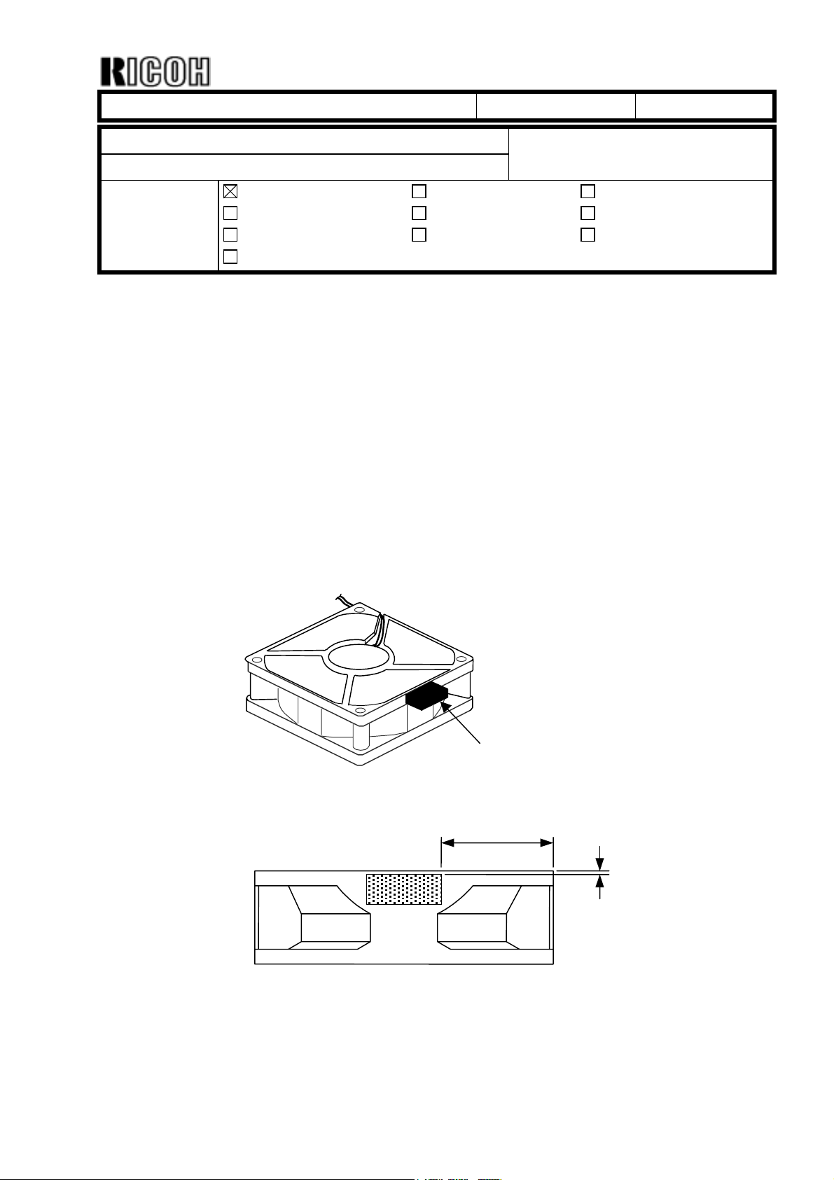
SYMPTOM
Noise can sometimes be heard from the IPU fan motor while the machine is in standby
mode.
CAUSE
In slow speed mode, the reduced speed of the motor can sometimes cause the casing to
resonate.
SOLUTION
Attach the B0171924 damper to the IPU cooling fan as shown below.
Label
B0171924
30 ± 5 mm
1 ± 1 mm
Page 5

echnical Bulletin
T
PAGE: 1/1
Model:
Subject:
From:
Iris2/Lilac2 (Fax Option)
Message when install fax unit
Technical Services Dept., GTS Division
Classification:
Troubleshooting
Mechanical
Paper path
Other (Additional information)
Part information
Electrical
Transmit/receive
Date:
31-Jan-01
Prepared by:
No.:
RB017004
M. Tsuyuki
Action required
Service manual revision
Retrofit information
If a fax comes in while the machine is in Energy Saver Mode, there are some cases where
the connection is lost because the FCU is not able to come on line fast enough. This is
because it waits for the main board wakeup signal. To ensure that incoming transmissions
are properly received, the FCU in all production units will bring itself on line instead.
However, as a minor side effect:
The following is displayed only when the main power is turned on for the first time following
installation. This is because the main board has not yet confirmed the area and language
information with the FCU:
" Area or Language of ROM is different. Please check ROM version".
Action:
Simply press “OK” and the display will be cleared.
Page 6
echnical Bulletin
T
PAGE: 1/1
Model:
Subject:
From:
Iris2/Lilac2
Service Manual
Technical Services Dept., GTS Division
Classification:
Troubleshooting
Mechanical
Paper path
Other ( )
Part information
Electrical
Transmit/receive
Date:
31-Jan-01
Prepared by:
Please correct your service manual as follows.
ItemPage Position
Incorrect Correct
1-4
1-28
2-21 14 lines from the top Capacity of the oil tank is
3-17 2 lines from the bottom …., hook the toner replacement
7-4 SC 193
7-29 Self check result table Displayed Value ‘85’
Power Consumption
Stand-by:
Copying
Weight
B018:
B017
PCB4 -
PCB17
Possible Cause/
Troubleshooting Procedure
0.4 kW
1.1 kW
108 kg
112 kg
Delete function:
Analyzes image for anticounterfeiting (B017/B018)
increased from 350cc to 498cc.
tool on the hunger [B] ….
1. test the scanner IPU board
(SP 4-904-01 and 002). If not
OK, replace the scanner IPU
board.
2. Replace the IDU board.
No.:
RB017005
M. Tsuyuki
Action required
Service manual revision
Retrofit information
0.2 kW
0.7 kW
108 kg (237 lbs.) / NA
109 kg (239.8 lbs.) / EU,AA
111 kg (244.2 lbs.) / NA
112 kg (246.4 lbs.) / EU,AA
Add function:
Analyzes image for anticounterfeiting (B017/B018)
-
Capacity of the oil tank is
increased from 350cc to 430cc.
…., hook the toner replacement
tool on the hanger [B] ….
[A258/A259/A260]
1. Test the scanner IPU board
(SP 4-904-01 and 002). If not
OK, replace the scanner IPU
board.
2. Replace the IDU board.
[B017/B018]
Replace the scanner IPU
board.
Displayed Value ‘89’
Page 7
echnical Bulletin
T
PAGE: 1/3
Model:
Subject:
From:
Iris2/Lilac2
Firmware Modification History
Technical Services Dept., GTS Division
Classification:
Troubleshooting
Mechanical
Paper path
Other ( )
Part information
Electrical
Transmit/receive
Date:
26-Feb-01
Prepared by:
No.:
RB017006
M. Tsuyuki
Action required
Service manual revision
Retrofit information
Lilac2
Version Contents of Modification Remarks
1.132
1 To remove 12 mm banding within 30 mm from the leading edge, the OFF
timing of the revolver motor was changed.
2 To prevent offset image if the following conditions 1 and 2, or 1 and 3
occur at the same time, ON/OFF timing of the separation corona was
changed.
1) Low humidity (example: 20°C,10% or 10°C,15%)
2) Full color (multi-copy), longer than A4 (8.5x11) sideways, from the 3
copy.
3) Making a mono color copy within 1 minute after making full color
copies (longer than A4 [8.5x11] sideways.
rd
3 Do the main corona wire cleaning during developer setup (SP2-225-X) to
prevent uneven image at installation.
4 The following problem was corrected:
The LED for the fax key stays red after clearing a duplex jam.
5 The following problem was corrected:
When scanning A4 (8.5x11) or A3 (11x17) size using the ADF and a Fiery
controller, the scanned image becomes white.
Ver. 1.104 1.132
B017-14 1st Mass Pro. L0861020001
B017-15 1st Mass Pro. H6010200001
B017-17 1st Mass Pro. H60103XXXX
B017-22 1st Mass Pro. H6010100035
B017-24 1st Mass Pro. L0861020016
B017-26 1st Mass Pro. 4E50210001
B017-27 1st Mass Pro. H6010100155
B017-29 1st Mass Pro. H6010200181
Page 8
echnical Bulletin
T
PAGE: 2/3
Model:
Iris2/Lilac2
Date:
26-Feb-01
No.:
RB017006
Iris2
Version Contents of Modification Remarks
1.072
1 To remove 12 mm banding within 30 mm from the leading edge, the OFF
timing of the revolver motor was changed.
2 To prevent offset image if the following conditions 1 and 2, or 1 and 3
occur at the same time, ON/OFF timing of the separation corona was
changed.
4) Low humidity (example: 20°C,10% or 10°C,15%)
5) Full color (multi-copy), longer than A4 (8.5x11) sideways, from the 3
copy.
6) Making a mono color copy within 1 minute after making full color
copies (longer than A4 [8.5x11] sideways.
3 Do the main corona wire cleaning during developer setup (SP2-225-X) to
prevent uneven image at installation.
4 The following problem was corrected:
The LED for the fax key stays red after clearing a duplex jam.
5 The following problem was corrected:
When scanning A4 (8.5x11) or A3 (11x17) size using the ADF and a Fiery
controller, the scanned image becomes white.
rd
Ver. 1.064 1.072
B018-14 1st Mass Pro. L087102XXXX
B018-15 1st Mass Pro. H59102XXXX
B018-17 1st Mass Pro. H59102XXXX
B018-22 1st Mass Pro. H5910100072
B018-24 1st Mass Pro. L0871020001
B018-26 1st Mass Pro. 4E40210001
B018-27 1st Mass Pro. H59102XXXX
B018-29 1st Mass Pro. H5910200240
Page 9
echnical Bulletin
T
PAGE: 3/3
Model:
Iris2/Lilac2
Date:
26-Feb-01
No.:
RB017006
IPU (Iris2/Lilac2)
Version Contents of Modification Remarks
1 The separation threshold level for letter and photo was changed.1.05
2 The following problem was fixed.
When scanning A4 or A3 size using the ADF and Fiery controller, the
scanned image becomes white. At least the Main or IPU program should
be upgraded.
Ver. 1.04 1.05
B017-14 1st Mass Pro. L0860120001
B017-15 1st Mass Pro. H6001100001
B017-17 1st Mass Pro. H6001100021
B017-22 1st Mass Pro. H6001100121
B017-24 1st Mass Pro. L0860120007
B017-26 1st Mass Pro. 4E51100001
B017-27 1st Mass Pro. H6001100274
B017-29 1st Mass Pro. H6001100524
B018-14 1st Mass Pro. L087012XXXX
B018-15 1st Mass Pro. H5901100001
B018-17 1st Mass Pro. H5901100020
B018-22 1st Mass Pro. H5901100368
B018-24 1st Mass Pro. L0870120001
B018-26 1st Mass Pro. 4E41200001
B018-27 1st Mass Pro. H5901100695
B018-29 1st Mass Pro. H5901101003
Page 10
echnical Bulletin
T
PAGE: 1/1
Model:
Subject:
From:
Iris2/Lilac2
Note when remove and install the drawer unit
Technical Services Dept., GTS Division
Classification:
Troubleshooting
Mechanical
Paper path
Other (Note)
Part information
Electrical
Transmit/receive
Date:
13-Mar-01
Prepared by:
No.:
RB017007
M. Tsuyuki
Action required
Service manual revision
Retrofit information
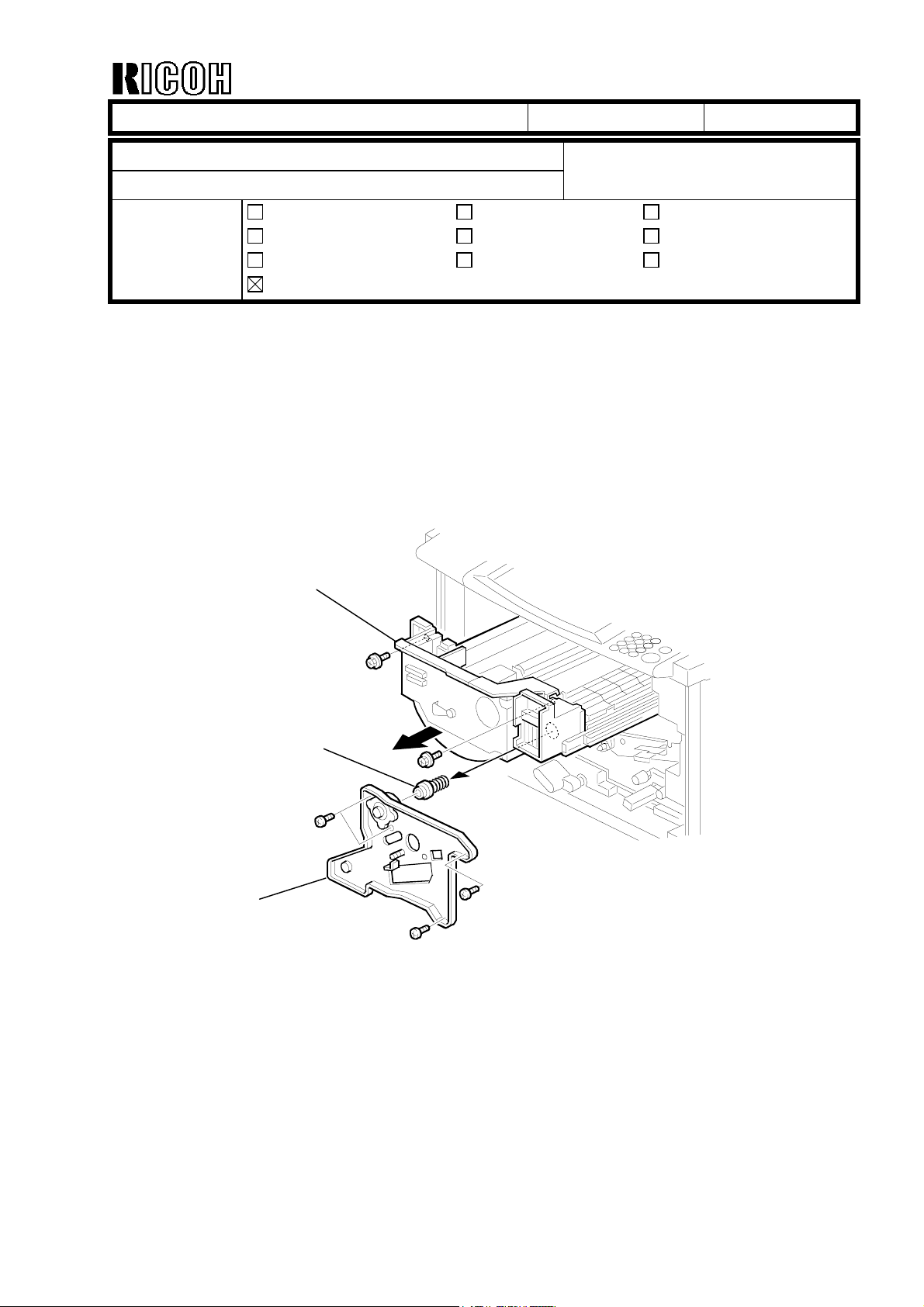
Please note the following when removing and installing the drawer unit.
When removing the drawer unit [A], remove the spring and its holder [B] when detaching
the transfer belt unit stay [C]. Otherwise, the spring and its holder can drop out when the
drawer unit is pulled out. In addition, the spring and holder may spring out when the
drawer unit is pushed in at unit installation.
[C]
[A]
[B]
Page 11

echnical Bulletin
T
PAGE: 1/2
Model:
Subject:
From:
Classification:
The E-310 Ver.1.1 machines (G938-04, G938-05) were released from March, 2001.
Iris2/Lilac2 (Controller E-310)
E-310 Ver.1.1 (128MB) model release
Technical Services Dept., GTS Division
Troubleshooting
Mechanical
Paper path
Other ( )
Part information
Electrical
Transmit/receive
Date:
21-Mar-01
Prepared by:
No.:
RB017008
Chisato Tsuji
Action required
Service manual revision
Retrofit information
Machine Codes and Default System/User Software Versions
Machine Memory Configuration User CD System CD (Service Kit)
G938-01 US 256 MB (128 x 2) Ver.1.0 (G9385081) Ver.1.0 (G9389500)
G938-02 Int'l 256 MB (128 x 2) Ver.1.0 (G9385081) Ver.1.0 (G9389500)
G938-04 US 128 MB Ver.1.1 (G9385181) Ver.1.1 (G9389501)
G938-05 Int'l 128 MB Ver.1.1 (G9385181) Ver.1.1 (G9389501)
Software Interchangeability (User/System)
Interchangeability
System Software (Ver.1.0/Ver.1.1) X/O
User Software (Ver.1.0/Ver.1.1) X/X
X/O as a set
Ricoh Serial Number Format
Y= Last digit of the year (e.g. 2001 is 1).
MM = Month + 84 (e.g. January is 85, December is 96).
Machine: Memory: Serial Number:
G938-01 US 256 MB (128 x 2)
G938-02 Int'l 256 MB (128 x 2)
G938-04 US 128 MB
G938-05 Int'l 128 MB
P47YMM00001 - 19999
P47YMM50001 - 69999
P47YMM20001 - 49999
P47YMM70001 - 99999
Differences between E-310 Ver.1.0 (G938-01, -02) and Ver.1.1 (G938-04, -05)
!
Components:
P/N for
G938-01
G938-02
G9385020 G9385020 128MB DIMM
G9385081 G9385181
(EFI P/N 45021491:
10pcs)
P/N for
G938-04
G938-05
Description: Q'ty: Note:
2
(G938-01,-02)
1
(G938-04,-05)
User Software 1
P/N is the same but the
Q'ty is different
Page 12

echnical Bulletin
T
PAGE: 2/2
Model:
G9385082 G9385182
G9389500
changed to
G9389501
from March
See MB No.
MG938001
!
Iris2/Lilac2 (Controller E-310)
P/N for
G938-01
G938-02
(EFI P/N 45021468)
G9389501
* will be
2001
Notes on software (when both the System Software Ver.1.1 and User Software 1.1 are used):
(EFI P/N 45021493)
P/N for
G938-04
G938-05
Description: Q'ty: Note:
Doc Pack English 1
Service Kit
(System CD)
Date:
21-Mar-01
Getting Started (Same)
Color Guide (Same)
Job Management Guide
(Same)
Printing Guide (Same)
Configuration Guide (Same)
Release Notes 1.1 (New)
Addendum (New)
1 Please order this item as
soon as possible.
No.:
RB017008
1. A new scanning compression technology has been applied, which uses just 128 MB of memory.
Note: Scanning quality is identical to that of the V1.0 256MB.
2. Expert color settings can now be accessed from the printer driver. There will be a User
Addendum packed together with the controller explaining this function.
3. The Job Cancel procedure from the operation panel will be modified as follows:
When an error occurs, the error message itself (e.g. "Load A4...") will be displayed on the panel
instead of the Job Cancel message. Users can view the Job Cancel message by using the scroll
button on the panel.
Important Notes:
Do not install system Ver.1.0 in 128 MB machines, as the scanning quality may be very poor.
Page 13

Reissued: 23-Apr-01
echnical Bulletin
T
PAGE: 1/8
Model:
Subject:
From:
Iris2/Lilac2
Firmware Modification History
Technical Services Dept., GTS Division
Classification:
Troubleshooting
Mechanical
Paper path
Other ( )
Part information
Electrical
Transmit/receive
Date:
26-Feb-01
Prepared by:
This RTB explains the firmware modification history.
Table of contents
Page
1. Firmware information 2
1.1 Iris2 firmware 2
1.2 Lilac2 firmware 2
1.3 IPU firmware 2
No.:
RB017006a
M. Tsuyuki
Action required
Service manual revision
Retrofit information
1.4 FCU firmware 2
2. Iris2 firmware 3
2.1 Modification history 3
2.2 Contents of modification 4
2.3 Cut-in serial number information 4
3. Lilac2 firmware 5
3.1 Modification history 5
3.2 Contents of modification 5
3.3 Cut-in serial number information 6
4. IPU firmware 7
4.1 Modification history 7
4.2 Contents of modification 7
4.3 Cut-in serial number information 7
5. FCU firmware 8
5.1 Modification history 8
5.2 Contents of modification 8
5.3 Cut-in serial number information 8
Page 14

Reissued: 23-Apr-01
echnical Bulletin
T
PAGE: 2/8
Model:
Iris2/Lilac2
1. Firmware Information
1.1 Iris2 Main Firmware
Type P/N Model Code
(B018)
NA B0185197 14, 15,17
EU B0185198 22, 24, 26, 27, 29
EU2 B0185181 Language software
EU3 B0185182 Language software
EU4 B0185183 Language software
Languages in boldface are the defaults.
1.2 Lilac2 Main Firmware
Type P/N Model Code
(B017)
NA B0175197 14, 15,17
EU B0175198 22, 24, 26, 27, 29
EU2 B0175181 Language software
EU3 B0175182 Language software
Languages in boldface are the defaults.
English
English
Spanish
Portugese
Russian
English
English
Spanish
Norwegian
Date:
26-Feb-01
Language
French Spanish Brazilian
French German Italian
Dutch Danish Swedish
Norwegian Czech Polish
English - -
Language
French Spanish Brazilian
French German Italian
Dutch Danish Swedish
Portugese Czech Polish
No.:
RB017006a
1.3 IPU Firmware
P/N Model Code
B018 14, 15, 17, 22, 24, 26, 27, 29B0175133
B017 14, 15, 17, 22, 24, 26, 27, 29
1.4 FCU Firmware
Type P/N Model Code
(B383)
NA B3835582 17
EU B3835584 27
EU2 B3835585 Language software
EU3 B3835586 Language software
EU4 B3835587 Language software
Languages in boldface are the defaults.
English
English
Spanish
Portugese
Italian
Language
French Spanish
French German
Dutch Danish
Norwegian Czech
Swedish Polish
Page 15

Reissued: 23-Apr-01
echnical Bulletin
T
PAGE: 3/8
Model:
Iris2/Lilac2
2. Iris2 Main Firmware
2.1 Modification History
NA Model
Part Number/
Suffix
B0185197G 1.064 9AF7 1st mass production
H 1.072 3546
J1.09DED0
EU Model
Part Number/
Suffix
B0185198G 1.064 F5B6 1st mass production
H 1.072 5F3B
J 1.09 F89F
Version C.SUM Production
Refer to 2.3
Version C.SUM Production
Refer to 2.3
Date:
26-Feb-01
No.:
RB017006a
EU2 Model
Part Number/
Suffix
B0185181 1.064 76B 1st mass production
A 1.072 5507
B 1.09 678C
Version C.SUM Production
Refer to 2.3
EU3 Model
Part Number/
Suffix
B0185182 1.064 AC48 1st mass production
A 1.072 C909
B1.09E763
Version C.SUM Production
Refer to 2.3
EU4 Model
Part Number/
Suffix
B0185183 1.064 B0FB 1st mass production
A 1.072 961B
B 1.09 53BC
Version C.SUM Production
Refer to 2.3
Page 16

Reissued: 23-Apr-01
echnical Bulletin
T
PAGE: 4/8
Model:
Iris2/Lilac2
Date:
26-Feb-01
No.:
RB017006a
2.2 Contents of Modification
Version Contents of Modification Remarks
1.064 - This version has been used from the first mass production.
1.072
1.09
1 To remove 12mm banding within 30mm from the leading edge, the OFF
timing of the revolver motor was changed.
2 To prevent offset image if the following conditions 1 and 2, or 1 and 3
occur at the same time, ON/OFF timing of the separation corona was
changed.
1) Low humidity (example: 20°C,10% or 10°C,15%)
2) Full color (multi-copy), longer than A4 (8.5x11) sideways, from the
3rd copy.
3) Making a mono color copy within 1 minute after making full color
copies (longer than A4 (8.5x11) sideways.
3 Perform the main corona wire cleaning during developer setup (SP2-225-
X) to prevent uneven image at installation.
4 The following problem was corrected:
The LED for the fax key stays red after clearing a duplex jam.
5 The following problem was corrected:
When scanning A4 (8.5x11) or A3 (11x17) size using the ADF and a Fiery
controller, the scanned image becomes white.
1 The following problem was fixed.
SC326 may occur if the following 3 conditions are met:
1) Multi-copy run
2) Image rotation mode
3) Suffix of the LD control board P/N (B0175291) is before H.
2 The following problem was fixed.
SC121 may occur if the following 3 conditions are met.
Multi-copy run
1)
2)
Image rotation mode
3)
Suffix of the LD control board P/N (B0175291) is before H.
3 Documents received in night mode are stored as substitution reception
documents and are not printed out.
4 Software modified to so that it can be used with the RSS function.
2.3 Cut-in Serial Number Information
Ver. 1.064 1.072 1.09
B018-14 1st Mass Pro. L087102XXXX
B018-15 1st Mass Pro. H59102XXXX
B018-17 1st Mass Pro. H59102XXXX
B018-22 1st Mass Pro. H5910100072
B018-24 1st Mass Pro. L0871020001
B018-26 1st Mass Pro. 4E40210001
B018-27 1st Mass Pro. H59102XXXX
B018-29 1st Mass Pro. H5910200240
Page 17

Reissued: 23-Apr-01
echnical Bulletin
T
PAGE: 5/8
Model:
Iris2/Lilac2
3. Lilac2 Main Firmware
3.1 Modification History
NA Model
Part Number/
Suffix
B0175197G 1.104 6519 1st mass production
H 1.132 963D
J 1.15 4328
EU Model
Part Number/
Suffix
B0175198G 1.104 C6FD 1st mass production
H 1.132 241A
J 1.15 116E
EU2 Model
Part Number/
Suffix
B0175181 1.104 A147 1st mass production
A1.132EB53
B 1.15 4501
Version C.SUM Production
Refer to 3.3
Version C.SUM Production
Refer to 3.3
Version C.SUM Production
Refer to 3.3
Date:
26-Feb-01
No.:
RB017006a
EU3 Model
Part Number/
Suffix
B0175182 1.104 A5D9 1st mass production
A 1.132 22EA
B 1.15 29DD
Version C.SUM Production
Refer to 3.3
Page 18

Reissued: 23-Apr-01
echnical Bulletin
T
PAGE: 6/8
Model:
Iris2/Lilac2
Date:
26-Feb-01
No.:
RB017006a
3.2 Contents of Modification
Version Contents of Modification Remarks
1.104 - This version has been used from the first mass production.
1.132
1.15
1 To remove 12mm banding within 30mm from the leading edge, the OFF
timing of the revolver motor was changed.
2 To prevent offset image if the following conditions 1 and 2, or 1 and 3
occur at the same time, ON/OFF timing of the separation corona was
changed.
1) Low humidity (example: 20°C,10% or 10°C,15%)
2) Full color (multi-copy), longer than A4 (8.5x11) sideways, from the
3rd copy.
3) Making a mono color copy within 1 minute after making full color
copies (longer than A4 (8.5x11) sideways.
3 Perform the main corona wire cleaning during developer setup (SP2-225-
X) to prevent uneven image at installation.
4 The following problem was corrected:
The LED for the fax key stays red after clearing a duplex jam.
5 The following problem was corrected:
When scanning A4 (8.5x11) or A3 (11x17) size using the ADF and a Fiery
controller, the scanned image becomes white.
1 The following problem was fixed.
SC326 may occur if the following 3 conditions are met:
1) Multi-copy run
2) Image rotation mode
3) Suffix of the LD control board P/N (B0175291) is before H.
2 The following problem was fixed.
SC121 may occur if the following 3 conditions are met.
1) Multi-copy run
2) Image rotation mode
3) Suffix of the LD control board P/N (B0175291) is before H.
3 Documents received in night mode are stored as substitution reception
documents and are not printed out.
4 Software modified to so that it can be used with the RSS function.
3.3 Cut-in Serial Number Information
Ver. 1.104 1.132 1.15
B017-14 1st Mass Pro. L0861020001
B017-15 1st Mass Pro. H6010200001
B017-17 1st Mass Pro. H60103XXXX
B017-22 1st Mass Pro. H6010100035
B017-24 1st Mass Pro. L0861020016
B017-26 1st Mass Pro. 4E50210001
B017-27 1st Mass Pro. H6010100155
B017-29 1st Mass Pro. H6010200181
Page 19

Reissued: 23-Apr-01
echnical Bulletin
T
PAGE: 7/8
Model:
Iris2/Lilac2
Date:
26-Feb-01
No.:
RB017006a
4. IPU Firmware
4.1 Modification History
Part Number/
Suffix
B0175133D 1.04 E860 1st mass production
E 1.05 2EDD Refer to 4.3
4.2 Contents of Modification
Version Contents of Modification Remarks
1.04 - This version has been used from the first mass production.
Version C.SUM Production
1 The separation threshold level for letter and photo was changed.1.05
2 The following problem was fixed.
When scanning A4 or A3 size using the ADF and Fiery controller, if the
scanned image becomes white, at least the Main or IPU program should
be upgraded.
4.3 Cut-in Serial Number Information
Ver. 1.04 1.05
B018-14 1st Mass Pro. L087012XXXX
B018-15 1st Mass Pro. H5901100001
B018-17 1st Mass Pro. H5901100020
B018-22 1st Mass Pro. H5901100368
B018-24 1st Mass Pro. L0870120001
B018-26 1st Mass Pro. 4E41200001
B018-27 1st Mass Pro. H5901100695
B018-29 1st Mass Pro. H5901101003
B017-14 1st Mass Pro. L0860120001
B017-15 1st Mass Pro. H6001100001
B017-17 1st Mass Pro. H6001100021
B017-22 1st Mass Pro. H6001100121
B017-24 1st Mass Pro. L0860120007
B017-26 1st Mass Pro. 4E51100001
B017-27 1st Mass Pro. H6001100274
B017-29 1st Mass Pro. H6001100524
Page 20

Reissued: 23-Apr-01
echnical Bulletin
T
PAGE: 8/8
Model:
Iris2/Lilac2
5. FCU Firmware
5.1 Modification history
NA model
Part Number/
Suffix
B3835582B 2.17 12C9 1st mass production
EU model
Part Number/
Suffix
B3835584B 2.17 8045 1st mass production
EU2 model
Part Number/
Suffix
B3835585A 2.18 5D8D 1st mass production
Version C.SUM Production
Version C.SUM Production
Version C.SUM Production
Date:
26-Feb-01
No.:
RB017006a
EU3 model
Part Number/
Suffix
B3835586A 2.18 1CDF 1st mass production
Version C.SUM Production
EU4 model
Part Number/
Suffix
B3835587A 2.18 3818 1st mass production
Version C.SUM Production
5.2 Contents of Modification
NA & EU model
Version Contents of Modification Remarks
2.17 - This version has been used from the first mass production.
EU2, EU3 & EU4 model
Version Contents of Modification Remarks
2.18 - This version has been used from the first mass production.
5.3 Cut-in Serial Number Information
Ver. 1.04
B383-17 1st Mass Pro.
B383-27 1st Mass Pro.
Page 21

Reissued: 01-Jun-01
echnical Bulletin
T
PAGE: 1/10
Model:
Subject:
From:
Iris2/Lilac2
Firmware Modification History
Technical Services Dept., GTS Division
Classification:
Troubleshooting
Mechanical
Paper path
Other ( )
Part information
Electrical
Transmit/receive
Date:
26-Feb-01
Prepared by:
Firmware modification history.
Table of contents
Page
1. Firmware information 2
1.1 Iris2 firmware 2
1.2 Lilac2 firmware 2
1.3 IPU firmware 2
No.:
RB017006b
M. Tsuyuki
Action required
Service manual revision
Retrofit information
1.4 FCU firmware 2
2. Iris2 firmware 3
2.1 Modification history 3
2.2 Contents of modification 4
2.3 Cut-in serial number information 5
3. Lilac2 firmware 6
3.1 Modification history 6
3.2 Contents of modification 7
3.3 Cut-in serial number information 8
4. IPU firmware 9
4.1 Modification history 9
4.2 Contents of modification 9
4.3 Cut-in serial number information 9
5. FCU firmware 10
5.1 Modification history 10
5.2 Contents of modification 10
5.3 Cut-in serial number information 10
Page 22

Reissued: 01-Jun-01
echnical Bulletin
T
PAGE: 2/10
Model:
Iris2/Lilac2
1. Firmware Information
1.1 Iris2 Main Firmware
Type P/N Model Code
(B018)
NA B0185197 14, 15,17
EU B0185198 22, 24, 26, 27, 29
EU2 B0185181 Language software
EU3 B0185182 Language software
EU4 B0185183 Language software
Languages in boldface are the defaults.
1.2 Lilac2 Main Firmware
Type P/N Model Code
(B017)
NA B0175197 14, 15,17
EU B0175198 22, 24, 26, 27, 29
EU2 B0175181 Language software
EU3 B0175182 Language software
Languages in boldface are the defaults.
English
English
Spanish
Portuguese
Russian
English
English
Spanish
Norwegian
Date:
26-Feb-01
Language
French Spanish Brazilian
French German Italian
Dutch Danish Swedish
Norwegian Czech Polish
English - -
Language
French Spanish Brazilian
French German Italian
Dutch Danish Swedish
Portuguese Czech Polish
No.:
RB017006b
1.3 IPU Firmware
P/N Model Code
B018 14, 15, 17, 22, 24, 26, 27, 29B0175133
B017 14, 15, 17, 22, 24, 26, 27, 29
1.4 FCU Firmware
Type P/N Model Code
(B383)
NA B3835582 17
EU B3835584 27
EU2 B3835585 Language software
EU3 B3835586 Language software
EU4 B3835587 Language software
Languages in boldface are the defaults.
English
English
Spanish
Portuguese
Italian
Language
French Spanish
French German
Dutch Danish
Norwegian Czech
Swedish Polish
Page 23

Reissued: 01-Jun-01
echnical Bulletin
T
PAGE: 3/10
Model:
Iris2/Lilac2
2. Iris2 Main Firmware
2.1 Modification History
NA Model
Part Number/
Suffix
B0185197G 1.064 9AF7 1st mass production
H 1.072 3546
J1.09DED0
K 1.112 82D3
EU Model
Part Number/
Suffix
B0185198G 1.064 F5B6 1st mass production
H 1.072 5F3B
J 1.09 F89F
K 1.112 949B
Version C.SUM Production
Refer to 2.3
Version C.SUM Production
Refer to 2.3
Date:
26-Feb-01
No.:
RB017006b
EU2 Model
Part Number/
Suffix
B0185181 1.064 76B 1st mass production
A 1.072 5507
B 1.09 678C
C 1.112 0487
Version C.SUM Production
Refer to 2.3
EU3 Model
Part Number/
Suffix
B0185182 1.064 AC48 1st mass production
A 1.072 C909
B1.09E763
C 1.112 A284
Version C.SUM Production
Refer to 2.3
EU4 Model
Part Number/
Suffix
B0185183 1.064 B0FB 1st mass production
A 1.072 961B
B 1.09 53BC
C 1.112 6C36
Version C.SUM Production
Refer to 2.3
Page 24

Reissued: 01-Jun-01
echnical Bulletin
T
PAGE: 4/10
Model:
Iris2/Lilac2
Date:
26-Feb-01
No.:
RB017006b
2.2 Contents of Modification
Version Contents of Modification Remarks
1.064 - This version has been used from the first mass production.
1.072
1.09
1.112
1 To remove 12 mm banding within 30 mm from the leading edge, the off
timing of the revolver motor was changed.
2 To prevent offset image if the following conditions 1 and 2, or 1 and 3
occur at the same time, on/off timing of the separation corona was
changed.
1) Low humidity (example: 20°C,10% or 10°C,15%)
2) Full color (multi-copy), longer than A4 (8.5x11) sideways, from the
3rd copy.
3) Making a mono color copy within 1 minute after making full color
copies (longer than A4 (8.5x11) sideways.
3 Perform the main corona wire cleaning during developer setup (SP2-225-
X) to prevent uneven image at installation.
4 The following problem was corrected:
The LED for the fax key stays red after clearing a duplex jam.
5 The following problem was corrected:
When scanning A4 (8.5x11) or A3 (11x17) size using the ADF and a Fiery
controller, the scanned image becomes white.
1 The following problem was fixed.
SC326 may occur if the following 3 conditions are met:
1) Multi-copy run
2) Image rotation mode
3) Suffix of the LD control board P/N (B0175291) is before H.
2 The following problem was fixed.
SC121 may occur if the following 3 conditions are met.
Multi-copy run
1)
2)
Image rotation mode
3)
Suffix of the LD control board P/N (B0175291) is before H.
3 Documents received in night mode are stored as substitution reception
documents and are not printed out.
4 Software modified so that it can be used with the RSS function.
1 The following problem was fixed.
An SC condition may occur at the 2nd copy when the following
conditions are met:
1) More than 2 sheets of A3 originals are set in the DF
2) Black/White or single color mode (Yellow, Magenta or Cyan)
3) Image shift is used (shift to left)
4) A4 paper is selected
2 If APS is unable to detect the paper size when the paper bank is not
installed, the operation panel display shows the 1st tray for the paper bank
as selected (shaded).
3 Software modified for compatibility with the RSS function.
Page 25

Reissued: 01-Jun-01
echnical Bulletin
T
PAGE: 5/10
Model:
Iris2/Lilac2
Date:
26-Feb-01
2.3 Cut-in Serial Number Information
Ver. 1.064 1.072 1.09 1.112
B018-14 1st Mass Pro. L087102XXXX L0871050001 L0871050001
B018-15 1st Mass Pro. H59102XXXX H5910300009 H5910400001
B018-17 1st Mass Pro. H59102XXXX H59104XXXX H59105XXXX
B018-22 1st Mass Pro. H5910100072 H5910300077 H5910400066
B018-24 1st Mass Pro. L0871020001 L0871040001 L0871050011
B018-26 1st Mass Pro. 4E40210001 4E40310001 4E40510001
B018-27 1st Mass Pro. H59102XXXX H5910300245 H5910400201
B018-29 1st Mass Pro. H5910200240 H5910300455 H5910500181
No.:
RB017006b
Page 26

Reissued: 01-Jun-01
echnical Bulletin
T
PAGE: 6/10
Model:
Iris2/Lilac2
3. Lilac2 Main Firmware
3.1 Modification History
NA Model
Part Number/
Suffix
B0175197G 1.104 6519 1st mass production
H 1.132 963D
J 1.15 4328
K 1.172 E16B
EU Model
Part Number/
Suffix
B0175198G 1.104 C6FD 1st mass production
H 1.132 241A
J 1.15 116E
K 1.172 58A2
Version C.SUM Production
Refer to 3.3
Version C.SUM Production
Refer to 3.3
Date:
26-Feb-01
No.:
RB017006b
EU2 Model
Part Number/
Suffix
B0175181 1.104 A147 1st mass production
A1.132EB53
B 1.15 4501
C 1.172 E57F
Version C.SUM Production
Refer to 3.3
EU3 Model
Part Number/
Suffix
B0175182 1.104 A5D9 1st mass production
A 1.132 22EA
B 1.15 29DD
C 1.172 0229
Version C.SUM Production
Refer to 3.3
Page 27

Reissued: 01-Jun-01
echnical Bulletin
T
PAGE: 7/10
Model:
Iris2/Lilac2
Date:
26-Feb-01
No.:
RB017006b
3.2 Contents of Modification
Version Contents of Modification Remarks
1.104 - This version has been used from the first mass production.
1.132
1.15
1.172
1 To remove 12 mm banding within 30 mm from the leading edge, the off
timing of the revolver motor was changed.
2 To prevent offset image if the following conditions 1 and 2, or 1 and 3
occur at the same time, on/off timing of the separation corona was
changed.
1) Low humidity (example: 20°C,10% or 10°C,15%)
2) Full color (multi-copy), longer than A4 (8.5x11) sideways, from the
3rd copy.
3) Making a mono color copy within 1 minute after making full color
copies (longer than A4 (8.5x11) sideways.
3 Perform the main corona wire cleaning during developer setup (SP2-225-
X) to prevent uneven image at installation.
4 The following problem was corrected:
The LED for the fax key stays red after clearing a duplex jam.
5 The following problem was corrected:
When scanning A4 (8.5x11) or A3 (11x17) size using the ADF and a Fiery
controller, the scanned image becomes white.
1 The following problem was fixed.
SC326 may occur if the following 3 conditions are met:
1) Multi-copy run
2) Image rotation mode
3) Suffix of the LD control board P/N (B0175291) is before H.
2 The following problem was fixed.
SC121 may occur if the following 3 conditions are met.
1) Multi-copy run
2) Image rotation mode
3) Suffix of the LD control board P/N (B0175291) is before H.
3 Documents received in night mode are stored as substitution reception
documents and are not printed out.
4 Software modified so that it can be used with the RSS function.
1 The following problem was fixed.
An SC condition may occur at the 2nd copy when the following
conditions are met:
1) More than 2 sheets of A3 originals are set in the DF
2) Black/White or single color mode (Yellow, Magenta or Cyan)
3) Image shift is used (shift to left)
4) A4 paper is selected
2 If APS is unable to detect the paper size when the paper bank is not
installed, the operation panel display shows the 1st tray for the paper bank
as selected (shaded).
3 Software modified for compatibility with the RSS function.
Page 28

Reissued: 01-Jun-01
echnical Bulletin
T
PAGE: 8/10
Model:
Iris2/Lilac2
Date:
26-Feb-01
3.3 Cut-in Serial Number Information
Ver. 1.104 1.132 1.15 1.172
B017-14 1st Mass Pro. L0861020001 L0861040001 L0861050001
B017-15 1st Mass Pro. H6010200001 H6010300008 H6010400007
B017-17 1st Mass Pro. H60103XXXX H6010500086 H6010500086
B017-22 1st Mass Pro. H6010100035 H6010300116 H6010400096
B017-24 1st Mass Pro. L0861020016 L0861030011 L0861050021
B017-26 1st Mass Pro. 4E50210001 4E50310001 4E50510001
B017-27 1st Mass Pro. H6010100155 H6010400149 H6010400179
B017-29 1st Mass Pro. H6010200181 H6010400229 H6010500396
No.:
RB017006b
Page 29

Reissued: 01-Jun-01
echnical Bulletin
T
PAGE: 9/10
Model:
Iris2/Lilac2
Date:
26-Feb-01
No.:
RB017006b
4. IPU Firmware
4.1 Modification History
Part Number/
Suffix
B0175133D 1.04 E860 1st mass production
E1.052EDD
F 1.06 29C1
4.2 Contents of Modification
Version Contents of Modification Remarks
1.04 - This version has been used from the first mass production.
1.06 1 Optimized scanner registration accuracy for 25-70% reduction mode.
Version C.SUM Production
Refer to 4.3
1 The separation threshold level for letter and photo was changed.1.05
2 The following problem was fixed.
When scanning A4 or A3 size using the ADF and Fiery controller, the
scanned image becomes white. At least the Main or IPU program should
be upgraded.
4.3 Cut-in Serial Number Information
Ver. 1.04 1.05 1.06
B018-14 1st Mass Pro. L087012XXXX L0871050001
B018-15 1st Mass Pro. H5901100001 H5910200001
B018-17 1st Mass Pro. H5901100020 H5910200033
B018-22 1st Mass Pro. H5901100368 H5910200065
B018-24 1st Mass Pro. L0870120001 L0871020001
B018-26 1st Mass Pro. 4E41200001 4E40210001
B018-27 1st Mass Pro. H5901100695 H5910300245
B018-29 1st Mass Pro. H5901101003 H5910200240
B017-14 1st Mass Pro. L0860120001 L0861020006
B017-15 1st Mass Pro. H6001100001 H6010200001
B017-17 1st Mass Pro. H6001100021 H6010500086
B017-22 1st Mass Pro. H6001100121 H6010200050
B017-24 1st Mass Pro. L0860120007 L0861020016
B017-26 1st Mass Pro. 4E51100001 4E50210001
B017-27 1st Mass Pro. H6001100274 H6010200104
B017-29 1st Mass Pro. H6001100524 H6010200181
Page 30

Reissued: 01-Jun-01
echnical Bulletin
T
PAGE: 10/10
Model:
Iris2/Lilac2
5. FCU Firmware
5.1 Modification history
NA model
Part Number/
Suffix
B3835582B 2.17 12C9 1st mass production
EU model
Part Number/
Suffix
B3835584B 2.17 8045 1st mass production
EU2 model
Part Number/
Suffix
B3835585A 2.18 5D8D 1st mass production
Version C.SUM Production
Version C.SUM Production
Version C.SUM Production
Date:
26-Feb-01
No.:
RB017006b
EU3 model
Part Number/
Suffix
B3835586A 2.18 1CDF 1st mass production
Version C.SUM Production
EU4 model
Part Number/
Suffix
B3835587A 2.18 3818 1st mass production
Version C.SUM Production
5.2 Contents of Modification
NA & EU model
Version Contents of Modification Remarks
2.17 - This version has been used from the first mass production.
EU2, EU3 & EU4 model
Version Contents of Modification Remarks
2.18 - This version has been used from the first mass production.
5.3 Cut-in Serial Number Information
Ver. 1.04
B383-17 1st Mass Pro.
B383-27 1st Mass Pro.
Page 31

!"#$% T
echnical Bulletin
PAGE: 1/1
Model
Subject:
From:
: Iris2/Lilac2
Language in Service Mode
Technical Services Dept., GTS Division
Classification:
Troubleshooting
Mechanical
Paper path
Other ( )
Part information
Electrical
Transmit/receive
Date:
04-Jun-01
Prepared by:
No.:
RB017009
M. Mano
Action required
Service manual revision
Retrofit information
Symptom
In fax service mode, the phrases listed below are not displayed in English.
(English is used as the service mode display language in all models).
Phrase: EU1 EU2 EU3 EU4
“Enter Number” English Spanish Norwegian Italian
“Prev.” English Spanish Norwegian Italian
“Next” English Spanish Norwegian Italian
“Prev Menu” English Spanish Norwegian Italian
“Printing. Please wait!” English Spanish Norwegian Italian
Cause
In fax service mode, the machine selects the 1st language for displays that are common to fax SP
and UP modes (i.e., the above phrases). The first languages for each version are as follows:
st
Firmware: 1
EU1 English French German
EU2 Spanish Dutch Danish
EU3 Norwegian Portuguese Czech
EU4 Italian Swedish Polish
This is a limitation of fax service mode for this model.
language 2nd language 3rd language
 Loading...