

Page 1

T
echnical
B
ulletin
PAGE: 1/1
Model:
Subject:
From:
Classification:
Installation Procedure
Please add the following steps after step 24 on page 3-58 of the service manual.
Iris/Lilac
Color Controller Installation Procedure
Technical service Dept., GTS Division
Troubleshooting
Mechanical
Paper path
Other ( )
25. Turn on the machine.
If the machine is A259 or A260, skip the remainder of this step.
For A258 machines, use SP7-801-000 to confirm that the firmware version of
the main control board is v.6.43 or later. If it is not, the copier's firmware must
be upgraded (to allow the controller connection).
26. Change SP3-125-000 from 0 (Default) to 2.
27. Enter SP3-126-000 then:
A258: Press 1 and #
A259/260: Press ON.
Part information
Electrical
Transmit/receive
Date:
30-Apr-99
Prepared by:
No.:
RA258001
Y. Sasa ki
Action required
Service manual revision
Retrofit information
28. After doing the forced process control self check, check that the result is “1”
(successful) using SP3-975. (A259/260 machines automatically display the
result on the screen). If the result code is a number other than 1, consult the
error code chart (see the troubleshooting section of the service manual).
29. Do the ACC for printer. If necessary, do the AutoCal procedure of the controller
calibration.
30. Check SP6-910-000. The setting should be “1” for the controller.
-Explanationz SP3-125-000 [Potential Control] (0: Auto, 1: FIX, 2: Auto+2/3 Spd)
0: The machine does the process control self check only at normal speed for
1: The machine does not do the process control self check. It applies fixed
2: The machine does the process control self check at normal speed for copier
copier mode.
voltages for Vb, Vd, and Vl.
mode. The machine then confirms the process control self check information
at 2/3 speed for the printer mode. Therefore it takes a little longer to finish the
process control self check.
z SP6-910-000 [Printer/Scanner key setting]
When installing the E-300 controller, this should be set to 1. If the setting is 0,
the Printer/Scanner key on the controller LCD panel does not work.
Page 2

RICOH Technical
Bulletin
PAGE: 1/2
Model:
Subject:
From:
Classification:
This RTB explains the user tools (system settings) which affect the copier/printer
operations.
1. AOF Setting
When installation of system software is nece ssary, make sure that the AOF setting is OFF
using the user tools.
Iris/Lilac
User tools for the printer system
Technical Service Dept., GTS Division
Troubleshooting
Mechanical
Paper path
Other ( )
Part information
Electrical
Transmit/receive
Date:
31-May-99
Prepared by:
No.:
RA258002
Y. SASAKI
Action required
Service manual revision
Retrofit information
If the AOF setting is ON, the machine might go into the sleep mode and the system
software download might fail.
2. System Reset: (Default: On [60 seconds])
When the copier is in the following modes, print jobs are not accepted. The “System
Reset” resets these modes when the copier is left unoperated for the selected period of
time.
Interrupt mode (The condition in which the interrupt key is pressed.)
l
Sorter mode
l
Duplex mode
l
ADF mode (after cancelling ADF mode, the originals which are in the ADF are
l
automatically fed out.)
Note: The above modes are not reset by the “Copy Reset”.
3. Interleave Print (Default: On)
When “Interleave Print” is on, the machine accepts a print job while copying, or vice versa.
The copy job and the print job are printed alternately 1 sheet at a time in normal mode, or
2 sheets at a time in double-page transfer mode (two pages at once on the transfer belt).
When the setting is off, the machine prints the first job completely, then it waits for the
Function Reset interval, and the second job is started.
Page 3

RICOH Technical
Bulletin
PAGE: 2/2
Model:
4. Interleave Priority: (Default: On) (A259/A260 only)
Do not use this user tool.
5. Function Reset (Default: On [60 seconds])
The “Function Reset” only works when “Interleave Print” is set to OFF.
Iris/Lilac
Date:
31-May-99
No.:
RA258002
Page 4
T
echnical
B
ulletin
PAGE: 1/1
Model:
Subject:
From:
Iris/Lilac
SC Codes
Technical Service Dept., GTS Division
Classification:
Troubleshooting
Mechanical
Paper path
Other ( )
Part information
Electrical
Transmit/receive
Date:
15-Jul-99
Prepared by:
No.:
RA258003
T. Itoh
Action required
Service manual revision
Retrofit information
SC codes 410, 901, and 902 are missing from the service manual. Please correct your
service manual.
SC
Code
SC410 Paper
Item Detection Condition Possible Cause Troubleshooting Procedure
separation
current leak
When the current
leak is detected for
2 seconds while the
paper separation
corona is on.
•
Paper
separation
corona unit not
set properly
•
Corona wire
broken
•
Defective high
voltage supply
board (T2, D)
•
Defective I/O
control board
•
Defective
main control
board
1. Check to see if the separation
corona unit is set properly.
2. Replace the corona wire if it is
broken.
3. Check to see if the connectors are
properly connected.
4. Clean the receptacle.
5. Replace the high voltage supply
board (T2,D).
6. Replace the I/O control board.
7. Replace the main control board.
- Signal Check -
CN227-A1 on the I/O control board
SC901 Upper total
counter error
SC902 Lower total
counter error
•
Feedback
signal stays low
when the main
switch is turned
on.
•
Feedback
signal stays low
just before the
trigger signal
goes on.
•
Feedback
signal stays high
just before the
trigger signal
goes off.
Poor connection
of the connectors
Defective counter
1. Check if the connectors are properly
set.
2. Replace the total counter.
With the current software, SC410 is detected only in the print mode. This SC code was
falsely detected during the development stage, so it was temporarily deleted from the
software. However, the software change was only reflected in the copy mode. The cause
of the false detection was found recently and the modification will be applied. The software
will be modified to reflect this SC code in the copy mode as well.
Page 5
T
echnical
ulletin
B
PAGE: 1/1
Model:
Subject:
From:
Classification:
Please make note of the following remarks in order to prevent damage to the drum
potential sensor and/or detection errors.
Iris/Lilac
Handling of drum potential sensor
Technical Service Dept., GTS Division
Troubleshooting
Mechanical
Paper path
Other ( )
Part information
Electrical
Transmit/receive
Date:
15-Jul-99
Prepared by:
No.:
RA258004
T. Itoh
Action required
Service manual revision
Retrofit information
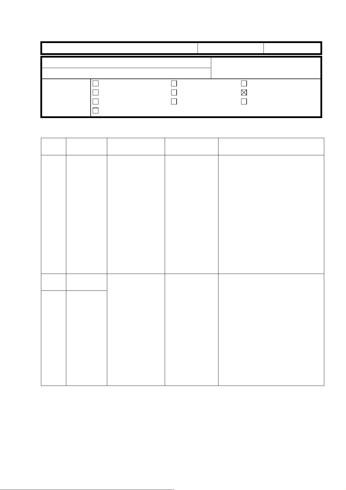
REMARKS
• The sensor is very sensitive. Do not drop the sensor or subject the probe [A] to shock
in any way. Please handle it carefully.
• The service manual shows that the setting powder is applied to the drum in the drum
unit. If the powder goes into the sensor through the window [B] or accumulates around
the window, it may cause the sensor to detect the potential incorrectly. Therefore,
please apply the setting powder to the drum before the drum is placed in the drum unit.
• If the potential sensor is not installed correctly in the drum unit, an error such as 20*,
41* or SC387 will result during the process contro l self-check.
[A]
[B]
Page 6
T
echnical
ulletin
B
PAGE: 1/2
Model:
Subject:
initialization
From:
Classification:
The following problem was reported from the field.
Iris/Lilac
False Bk Toner end detection / Error 511 at developer
Technical Service Dept., GTS Division
Troubleshooting
Mechanical
Paper path
Other ( )
Part information
Electrical
Transmit/receive
Date:
15-Jul-99
Prepared by: T. Itoh
No.:
RA258005
Action required
Service manual revision
Retrofit information
SYMPTOM
1. False Bk toner end detection during developer initialization
2. Developer setup error code 511 during developer initialization
CAUSE
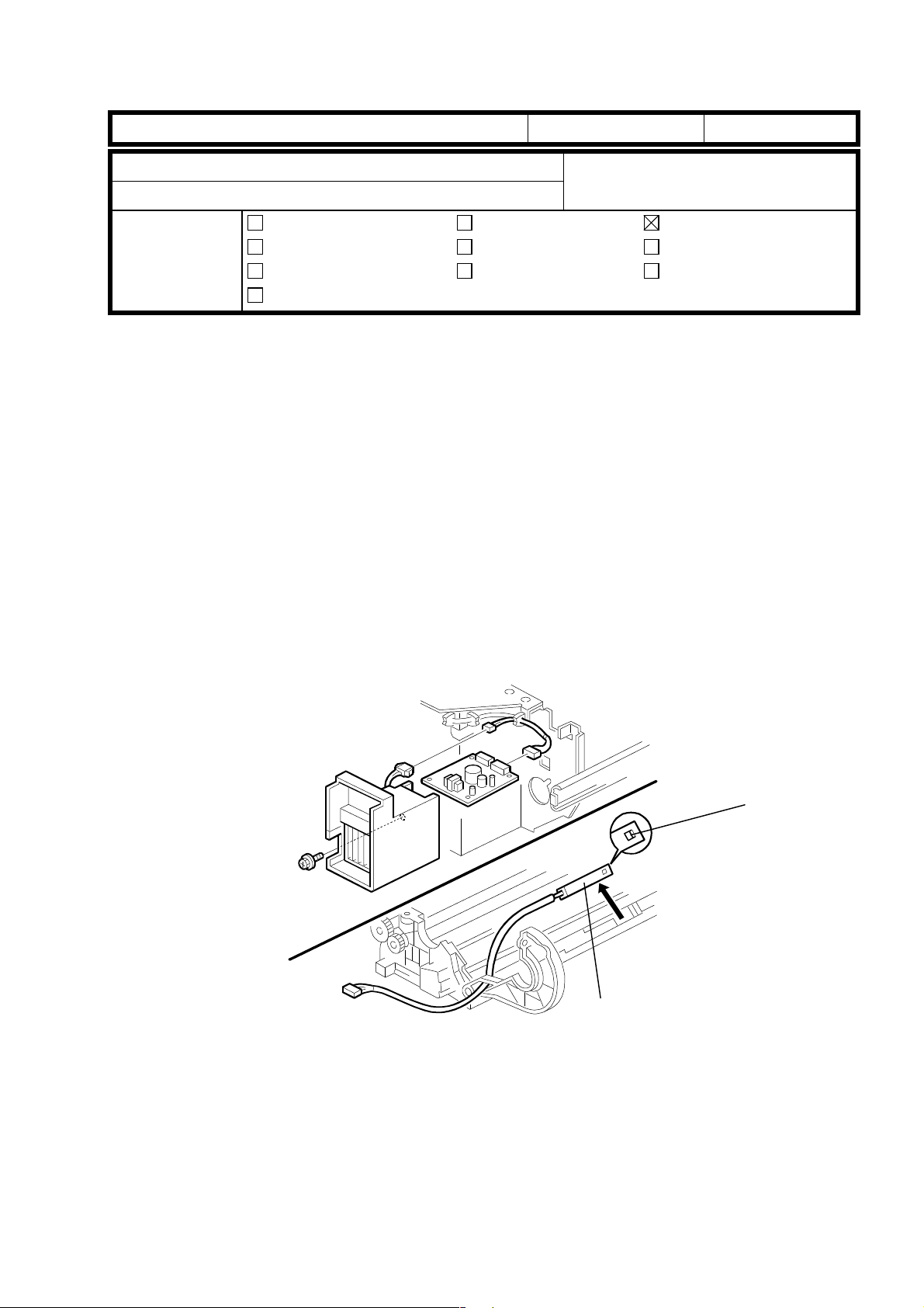
1. The toner supply motor gear [A] and toner supply gear [B] were not properly engaged.
This caused the toner to be not supplied. The toner supply motor may have been
incorrectly positioned and then secured in this position during the production stage. In
such a case, either the motor gear [A] did not touch the toner supply gear [B] and/or the
gears were engaged too tightly, causing the gear shafts [C] to bend.
2. The toner supply gear [B] was broken. When the drawer unit is inserted in the machine
with the development unit located at the development position, the toner supply gear [B]
contacts the motor gear [A]. This may cause the gear [B] to be broken.
[A]
[B]
[C]
Page 7
T
echnical
ulletin
B
PAGE: 2/2
Model:
Iris/Lilac
Date:
15-Jul-99
No.:
RA258005
SOLUTION
Production Field
1 It has been ensured that
the motor was properly
placed and secured in
the correct position. This
procedure has been
reflected in production
runs from April’99
onward.
2 When inserting the drawer unit into the machine, place the development un i t in a
position so that there is sufficient distance between the development sleeve and
the drum. Insert the drawer unit.
When installing machines produced in February and
March, check whether the toner supply motor is properly
positioned after the drawer unit is pulled out and make
sure that the plastic part (black) [A] is correctly placed in
the cutout in the rear frame. (Please refer to the picture
below this table.)
If the motor is not correctly positioned, remove the
motor.
If the gears on the motor shaft are properly engaged,
•
reposition the motor in the cutout properly.
If the gears on the motor shaft are not properly
•
engaged or the shafts have already been bent,
replace the motor.
Rotate the revolver counterclockwise so that the actuator [B] is positioned inside
the dotted lines as shown in the illustration.
[A]
[C]
[B]
Page 8
T
echnical
B
ulletin
PAGE: 1/2
Model:
Subject:
From:
Classification:
Iris/Lilac
Toner Hopper Seal
Technical Service Dept., GTS Division
Troubleshooting
Mechanical
Paper path
Other ( )
Part information
Electrical
Transmit/receive
Date:
SYMPTOM
The toner hopper seal was damaged and peeled off as
shown in the picture. This caused the fit of the toner
bottle to become tight and/or the toner to leak and
scatter.
CAUSE
The toner hopper seal was not firmly attached to the
toner hopper. Therefore, when the toner bottle was
installed, the seal became torn off.
15-Jul-99
Prepared by:
Action required
Service manual revision
Retrofit information
T. Itoh
No.:
RA258006
SOLUTION
• The production procedure has been improved and the toner hopper seal was firmly
attached by pressing. This modification was reflected in the production as shown below.
Model Code
A258-17, 15, 19, 22, 26, 29, 55, 65 From the April ’99 production
A258-27 From the March ‘99 production
A259-All, A260-All From the first mass production
• If this problem is found in the field, replace
the seal by following the procedure described
below.
1. Remove the toner bottle.
2. Pull out the drawer unit.
3. Remove the damaged seal and clean the
surface of the toner hopper where the seal is
attached using alcohol.
NOTE: Make sure that no parts of the torn seal
fall into the toner hopper. If this
happens, white lines may result.
4. Attach the new seal. Make sure that it is
properly fixed in place by pressing firmly.
NOTE: P/N of toner hopper seal : #A2593346.
Page 9

T
echnical
B
ulletin
PAGE: 2/2
Model:
5. Remove the toner collection tray (saucer) and reattach the parts removed.
NOTE:
Iris/Lilac
During the above procedure, take extra caution so that your finger does not
become caught between the drawer unit and revolver.
Date:
15-Jul-99
No.:
RA258006
Page 10
T
Model: Iris/Lilac Date: 15-July-99 No.: RA258007
echnical
ulletin
B
PAGE: 1/1
Subject:
From:
Classification:
Dirty background
Technical Service Dept., GTS Division
Troubleshooting
Mechanical
Paper path
Other ( )
Part information
Electrical
Transmit/receive
Prepared by:
Action required
Service manual revision
Retrofit information
T. Itoh
SYMPTOM
Dirty background faintly appears in copy mode.
CAUSE
The reproduction of highlight areas has been improved from the previous products.
Therefore, the background of an original tends to come through on the copies.
SOLUTION
When receiving a complaint about the dirty background, please explain the above
mentioned cause, then, provide the customer with proper instructions, depending on the
mode selected as shown in the following table.
Symptom/Mode Troubleshooting
Dirty background in FC copy
mode
Back side of the original
appears
Dirty background in B&W
copy mode
(See NOTE.)
NOTE: To reduce the complaints from users, the following SP mode has been added. When
this SP mode is set to 1, Text mode becomes the default setting for the B&W copy mode.
SP mode : 5-005-008
Value range :0 or 1
Default : 0
Setting = 0 :The mode set in the User Tool (Copier Feature) is selected in the B&W copy
mode.
Setting =1 :When the B&W copy mode is selected, Text mode is automatically selected
regardless of the setting in the User Tool.
Instruct the user to select the Auto Image Density mode.
Instruct the user to select the Letter mode.
The Auto Image Density mode detects the background density
of an original, so it does not appear on the copy during the
image processing. This mode is effective for originals that have
high-density backgrounds like newspapers, but not for originals
that have low-density backgrounds.
Page 11
T
echnical
B
ulletin
PAGE: 1/1
Model:
Subject:
From:
Classification:
Iris/Lilac
Dirty marks at 142mm intervals
Technical Service Dept., GTS Division
Troubleshooting
Mechanical
Paper path
Other ( )
Part information
Electrical
Transmit/receive
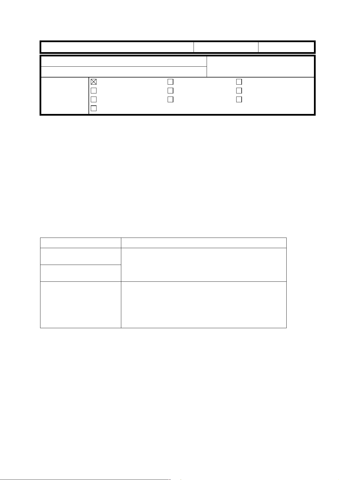
SYMPTOM
Dirty marks appear at 142 mm intervals on outputs.
Date:
15-Jul-99
Prepared by:
No.:
RA258008
T. Itoh
Action required
Service manual revision
Retrofit information
142 mm
CAUSE
Foreign material may be attached to the transfer belt drive roller.
SOLUTION
Clean the transfer belt drive roller.
NOTE: When this pr oblem happens and the drive roller is not cleaned, the transfer belt
itself may develop a ridged deformation along its length as a result of the foreign
material. This line/ridge is reflected in the copies.
Page 12
T
echnical
B
ulletin
PAGE: 1/2
Model:
Subject:
From:
Classification:
Iris/Lilac
Dark spots in solid areas
Technical Service Dept., GTS Division
Troubleshooting
Mechanical
Paper path
Other ( )
Part information
Electrical
Transmit/receive
Date:
15-Jul-99
Prepared by: T. Itoh
No.:
RA258009
Action required
Service manual revision
Retrofit information
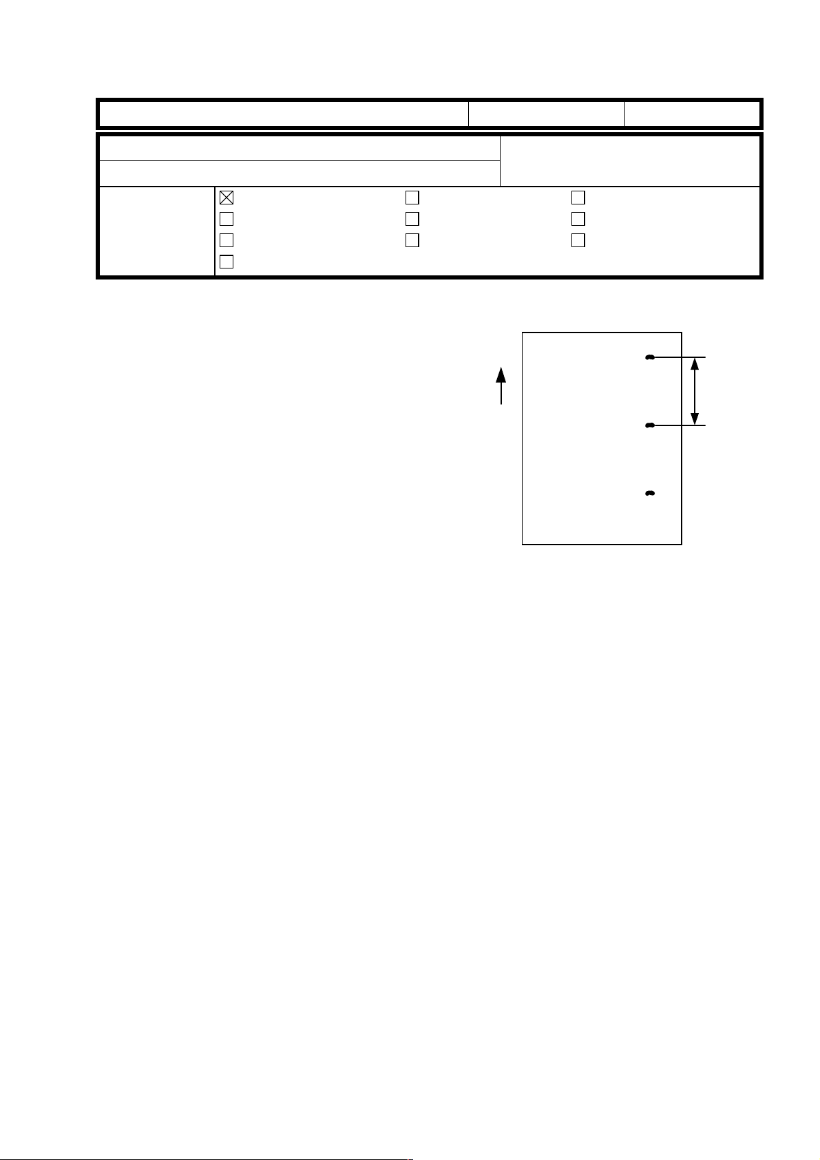
SYMPTOM
In solid areas, dark spots appear as
shown in the illustration.
CAUSE
• The electrical resistance of the image transfer belt has a specified tolerance. If the
electrical resistance is in the lower area of the specification, the pre-fixed transfer bias
becomes higher than the optimum value. In this case, toner transferred onto the belt
tends to be re-attracted to the drum.
• Small carrier particles in the development unit tend to be physically attracted to the
drum. The carriers transferred onto the belt create a gap between drum and belt. Toner
on some parts of the transfer belt where the carriers are transferred are not re-attracted
to the drum due to the gap. The result is dark spots in solid areas as shown above.
• It is known that the dark spots problem tends to appear as the development potential
becomes higher. If the residual voltage detected by the drum potential sensor is 30V or
less, the potential sensor is damaged and this may cause the dark spots.
SOLUTION
1. Check the residual voltage with SP3-111-00. If the voltage is 30V or less, replace the
drum potential sensor and check whether or not the problem disappears. If not, see
step 2.
2. Decrease the transfer belt bias with SP mode as shown below.
In Copy mode: SP2-301-01 to 04
SP Mode Default Step 1 Step 2 Step 3 Step 4
SP2-301-01 1st color 1700 1200 1000 800 600
SP2-301-02 2nd color 1800 1300 1000 800 600
SP2-301-03 3rd color 1900 1400 1000 800 600
SP2-301-04 4th color 2000 1500 1000 800 600
Page 13
T
echnical
B
ulletin
PAGE: 2/2
Model:
NOTE 1:
Decrease the transfer belt bias from the 1st to 4th color by 500 volts each (Step 1) as
•
When the tr ansfer bias is decreased, it may cause the image in t he solid area to
•
In Print mode (2/3 speed):
SP2-301-13 1st color 800 1000 800 600
SP2-301-14 2nd color 900 1100 800 600
SP2-301-15 3rd color 1000 1200 800 600
Iris/Lilac
shown in the above table. Then, check whether the dark spots have disappeared
completely or partially. If the dark spots are still present on the cop y, decrease the bias
again as shown and check the results.
become rough or light since there will be less toner transferred onto the belt and/o r it
may cause firefly spots due to a small amount of clogged toner that causes a gap
between drum and belt. When the belt bias is decreased, check the level of both the
dark spots and rough image/firefly spots. Select the proper bias that gives the best
overall results.
SP2-301-13 to 16
DefaultSP Mode
S/M Ver. 6.43
Date:
15-Jul-99
Step 1 Step 2
No.:
RA258009
SP2-301-16 4th color 1100 1300 800 600
NOTE 2:
The default settings listed in the service manual has been changed in the main
•
software (Ver. 6.43) as shown in the above table.
Refer to the points explained in
•
3. Do the ACC (Auto Color Calibra tion ) after adjusting the transfer bias.
REMARKS:
When adjusting the transfer belt bias for da r k spots, the image quality concern ing the dark
spots, rough image, and firefly spots should be checked whenever the image transfer belt
is replaced. Also, if necessary, readjust the transfer belt bias.
NOTE 1
.
Page 14
T
echnical
B
ulletin
PAGE: 1/2
Model:
Subject:
From:
Classification:
The following problem was reported in the Japanese market. When servicing, please make
note of the following points in order to prevent these problems.
Iris/Lilac
How to route the oil supply tube
Technical Service Dept., GTS Division
Troubleshooting
Mechanical
Paper path
Other ( )
Part information
Electrical
Transmit/receive
Date:
15-Jul-99
Prepared by:
No.:
RA258010
T. Itoh
Action required
Service manual revision
Retrofit information
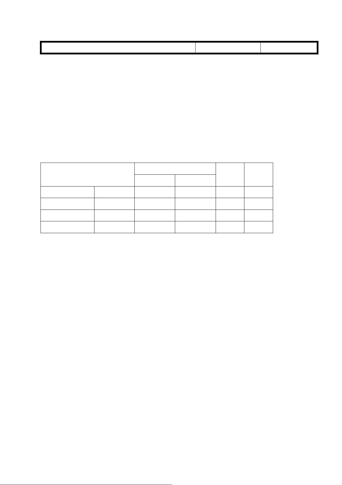
SYMPTOM
• Noise from the fusing section
• The oil supply roller does not rotate.
CAUSE
Silicone oil was not supplied to the oil supply pad and the pad became dry. When the
upper cover was installed, the cover pushed the oil supply tube [A] and the tube bent as
shown in Picture 3.
SOLUTION
In the field
If the oil supply tube [A] is routed as shown in Pictures 1 & 2, the tube may bend when the
upper cover [B] is installed as shown in Picture 3. To prevent this, the oil supply tube has
to be routed as shown in Pictures 4 & 5.
[A]
Picture 1 Picture 2 Picture 3
NG
Picture 4 Picture 5 Picture 6
NG: No Good
[B]
NG
Good
Good
Good
Page 15

T
echnical
B
ulletin
PAGE: 2/2
Model:
Mass production
In order to prevent this problem, the length of the oil supply tube will be changed from
290 mm to 265 mm.
Iris/Lilac
Date:
15-Jul-99
No.:
RA258010
Page 16
T
[A]
echnical
B
ulletin
PAGE: 1/2
Model:
Subject:
From:
Classification:
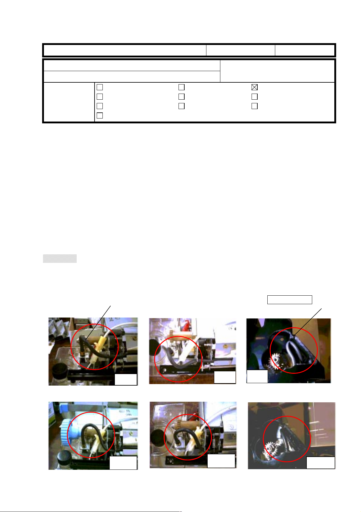
Some problems related to SC 326 or the ARDF were reported from the Japanese market.
These problems were caused by mistakes during installation. Please note the remarks
explained below and keep these items in mind when installing the I/F kit.
Iris/Lilac (Controller Interface Type E)
Remarks at Controller I/F kit installation
Technical Service Dept., GTS Division
Troubleshooting
Mechanical
Paper path
Other ( )
Part information
Electrical
Transmit/receive
Date:
15-Jul-99
Prepared by:
No.:
RA258011
T. Itoh
Action required
Service manual revision
Retrofit information
Remarks
1. Please remember that if the connectors are not properly connected or the shorting
cable is not removed, SC326 will occur. At each step of installation, make sure that:
(1) The 100-pin shielded cable connector [A] is properly connected.
(2) The I/F cable connector [B] is properly connected.
(3) The shorting cable [C] is removed.
(4) The LD flat cable [D] is properly connected.
[B]
[D]
[C]
Page 17

T
echnical
ulletin
B
PAGE: 2/2
Model:
2. Make sure that fiber optic cable connectors are correctly connected to the main control
Iris/Lilac (Controller Interface Type E)
board. White marks are painted on the connectors. If the fiber optic cables are
connected to the wrong connectors on the main board, the ADF will not function.
Date:
15-Jul-99
No.:
RA258011
Page 18
RICOH Technical
Bulletin
PAGE: 1/1
Model:
Subject:
From:
Classification:
It is explained in the service manual that the drum unit [A] should be removed and covered
with a black sheet of paper or 5 or more white sheets when the drawer unit [B] is pulled
out. This will prevent light fatigue, which causes darker bands.
In addition, please make note of the following items when servicing the revolver section.
NOTE:
Iris/Lilac
Remarks at servicing (to prevent drum damage)
Technical Service Dept., GTS Division
Troubleshooting
Mechanical
Paper path
Other ( )
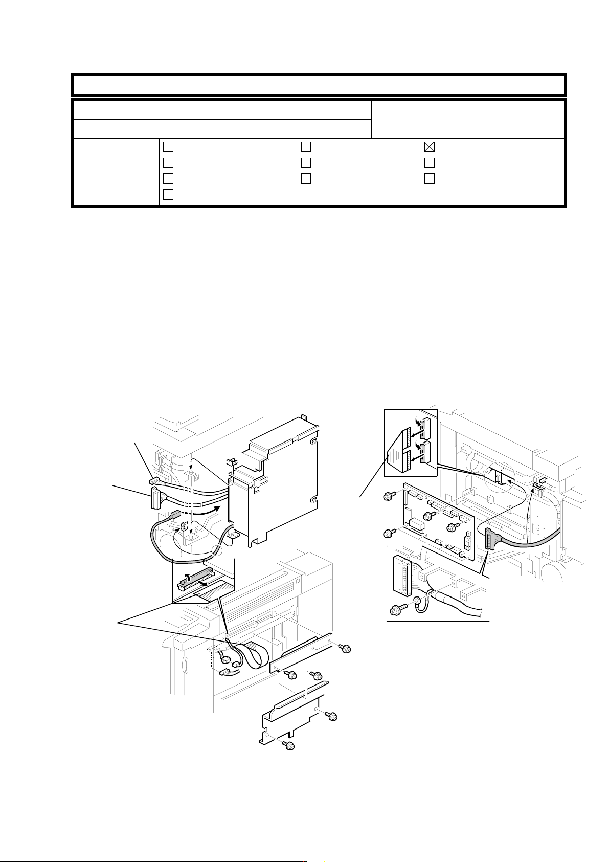
When the revolver unit is rotated without removing the drum unit, the development
sleeve may come in contact with the drum surface. This may damage the drum
and result in dots on the copies. This is due to the fact that normally, the PG (gap
between the drum and sleeve) is properly maintained when the drawer unit is in
the machine. Therefor e, pl eas e make sure that the drum unit is remov ed
whenever servicing the revolver section.
Part information
Electrical
Transmit/receive
Date:
15-Oct.-99
Prepared by:
Action required
Service manual revision
Retrofit information
T. Itoh
No.:
RA258012
NOTE:
NOTE:
Before installing the drum unit in the drawer unit, the revolver unit should be
rotated so that the actuator [C] is positioned in the sensor as explained in RTB
005.
Release the transfer belt pressure whenever pulling out the drawer unit from the
machine. If pulling out the drawer unit without releasing the pressure, the drum
and/or belt may be damaged.
[A]
[B]
[C]
Page 19
RICOH Technical
Bulletin
PAGE: 1/2
Model:
Subject:
From:
Classification:
It was reported that developer spilled out from the development unit during developer
initialization at the time of machine installation. To prevent any future occurrence, please
make note of the following remarks regarding developer replacement and servicing of the
development unit. (Some of these are explained in the service manual, page 3-15.)
Remarks:
1. When replacing the developer, place the development unit on a flat level surface.
2. When attaching th e developer cover [A], set the cover by pressing both sides [B] as
There are 3 cutouts [C] in the developer cover. When positioning the cover on the
development unit, each projection [D] on the development unit should be set into each
cutout properly. If the developer cover is not properly set, developer may leak from the gap
between cover and development unit.
Iris/Lilac
Remarks during developer replacement
Technical Service Dept., GTS Division
Troubleshooting
Mechanical
Paper path
Other ( )
shown below and make sure that the cover is properly positioned.
Part information
Electrical
Transmit/receive
Date:
15-Oct.-99
Prepared by:
Action required
Service manual revision
Retrofit information
T. Itoh
No.:
RA258013
[D]
[C]
[B]
[A]
[D]
Page 20
RICOH Technical
Bulletin
PAGE: 2/2
[B]
Date:
15-Oct.-99
[A]
Model:
3. After pouring developer in the development unit, place the development unit in the
Iris/Lilac
developer scoop-up position [A] as shown. Then, make sure that the developer brush
on the sleeve [B] is properly inserted into the development unit by rotating the gear in
the direction of the arrow as shown below. If the developer is not poured while the unit
is on a flat level surface, the casing might be bent. This causes the developer to spill
out from the development unit. If it happens, the developer should be removed and
placed on a clean sheet of paper, then poured back into the unit.
No.:
RA258013
4. When installing each development unit, do not hold the cente r part [C] of the unit. Both
sides [D] of the unit should be held by hand. If the center part of the development unit
is held by hand, the casing of the unit may bend. The developer may then spill onto
the casing and out of the development unit. If this happens, the developer should be
removed, placed onto a clean sheet of paper and poured back into the development
unit.
[D]
[C]
[D]
Page 21

T
echnical
B
ulletin
PAGE: 1/5
Model:
Subject:
From:
Classification:
It was reported in the Japanese market that image quality problems or SC326 occur due to
a defective BUSSW board in the Interface Kit. This RTB outlines the troubleshooting
procedure.
Iris/Lilac (Controller Interface Type E)
SC326 / Abnormal Image
Technical Service Dept., GTS Division
Troubleshooting
Mechanical
Paper path
Other ( )
Part information
Electrical
Transmit/receive
Date:
15-Nov-99
Prepared by:
No.:
RA258014
T. Itoh
Action required
Service manual revision
Retrofit information
SYMPTOM
1. Blank I mage or Vertic al Li nes
2. SC326
NOTE:
This problem occurs in copy or scanning mode only. It does not occur during print
jobs.
CAUSE
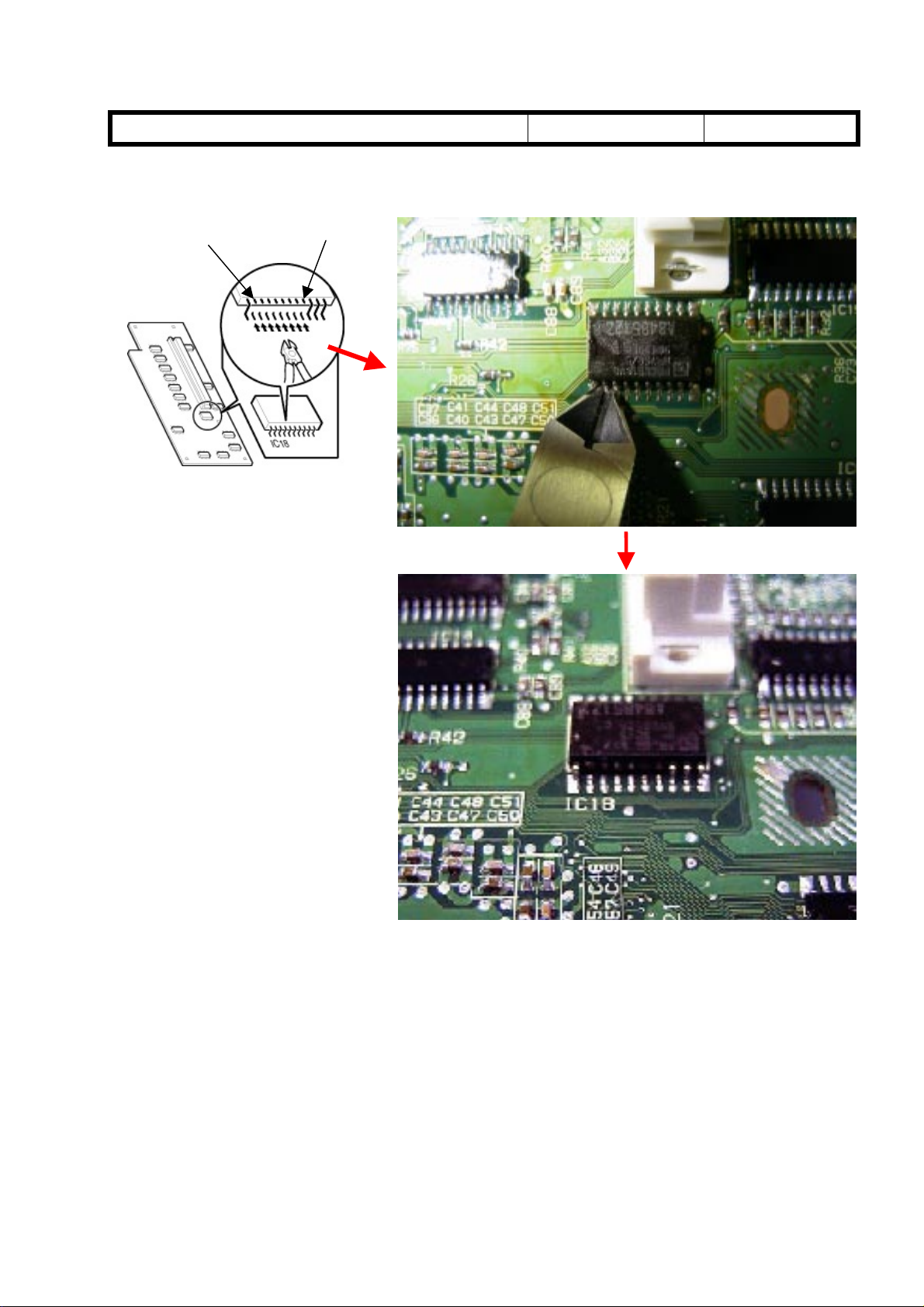
Normally, the input pins (#12 to 17) of IC18 on the BUSSW board are not used for the
function of the IC18. However, due to an error in the software programmed in IC18, these
pins were allocated as output pins. The resulting increase in power consumption causes
the IC to heat up and malfunction.
NOTE:
1. Blank I mage or Vertic al Li nes
When the IC does not renew the scanned image data due to the cause explained above,
blank image or vertical lines appear on the outputs depending on the image of the first line
scanned in.
2. SC326
After analysis and testing of the PCBs returned from the field, it was found that the
cause explained above was a majority of the causes. The other causes are
isolated cases.
• If the first line scanned in is blank, the output is blank.
• If the first line scanned in contains an image, the output will contain vertical lines.
When the IC does not send the LSYNC signal to the ASIC, the FGATE signal cannot be
generated (causing SC326).
Page 22

T
echnical
B
ulletin
PAGE: 2/5
Model:
Iris/Lilac (Controller Interface Type E)
Date:
15-Nov-99
No.:
RA258014
SOLUTION
On the production line
The BUSSW board has been modified twice as shown below. The boards thought to be
causing the problem are #A8485108. The problem does not occur with the Interface Kits
containing #A8485105 or #A8485112, as these boards do not use IC18.
Model Code Modification (1)
Old P/N New P/N
A848-17, 27, 55, 65 A8485105 A8485108
Modification (2)
Old P/N New P/N
A8485108 A8485112
Cut-in Serial Number
Modification (1)
Product Code Cut-in Serial Number
A848-17 H0990300475
A848-27 H0990300944
A848-55 From first mass production
A848-65 From first mass production
NOTE:
Modification (2)
NOTE:
IC18 was added to the PCB for both Japanese and overseas versions since the
board was used for all machines.
Product Code Cut-in Serial Number
A848-17 H0990600001
A848-27 H0990600176
A848-55 L0409060095
A848-65 L0409060180
The same PCB was used for Japanese and overseas versions (with IC18
installed). However, since only the Japanese versions actually use IC18, it was
removed from the overseas versions. The board for all overseas versions has then
been given a new part number.
The action described on the following pages is required on the field machines equipped
with the Interface Kits containing #A8485108. The serial numbers of these Interface Kits
are listed on the next page.
Page 23
T
echnical
B
ulletin
PAGE: 3/5
Model:
Iris/Lilac (Controller Interface Type E)
Date:
15-Nov-99
In the field
Serial number of I/F kits thought to be causing this problem:
Product Code From To
A848-17 H0990300475 H0990500282
A848-27 H0990300944 H0990500512
A848-55 From first mass production L0409050064
A848-65 From first mass production L0409050094
[1] Troubleshoot as shown below when the problem is reported.
Start
In which mode problem
occurs?
Copy or Scan
Regardless of
mode selected
Check the connectors from I/F
kit is properly set to copier.
Printing an internal pattern in
SP 5-955 may specify a cause
of the problem. If the problem
does not occur, this may be
caused by poor connection of
connectors.
(SC326 or abnormal images)
No.:
Refer to RTB #011.
RA258014
NOTE:
NOTE:
Replace BUSSW board
Follow the troubleshooting
Problem solved?
Yes
END
NO
described in SC CODE
section of S/M (page 9).
If the problem is related to IC18, the replaced (old) PCB can be re-used after
cutting pins #12 - 17. If occurrences still continue after cutting the pins, the
problem is being caused by another PCB component.
If the BUSSW board (IC18) causes the problem and the part is not available,
cutting the pins (#12 - 17) of IC18 as explained in section [2] on page 5 of this RTB
solves the problem.
Page 24
T
echnical
B
ulletin
PAGE: 4/5
Model:
- BUSSW Board Replacement Procedure -
Iris/Lilac (Controller Interface Type E)
[B]
[C]
[A]
Date:
15-Nov-99
[D]
No.:
RA258014
1. Turn off the main switch and unplug the power cord.
2. Disconnect the cable(s) from the controller.
3. Remove the exterior covers (used toner cover and I/F unit cover).
4. Remove the controller from the I/F unit (6 screws).
5. Remove the cover plate [A] (2 screws).
6. Remove the AC drive board [B] (4 screws and 2 connectors).
7. Remove the shielding plate [C].
8. Replace the BUSSW board [D] (4 screws, 1 grounding screw, and 2 connectors).
Page 25
T
echnical
B
ulletin
PAGE: 5/5
Model:
[2] Do the following at installation or next visit to prevent any future occurrence.
Iris/Lilac (Controller Interface Type E)
Pin 12
Pin 17
Date:
15-Nov-99
No.:
RA258014
1. Remove the BUSSW board by following the procedure described on the previous page.
2. Using small cutting pliers, cut pins #12 to 17 so that they do not touch other pins or
patterns. This will prevent a short circuit.
3. Remove the cut pins from the board surface.
NOTE:
Be careful not to damage the PCB pattern or cut other pins. If pins #11 or 18 are
cut, this will cause SC326.
Page 26
T
echnical
B
ulletin
PAGE: 1/1
Model:
Subject:
From:
Classification:
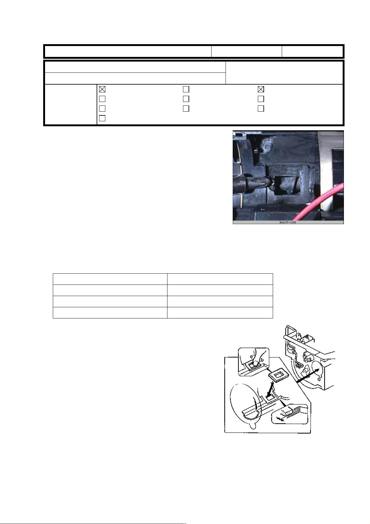
It was reported that connector 408 [A] on the IPU board breaks easily during servicing. It
seems to happen when the connector is opened by hand (e.g. using the forefinger or index
finger). Please make note of the remarks below and keep this point in mind when
accessing the IPU board.
Remarks
Open the connector carefully by using a small-blade screwdriver. (See the photo below.)
Iris/Lilac
Remarks during servicing on IPU board
Technical services Dept., GTS Division
Troubleshooting
Mechanical
Paper path
Other ( )
Part information
Electrical
Transmit/receive
Date:
15-Nov-99
Prepared by:
No.:
RA258015
T. Itoh
Action required
Service manual revision
Retrofit information
[A]
Page 27
RICOH Technical
Revised: 15-Dec-99
Bulletin
PAGE: 1/6
Model:
RTB Correction
The information underlined below has been added.
Subject:
From:
Classification:
It was reported in the Japanese market that image quality problems or SC326 occur due to
a defective BUSSW board in the Interface Kit. This RTB outlines the troubleshooting
procedure.
Iris/Lilac (Controller Interface Type E)
SC326 / Abnormal Image
Technical Service Dept., GTS Division
Troubleshooting
Mechanical
Paper path
Other ( )
Part information
Electrical
Transmit/receive
Date:
15-Nov-99
Prepared by:
Action required
Service manual revision
Retrofit information
T. Itoh
No.:
RA258014a
SYMPTOM
1. Blank I mage or Vertic al Li nes
2. SC326
NOTE:
This problem occurs in copy or scanning mode only. It does not occur during print
jobs.
CAUSE
Normally, the input pins (#12 to 17) of IC18 on the BUSSW board are not used for the
function of the IC18. However, due to an error in the software programmed in IC18, these
pins were allocated as output pins. The resulting increase in power consumption causes
the IC to heat up and malfunction.
NOTE:
1. Blank I mage or Vertic al Li nes
When the IC does not renew the scanned image data due to the cause explained above,
blank image or vertical lines appear on the outputs depending on the image of the first line
scanned in.
2. SC326
After analysis and testing of the PCBs returned from the field, it was found that the
cause explained above was a majority of the causes. The other causes are
isolated cases.
If the first line scanned in is blank, the output is blank.
·
If the first line scanned in contains an image, the output will contain vertical lines.
·
When the IC does not send the LSYNC signal to the ASIC, the FGATE signal cannot be
generated (causing SC326).
Page 28

RICOH Technical
Revised: 15-Dec-99
Bulletin
PAGE: 2/6
Model:
Iris/Lilac (Controller Interface Type E)
Date:
15-Nov-99
No.:
RA258014a
SOLUTION
On the production line
The BUSSW board has been modified twice as shown below. The boards thought to be
causing the problem are #A8485108. The problem does not occur with the Interface Kits
containing #A8485105 or #A8485112, as these boards do not use IC18.
Model Code Modification (1)
Old P/N New P/N
A848-17, 27, 55, 65 A8485105 A8485108
Modification (2)
Old P/N New P/N
A8485108 A8485112
- Additional Information – Modification As shown in the picture, there are two
types of BUSSW board (P/N #A8485108).
Type 1 is the board on which an IC [A] has
been manually soldered. Type 2 contains
an IC18 soldered onto the circuit pattern
by machine.
[A]
Type 1
[A]
Type 2
Type 1 is the board that was modified in
the production (from #A8485 105). This
board contains one of the two ICs as
shown in the picture to the right [A]. The
only difference is in the size.
The function of the additional IC and IC18
is exactly the same. IC18 is soldered onto
the reverse side of the Type 2 board.
Cut-in Serial Number
Modification (1)
Product Code Cut-in Serial Number
A848-17 H0990300475
A848-27 H0990300944
A848-55 From first mass production
A848-65 From first mass production
NOTE:
IC18 was added to the PCB for both
Japanese and overseas versions
since the board was used for all
machines.
Page 29

RICOH Technical
Revised: 15-Dec-99
Bulletin
PAGE: 3/6
Model:
Iris/Lilac (Controller Interface Type E)
Date:
15-Nov-99
No.:
RA258014a
Modification (2)
Product Code Cut-in Serial Number
A848-17 H0990600001
A848-27 H0990600176
A848-55 L0409060095
A848-65 L0409060180
NOTE:
The same PCB was used for Japanese
and overseas versions (with IC18
installed). However, since only the
Japanese versions actually use IC18, it
was removed from the overseas
versions. The board for all overseas
versions has then been given a new
part number.
- Additional Information – Cut-in Serial Number #A8485105 has been modified to #A8485108 by soldering an IC onto the board as
explained. This special modification was not controlled at the factory. Therefore, it is not
possible to specify the exact serial numbers of the I/F units that contain the modified
board. The table below contains our estimation of the serial number. The modification was
applied to a total of 112 boards, which means that 112 of the following 159 I/F units may
contain modified boards.
Serial number No. of units
H0990300648 - 0660 13 unitsA848-17
H0990300692 - 0709 18 units
A848-27
A848-65 L0409030014 - 0043 30 units
H0990301002 - 1015 14 units
H0990301188 - 1202 15 units
H0990301248 - 1316 69 units
Total 159 units
The action described on the following pages is required for the field machines equipped
with the Interface Kits containing #A8485108. The serial numbers of these interface kits
are described below.
In the field
Serial numbers of I/F kits thought to be causing this problem:
Product Code From To
A848-17 H0990300475 H0990500282
A848-27 H0990300944 H0990500512
A848-55 From first mass production L0409050064
A848-65 From first mass production L0409050094
Page 30

RICOH Technical
Revised: 15-Dec-99
Bulletin
PAGE: 4/6
Model:
Iris/Lilac (Controller Interface Type E)
Date:
15-Nov-99
[1] Troubleshoot as shown below when the problem is reported.
Start
In which mode problem
occurs?
Copy or Scan
Replace BUSSW board
Problem solved?
Yes
Regardless of
mode selected
NO
Check the connectors from I/F
kit is properly set to copier.
Follow the troubleshooting
described in SC CODE
section of S/M (page 9).
Printing an internal pattern in
SP 5-955 may specify a cause
of the problem. If the problem
does not occur, this may be
caused by poor connection of
connectors.
(SC326 or abnormal images)
No.:
Refer to RTB #011.
RA258014a
NOTE:
NOTE:
END
If the problem is related to IC18, the replaced (old) PCB can be re-used after
cutting pins #12 - 17. (If the PCB is Type 1, it is not repairable and therefore not
re-usable.) If occurrences still continue after cutting the pins, the problem is being
caused by another PCB component.
If the BUSSW board (IC18) causes the problem and the part is not available,
cutting the pins (#12 - 17) of IC18 as explained section [2] on page 6 of this RTB
solves the problem. (If the PCB is Type 1, the procedure on page 6 is not
applicable.)
Page 31

RICOH Technical
Revised: 15-Dec-99
Bulletin
PAGE: 5/6
Model:
- BUSSW Board Replacement Procedure -
Iris/Lilac (Controller Interface Type E)
[B]
[C]
[A]
Date:
15-Nov-99
[D]
No.:
RA258014a
1. Turn off the main switch and unplug the power cord.
2. Disconnect the cable(s) from the controller.
3. Remove the exterior covers (used toner cover and I/F unit cover).
4. Remove the controller from the I/F unit (6 screws).
5. Remove the cover plate [A] (2 screws).
6. Remove the AC drive board [B] (4 screws and 2 connectors).
7. Remove the shielding plate [C].
8. Replace the BUSSW board [D] (4 screws, 1 grounding screw, and 2 connectors).
Page 32

RICOH Technical
Revised: 15-Dec-99
Bulletin
PAGE: 6/6
Model:
[2] Follow the procedure below at installation or next visit to prevent any future
NOTE:
If the BUSSW board contains
an IC [A], that has been
manually soldered on, the
procedure described below is
not applicable. The BUSSW
board would need to be
replaced with #A8485112
when the problem occurs.
Iris/Lilac (Controller Interface Type E)
occurrence.
PIN 12
PIN 17
Date:
15-Nov-99
No.:
RA258014a
[A]
1. Remove the BUSSW board by following the procedure described on the previous page.
2. Using small cutting pliers, cut pins #12 to 17 so that they do not touch other pins or
patterns. This will prevent a short circuit.
3. Remove the cut pins from the board surface.
NOTE:
Be careful not to damage the PCB pattern or cut other pins. If pins #11 or 18 are
cut, this will cause SC326.
Page 33

RICOH Technical
Reissued: 15-Jan-00
Bulletin
PAGE: 1/8
Model:
Iris/Lilac
Date:
31-Dec-99
No.:
RA258016
RTB Correction
The items in bold Italics have been corrected (on pages 3/8 and 8/8).
Subject:
From:
Classification:
Banding
Technical Service Dept., GTS Division
Troubleshooting
Mechanical
Paper path
Part information
Electrical
Transmit/receive
Other ( )
Occurrences of banding have been reported from the field (1.5-mm, 6-mm, 8-mm, and 12-mm). The causes
for each type of banding are different. This RTB explains how to verify each type and apply the
corresponding solution.
SYMPTOM/CAUSE/SOLUTION
Mode SolutionType
Copy Print
1.5-
mm
6-mm No Yes The rotation speed stability of
8-mm No Yes The AC current of the paper
12-mm Yes No The frequency generated by
No Yes The coupling of the drum
vibrates and generates a
specific frequency. This
frequency causes 1.5-mm
banding only in 2/3 speed
mode.
the drum motor varies part by
part. If the rotation speed is
not constant, the image
development process is
affected (especially in 2/3
speed mode, causing 6-mm
banding).
separation corona generates
noise, which affects the
paper transfer corona. The
frequency of the AC current
causes 8-mm pitch banding
only in 2/3 speed mode.
the gears in the drum drive
unit causes 12-mm banding
only in standard speed
mode.
Cause
No : This type of banding does not occur in this mode.
Yes: This type of banding can occur in this mode.
The material of the coupling
located in the drum shaft
holder (#A2592251) has
been changed from plastic to
metal.
P/N: #A2592251
NOTE:
not been changed; but the
old part was never stocked at
the SPC in Japan.
The rotation speed stability of
the drum motor has been
improved.
P/N changed:
#AX060162 -> #AX060197
The frequency of the AC
current has been changed on
the high voltage supply board
(T2, D).
P/N changed:
#A2595055 -> #A2595058
The gears have been
modified to reduce the
specific frequency generated
when the gears rotate.
P/N changed:
#AB017512 -> #AB017521
#AB017477 -> #AB017520
Prepared by:
T. Itoh
Action required
Service manual revision
Retrofit information
Production In the field
·
Replace the drum
shaft holder.
Refer to page 5/8.
The part number has
·
Replace the motor.
Refer to page 6/8.
·
Replace the high
voltage supply board
(T2, D).
·
If the new board is not
available, rerouting the
high voltage cable of
the paper transfer
corona may solve the
problem. If not, the
board should be
replaced with a new
one.
Refer to page 6/8.
·
Replace the gears with
modified ones.
Refer to page 7/8 to 8/8.
Please refer to “WORKFLOW” on page 3/8 for troubleshooting procedures.
Page 34

RICOH Technical
Reissued: 15-Jan-00
Bulletin
PAGE: 2/8
Model:
NOTE:
Iris/Lilac
If the dark spots described in RTB 009 appear on the outputs due to an
Date:
31-Dec-99
No.:
inappropriate transfer bias setting, this may cause an uneven image that
resembles a banding image. Please follow the procedures in RTB 009 first when
dark spots appear on the outputs.
Cut-in Serial Number of Modifications
Iris (A258)
SERIAL NUMBERCODE
1.5-mm 6-mm 8-mm 12-mm
A258-15 3B39100001 3B39100001 3B39080001 3B39020066
A258-17 H0191100001 H0191100001 H0190500091 H0190200131
A258-19 H0191100051 H0191100051 H0190800221 H01903XXXXX
A258-22 AY79090251 AY79100001 AY79050111 AY7903XXXX
A258-26 3S51090001 3S51090001 3S50590041 3S5039XXXX
A258-27 H0191000001 H0191000001 H0190500380 H01903XXXXX
A258-29 H0191000376 H0191000376 H0190500486
A258-55 L0369100001 L0369100001 L0369060147
A258-65 L0369100025 L0369100025 L0369080237
From the fist mass
production
RA258016
Lilac (A259/A260)
SERIAL NUMBERCODE
1.5-mm 6-mm 8-mm 12-mm
A259-15 3B4910XXXX 3B4911XXXX 3B4909XXXX
A259-17 H02910XXXXX H02911XXXXX H02909XXXXX
A259-22 AY99090011 AY99100001 AY99060001
A259-26 3S60990001 3S91090001 3S60690001
A259-27 H0290900001 H0291000001 H0290600001
A259-29 H0290900048 H0291000033 H0290600087
A259-55 L037910XXXX L037911XXXX L037909XXXX
A259-65 L0379100001 L0379100001 L0379070001
A260-15 3B5910000 1 3B59100001 3B5 905 0001
A260-17 H0390900001 H0391000001 H039050 010 1
A260-22 AZ19090001 AZ19100001 AZ19060001
A260-26 3S7099000 1 2S71090001 3S7 079 0001
A260-27 H03910XXXXX H03911XXXXX H0390600104
A260-29 H0390900051 H0391000026 H039060 018 6
A260-55 L0389090001 L0389100001 L0389060001
A260-65 L0389100061 L0389100061 L0389060041
From the fist mass
production lot
From the fist mass
production lot
Page 35

RICOH Technical
g
g
g
g
g
g
Reissued: 15-Jan-00
Bulletin
PAGE: 3/8
Model:
Iris/Lilac
- WORKFLOW -
START
Make print samples in SP mode.
Refer to Step [1].
Make prints samples usin
customer's image file.
Are dark spots appearing?
NO
Date:
SP5-955-018 : Set to "11".
SP
-955-001 : Set to "90".
5
SP2-920-000 : Set to "1".
YES
Adjust the transfer belt bias by
followin
31-Dec-99
RTB #009.
No.:
RA258016
Check the type of banding.
Is banding type identifiable
(esp. 6 or 8mm)?
YES
Replace the appropriate part.
Refer to the first pa
Make print samples using customer's
ima
Check if the problem is solved.
e of this RTB.
e file.
END
NO
The dither patterns used in the SP and
printer modes (controller) are different. The
dither pattern used in the controller is
desi
Therefore, the final result should be
evaluated based on the outputs printed
usin
Follow the procedure
described in Step [1].
ned to reduce the banding level.
the customer's image file.
Page 36

RICOH Technical
Reissued: 15-Jan-00
Bulletin
PAGE: 5/8
Model:
[1] How to measure the width of the banding
1. Print the test pattern in SP mode.
2. Switch to copy mode and select B&W and A3 (DLT) size mode. Then, print out the test
3. Select 5 or 10 bands [A] which are visible on the test pattern printed out and measure
NOTE:
Iris/Lilac
SP5-955-018 : Set to “11” (1-dot main scan line)
·
SP5-955-001 : Set to “90” or “128” (LD PWM value) depending on the image
·
density on the output.
SP2-920-000 : Set to “1” to print the test pattern in 600 dpi mode if the
·
problem is related to the print mode.
pattern.
the value [A]. Calculate the width [B] of the banding by dividing [A] by the number of
bands (5 or 10).
The way to distinguish between 6-mm and 8-mm banding is as follows.
Date:
31-Dec-99
No.:
RA258016
If the pitches are not clearly visible and it is difficult to judge whether the width is 6 or 8
mm, check if the banding disappears or is improved by disconnecting the connector [C] of
the paper separation corona.
If the banding disappears or is improved, it is 8-mm banding.
·
If nothing is changed, it is 6-mm banding.
·
Disconnecting the connector of the paper separation corona itself is not expected to cause
paper jams. However, please use a recommended type of paper if available. After the test
is finished, make sure that the connector is re-connected properly.
[C]
B
.
A
.
Page 37

RICOH Technical
Reissued: 15-Jan-00
Bulletin
PAGE: 6/8
Model:
[2] 1.5-mm Banding : Drum Shaft Holder Replacement Procedure
1. Pull out the drawer unit.
2. Follow steps 1-8 of the replacement
3. Remove the receptacle [A] (1 screw).
4. Replace the drum shaft holder [B] (6
NOTE:
A total of 4 different plates have been
prepared for both sides of the drum shaft
holder. The difference between [C] and [D]
or between [E] and [F] is the thickness.
The difference between [C] and [E] or
between [D] and [F] is the shape. These
differences exist so that the 4 plates can
be easily distinguished.
Iris/Lilac
NOTE:
some sheets of paper on the unit to
protect it from light fatigue.
procedure for 12-mm bandi ng (see
page 7/8 of this RTB.)
screws).
Remove the drum unit and put
[A]
Date:
[C]
31-Dec-99
[D]
[B]
No.:
RA258016
The rear frame, where the drum shaft
holder is installed, is slightly tilted. These
springs are used to correct the angle of
the frame.
The number of spring plates installed is
different from machine to machine,
depending on the angle at which the
frame is tilted.
When replac ing the drum shaft holder, it is
also necessary to replace the plates (if
present).
[E]
[F]
Page 38

RICOH Technical
Reissued: 15-Jan-00
Bulletin
PAGE: 7/8
Model:
[3] 6-mm Banding : Drum Motor Replacement Procedure
1. Remove the rear cover.
2. Remove the stay [A].
3. Disconnect the connector from the
[4] 8-mm Banding : High Voltage Supply Board - T2/D Replacement Procedure
Iris/Lilac
drum motor [B] and replace the motor.
[B]
Date:
31-Dec-99
[A]
No.:
RA258016
1. Remove the rear cover.
2. Replace the high voltage supply board
- T2/D [A].
NOTE:
If the part is not available, rerouting the
high voltage cable [B] of the paper transfer
corona sometimes improves the situation
or solves the problem. If nothing changes,
the high voltage supply board should be
replaced.
As explained, the frequency of the AC current has been
changed. The suffix of the service part number for the
high-voltage power supply assembly was therefore
changed from “A2595055D” to “A2595088E”.
For purposes of parts control in the field, the service part
number has been changed from #A2595055 to
#A2595058. This means that #A2595055E and
A2595058 are the exact same part.
The part number printed on the high voltage supply
board (#A2595055E and A2595058) is #AZ320095B (the
modified board).
[B]
[A]
Page 39

RICOH Technical
Reissued: 15-Jan-00
Bulletin
PAGE: 8/8
Model:
[5] 12-mm Banding : Gear Replacement Procedure
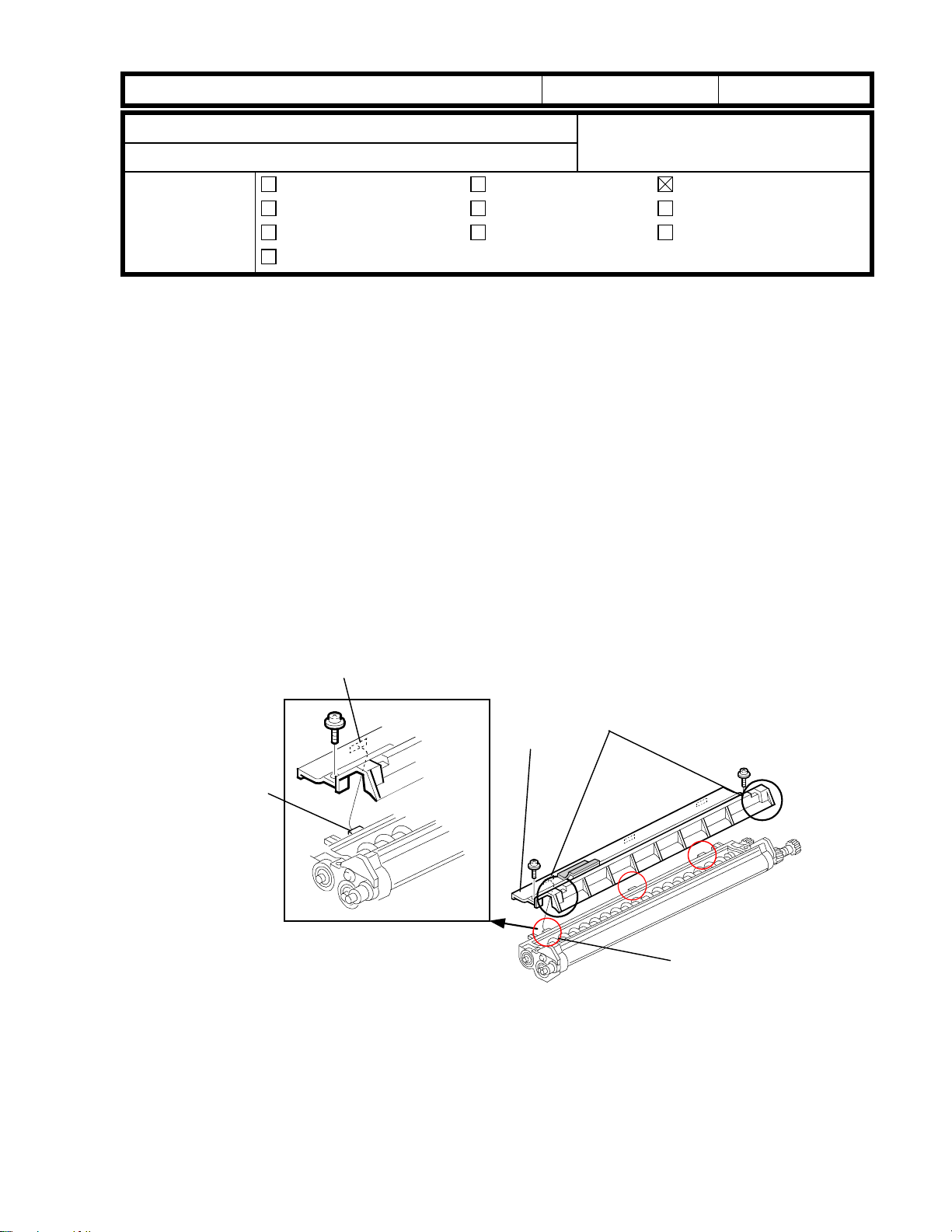
1. Remove the following parts:
2. Remove the 3 screws securing the
NOTE:
PSU and I/O board.
3. Disconnect the connector of the drum
4. Rotate the drum motor
5. Loosen the screw [G] and remove the
6. Remove the drum motor (4 screws)
7. Remove the 3 connectors from the
8. Remove the tension spring [I]. Then,
Iris/Lilac
Rear covers / Fly-wheel [A] / Stay [B]
PSU and the 4 screws securing the
I/O control board. Then, move these
two parts aside to make space to
remove the drum drive unit [C].
It is not necessary to remove the
motor [D].
counterclockwise manually so that the
screw [E] of the drum pulley [F] faces
downward.
tension spring [H].
and drum pulley (1 screw)
drive unit and remove the unit (4
screws and 2 stud screws).
remove the unit cover plate [J] (3
screws).
[A]
Date:
[D]
[B]
[I]
31-Dec-99
[C]
No.:
[G]
RA258016
[F]
[E]
[H]
NOTE:
(1) Before opening the drive unit, note the
routing of the timing belts as well as
the positioning of the pulleys.
This will make it much easier to put the
belts and pulleys back after the
procedure.
(2) Do not open the drive unit completely.
If this is done, the timing belt and
pulleys will come off the unit. Open the
cover just enough for gear replacement
(see the photo).
[J]
[K]
Page 40

RICOH Technical
Reissued: 15-Jan-00
Bulletin
PAGE: 9/8
Model:
9. Replace the white and black gears [K].
10. Reinstall the upper cover plate. Make
11. Reinstall the drive unit and drum
12. Reinstall the drum motor [D] (4
13. Connect the tension spring [E] and
Iris/Lilac
(The black gear is secured with 2
screws.)
sure that the heads [A] of the studs
are in position in the holes in the cover
plate.
NOTE:
[B] are properly set as shown.
pulley by pressing the timing belt [C]
down as shown.
screws).
rotate the motor
6 times. Secure the screw [F].
Make sure that the timing belts
counterclockwise
5-
Date:
31-Dec-99
[A]
No.:
[B]
RA258016
NOTE:
Before securing the screw, the motor
should be rotated after hooking the spring.
If this is not done, the proper tension will
not be applied to the belt, causing the
timing belt to jump during operation. This
may cause a partial color shift image.
14. Reinstall all other parts removed.
[C]
[D]
[F]
[E]
Page 41

RICOH Technical
Bulletin
PAGE: 1/3
Model:
Subject:
From:
Iris/Lilac
Curved dark bands / Uneven image density
Technical Service Dept., GTS Division
Classification:
Troubleshooting
Mechanical
Paper path
Other ( )
Date:
Prepared by:
Part information
Electrical
Transmit/receive
31-Dec-99
Action required
Service manual revision
Retrofit information
T. Itoh
No.:
RA258017
SYMPTOM
Curved dark bands [A] or uneven image
density appears due to a dirty charge
corona unit.
[A]
CAUSE
The charge corona fan stays on while the main switch is on. Since the charge corona fan
draws the air into the machine, the charge corona unit becomes dirty due to dust in the air.
The problem occurrence depends on the environmental conditions where the machine is
installed.
NOTE:
This problem has been reported only from the Ja panese market, so far. The
problem occurred especially in environments where a humidifier (supersonic wave
type) was used. A substance left after moisture evaporates adheres to the charge
corona unit, causing this problem.
SOLUTION
As a solution to this problem, two modifications have been applied. One involves SP mode
and the other is a grid cleaning pad. There are notes on how to apply the solution to the
field machines depending on the environment and/or the condition of the machine. Please
investigate which solution (either or both) should be applied.
Solution [1]: SP Mode
The software has been modified and the following SP mode was added.
SP No. Item
[Displayed]
03-980-00: Charge Corona Fan ON/OFF Timing Setting
03-980-00 MCFanCtrl 0 0: Stays on
Default Value Range Step SP7-
902/3
1: Turn off at
specific timing
Description
Specifies the off timing of the
charge corona fan.
When SP3-980-00 is set to “1”, the fan turns off 30 seconds after the drum motor stops or
when Energy Saver mode turns on. (The fan turns on again when the drum motor turns on
or when Energy Saver mode turns off.) This SP mode can extend the time until the charge
corona unit is considered dirty.
Page 42

RICOH Technical
Bulletin
PAGE: 2/3
Model:
This software change has been implemented in the main firmware (Ver. 6.621) on the
·
This software change has been implemented from the first mass production units on
·
NOTE:
When activating this SP mode, the transfer belt heater should be disconnected. This is
·
When activating this S P mode, please check the C/O (copies per origina l ) in full color
·
Solution [2]: Grid Cleaning Pad
Iris/Lilac
Iris. (This modification has been applied from the July production run.)
the Lilac.
Please read the following notes when changing the setting of this SP mode.
because the temperature inside the machine tends to increase since the charge
corona fan turns off at the timing explained above. (Please refer to the following page
for the procedure.)
copy mode. The output signal from the ID sensor tends to fluctuate due to temperature
changes inside machine. This may cause image the density to fluctuate if the C/O is
20 (20 repeat copies) or more.
Date:
31-Dec-99
No.:
RA258017
In addition to the SP mode, a grid cleaning pad (#A2592311) has been added to the upper
frame of the drum unit (as shown in the picture) from the June production run onward.
(Please refer to MB #18 for the Iris and #15 for the Lilac for the cut-in serial number.)
This modification enables service technicians or users to clean the grid plate. Please use
this pad if the problem is reported.
NOTE:
The grid cleaning pad tends to be worn away while cleaning the grid plate, and needs to
be replaced after being used for cleaning around 100 times. Although this is a consumable
part in this case, this part is not assigned as a PM part since the problem occurrence is
very rare.
Installation Procedure:
1. Using alcohol, clean the
The charge corona unit is normally secured with a screw. When asking users to
clean the charge corona unit, please remove the screw and instruct them to set
the charge corona unit properly after cleaning it. If the charge corona unit is not set
properly, this causes an SC301 or a blank image problem.
upper frame of the drum
unit where the grid cleaning
pad is attached.
2. Attach the cleaning pad [A]
as shown in the picture.
Page 43

RICOH Technical
Bulletin
PAGE: 3/3
Model:
Iris/Lilac
[B]
Date:
31-Dec-99
No.:
[A]
RA258017
1. Remove the lower rear cover.
2. Remove the used toner bottle (1 connector).
3. Remove the high voltage supply board -T2/ D [A] (1 screw and 2 connectors).
4. Disconnect the connector [B] of the heater located behind the high voltage supply
board.
Page 44

RICOH Technical
Bulletin
PAGE: 1/4
Model:
Subject:
From:
Classification:
Please correct your service manuals as follows:
1. Page 2-3 (5) ACC-Run-Time Process Control Self Check
Iris/Lilac models do not have this function, so please delete the explanation from your
service manual. This function is only used in the Cattleya.
2. Page 6-83 6.11.3 NV-RAM UPLOADING AND DOWNLOADING
Iris/Lilac
Service Manual
Technical Service Dept., GTS Division
Troubleshooting
Mechanical
Paper path
Other ( )
Part information
Electrical
Transmit/receive
Date:
29-Feb-00
Prepared by:
Action required
Service manual revision
Retrofit information
T. Itoh
No.:
RA258018
“With SP mode, copier settings can be uploaded to a Flash ROM card from the NVRAM inside the machine or downloaded from a flash ROM card to the NV-RAM.”
This explanation is wrong. When executing the upload or download with SP5-824 or 825,
uploading
downloading
No settings are uploaded or downloaded from the flash ROM card (IC card). The IC card
that contains the main program needs to be set in the main control board slot whenever
uploading or downloading.
transfers the data from the NVRAM to the flash ROM on the main board and
transfers the data from the flash ROM to the NVRAM.
Page 45

RICOH Technical
Bulletin
PAGE: 2/4
Model:
Iris/Lilac
Date:
29-Feb-00
No.:
RA258018
3. Appendix – 2 SP MODE TABLE
SP-5-114-000 Account color mode setup [Color Mode Selection : Key Card]
·
When the key counter has been installed or the user code mode has been enabled, it is
possible to select color mode(s) which are only accessible by using the key counter or
user code. The default setting for this SP mode is 15. This means that the key counter or
user code is always required whenever making copies.
Setting Black/White Single Color Twin Color Full Color
1 Counter
2 Counter
3 Counter Counter
4 Counter
5 Counter Counter
6 Counter Counter
7 Counter Counter Counter
8 Counter
9 Counter Counter
10 Counter Counter
11 Counter Counter Counter
12 Counter Counter
13 Counter Counter Counter
14 Counter Counter Counter
15 Counter Counter Counter Counter
Counter: A key counter or user code is required to make copies. The number is then
counted up by the key counter or the user code counter.
No mark: Copies can be made without a key counter or user code.
NOTE:
When SP-5-104-000 (A3/DLT double count) is set to 1 (double count), the mechanical total
counters and electrical counters on the operation panel count each copy/development
twice for A3/DLT. However, a key counter counts up only once. This is a specification
carried over from the Azalea.
Page 46

RICOH Technical
Bulletin
PAGE: 3/4
Model:
SP2-301 to 316 (except for SP2-311) - Belt transfer & Paper Transfer Bias
·
SP No. Default value in
02-301-01 1700 1700
02-301-02 1800 1800
02-301-03 1900 1900
02-301-04 2000 2000
02-301-05 1700 1700
02-301-06 1800 1800
02-301-07 1700 1700
02-301-08 1800 1800
02-301-09 1900 1900
02-301-10 1700 1700
02-301-11 1000 1700
02-301-12 1000 300
02-301-13 800 1000
02-301-14 900 1100
02-301-15 1000 1200
02-301-16 1100 1300
02-301-17 1200 1200
02-301-18 1300 1300
02-301-19 800 1100
02-301-20 900 1200
02-301-21 1000 1300
02-301-22 1200 1200
02-301-23 1700 1700
02-301-24 0 0
02-301-25 1700 1700
SP No. Default value in
02-313-01 100 100
02-313-02 100 100
02-313-03 200 200
02-313-04 250 250
02-313-05 100 100
02-313-06 100 100
02-313-07 100 250
02-313-08 100 300
02-313-09 100 100
02-313-10 100 100
02-313-11 200 270
02-313-12 100 270
Iris/Lilac
The default data described in the manual is incorrect. Please correct your manual.
The default value has been changed to the appropriate value in Ver. 6.43.
The default value has been changed for white lines on OHPs in Ver. 6.621.
The default value has been changed for white lines on OHPs in Ver. 6.621 (only for EU version).
Correct default
service manual
service manual
value
Correct default
value
Date:
SP No. Default value in
02-310-01 1 1
02-310-02 7 10
02-310-03 15 18
02-310-04 15 18
02-310-05 15 18
02-310-06 8 8
02-310-07 10 10
02-310-08 10 10
02-310-09 10 10
02-310-10 7 8
02-310-11 10 10
02-310-12 10 10
02-310-13 10 10
02-310-14 7 10
02-310-15 15 18
02-310-16 15 18
02-310-17 15 18
02-310-18 13 12
02-310-19 7 15
02-310-20 7 15
02-310-21 7 15
02-310-22 6 7
02-310-23 7 9
02-310-24 7 9
02-310-25 7 9
02-310-26 13 10
02-310-27 7 15
02-310-28 7 15
02-310-29 7 15
29-Feb-00
service manual
No.:
RA258018
Correct default
value
Page 47

RICOH Technical
Bulletin
PAGE: 4/4
Model:
SP No. Default value in
02-314-01 0 0
02-314-02 0 0
02-314-03 0 0
02-314-04 0 0
02-314-05 03
02-314-06 0 0
02-314-07 0 0
02-314-08 0 0
02-314-09 0 0
02-314-10 0 0
02-314-11 0 0
02-314-12 0 0
02-314-13 30
02-314-14 0 0
02-314-15 0 0
02-314-16 0 0
02-314-17 0 0
02-314-18 2 2
02-314-19 2 2
02-314-20 2 2
02-314-21 2 2
02-314-22 4 4
02-314-23 4 4
02-314-24 4 4
02-314-25 0 0
02-314-26 0 0
02-314-27 0 0
02-314-28 0 0
Iris/Lilac
service manual
Correct default
value
SP No. Default value in
02-315-01 3 -1
02-315-02 0 -1
02-315-03 0 -1
02-315-04 0 -1
02-315-05 0-1
02-315-06 0-1
02-315-07 0-1
02-315-08 0-1
02-315-09 0-1
02-315-10 0-1
02-315-11 0-1
02-315-12 0-1
02-315-13 3-1
02-315-14 0-1
02-315-15 0-1
02-315-16 0-1
02-315-17 0-1
02-315-18 0-1
02-315-19 0-1
02-315-20 0-1
02-315-21 0-1
02-315-22 0-1
02-315-23 0-1
02-315-24 0-1
02-315-25 0-1
02-315-26 0-1
02-315-27 0-1
02-315-28 0-1
Date:
29-Feb-00
service manual
No.:
RA258018
Correct default
value
SP No. Default value in
service manual
02-316-01 100 100
02-316-02 89 89
02-316-03 100 100
02-316-04 100 100
02-316-05 70 75
02-316-06 80 70
02-316-07 100 100
02-316-08 89 89
02-316-09 100 79
02-316-10 87 70
02-316-11 100 100
02-316-12 100 100
02-316-13 120 95
02-316-14 87 70
02-316-21 100 100
02-316-22 100 100
02-316-23 100 100
02-316-24 100 100
Correct default
value
02-316-25 100 125
02-316-26 100 100
02-316-27 100 100
02-316-28 100 100
02-316-29 100 100
02-316-30 100 100
02-316-31 100 100
02-316-32 100 100
02-316-33 100 100
02-316-34 100 100
Page 48

RICOH Technical
Bulletin
PAGE: 1/2
Model:
Subject:
From:
Classification:
Iris/Lilac
Squeaking noise
Technical Service Dept., GTS Division
Troubleshooting
Mechanical
Paper path
Other ( )
Date:
Prepared by:
Part information
Electrical
Transmit/receive
29-Feb-00
Action required
Service manual revision
Retrofit information
T. Itoh
No.:
RA258019
SYMPTOM
A squeaking noise is generated in the development unit.
CAUSE
The vibration generated from the doctor blade during the development process is
transferred to the upper cover. This results in a squeaking noise.
SOLUTION
To absorb the vibration, four foam rubber pads have been attached to the development
cover. If the squeaking noise occurs in the field machines, please follow the procedure
described below. Please refer to MB #22 (Iris) and #19 (Lilac) for the cut-in serial number
information.
1. Make a full color copy and check when
the noise occurs (i.e. at which color in
the development process).
2. Turn off the main switch.
3. Pull out the drawer unit.
4. Remove the drum unit and place a few
sheets of paper on the unit to prevent the
drum from developing light fatigue.
5. Remove the relevant development
unit(s).
6. Remove the development cover [A] (3
screws).
7. With damp and dry cloths, clean the
areas on the front and reverse sides of
the development cover where the pads
will be attached.
[A]
[B]
[C]
8. Attach 3 foam rubber pads [B] to the reverse side of the development cover as shown.
Page 49

RICOH Technical
Bulletin
PAGE: 2/2
Model:
9. Reinstall the development cover and attach one foam rubber pad [C] to the front side
10. Reassemble the machine.
Iris/Lilac
of the cover, as shown.
Date:
29-Feb-00
No.:
RA258019
Page 50

!"#$% T
echnical Bulletin
PAGE: 1/2
Model:
Subject:
From:
Iris/Lilac
Bypass Tray Modificaition
Technical Services Dept., GTS Division
Classification:
Troubleshooting
Mechanical
Paper path
Other ( )
Part information
Electrical
Transmit/receive
Date:
06-Apr-00
Prepared by:
No.:
RA258020
T. Itoh
Action required
Service manual revision
Retrofit information
SYMPTOM
Paper jam at the by-pass tray.
CAUSE
Even if the user selects ‘sideways’ with the operation panel, the paper orientation is
automatically reset to ‘lengthwise’ if the by-pass tray side fences are moved to the 12” size
position. This may result in a paper jam.
SOLUTION
A stopper has been added to the front side fence so that the maximum width that can be
set is A3 (11”). This stopper can be pulled out to make copies with paper larger than this
size.
• Please refer to MBs, which will be issued soon, for the cut-in serial number.
• An errata sheet (see the next page) has been enclosed with the modified production
units. An English version is enclosed with North American models and 5 languages are
enclosed with Europe/Asia models.
To add the stopper [A], the shape of the front side fence [B] was modified. Please refer to
the next page.
New parts:
#A2592972: Front Side Fence
#A2592973: Side Fence Stopper
NOTE: The part number of the by-pass feed table assembly has not changed, but the
suffix has. Therefore, please order the above two parts separately to apply the
modification in the field.
Page 51

!"#$% T
echnical Bulletin
PAGE: 2/2
Model:
Iris/Lilac
Date:
06-Apr-00
No.:
RA258020
Errata Sheet:
NOTE: This sheet is for Europe/Asia versions. For the North America version, the paper
size indicated is 11”x17”, not A3.
[B]
[A]
Page 52

!"#$% T
echnical Bulletin
PAGE: 1/2
Model:
Subject:
From:
Iris/Lilac
Dust Filter
Technical Services Dept., GTS Division
Classification:
Troubleshooting
Mechanical
Paper path
Other ( )
Part information
Electrical
Transmit/receive
Date:
22-Jun-00
Prepared by:
No.:
RA258021
T. Itoh
Action required
Service manual revision
Retrofit information
The dust filter has been modified twice. This RTB explains the modification history and
some notes for servicing in the field.
1st Modification (Refer to MB #21 for Iris and #18 for Lilac.)
Old part
number
A2591082 A2591047 Dust Filter 1-1 X/O See Note 1.
New part
number
Description Q’ty Int Remarks
NOTE 1:
The material of the filter has been modified to minimize the amount of dust exiting the
machine.
2nd Modification (Refer to MB #28 for Iris and #24 for Lilac.)
Old part
number
A2591081 AA010109 Ozone Filter 1 – 1 X/O
A2591047 A2592337 Dust Filter 1 – 3 X/X
A2591083 Ozone Filter Case
A2591085 Case Cover – Ozone Filter
A2591317 Duct Seal – Lower Case 1 - 0 See Note 4.
New part
Description Q’ty Int Remarks
number
A2592334 Ozone Filter Case 1 – 1 X/X
A2592335 Upper Case Cover 1 – 1 X/X
A2592336 Front Case Cover 0 – 1
A2592338 Seal – 5x36 0 – 1
A2592339 Seal – 5x76 0 – 2
See Note 2-1 to
2-3 and Note 3.
X/O
NOTE 2-1:
The number of filters was increased from 1 to 3 to further minimize the amount of dust
exiting the machine.
Page 53

!"#$% T
echnical Bulletin
PAGE: 2/2
Model:
Iris/Lilac
[E]
[B]
[D]
[C]
[C]
Date:
22-Jun-00
[A]
No.:
RA258021
NOTE 2-2:
If the MIF do not show any toner scattering at PM visits, you only need to replace the
filter(s) which are dirty with toner and/or dust. The filters become dirty from the joint duct
side [A]. Therefore, please remove the dirty filter(s) [B] first, then shift the clean filter(s) [C]
toward the joint duct side. Then, insert the new filter(s) [D] as shown in the illustration. The
filters should always be installed so that the side with the tab [E] faces the joint duct [A].
NOTE 2-3:
The old filter A2591047 will continue to be available as a service part.
NOTE 3:
A2591083 and A2591085 are no longer available as service parts. If either of them needs
to be replaced in the field, please replace both with the 6 parts listed in the table
(A2592334 – 9).
NOTE 4:
The duct seal attached to the rear cover is no longer necessary. Therefore, this part has
been removed.
Page 54

echnical Bulletin
T
PAGE: 1/1
Model:
Subject:
From:
Iris/Lilac
Transfer belt stay installation procedure
Technical Services Dept., GTS Division
Classification:
Troubleshooting
Mechanical
Paper path
Other ( )
Part information
Electrical
Transmit/receive
Date:
22-Jun-00
Prepared by:
No.:
RA258022
T. Itoh
Action required
Service manual revision
Retrofit information
Please note the remarks explained below when installing the transfer belt stay [A].
REMARKS:
Install the transfer belt stay [A] while pressing portion [B]. The transfer belt unit will then be
secured in the proper position by the pressure from spring [C]. If portion [B] is not pressed
while the screws are fastened, the transfer belt stay will not be fixed in the proper position
due to the pressure from the spring. This will cause the PG (photoconductor gap) to shift
slightly.
Although a slightly shifted PG would not directly cause any machine failure, a proper PG is
essential to ensure the effectiveness of measures such as troubleshooting for black toner
scattering (PG seals). Please be sure to follow the above procedure when installing the
transfer belt stay.
NOTE: The screws can be fastened in any order.
[B]
[A]
[C]
Page 55

!"#$% T
echnical Bulletin
PAGE: 1/3
Model:
Subject:
From:
Iris/Lilac
Toner scattering inside machine (Toner Hopper Area)
Technical Services Dept., GTS Division
Classification:
Troubleshooting
Mechanical
Paper path
Other ( )
Part information
Electrical
Transmit/receive
Date:
22-Jun-00
Prepared by:
No.:
RA258023
T. Itoh
Action required
Service manual revision
Retrofit information
SYMPTOM
Toner scatters around the toner hopper area and inside the machine.
CAUSE
The toner hopper seal is damaged or peeled off while the toner bottle is replaced. Toner
spills out from the gap between the toner hopper seal and the toner supply opening of the
toner bottle.
SOLUTION
Protective sheets [A] have been added to the toner hopper seals [B], in order to prevent
the toner hopper seal from being damaged while the toner bottle is replaced.
[B]
[A]
Page 56

!"#$% T
echnical Bulletin
PAGE: 2/3
Model:
INSTALLATION PROCEDURE
Iris/Lilac
[A]
[F]
[E]
Date:
22-Jun-00
[B]
[C]
No.:
RA258023
OK
[D]
1. Pull out the drawer unit.
2. Remove the drum unit and place a few sheets of paper on the unit to prevent the drum
from developing light fatigue. Then, remove the toner bottle.
3. Rotate the drawer unit so that the toner supply opening [A] faces up, then lock the
position of the revolver unit by putting a cleaning cloth [B] in between the drawer unit
and the development unit as shown.
4. Remove the stay [C] (2 screws and 1 connector).
5. Clean the area around the toner hopper seal [D] with a dry cloth.
NOTE: Do not use alcohol. Thoroughly clean the area where the protective seal [E] is to
be attached. If the toner hopper seal is already damaged or peeled off, please
replace the seal.
6. Fold the protective sheet [E] along the dotted line and attach it to the hopper as shown.
(Refer to the picture on the next page.)
NOTE: Make sure that the protective sheet is properly attached, without any gap. If this is
not done, the sheet may peel off when the toner bottle is replaced.
NG
7. Attach the portion [F] of the seal along with the hopper and fold the end of seal and
attach it as shown
Page 57

!"#$% T
echnical Bulletin
PAGE: 3/3
Model:
8. Attach a piece of tape [A] to the toner supply opening before rotating the revolver so that
toner will not spill out from the hopper. Turn the revolver to the setting position; then
remove the tape [A] and insert the bottle.
Iris/Lilac
Date:
22-Jun-00
No.:
[A]
RA258023
9. Attach the protective sheets for the other colors.
Page 58

!"#$% T
echnical Bulletin
PAGE: 1/2
Model:
Subject:
From:
Iris/Lilac
Toner spiling over
Technical Service Dept., GTS Division
Classification:
Troubleshooting
Mechanical
Paper path
Other ( )
Part information
Electrical
Transmit/receive
Date:
22-Jun-00
Prepared by:
No.:
RA258024
T. Itoh
Action required
Service manual revision
Retrofit information
SYMPTOM
Toner spills out from the joint section [A] of the toner collection coil, and the interior of the
machine at the rear becomes dirty with toner. This can cause toner spots on copies or
paper jams if toner drops onto the clutches.
CAUSE
Used toner tends to lump together due to the temperature of the toner collection coil. The
toner then gets clogged around the joint section. This can cause toner to spill out from the
joint section.
SOLUTION
• The material of the toner collection coil has been changed from plastic to metal. This
will prevent the temperature of the coil from rising. This modification was applied to the
production line in July ’99. Please refer to MB #05 (Iris) and #02 (Lilac) for the cut-in
serial numbers. At the same time, in order to force the toner to drop straight down into
the collection coil tube, the size of cutout [B] in the toner outlet cap has been changed
as shown below.
• A seal has been added to the drawer unit to cover the joint section. This was applied to
the production line in February 2000. Please refer to MB #29 (Iris) and #25 (Lilac) for
the cut-in serial numbers.
If this problem occurs in the field, please replace the toner collection coil and toner outlet
cap, and attach the seal.
• Toner collection coil P/N: #A2593631
• Toner outlet cap P/N: #A2593582
• Seal 14x37 P/N: #A2592396
NOTE: Part number #A2593582 has not
been changed. However, the P/N
suffix has been changed.
[B]
[B]
[A]
Page 59

!"#$% T
echnical Bulletin
PAGE: 2/2
Model:
Replacement Procedure
1. Pull out the drawer unit.
2. Remove the drum unit and place a few sheets of paper on the unit to prevent the drum
Iris/Lilac
[A]
0 to 1.5 mm
[B]
1 to 2.5 mm
from developing light fatigue.
Date:
[C]
22-Jun-00
[D]
No.:
RA258024
[F]
[E]
3. With alcohol, clean the area where the seal [A] is to be attached.
4. Attach the seal [A] to the drawer unit as shown.
5. Remove the cleaning unit from the drum unit.
NOTE: Make sure that the drum is protected from light.
6. Remove the toner outlet cap [B] (1 screw) and spring [C].
7. Replace the toner outlet cap and toner collection coil [D] (snap-ring [E] and gear [F]).
8. Reassemble the machine.
Page 60

echnical Bulletin
T
PAGE: 1/7
Model:
Subject:
From:
Iris/Lilac
SC385 / Bk toner scattering inside machine
Technical Services Dept., GTS Division
Classification:
Troubleshooting
Mechanical
Paper path
Other ( )
Part information
Electrical
Transmit/receive
Date:
22-Jun-00
Prepared by:
No.:
RA258025
T. Itoh
Action required
Service manual revision
Retrofit information
SYMPTOM
Black toner scatters inside the machine. Toner accumulates around the black development
unit and ID sensor areas, which can sometimes cause SC385.
CAUSE
If the PG (photoconductor gap) is close to the upper limit, toner concentration tends to
increase and toner may scatter inside the machine. When toner accumulates on the ID
sensor, this may cause SC385.
This occurs most often with black toner due to its unique characteristics.
SOLUTION
Production line
• In order to shift the PG, a PG seal (#A2593219) has been attached to the lower
development unit holder of the black development unit only. Please refer to MB #27 for
Iris and #23 for Lilac.
NOTE: Please do not attach the PG seals for the color development units. If this is done,
a color band may appear on the outputs. This is because the narrow PG may
cause the developer sleeve of a color development unit to touch the drum surface
when the unit moves into the development position.
• The dust filter has been modified twice to minimize the amount of dust exiting the
machine. For the first modification, refer to MB #21 (Iris) and #18 (Lilac). For the
second, refer to MB #28 (Iris) and #24 (Lilac).
• The ID sensor cover has been modified to optimize the airflow to the ID sensor. This
prevents toner from accumulating on the surface of the ID sensor. Please refer to MB
#32 (Iris) and #28 (Lilac).
• The drum shaft supporter has been modified and an additional ball bearing has been
inserted in order to prevent the PG from changing during copy runs. Please refer to MB
#34 (Iris) and #30 (Lilac).
• The development unit holder has been modified twice. The first modification was done
to improve the holder durability and the second was done to ensure the proper PG.
Please refer to MB #33 (Iris) and #29 (Lilac).
Page 61

echnical Bulletin
T
PAGE: 2/7
Model:
Iris/Lilac
Date:
22-Jun-00
No.:
RA258025
Cut-in Serial Numbers:
Development unit holderPG seal ID sensor cover Drum shaft
supporter
Iris
A258-15 3B39100001 3B30040001 3B30050001 3B30030001 3B30050001
A258-17 H01910XXXXX H0100400001 H0100500001 H0100300001 H0100500001
A258-19 H01910XXXXX H01004XXXXX H0100500066 H0100300086 H0100500066
A258-22 AY7910XXXX AY70030345 AY70050001 AY70030008 AY70050001
A258-26 3S51090001 3S50400001 3S50500001 3S50400001 3S50500001
A258-27 H0191000321 H0100400101 H0100500081 H0100400101 H0100500081
A258-29 H0191000376 H0100400286 H0100500284 H0100300308 H0100500284
A258-55 L036910XXXX L0360040001 L0360050001 L0360040001 L0360050001
A258-65 L036910XXXX L0360040023 L0360060031 L0360040023 L0360060031
Lilac – Basic
A259-15 3B4910XXXXX 3B40040001 3B40050001 3B40030001 3B40050001
A259-17 H02910XXXXX H0200400001 H0200500001 H0200300001 H0200500001
A259-22 AY99100001 AY90040001 AY90050001 AY90040001 AY90050001
A259-26 3S61090001 3S60400001 3S60500001 3S60400001 3S60500001
A259-27 H0291000001 H0200400201 H0200500251 H0200400201 H0200500251
A259-29 H0291000033 H02004XXXXX H0200500357 H02004XXXXX H0200500357
A259-55 L037910XXXX L037004XXXX L037005XXXX L037004XXXX L03705XXXX
A259-65 L037910XXXX L0370040001 L0370060001 L0370040001 L0370060001
Lilac – Edit
A260-15 3B59100001 3B50040001 3B50050001 3B50030001 3B50050001
A260-17 H0391000001 H0300300094 H0300500001 H0300300001 H0300500001
A260-22 AZ19100001 AZ10040001 AZ10050001 AZ10040001 AZ10050001
A260-26 3S71090001 3S7040XXXX 3S70500001 3S7040XXXX 3S70500001
A260-27 H03910XXXXX H0300400038 H0300500028 H0300400038 H0300500028
A260-29 H0391000026 H0300400089 H0300500040 H0300400089 H0300500040
A260-55 L038910XXXX L0380040001 L0380050001 L0380040001 L0380050001
A260-65 L038910XXXX L038004XXXX L038005XXXX L038004XXXX L038005XXXX
A2593229 ->
B0173229
B0173229 ->
A2593240
Page 62

echnical Bulletin
T
PAGE: 3/7
Model:
In the field
The following parts need to be replaced or attached:
• Replace the drum shaft supporter.
• Attach PG seals to the lower development unit holders.
• Replace the development unit holders.
• Replace the ID sensor cover.
• Replace the dust filter.
Please refer to the following procedures for replacement or attachment.
1. Drum shaft supporter replacement
Iris/Lilac
[A]
Date:
22-Jun-00
No.:
RA258025
[C]
[B]
[A]
Old P/N New P/N Description Page Index
A2592462 A2592422 Front Supporter – Drum Shaft 49 (Iris)
45 (Lilac)
1. Remove the drum stay [A] (5 screws).
2. Replace the drum shaft supporter [B] (4 screws).
NOTE: When reinstalling the drum stay [A], the screws should be secured while pressing
portion [C] of the drum stay. Refer to RTB #22 for details.
1
Page 63

echnical Bulletin
T
PAGE: 4/7
Model:
Iris/Lilac
Date:
22-Jun-00
No.:
2. PG seal attachment & development unit holder replacement procedure
[B]
[A]
6+/- 1 mm
Old P/N New P/N Description Page Index Remarks
- A2593219 Seal 7x10 39 (Iris)
35 (Lilac)
A2593229 A2593240 Development Unit Holder 39 (Iris)
35 (Lilac)
#13 See note.
1 See note.
RA258025
NOTE: The PG seal size has been changed from 10x14 mm to 7x10 mm to achieve the
target PG. The part number was not changed through this modification, but the
suffix was.
NOTE: The development unit holder has been modified twice. The above part number is
the latest one (A2593229 -> B0173229 -> A2593240).
1. Pull out the drawer unit.
2. Remove the drum unit and place a few sheets of paper on the unit to prevent the drum
from developing light fatigue.
3. Clean the machine using a vacuum cleaner.
4. Remove the black development unit.
5. Clean the lower development unit holder [A] completely with damp and dry cloths.
NOTE: For damp cloths, use water and not alcohol. Alcohol can deform the seal. If alcohol
is used by accident, clean the holder with a dry cloth after the holder dries.
6. Attach a PG seal [B] to both sides of the lower development unit holder as shown.
NOTE: Make sure that the seal has been attached flush against the holder and is not
folded. If the seal is not properly attached, the PG will be out of specification.
The PG seal should not be attached to the development holders for other colors. If
this is done, the PG will become narrow and the developer brush may contact the
drum while the revolver rotates. This causes a color band to appear on the
outputs.
Page 64

echnical Bulletin
T
PAGE: 5/7
Model:
Iris/Lilac
[A]
[D]
[C]
Date:
22-Jun-00
[B]
[C]
No.:
RA258025
[B]
7. Reinstall the development unit and install the new development unit holders [A].
NOTE: If there is a foam rubber pad already attached to the development cover [C], be
sure to remove it before installing the development unit. If the unit is installed with
the foam rubber pad attached, the unit will be pressed by the toner cartridge case
[D], causing the PG to become narrower.
Page 65

echnical Bulletin
T
PAGE: 6/7
Model:
3. ID sensor cover replacement
[A]
Iris/Lilac
[B]
Date:
22-Jun-00
[D]
No.:
RA258025
[C]
Old P/N New P/N Description Page Index
A2592475 A2592468 ID Sensor Cover 51 (Iris)
47(Lilac)
1. Loosen the screw [A] securing the charge corona fan.
2. Remove the ID sensor cover [B] (2 screws).
3. Install the new ID sensor cover (2 screws).
NOTE: Make sure that the mylar [C] is in the proper position between the ID sensor cover
and lower stay [D] as shown.
11
Page 66

echnical Bulletin
T
PAGE: 7/7
Model:
4. Dust filter replacement
Iris/Lilac
[A]
[B]
Old P/N New P/N Description Page Index
A2591082 A2591047 Dust Filter 81 (Iris)
Date:
85 (Lilac)
22-Jun-00
12
No.:
RA258025
1. Remove the cover [A] (3 screws).
2. Replace the main exhaust fan filter [B].
5. After reassembling the machine
1. If toner has scattered inside the machine, the toner concentration might already be too
high. Therefore, please make 5 black-and-white copies in the following mode to reduce
the toner concentration.
• Set SP5-955-018 to 6 (solid test pattern). Make sure that SP 5-955-017
(LD_PWM) is set to the default (128).
• Select A3 (DLT) size.
Page 67

echnical Bulletin
T
PAGE: 1/20
Model:
Subject:
From:
Iris/Lilac
Firmware Modification History
Technical Services Dept., GTS Division
Classification:
Troubleshooting
Mechanical
Paper path
Other ( )
Part information
Electrical
Transmit/receive
Date:
13-Oct-00
Prepared by:
No.:
RA258026
T. Itoh
Action required
Service manual revision
Retrofit information
This RTB will explain the firmware modification history for Iris/Lilac.
As shown in the table below, both the main and scanner firmware differ from product to product.
This is why this RTB has been arranged slightly differently than usual (please see the Table of
Contents below). The tables on the following page show the display languages available for each
firmware.
Development Name Product Code Main Firmware Scanner Firmware
Iris A258 Unique for Iris
Lilac – Basic A259
Lilac – Edit A260
Unique for Lilac
Common for Iris and Lilac – Basic
Unique for Lilac – Edit
TABLE OF CONTENTS
1. MAIN FIRMWARE FOR IRIS
1.1 Modification History 2
1.2 Contents of Modification 5
2. MAIN FIRMWARE FOR LILAC
2.1 Modification History 9
2.2 Contents of Modification 10
3. SCANNER FIRMWARE
3.1 Modification History 13
3.2 Contents of Modification
3.2.1 Iris & Lilac – Basic 14
3.2.2 Lilac – Edit 15
4. CUT-IN SERIAL NUMBER INFORMATION
4.1 Main Firmware
4.1.1 Iris 16
4.1.2 Lilac 17
Page
4.2 Scanner Firmware
4.2.1 Iris & Lilac – Basic 18
4.2.2 Lilac – Edit 19
Appendix 1 New SP mode (SP2-203 and 204):
ID sensor development potential 20
Page 68

echnical Bulletin
T
PAGE: 2/20
Model:
Iris/Lilac
Display languages available for each firmware:
For Iris:
Type P/N Model Code
(A258-)
1 NA A2585197 15, 17, 55
2 EU A2585198 22, 26, 27, 29, 65
3 TWN A2585199 19
4 EU2 A2585181 Language software
5 EU3 A2585182 Language software
6 EU4 A2585183 Language software
English
English
Chinese
Spanish
English
English
For Lilac:
Type P/N Model Code
(A259/A260-)
1 NA A2605197 15, 17, 55
2 EU A2605198 22, 26, 27, 29, 65
English
English
Date:
French Spanish Brazilian -
French German Italian -
English - - -
Dutch Danish Swedish -
Portuguese Norwegian Czech Polish
Russian - - -
French Spanish Brazilian -
French German Italian -
13-Oct-00
Language
Language
No.:
RA258026
3 EU2 A2605181 Language software
4 EU3 A2605182 Language software
Spanish
English
Dutch Danish Swedish -
Portuguese Norwegian Czech Polish
• Languages in boldface are default.
1. MAIN FIRMWARE FOR IRIS
1.1. Modification History
For the USA Model (NA)
Suffix File No.
A2585197 Version C.SUM Production
B - 6.13A - 1st Mass Prod.
C A2585197cv615 6.15 F3E2
D A2585197dv643 6.43 FAC2
E A2585197ev6431 6.431 E813
F A2585197f 6_621na 6.621NA 025C
G A2585197g 6_81na 6.81NA 28BD
H A2585197h 6_91na 6.91NA 58F3
J A2585197j 6_913na 6.913NA B591
K A2585197k v7_02na 7.02NA 29C4
L - 7.04NA -
M A2585197M 7.05NA 88FF
Refer to Section 4.
Page 69

echnical Bulletin
T
PAGE: 3/20
Model:
Iris/Lilac
Date:
13-Oct-00
No.:
RA258026
For the European Model (EU)
Suffix File No.
Version C.SUM Production
A2585197B - 6.13A - 1st Mass Prod.
C A2585197cv615 6.15 F3E2
D A2585197dv643 6.43 FAC2
E A2585197ev6431 6.431 E813
A2585198 A2585198 v6_621eu 6.621EU D9A3
A A2585198a v6_81eu 6.81EU D282
B A2585198b v6_91eu 6.91EU DBA0
C A2585198c v6_913eu 6.913EU 1D4A
D A2585198d v7_02eu 7.02EU F355
E - 7.04EU F A2585198F 7.05EU 528F
Refer to Section 4.
For the Asia Version (TWN)
Suffix File No.
A2585199 Version C.SUM Production
- A2585199 v6_81twn 6.81TWN 1BF6
A A2585199a v6_91twn 6.91TWN 2E87
B A2585199b v6_913twn 6.913TWN 7548
C A2585199c v7_02twn 7.02TWN D441
D - 7.04TWM -
E A2585199E 7.05TWN 3D02
Refer to Section 4.
For European 2nd Language (EU2)
Suffix File No.
A2585181 Version C.SUM
- A2585181 v6_621eu2 6.621EU2 841B
A A2585181a v6_81eu2 6.81EU2 97C1
B A2585181b v6_91eu2 6.91EU2 BD9E
C A2585181c v6_913eu2 6.913EU2 57EB
D A2585181d v7_02eu2 7.02EU2 1067
E - 7.02EU2 F A2585181F 7.03EU2 8957
For European 3rd Language (EU3)
Suffix File No.
A2585182 Version C.SUM
- A2585182 v6_621eu3 6.621EU3 74BF
A A2585182a v6_81eu3 6.81EU3 4EFF
B A2585182b v6_91eu3 6.91EU3 DCBC
C A2585182c v6_913eu3 6.913EU3 A7B3
D A2585182d v7_02eu3 7.02EU3 D746
E - 7.04EU3 F A2585182F 7.05EU3 01CD
Page 70

echnical Bulletin
T
PAGE: 4/20
Model:
For European 4th Language (EU4)
Iris/Lilac
Suffix File No.
A2585183 Version C.SUM
- A2585183 v6_81eu4 6.81EU4 CD85
A A2585183a v6_91eu4 6.91EU4 CB04
B A2585183b v6_913eu4 6.913EU4 67A4
C A2585183c v7_02eu4 7.02EU4 954E
D - 7.04EU4 -
E A2585183E 7.05EU4 2A48
Date:
13-Oct-00
No.:
RA258026
Page 71

echnical Bulletin
T
PAGE: 5/20
Model:
Iris/Lilac
Date:
13-Oct-00
No.:
RA258026
1.2. Modifications
Version Modifications Remarks
6.13A
6.15
6.43
6.431
6.621
- This version of the main firmware has been used from the first unit of mass
production.
1 Allows the counter method to be changed (copy or development counter)
only once in SP mode (SP7-008-000).
1 The transfer belt bias has been optimized as follows:
SP Mode Number Current value New value
SP2-301-013 800V 1000V
SP2-301-014 900V 1100V
SP2-301-015 1000V 1200V
SP2-301-016 1100V 1300V
SP2-301-019 800V 1100V
SP2-301-020 900V 1200V
SP2-301-021 1000V 1300V
2 The following problem has been fixed:
In a certain situation, the last original may not be fed out from the ARDF in 1
to 1 mode.
1 To prevent Toner End from being detected by mistake for black toner, the
detection parameter has been changed from 4 to 8 times.
The display for the counters has been changed. “Copies” or “Developments”
1
is displayed on the panel, depending on the counter method selected.
This allows us to clearly know which counter method has been selected.
2 Symptom
Horizontal white lines / dirty background at the trailing edge when copying
onto transparencies. This occurs in all environmental conditions except high
temperature and humidity.
Solution
The default setting of the following SP mode has been changed and the AC
component of the paper separation corona turns ON when copying onto
transparencies.
SP Mode No. Current Setting New Setting
SP2-310-10 10 uA 8 uA
SP2-316-5 70% 75%
SP2-316-6 80% 70%
SP2-316-25 100% 125%
3 During evaluation tests on European paper, white lines appeared in halftone
areas. To prevent this problem, the settings of the following SP modes have
been changed (for European versions only):
SP mode No. Current setting New setting
SP2-316-009 100% 79%
SP2-316-010 87% 70%
SP2-316-013 120% 95%
SP2-316-014 87% 70%
Page 72

echnical Bulletin
T
PAGE: 6/20
Model:
Iris/Lilac
Date:
13-Oct-00
No.:
RA258026
Version Modifications Remarks
4 The shutdown timing for the main exhaust fan has been changed as follows
to reduce the machine noise level. These figures refer to how long the
machine waits to turn off the fan after turning off the drum motor.
Before After
30 seconds 5 seconds
6.81
6.91
6.913
5 To prevent the charge corona unit from becoming dirty too soon, the
following SP mode has been added.
SP3-980-000 “Charge corona fan ON/OFF timing setting”
6 The following problem was corrected:
The logging data (SP7-809-01) was not counted properly.
1 The following problem was fixed:
An area of up to 20 mm from the trailing edge of the last copy becomes
lighter in OHP or Thick Paper mode under the following conditions:
• Selected paper size is A4(LT) sideways or smaller
• The amount of copies selected is an even number.
2 The following problem was fixed:
In Series copy mode (Book to one-sided), halftone areas on the right side of
originals come out lighter under the following conditions.
• Black-and-white copy mode
• The number of copies selected is 3 or more.
3 After a job is finished, the Start Key will turn green sooner.
1 This firmware can support the coin-lock system.
NOTE:
It is not possible to use both the coin-lock system and User Code mode at
the same time.
1 A blank display problem found in the previous version has been corrected.
2 To prevent by-pass tray jams when feeding the reverse side of the paper,
the pick-up roller OFF timing has been changed.
With this modification, the pick-up roller continues to feed the paper until the
paper reaches the grip roller.
Refer to RTB #017 for
the details.
Do not use this version
in the field. This
firmware causes the
control panel of the
controller to appear
blank.
Page 73

echnical Bulletin
T
PAGE: 7/20
Model:
Iris/Lilac
Date:
13-Oct-00
No.:
RA258026
Version Modifications Remarks
7.02
1 The software has been modified for the following reasons:
• To minimize dirty background in normal paper copy/print modes
• To minimize dirty background in OHP/thick paper copy/print modes
• To prevent horizontal color bands in color copy/print modes
- Contents of modification -
(1) Dirty background
The development unit will stay at the development position under the
following conditions:
• When the OPC drum starts rotating to develop the latent image.
• During the extra transfer belt rotation (see the note below) in Thick/OHP
mode (copy/print).
To prevent toner from being attracted to the drum, a development bias is
applied to the development sleeve. However, the dirty background becomes
worse if the drum and/or developer have deteriorated. To minimize dirty
background, the timing of the revolver rotation and the position of the
development unit have been changed.
Note:
In Thick Paper/OHP Modes, the process speed is reduced by half after the
image is developed on the transfer belt (4-color image for full color). To
properly transfer the image developed on the transfer belt onto the sheet of
paper, the transfer belt makes an extra rotation.
7.04
7.05
(2) Horizontal color band
To improve image quality, the PG was slightly reduced from March ’00
production. However, when the PG is reduced, the developer brush tends to
touch the drum surface while the revolver rotates. This may result in a
horizontal color band on the outputs. To prevent this band, the timing of the
revolver rotation has been changed so that the color band will not be
transferred to the image area of the transfer belt.
2 The SP modes listed below have been added so that toner concentration
can be adjusted with more precision and finer control.
New SP modes: SP2-203-001 to 013 and SP2-204-001 to 012
(Please refer to Appendix 1 for details).
3 The software has been changed so that the key counter counts twice for
A3/DLT when SP5-104-000 is activated (A3/DLT Double Count).
1 To prevent any data changes due to electrical noise, the initialization method
of the NVRAM has been changed.
1 “Charge Corona Fan ON/OFF” has been added to SP mode (refer to RTB
RA258017 for details). However, since turning off the fan can cause the
temperature inside machine to increase, setting “2” below (bold) has been
newly added to the software.
0: Stays on
1: Turn off
2: Turn on at 30
* using the temp. measured by the temp/humidity sensor
o
C, turn off at 26oC
Page 74

echnical Bulletin
T
PAGE: 8/20
Model:
Iris/Lilac
Date:
13-Oct-00
No.:
RA258026
Version Modifications Remarks
2 If the machine is continuously on, the machine will not do the initial process
control self-check, causing the toner concentration to be out of range. To
achieve optimum image quality under this condition, the software has been
changed so that the initial process control self check will be done if both of
the following conditions are met:
• 12 hours has passed since the last initial process control or forced
process control self-check and
• 1 hour has passed since the last timed process control self-check.
3 When the revolver rotates, a small amount of toner can flow into the
development unit, causing the toner concentration to increase.
During the initial process control self-check, the machine automatically
corrects the toner concentration (Toner Density Auto Control); however, this
does not happen unless the main switch is turned off and on. To work
around this, the software has been modified so that the toner density auto
control can be done during the interval process control self-check. The
corresponding setting (2) has been added to SP3-128:
SP3-128 Toner Density Auto Control
Setting (Default : 0)
0: Execute at initial and forced process control self-check
1: Not execute at any self-check
2: Execute at initial, forced, and interval process control self-check
The following SP modes have been newly added for Toner Density Auto
Control:
SP3-130: TD Auto Correction Setting
Specifies the number of copies to consume toner for the toner density
correction of the initial or interval process control self-check.
NOTE: Normally, it is not necessary to adjust this SP mode in the field.
[Adjustable range / Default /Step]
SP3-130-001 Initial self-check [0 to 50 copies / 10 / 1 step]
SP3-130-002 Interval self-check [0 to 50 copies/ 5 /1 step]
SP3-130-003 Table limit setting [0 or 1 / 0 ]
0: Limit, 1: No limit
Page 75

echnical Bulletin
T
PAGE: 9/20
Model:
Iris/Lilac
Date:
13-Oct-00
No.:
RA258026
2. MAIN FIRMWARE FOR LILAC
2.1 Modification History
For the USA Model (NA)
Suffix File No.
A2605197 Version C.SUM Production
B a2605197b v1_694na 1.694NA 8784 1st Mass Prod.
C a2605197c v1_728na 1.728NA 877A
D a2605197d v1_734na 1.734NA 9027
E a2605197e v1_735na 1.735NA D3C0
F A2605197f v1_771na 1.771NA C8F9
G - 1.774NA H - 1.777NA -
J A2605197J 1.778NA 4F37
For the European Model (EU)
Suffix File No.
A2605198 Version C.SUM Production
A a2605198a v1_694eu 1.694EU 46D3 1st Mass Prod.
B a2605198b v1_728eu 1.728EU 28CD
C a2605198c v1_734eu 1.734EU A28C
D a2605198d v1_735eu 1.735EU 33D6
E A2605198e v1_771eu 1.771EU 83B1
F - 1.774EU G - 1.777EU H A2605198H 1.778EU 873B
Refer to Section 4.
Refer to Section 4.
For European 2nd Language (EU2)
Suffix File No.
A2605181 Version C.SUM
- A2605181 v1_713eu2 1.713EU2 7B4E
A A2605181a v1_728eu2 1.728EU2 91C2
B A2605181b v1_734eu2 1.734EU2 1A4B
C A2605181c v1_735eu2 1.735EU2 BB65
D A2605181d v1_771Eeu2 1.771EU2 E291
E - 1.774EU2 F - 1.777EU2 -
G A2605181G 1.778EU2 18B8
For European 3rd Language (EU3)
Suffix File No.
A2605182 Version C.SUM
A A2605182a v1_734eu3 1.734EU3 27A4
B A2605182b v1_735eu3 1.735EU3 5593
C A2605182c v1_771eu3 1.771EU3 15B4
D - 1.774EU3 -
E - 1.777EU3 F A2605182F 1.778EU3 A524
Page 76

echnical Bulletin
T
PAGE: 10/20
Model:
Iris/Lilac
Date:
13-Oct-00
No.:
RA258026
2.2 Contents of Modification
Version Contents of modification Remarks
The display for the counters has been changed. “Copies” or “Developments”
1.728
1
is displayed on the panel, depending on the counter method selected.
This allows us to clearly know which counter method has been selected.
2 The development bias OFF timing has been optimized to prevent the
following problem:
Poor image transfer may happen at the trailing edge of the last sheet of even
pages in multi-copy mode (double image processing) with thick paper or
transparencies.
3 The outline length of the closed loop area is extended as follows.
Before Modification
Total Maximum length: Up to about 2 m
After modification
Total maximum length: Up to about 40 m
Multi-closed loop: Up to about 10 m
Closed loop for 1 area: Up to about 2 m
4 “Area editing” and “Auto Reduce/Enlarge (ARE)” can be selected at the
same time.
- When selecting Save Area mode -
• The saved area will be enlarged/reduced to fit the designated paper
size.
• The saved area image is aligned at the top left corner of outputs.
• The Centering function is selectable.
- When not selecting Save Area mode Since the image area becomes A3/DLT in “Area Editing” and “ARE”, the
magnification ratio is automatically calculated based on A3/DLT size
regardless of the original size.
The magnification ratio must be selected manually if you want to specify the
magnification for the designated paper size.
5 The following problem was corrected.
1.734
1.735
The printer gamma data for the printer mode, which is changed in SP mode,
will not be applied to the copier until the main switch is turned off and on.
1 The following problem found in the previous version (Ver. 1.728) was
corrected.
The screen did not display magnification ratios greater than 255% even
though the machine correctly made copies at these ratios.
2 The detection timing for the SC522 and SC524 error conditions was
optimized.
SC522: Duplex - Side fence jogger H.P. error
SC524: Duplex - End fence jogger H.P. error
3 The following problem was corrected.
Under the following conditions, the machine displays “Copy size cannot be
changed“ on the screen after the paper is stacked in the duplex unit.
• Duplex copying in the platen mode from the by-pass tray.
• Paper on the by-pass tray runs out (paper end condition)
1 To prevent by-pass tray jams when feeding the reverse side of the paper,
the pick-up roller OFF timing has been changed.
With this modification, the pick-up roller continues to feed the paper until the
paper reaches the grip roller.
Page 77

echnical Bulletin
T
PAGE: 11/20
Model:
1.771
Iris/Lilac
1 The software has been modified for the following reasons:
• To minimize dirty background in normal paper copy/print modes
• To minimize dirty background in OHP/thick paper copy/print modes
• To prevent horizontal color bands in color copy/print modes
- Contents of modification -
(1) Dirty background
The development unit will stay at the development position under the
following conditions:
• When the OPC drum starts rotating to develop the latent image.
• During the extra transfer belt rotation (see the note below) in Thick/OHP
mode (copy/print).
To prevent toner from being attracted to the drum, a development bias is
applied to the development sleeve. However, the dirty background becomes
worse if the drum and/or developer have deteriorated. To minimize the dirty
background, the timing of the revolver rotation and the position of the
development unit have been changed.
Note:
In Thick Paper/OHP Modes, the process speed is reduced by half after the
image is developed on the transfer belt (4-color image for full color). To
properly transfer the image developed on the transfer belt onto the sheet of
paper, the transfer belt makes an extra rotation.
Date:
13-Oct-00
No.:
RA258026
1.774
1.777
(2) Horizontal color band
To improve image quality, the PG was slightly reduced from the March ’00
production. However, when the PG is reduced, the developer brush tends to
touch the drum surface while the revolver rotates. This may result in a
horizontal color band on the outputs. To prevent this band, the timing of the
revolver rotation has been changed so that the color band will not be
transferred to the image area of the transfer belt.
2 The SP modes listed below have been added so that toner concentration
can be adjusted with more precision and finer control.
New SP modes: SP2-203-001 to 013 and SP2-204-001 to 012
(Please refer to Appendix 1 for details).
3 The software has been changed so that the key counter counts twice for
A3/DLT when SP5-104-000 is activated (A3/DLT Double Count).
1 To prevent any data changes due to electrical noise, the initialization method
of the NVRAM has been changed.
1 “Charge Corona Fan ON/OFF” has been added to SP mode (refer to RTB
RA258017 for details). However, since turning off the fan can cause the
temperature inside machine to increase, setting “2” below (bold) has been
newly added to the software.
0: Stays on
1: Turn off
2: Turn on at 30
* using the temp. measured by the temp/humidity sensor
o
C, turn off at 26oC
2 If the machine is continuously on, the machine will not do the initial process
control self-check, causing the toner concentration to be out of range. To
achieve optimum image quality under this condition, the software has been
changed so that the initial process control self check will be done if both of
the following conditions are met:
• 12 hours has passed since the last initial process control or forced
process control self-check and
• 1 hour has passed since the last timed process control self-check.
Page 78

echnical Bulletin
T
PAGE: 12/20
Model:
1.778
Iris/Lilac
3 When the revolver rotates, a small amount of toner can flow into the
development unit, causing the toner concentration to increase.
During the initial process control self-check, the machine automatically
corrects the toner concentration (Toner Density Auto Control); however, this
does not happen unless the main switch is turned off and on. To work
around this, the software has been modified so that the toner density auto
control can be done during the interval process control self-check. The
corresponding setting (2) has been added to SP3-128:
SP3-128 Toner Density Auto Control
Setting (Default : 0)
0: Execute at initial and forced process control self-check
1: Not execute at any self-check
2: Execute at initial, forced, and interval process control self-check
The following SP modes have been newly added for Toner Density Auto
Control:
SP3-130: TD Auto Correction Setting
Specifies the number of copies to consume toner for the toner density
correction of the initial or interval process control self-check.
NOTE: Normally, it is not necessary to adjust this SP mode in the field.
[Adjustable range / Default /Step]
SP3-130-001 Initial self-check [0 to 50 copies / 10 / 1 step]
SP3-130-002 Interval self-check [0 to 50 copies/ 5 /1 step]
SP3-130-003 Table limit setting [0 or 1 / 0 ]
0: Limit, 1: No limit
1 During multi copy runs, the duplex feed motor malfunctions if the control
pulse is not generated when the interrupt pulse is generated. This causes a
paper jam in the duplex unit.
Date:
13-Oct-00
No.:
RA258026
This problem was found during internal tests. The paper jam occurred at
about 1,500 duplex copies.
Page 79

echnical Bulletin
T
PAGE: 13/20
Model:
Iris/Lilac
Date:
13-Oct-00
No.:
RA258026
3. SCANNER FIRMWARE
3.1. Modification History
For Iris & Lilac - Basic
Suffix File No. Production
A2595136 Version C.SUM Iris Lilac - Basic
D - 1.12 - 1st Mass Prod. -
E - 1.14 - -
F - 1.15 - G a2595136g v1_18 1.18 C4CB 1st Mass Prod.
H a2595136h v1_19 1.19 9862
J a2595136j v1_20 1.20 E560
K A2595136K 1.21 2A7F
For Lilac - Edit
Suffix File No.
A2605136 Version C.SUM Production
F a2605136f v1_17 1.17 651D 1st Mass Prod.
G a2605136g v1_18 1.18 6F97
H a2605136h v1_20 1.20 0E72
J A2605136J 1.21 45E9
Refer to Section 4.
Refer to Section 4.
Refer to Section 4.
Page 80

echnical Bulletin
T
PAGE: 14/20
Model:
Iris/Lilac
Date:
13-Oct-00
No.:
RA258026
3.2. Contents of Modification
3.2.1 Iris & Lilac - Basic
Version Contents of modification Remarks
1.12
1.14
1.15
1.18
1.20
1.21
- This version of scanner firmware has been implemented from the first unit of
mass production.
1 To prevent a misdetection of SC191, the distance between the scanning
lines has been changed.
1 To prevent the Cyan background problem, the Auto Gain Control has been
corrected.
1 The following problem has been fixed.
An abnormal image may occur after job recovery if a paper jam occurs while
printing in Interleaf Mode.
1 The following problem has been fixed.
SC326 occurs under the following conditions:
• A4 lengthwise
• 158%
• SP-010 (Scanner leading edge registration): 2.0 mm
When the Start key is pressed under these conditions, the exposure lamp
turns on but then soon turns off. The copier keeps running. SC326 is
displayed after a short while.
1 The following problem has been fixed.
This version of main
firmware has been
implemented from the
first mass production
units of Lilac - Basic.
Thin lines on originals may become thinner or thicker when making copies at
93% reduction or smaller.
Page 81

echnical Bulletin
T
PAGE: 15/20
Model:
Iris/Lilac
Date:
13-Oct-00
No.:
RA258026
3.2.2 Lilac - Edit
Version Contents of modification Remarks
1.17
1.18
1.20
1.21
- This version of scanner firmware has been implemented from the first unit of
mass production.
1 Mono-colored thick lines in an original comprised of two or more toner colors
appear separated as two offset lines. This is due to the vibration of the
scanner, which causes the scanner to detect a line in different positions each
time it makes a scanning pass.
The default setting for Auto Text/Photo Sensitivity has been shifted toward
Text by 1 step.
2 The firmware for the Lilac Edit version can be installed in the Lilac Basic and
Iris versions, and vice versa. If this is done, SC150 is displayed when the
main switch is turned on.
The firmware has been modified so that SC150 is displayed before the data
is stored in the flash ROM.
1 The following problem has been fixed.
SC326 occurs under the following conditions:
• A4 lengthwise
• 158%
• SP-010 (Scanner leading edge registration): 2.0 mm
When the Start key is pressed under these conditions, the exposure lamp
turns on but then soon turns off. The copier keeps running. SC326 is
displayed after a short while.
1 The following problem has been fixed.
Thin lines on originals may become thinner or thicker when making copies at
93% reduction or smaller.
Page 82

echnical Bulletin
T
PAGE: 16/20
Model:
Iris/Lilac
Date:
13-Oct-00
No.:
RA258026
4. CUT-IN SERIAL NUMBER INFORMATION
4.1 Main Firmware
4.1.1 Iris
CODE 6.13A 6.15 6.43 6.431 6.621
A258-15 1st Mass prod. 3B39040001 3B39070001 3B39070001 3B39070001
A258-17 1st Mass prod. H0190400001 H0190500001 H0190500053 H0190700001
A258-19 1st Mass prod. H0190800221 H0190800221 H0190800221 H0190800221
A258-22 1st Mass prod. AY79040001 AY79050001 AY79050051 AY79070001
A258-26 1st Mass prod. 3S50490001 3S50590001 3S50590041 3S50790001
A258-27 1st Mass prod. H0190400354 H0190400789 H0190500379 H0190700259
A258-29 1st Mass prod. H0190401003 H0190401005 H0190500486 H0190700592
A258-55 1st Mass prod. L0369040001 L0369040025 L0369050144 L0369080217
A258-65 1st Mass prod. L0369040046 L0369040096 L0369070207 L0369070207
CODE 6.81 6.91 6.913 7.02 7.04
A258-15 3B39100056 Not used 3B30030001 3B30040001 3B30070010
A258-17 H0191100001 Not used H0100300001 H0100400001 H0100700001
A258-19 H0190800221 Not used H0100300088 H0100500075 H01008XXXXX
A258-22 AY79090262 Not used AY70030001 AY70030510 AY70080001
A258-26 3S51090001 Not used 3S50300001 3S50400001 3S50700001
A258-27 H0191000001 Not used H0100300106 H0100400101 H0100700129
A258-29 H0191000376 Not used H0100300308 H0100400286 H0100700313
A258-55 L0369110001 Not used L036030004 L0360040006 L03608XXXX
A258-65 L0369100025 Not used L0360030031 L0360040023 L0360070078
CODE 7.05
A258-15 3B3YMMXXXX
A258-17 H01YMMXXXXX
A258-19 H01YMMXXXXX
A258-22 AY7YMMXXXX
A258-26 3S5MMYXXXX
A258-27 H01YMMXXXXX
A258-29 H01YMMXXXXX
A258-55 L036YMMXXXX
A258-65 L036YMMXXXX
Page 83

echnical Bulletin
T
PAGE: 17/20
Model:
Iris/Lilac
Date:
13-Oct-00
No.:
RA258026
4.1.2 Lilac
CODE 1.694 1.728 1.734 1.735 1.771
A259-15 1st Mass prod. 3B40020001 3B40020001 3B40020001 3B440040001
A259-17 1st Mass prod. H0200200001 H0200200001 H0200200001 H0200400001
A259-22 1st Mass prod. AY99100001 AY90020001 AY90030001 AY90040032
A259-26 1st Mass prod. 3S61090001 3S60200001 3S60300001 3S60400001
A259-27 1st Mass prod. H0291000001 H0200200006 H0200300201 H0200400201
A259-29 1st Mass prod. H0291000033 H02003XXXXX H0200500357 H0200500357
A259-55 1st Mass prod. L037911XXXX L037003XXXX L037003XXXX L037005XXXX
A259-65 1st Mass prod. L0379100001 L0370020010 L0370030018 L0370060001
A260-15 1st Mass prod. 3B59100001 3B50020001 3B50020001 3B50040001
A260-17 1st Mass prod. H0391000001 H0300200001 H0300200001 H0300400001
A260-22 1st Mass prod. AZ19100001 AZ1003XXXX AZ10030001 AZ10040001
A260-26 1st Mass prod. 3S71090001 3S70200001 3S70500001 3S70500001
A260-27 1st Mass prod. H0300200315 H0300200315 H0300300167 H0300400038
A260-29 1st Mass prod. H0391000026 H0300200354 H0300400089 H0300400089
A260-55 1st Mass prod. L0389100001 L0380020014 L0380020014 L0380040007
A260-65 1st Mass prod. L0389100061 L0380020036 L0380030051 L038005XXXX
CODE 1.774 1.777 1.778
A259-15 3B40070001 3B4YMMXXXX 3B4YMMXXXX
A259-17 H0200600280 H02YMMXXXXX H02YMMXXXXX
A259-22 AY90070001 AY9YMMXXXX AY9YMMXXXX
A259-26 3S60700001 3S6MMYXXXX 3S6MMYXXXX
A259-27 H0200600537 H02YMMXXXXX H02YMMXXXXX
A259-29 H0200700349 H02YMMXXXXX H02YMMXXXXX
A259-55 L037007XXXX L037YMMXXXX L037YMMXXXX
A259-65 L0370070001 L037YMMXXXX L037YMMXXXX
A260-15 3B50070001 3B5YMMXXXX 3B5YMMXXXX
A260-17 H03007XXXXX H03YMMXXXXX H03YMMXXXXX
A260-22 AZ10070001 AZ1YMMXXXX AZ1YMMXXXX
A260-26 3S70700001 3S7MMYXXXX 3S7MMYXXXX
A260-27 H0300700001 H03YMMXXXXX H03YMMXXXXX
A260-29 H0300700048 H03YMMXXXXX H03YMMXXXXX
A260-55 L0380070001 L038YMMXXXX L038YMMXXXX
A260-65 L038007XXXX L038YMMXXXX L038YMMXXXX
Page 84

echnical Bulletin
T
PAGE: 18/20
Model:
Iris/Lilac
Date:
13-Oct-00
No.:
RA258026
4.2 Scanner Firmware
4.2.1 Iris & Lilac - Basic
CODE 1.12 1.14 1.15 1.18 1.19
A258-15 1st Mass prod. 3B39020066 3B39040001 3B39040038 3B39070001
A258-17 1st Mass prod. H0190200131 H0190400001 H0190400200 H0190700001
A258-19 1st Mass prod. H01903XXXXX H0190800221 H0190800221 H0190800221
A258-22 1st Mass prod. AY79020081 AY79040001 AY79040150 AY79070001
A258-26 1st Mass prod. 3S50290026 3S50490001 3S50590001 3S50790001
A258-27 1st Mass prod. H0190200526 H0190300001 H0190500261 H0190700259
A258-29 1st Mass prod. H0190200825 H0190401003 H0190600294 H0190700592
A258-55 1st Mass prod. L0369040001 L0369040001 L0369050126 L036907XXXX
A258-65 1st Mass prod. L03609040046 L0369040046 L0369040046 L0369070207
A259-15 1st Mass prod. 3B40020001
A259-17 1st Mass prod. H0200200001
A259-22 1st Mass prod. AY99070001
A259-26 1st Mass prod. 3S60790001
A259-27 1st Mass prod. H0290700001
A259-29 1st Mass prod. H0290700045
A259-55 1st Mass prod. L037908XXXX
A259-65 1st Mass prod. L0379070001
CODE 1.20 1.21
A258-15 3B39090001 3B39120001
A258-17 H0190900001 H0191200001
A258-19 H0191100051 H0191200081
A258-22 AY79090132 AY79120001
A258-26 3S51090001 3S51290001
A258-27 H0191000001 H0191200091
A258-29 H0190900126 H0191200394
A258-55 L0369100001 L0369120001
A258-65 L0369090001 L0369120071
A259-15 3B40020001 3B40020001
A259-17 H0200200001 H0200200001
A259-22 AY99090001 AY99120001
A259-26 3S60990001 3S61290001
A259-27 H0290900001 H0291200001
A259-29 H0290900048 H0291200108
A259-55 L037910XXXX L037003XXXX
A259-65 L0379090001 L0379120001
Page 85

echnical Bulletin
T
PAGE: 19/20
Model:
Iris/Lilac
Date:
13-Oct-00
4.2.2 Lilac -Edit
CODE 1.17 1.18 1.20 1.21
A260-15 1st Mass prod. 3B59070001 3B59090005 3B50010001
A260-17 1st Mass prod. H0390700001 H0390900001 H0391200005
A260-22 1st Mass prod. AZ19070001 AZ19090001 AZ1009XXXX
A260-26 1st Mass prod. 3S70790001 3S70990001 3S70100001
A260-27 1st Mass prod. H0390700054 H0300200315 H0300200315
A260-29 1st Mass prod. H0390700076 H0390900051 H0391200156
A260-55 1st Mass prod. L0389070071 L0389100001 L0380010001
A260-65 1st Mass prod. L0389080126 L0389100061 L0389120001
No.:
RA258026
Page 86

echnical Bulletin
T
PAGE: 20/20
Model:
Iris/Lilac
Date:
13-Oct-00
No.:
Appendix 1: New SP mode (SP2-203 and 204) : ID sensor development potential
SP No. Item Default Step SP7-
902/3
02-203 Dev Ptnl ID Sn [ ID Sensor Development Potential ]
02-203-001 InitPotPS [TN_K] 110 0 to 500
02-203-002 InitPotPS [TN_C] 150 0 to 500
02-203-003 InitPotPS [TN_M] 150 0 to 500
02-203-004 InitPotPS [TN_Y] 150 0 to 500
02-203-005 bMannVppShift [TN_K] 0 -20 to 20
02-203-006 bMannVppShift [TN_C] 0 -20 to 20
02-203-007 bMannVppShift [TN_M] 0 -20 to 20
02-203-008 bMannVppShift [TN_Y] 0 -20 to 20
02-203-009 PotPS [TN_K] - 02-203-010 PotPS [TN_C] - 02-203-011 PotPS [TN_M] - 02-203-012 PotPS [TN_Y] - 02-203-013 PotPS 2 0: Fix
1: CMP
2: All
02-204 Dev Ptnl Correct ID Sn [ ID Sensor Development Potential Correction ]
02-204-001 bVppGamLmt [TN_K] 1.9 0.0 to 5.0
02-204-002 bVppGamLmt [TN_C] 1.8 0.0 to 5.0
02-204-003 bVppGamLmt [TN_M] 1.8 0.0 to 5.0
02-204-004 bVppGamLmt [TN_Y] 1.8 0.0 to 5.0
02-204-005 bInitVppMax [TN_K] 120 0 to 300
02-204-006 bInitVppMax [TN_C] 190 0 to 300
02-204-007 bInitVppMax [TN_M] 190 0 to 300
02-204-008 bInitVppMax [TN_Y] 190 0 to 300
02-204-009 bInitVppMin [TN_K] 100 0 to 300
02-204-010 bInitVppMin [TN_C] 160 0 to 300
02-204-011 bInitVppMin [TN_M] 160 0 to 300
02-204-012 bInitVppMin [TN_Y] 160 0 to 300
Sets the initial value of the ID sensor
development potential.
NOTE: Do not change this setting in the field.
Sets the correction value for the ID sensor
development potential.
Negative value: Increases toner concentration.
Positive value: Decreases toner concentration.
Displays the ID sensor development potential
value.
0: Deactivates the potential correction.
1: Activates the potential correction based
on the SP 2-203-001 to 004 settings.
2. Activates the potential correction based
on value calculated during developer
initialization and self-check.
NOTE: Do not change this setting in the field.
Sets the threshold of the development gamma
for the potential correction.
NOTE: Do not change this setting in the field.
Sets the upper limit of the development
potential correction.
NOTE: Do not change this setting in the field.
Sets the lower limit of the development
potential correction.
NOTE: Do not change this setting in the field.
Contents
RA258026
Page 87

echnical Bulletin
T
PAGE: 1/1
Model:
Subject:
From:
Iris/Lilac
Noise from the toner collection pipe
Technical Services Dept., GTS Division
Classification:
Troubleshooting
Mechanical
Paper path
Other ( )
Part information
Electrical
Transmit/receive
Date:
25-Jun-01
Prepared by:
No.:
RA258027
M. Tsuyuki
Action required
Service manual revision
Retrofit information
SYMPTOM
Noise from the toner collection pipe
CAUSE
The two drive gears (A1093631 x 2) are not properly engaged. This is because sometimes
the side to side movement of the drive shaft in the bracket is not smooth enough.
SOLUTION
For action in the field, add 2 washers (08074025) between the gear and snap ring when
changing the gear (see the illustration).
The surface of the drive shaft has been made smoother and grease has been applied to
the drive shaft from August 2000 production.
08074025 A1093631
A1093631
 Loading...