

Ricoh infotec 3671F, infotec 3671, FAX1700L Service Manual

FX7
RICOH FAX1700L
SERVICE MANUAL
July 30th, 1996
Subject to chan ge

FX7
infotec 3671/3671F
SERVICE MANUAL
July 30th, 1996
Subject to chan ge

I
WARNING
THIS MACHINE CONTAINS A LASER BEAM GENE RATOR. LASE R
BEAMS CAN CAUSE PERMANENT EYE DAMAGE. DO NOT OPEN THE
LASER UNIT OR LOOK ALONG THE LASER BEAM PATH WHILE THE
MAIN POWER IS ON.
Lithium Batteries (Memory Back-up)
I
CAUTION
The danger of explosion exists if a battery of this type is incorrectly
replaced. Replace only with the same or an equival ent type
recommended by the manufacture r. Discard used batteries in
accordance with the manufactur er’ s instr uctions.

1. OVERALL MACHINE INFORMATION
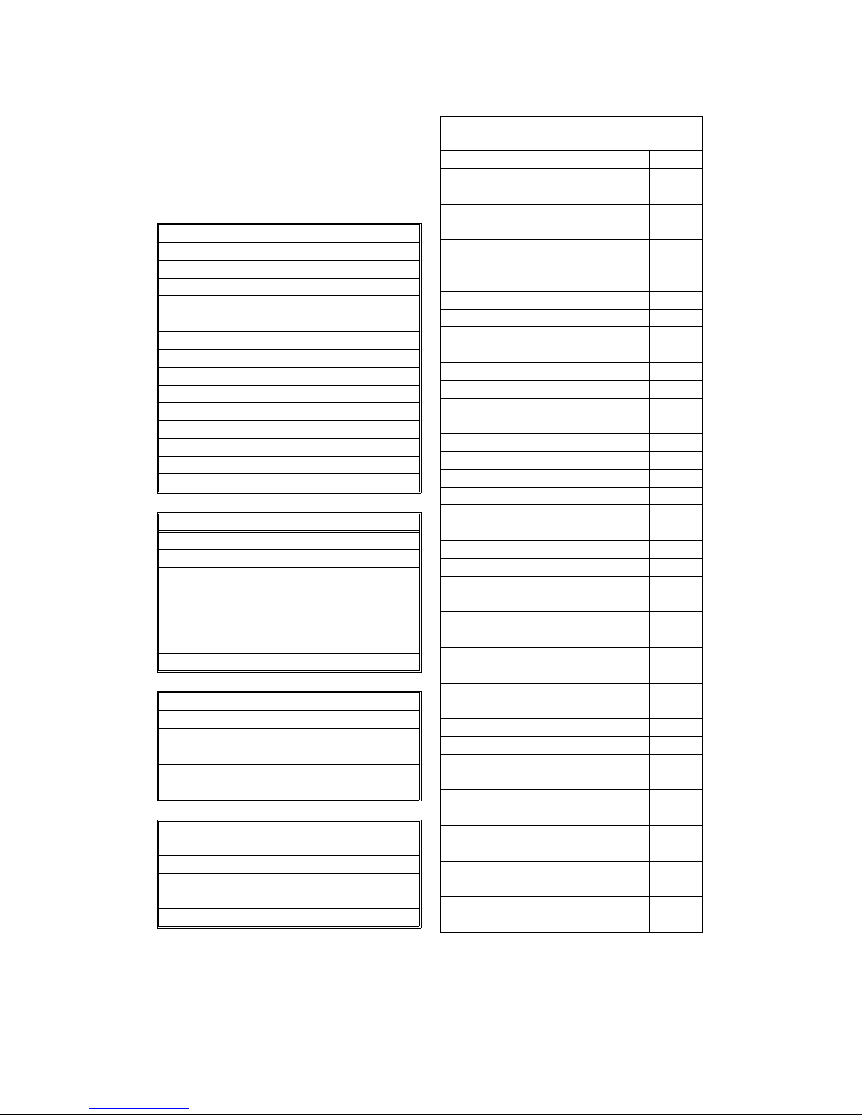
1.1. SPECIFICATIONS
Type
Desktop type transceiver
Circuit
PSTN, PABX
Connection
Direct couple
Document Size
Length:
105 - 355.6 mm [4.1 - 14 ins]
(automatic feed)
Up to 600 mm [23.6 ins] (manually assisted)
Width:
148 - 216 mm [5.8 - 8.5 ins]
Thickness:
0.05 to 0.2 mm [2 to 8 mils]
(equivalent to 50 - 90 g/m
2
)
Document Feed
Automatic feed, face up
ADF Capacity
30 sheets (using 20 lb. or 80 g/m
2
paper)
Scanning Method
Contact image sensor
Maximum Scan Width
204 mm [8.0 ins]
Scan Resolutions
Main scan: 8 dots/mm [203 dpi]
Sub scan:
Standard - 3.85 lines/mm [98 lpi]
Detail - 7.7 lines/mm [196 lpi]
Fine - 15.4 lines/mm [392 lpi]
Memory Capacity
ECM: 128 kbytes
SAF: 240 kbytes (18 pages/ITU-T #1 test
document), extra 1 Mbyte memory card
available (102 pages) or 2 Mbyte memory
card available (186 pages)
Compression
MH, MR, EFC, MMR, SSC
Protocol
Group 3 with ECM
Modulation
V.17 (TCM), V.29 (QAM), V.27ter (PHM),
V.21 (FM)
Data Rate (bps)
14400/12000/9600/7200/4800/2400
Automatic fallback
Transmission Time
6 s at 14,400 bps; Measured with G3 ECM
using memory for a ITU-T #1 test document
(Slerexe letter) at standard resolution
Printing System
Laser printing, plain paper, dry toner
Paper Size and Capacity
Standard Tray: 150 sheets
(using 20 lb. or 80 g/m
2
paper)
A4, Letter, Legal, F4
Paper Feed Unit (Optional): 250 sheets
(using 20 lb. or 80 g/m
2
paper)
A4, Letter, Legal
Maximum Printing Width
216 mm [8.5 ins]
Print Resolutions
Fax and Copy Mode:
Main scan: 16 dots per mm [406 dpi]
Sub scan: 15.4 lines/mm [391 lpi]
Power Supply
USA: (110 - 120 Vac) ± 10%, 60 ± 3 Hz
Europe/Asia: (220 - 240 Vac) ± 10%,
50/60 ± 3 Hz
Power Consumption (Base Machine Only)
USA: Maximum 390 W
Europe/Asia: Maximum 470 W
Operating Environment
Temperature: 15 - 25 °C [59 - 77 °F]
Humidity: 35 - 70 %Rh
Dimensions (W x D x H)
380 x 341 x 219 mm [15.0 x 13.4 x 8.6 ins]
Excluding handset, trays, and optional units
Weight
Approx. 7 kg [15 lb.]
Excluding consumables, handset, trays, and
optional units
July 24th, 1996 OVERALL MACHINE INFORMATION
SPECIFICATIONS
1-1
1.2. FEATURES
KEY: O = Used, X = Not Used,
A = With optional memory only,
B = With optional paper feed unit only
C = With optional handset only
Equipment
ADF O
Book scan X
Built-in handset X
Bypass feed: 1 sheet X
Optional paper feed unit B
Cabinet X
Mechanical Counter X
Cutter X
Handset C
Hard disk X
Manual feed mechanism X
Marker (Stamp) X
Monitor speaker O
Optional printer interface (RS422) X
Video Processing Features
Contrast O
Halftone (Basic & Error Diffusion) O
MTF O
Enlarge/Reduction: Three en-
largements, 4 reductions (50%200%)
X
Resolution O
Smoothing to 16 x 15.4 l/mm O
Communication Features - Aut o
Automatic fallback O
Automatic redialing O
Confidential reception X
Dual Access O
Substitute reception O
Communication Features -
User Selectable
Action as a transfer broadcaster X
AI Redial X
Answering machine interface O
Authorized Reception O
Communication Features -
User Selectable
Auto-answer delay time O
Auto dialing (pulse or DTMF) O
Auto Document X
Auto image density selection X
Auto paper size selection X
Automatic Voice Mess age X
Batch Transmission (max 35
files)
O
Broadcasting O
Chain Dialing O
Communication Result Display X
Confidential ID Override O
Confidential Transmission X
Direct Fax Number Entry O
Economy Transmission X
Fax on demand X
Forwarding X
Free Polling O
Groups (3 groups) O
Group Transfer Station X
Hold X
ID Transmission O
Immediate Redialing O
Immediate transmission O
Keystroke Programs X
Memory transmission O
Multi-step Transfer X
Next Transfer Station X
OMR X
On Hook Dial O
Ordering Toner X
Page Count O
Personal Codes X
Personal Codes with Conf. ID X
Polling Reception O
Polling Transmission X
Polling tx file lifetime in the SAF O
Quick Dial (10 stations) O
Reception modes (Fax, Tel, Auto) O
Length Reduction O
Remote control features X
Remote Transfer X
Restricted Access X
Secured Polling O
OVERALL MACHINE INFORMATION July 24th, 1996
FEATURES
1-2

Communication Features -
User Selectable
Secured Polling with Stored ID
Override
O
Secure Transmission X
Send Later O
Silent ringing detection X
Specified Image Area X
Speed Dial (50 stations) O
Super Fine Resolution
(16 x15.4 l/mm : 400 x 400 dpi)
X
Telephone Directory X
Tonal Signal Transmission O
Transfer Request X
Transmission Deadline (TRD) X
Turnaround Polling X
Two-step Transfer X
Two in one X
Voice Request X
Communication Features -
Service Selectable
AI Short Protocol O
Auto-reduction override option O
Busy tone detection O
Closed Network (tx and rx) X
Continuous Polling Reception X
Dedicated tx parameters O
ECM O
EFC O
Inch-mm conversion X
Page retransmission times O
Page separation mark O
Protection against wrong conn. O
Resol’n stepdown override option X
Short Preamble X
Well log X
Other User Features
Area code prefix X
Automatic service call Service
Center mark X
Checkered mark X
Clearing a memory file O
Clearing a polling file O
Clock O
Other User Features
Confidential ID X
Copy editing (Erase Center/Mar-
gin)
X
Copy mode O
Copy Mode Restriction X
Counters O
Daylight Saving Time O
Destination Check X
Direct entry of names O
File Retention Time X
File Retransmission X
Function Programs X
ID Code X
Label Insertion X
Language Selection O
LCD contrast control Service
Memory Lock X
Memory Lock ID X
Modifying a memory file X
Multi Sort Document Reception X
Multicopy mode O
Own telephone number O
Power Saver (Night Timer and
standby mode)
O
Print density control O
Printing a memory file O
RDS on/off O
Reception Mode Switching Timer X
Reception time printing X
Reduction/Enlargement X
Remaining memory indicator O
Remote ID X
Reverse Order Printing X
RTI, TTI, CSI O
Secure ID X
Service Report Transmission O
Speaker volume control O
Specified Cassette Selection X
Substitute reception on/off O
Telephone line type O
Toner Saving Mode O
TTI on/off O
User Function Keys X
User Parameters O
Wild Cards O
July 24th, 1996 OVERALL MACHINE INFORMATION
FEATURES
1-3
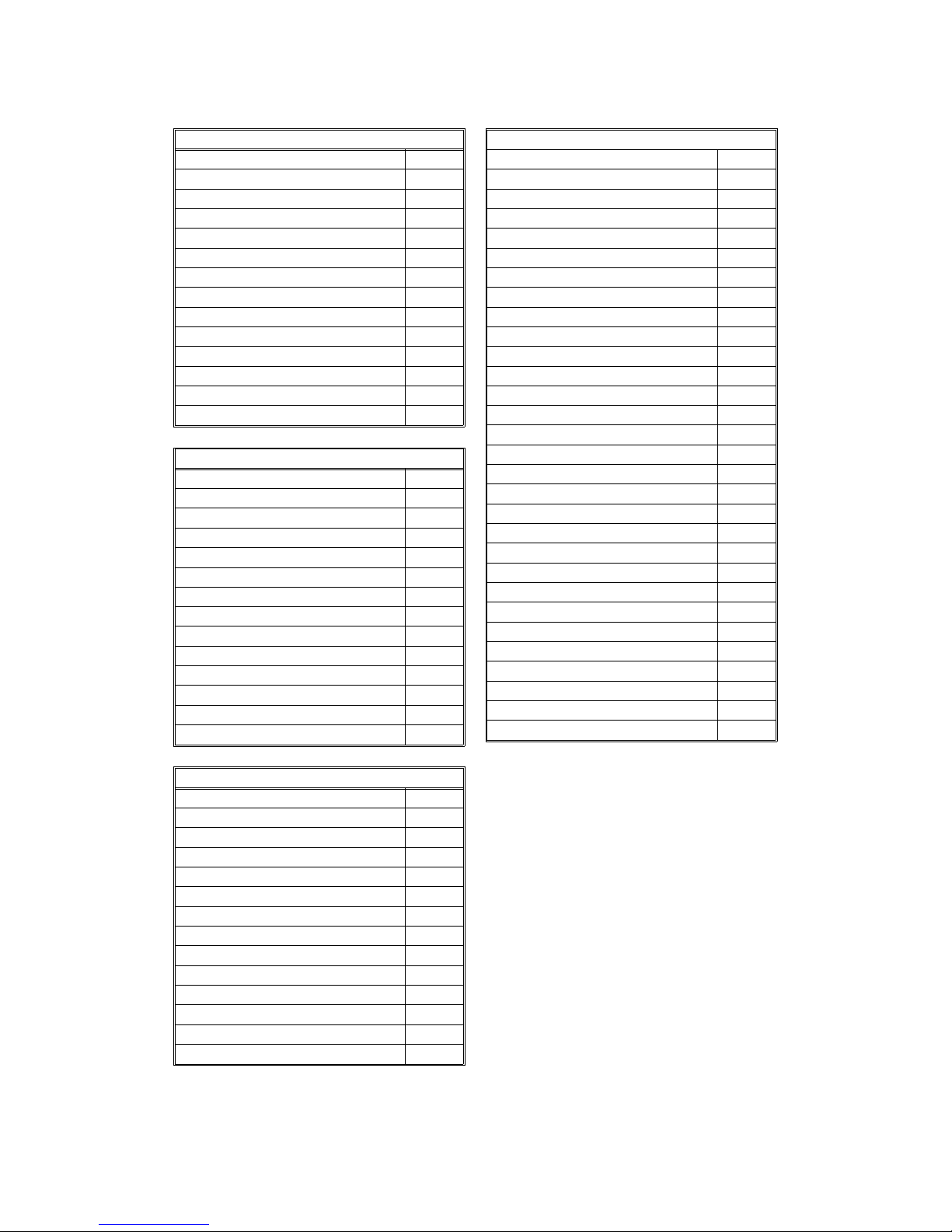
Reports - Automatic
Charge Control Report X
Communication Failure Report O
Confidential File Report X
Error Report O
Memory Storage Report O
Mode Change Report X
Polling Clear Report O
Polling Reserve Report O
Polling Result Report O
Power Failure Report O
TCR (Journal) O
Toner Cassette Order Form X
Transfer Result Report X
Transmission Result Report O
Reports - User-initiated
Authorized Reception List O
Charge Control Report X
File List O
Forwarding List X
Group List O
Personal Code List O
Program List X
Quick Dial List O
Specified Cassette Selection List X
Speed Dial List O
TCR O
Transmission Status Report X
User Function List X
User Parameter List O
Service Mode Features
Auto Paper Select test X
Back-to-back test X
Bit switch programming O
Book mode test X
Buzzer test O
Cable equalizer O
Comm. parameter display O
Counter check O
Country code O
DTMF tone test O
Echo countermeasure O
Effective term of service calls O
Error code display O
Excessive jam alarm O
Service Mode Features
File Transfer O
LCD contrast adjustment O
Line error mark O
Memory file printout (all files) O
Modem test O
NCU parameters O
Operation panel test O
Periodic service call O
PM Call O
Printer mechanism test O
Printer test patterns O
Programmable attenuation X
Protocol dump list O
RAM display/rewrite O
RAM dump O
RAM test O
Ringer test X
Scanner lamp test O
Scanner mechanism test O
Sensor initialization X
Serial number O
Service monitor report O
Service station number O
Software upload/download O
SRAM data download O
System parameter list O
Technical data on the TCR O
Thermal head parameters X
Transmission Status Report X
User data transfer O
Memory Files
Max. number of files: 100
Max. number of stations/file: 30
Max. number of stations overall: 100
OVERALL MACHINE INFORMATION July 24th, 1996
FEATURES
1-4
1
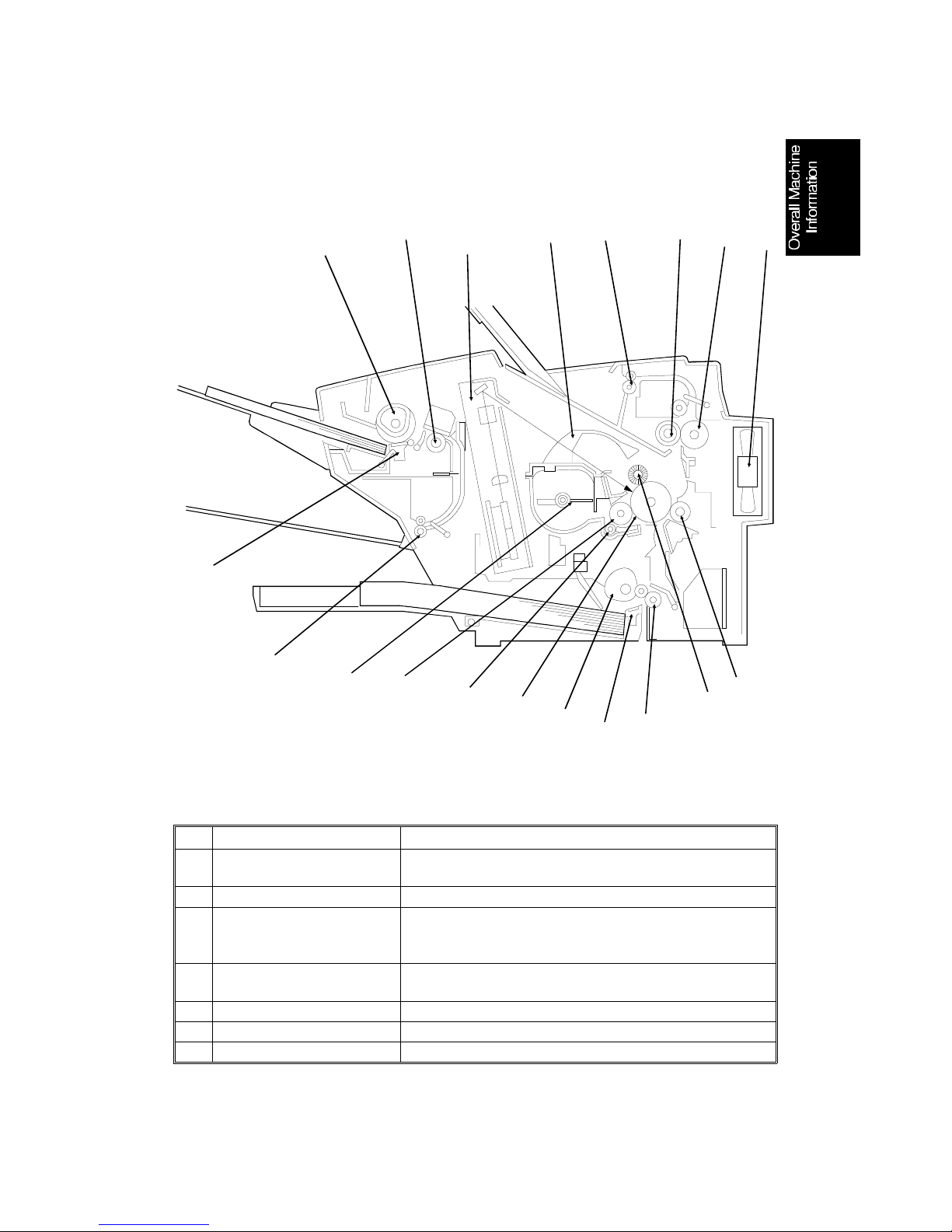
1.3. COMPONENT LAYOUT
1.3.1. Mechanical Components
No. Name Description
1
Document Pick-up Roller Picks up the top sheet of the document from the
document table.
2
Scanner Roller Feeds the document through the scanner.
3
Laser Unit Consists of the LDDR (Laser Diode Driver), focusing
lens, Fθ Lenses, square mirror motor, and other laser
optic components.
4
Development Toner
Magazine
Consists of the toner supply mechanisum, the toner
tank, and the development unit.
5
Paper Feed-out Roller Feeds paper out of the machine.
6
Hot Roller Heat from this roller fuses the toner to the copy paper.
7
Fusing Pressure Roller Applies pressure to the paper during the fusing process
2
3
4
10
5
7
8
19
18
17
16
13
14
12
11
9
6
15
H528V501.wmf
July 24th, 1996 OVERALL MACHINE INFORMATION
COMPONENT LAYOUT
1-5

No. Name Description
8
Fusing Fan Cools the interior of the machine.
9
Transfer Roller Applies a charge to the paper to pull the toner off the
drum and onto the paper.
10
Charge Brush Roller Applies a charge to the drum.
11
Paper Feed Roller Feeds paper from the paper tray into the printer.
12
Paper Separation Pad Allows one sheet into the printer.
13
Paper Pick-up Roller Picks up the top sheet of paper from the tray.
14
OPC Drum Organic Photoconductor Drum.
15
Toner Supply Roller Supplies the toner to the development roller.
16
Development Roller Applies toner to the latent image on the drum.
17
Toner Agitator Stirs up toner in the toner tank.
18
Document Feed-out
Roller
Feeds the document out of the scanner.
19
Document Separation Pad Allows one sheet into the scanner.
OVERALL MACHINE INFORMATION July 24th, 1996
COMPONENT LAYOUT
1-6
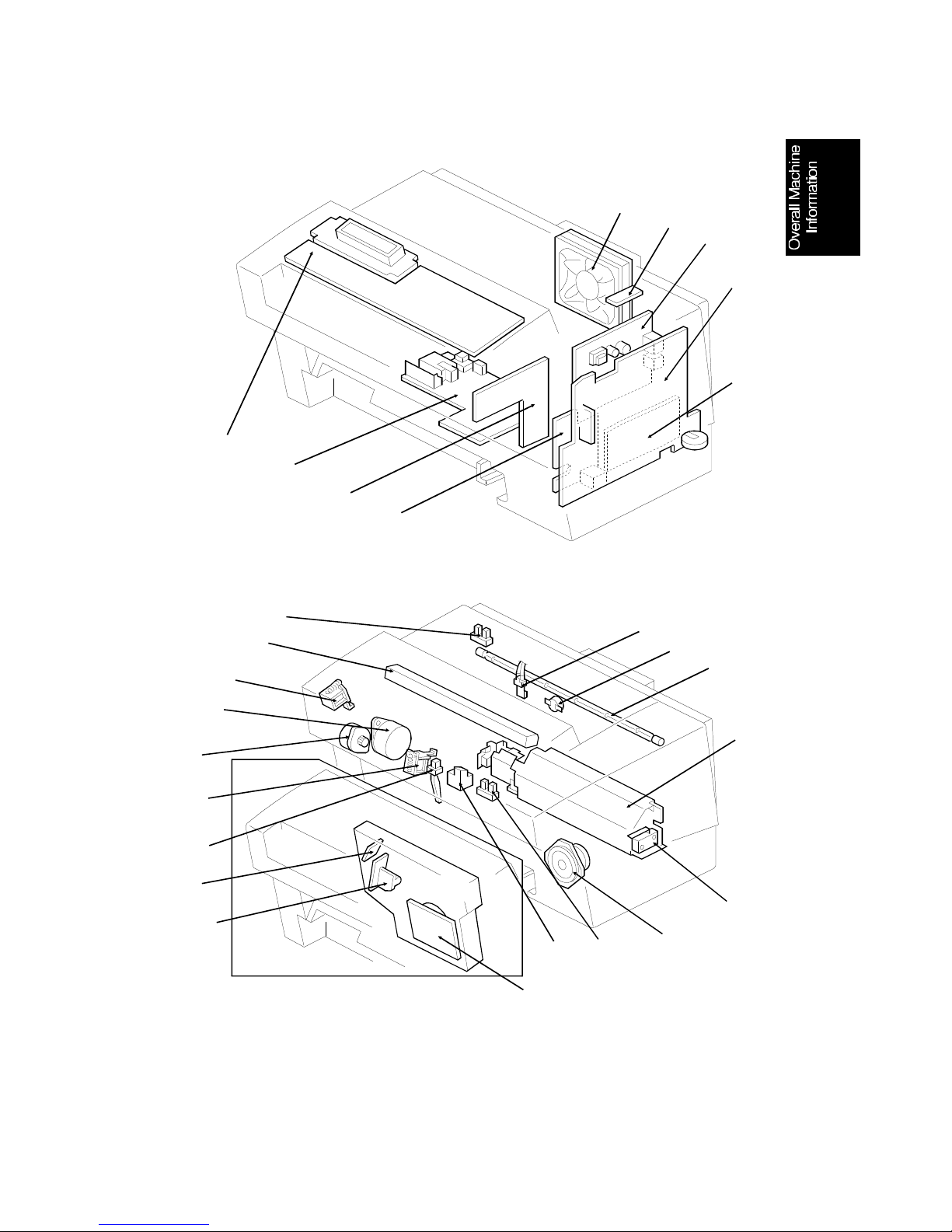
1.3.2. Electrical Components
6
7
8
9
5
4
3
2
1
H528V504.wmf
14
15
17
18
20
19
16
27
21
12
11
25
26
24
10
22
13
23
H528V503.wmf
July 24th, 1996 OVERALL MACHINE INFORMATION
COMPONENT LAYOUT
1-7

1. PCBs
No. Name Description
1
MCB (Mechacincal
Control Board)
Controls the printer part of the machine.
2
FCU (Facsimile Control
Unit)
Controls the machine.
3
NCU (Network Control
Unit)
Contains a relay and switches to interface the machine
to the network and the handset.
4
PCB-R Contains the resistors in the transfer bias circuit,
between the ground plate and ground.
6
OPU (Operation Panel
Unit)
Consists of the LCD and the key switches.
7
High-voltage Power
Supply
Supplies high voltages to the charge, transfer, and
development bias.
8
Scanner Sensor Board Contains the scanner sensors (document, scan line,
document exit), and the ADF cover open sensor .
9
5V Power Board Generates the +5VE supply.
21
LDDR (Laser Diode
Driver)
Drives the laser diode.
23
PSU (Power Supply Unit) Supplies power to the machine.
2. Motors
No. Name Description
20
Tx Motor Drives the scanner rollers.
18
Main Motor This DC stepper motor drives the printer mechanism.
22
Square Mirror Motor This high-speed servomotor drives the square mirror in
the laser unit.
5
Fusing Unit Fan Motor Cools the interior of the machine.
OVERALL MACHINE INFORMATION July 24th, 1996
COMPONENT LAYOUT
1-8

3. Sensors
No. Name Description
11
Thermostat Cuts off the ac power supply to the fusing lamp if the
surface temperature exceeds 180°C.
12
Thermistor Is used to monitor the hot roller surface temparature.
13
Toner End Sensor Is used to detect the toner end condition.
10
Registration Sensor Is used to detect when paper is fed into the printer.
14
Paper Exit Sensor Is used to detect when paper is at the fusing unit.
16
Paper End Sensor Is used to detect when the paper tray is empty.
27
Synchronization Detector Is used to synchronize the laser main scan.
4. Others
No. Name Description
15
Contact Image Sensor Reads and converts the light reflected from the
document into an analog video signal.
An LED array which illuminates the document is
included.
17
Document Pick-up
Solenoid
When this is energized, tx motor drive is transmitted to
the document pick-up roller.
19
Paper Pick-up Solenoid When this is energized, main motor drive is transmitted
to the paper pick-up roller.
25
Fusing Lamp The heat from this lamp fuses the toner to the paper.
24
Speaker Allows the user to listen to the condition of the machine
and the telephone line.
26
Interlock Switch If the top cover is open, this switch cuts off the
+24V(SW) power supply. This component is also used
as a top cover open sensor.
July 24th, 1996 OVERALL MACHINE INFORMATION
COMPONENT LAYOUT
1-9
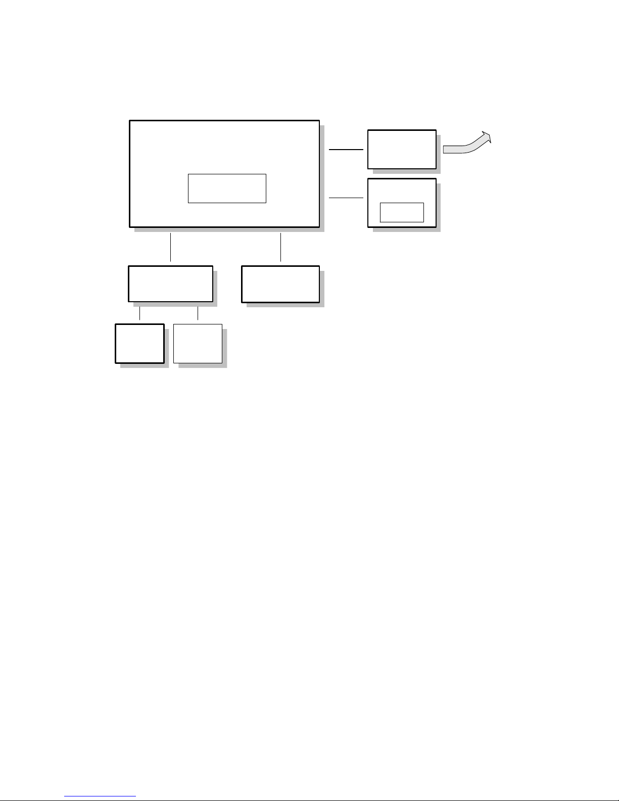
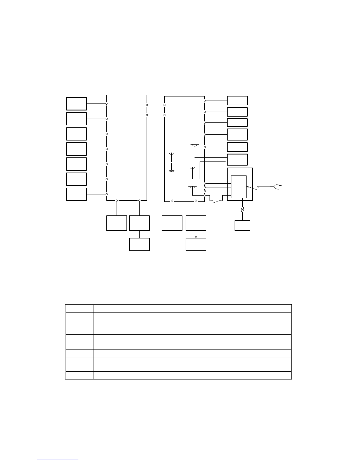
1.4. OVERALL MACHINE CONTROL
The FCU controls the entire system of the machin e.
The printer components and the opt ion al pa pe r fee d unit are cont rolle d by th e
MCB. The FCIP in the FCU is connected with the CPU in the MCB t hro ug h a
synchronized 8-bit serial interface. The line synchronization signal for laser
printing is sent to the FCIP from the MCB.
The scanner component s ar e con trolled by the FCU. Video data coming from
the CIS is processed in the FCI P and then sent to the MCB for copying or
sent to the NCU through the modem for transmission.
The operation panel is controlled by the FCU throu gh a serial int erface.
MCB
FCU
Operation
Panel
Printer
Components
Optional
Paper Feed
Unit
NCU
FCIP
Serial
Scanner
Components
Data &
Control
Data &
Control
AVIDEO
/STS
/SOD
To the Network
OP-LSI
TRXD
H528D501.wmf
OVERALL MACHINE INFORMATION July 24th, 1996
OVERALL MACHINE CONTROL
1-10
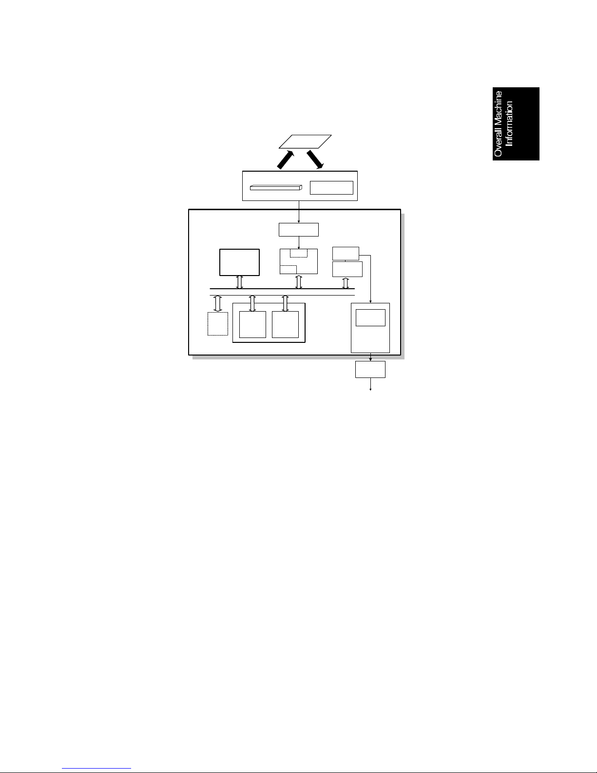
1.5. VIDEO DATA PATH
1.5.1. Transmission
Immediate Transmission:
Scanned data from the contact imag e sen sor passes to the DIP block in the
FCIP. After analog/digital vide o p roce ssing , the DCR block compresses the
data for transmission. The co mpre ssed data then passes eit he r to the FIFO
memory or to the ECM memory before it is sent to the telephone line through
the modem.
Memory Transmission:
First, the scanned data is stored in the SAF memory after compression in the
DCR block.
At the time for transmission, the DCR block decompre sses the data from the
SAF memory, then compresses it again after handshakin g with the other terminal is done. The compressed data the n passes eit he r to th e FIFO memory
or to the ECM memory, before it is sent to the telephone line throug h the modem.
FCU
DRAM
Video
Processing
Memory
Line
Buffer
/FIFO
Memory
ECM/SAF
Memory
CIS Video
Amplifier
DATA/ADDRESS BUS
To the
network
Original
Image Sensor
LED Array
Contact Image Sensor
Assembly
SAF IC
Card
R144EFXL
Modem
Amp
NCU
FCIP
DIP
DCR
Attenuator
HIC
DIP:Digital Image Processor
DCR:Data Compression &
Reconstruction
H528v507.wmf
July 24th, 1996 OVERALL MACHINE INFORMATION
VIDEO DATA PATH
1-11
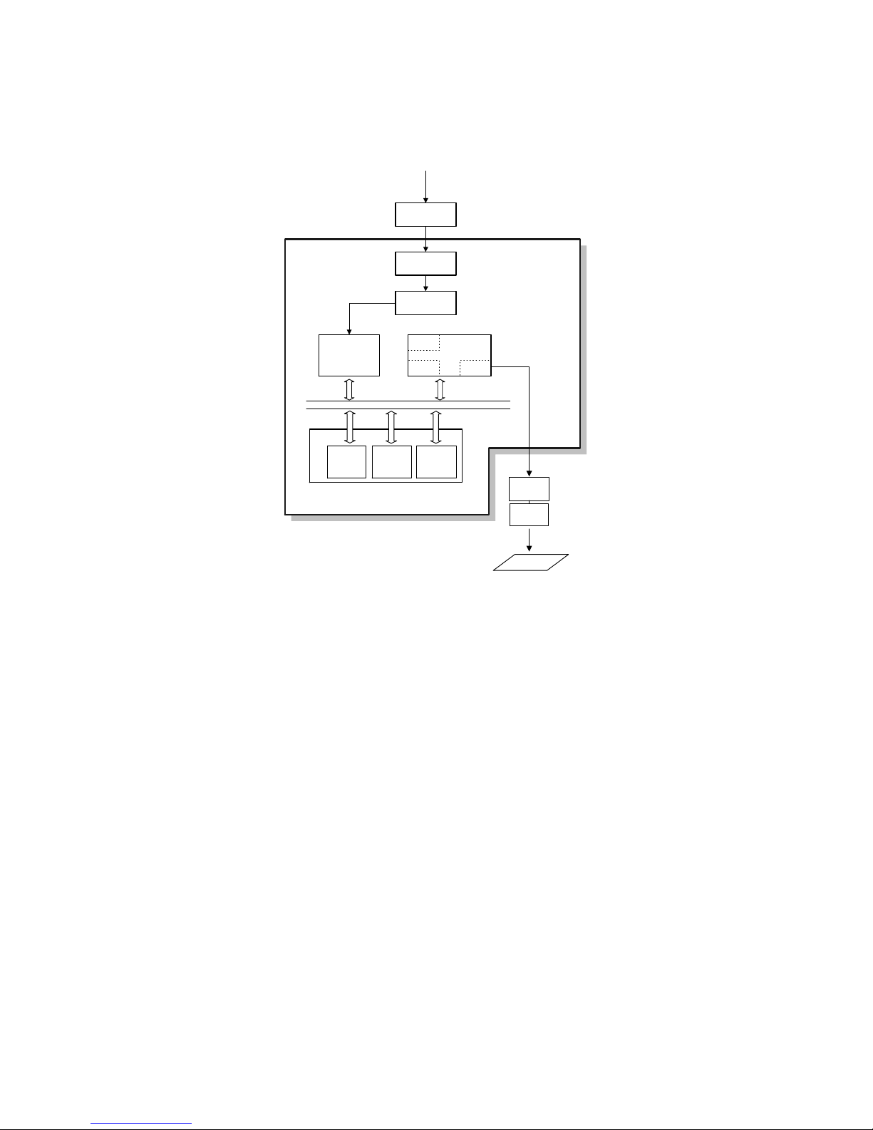
1.5.2. Reception
Data from the line passes to the modem through the NCU and hyb rid I C. A fter the modem demodulates the dat a, the data pa sses to the DCR block,
through either the FIFO or the ECM memory, where the data is decompressed to raster image data.
The raster image data is then p asse d t o t he pa ge memo ry fo r printing. After a
page of data has been stored in the pag e memo ry, the data is sent to the
MCB through the LIF block in the FCIP, and then to the LDDR.
Copy Paper
DATA/ADDRESS BUS
E144EFXL
Modem
Amplifier
FCIP
MDM
DCR LIF
HIC
NCU
From the Network
Line Buffer
/FIFO
Memory
ECM/SAF
Memory
Page
Memory
DRAM
MCB
LDDR
FCU
LIF: Laser Interface
DCR:Data Compression &
Reconstruction
MDM: Modem
H528v508.wmf
OVERALL MACHINE INFORMATION July 24th, 1996
VIDEO DATA PATH
1-12
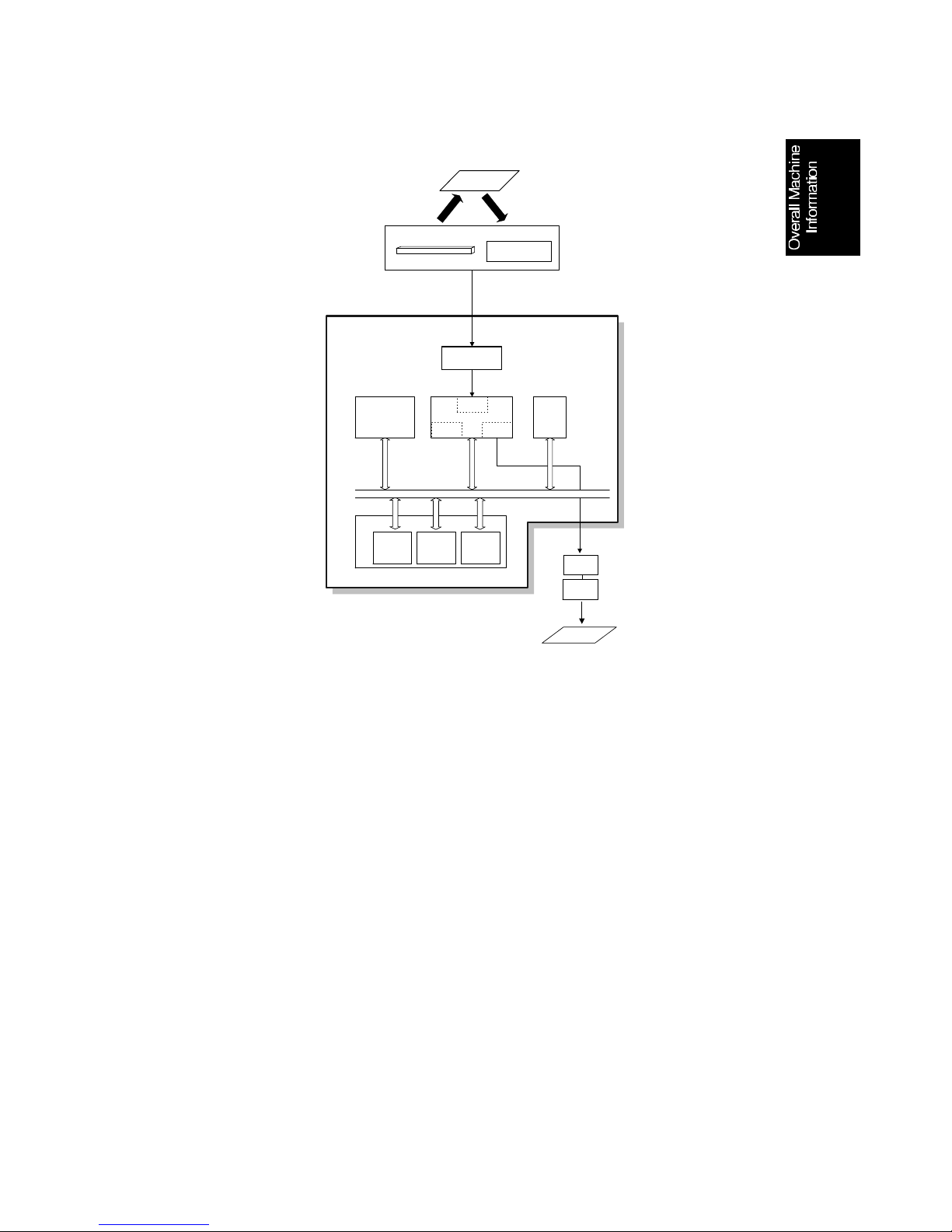
1.5.3. Copying
Single copy / Multi-page copy
The scanned data passe s to th e pa ge memory af ter video processing in the
DIP block in the FCIP. After a page of data has been stored in the page memory, the data is sent to the MCB through the LIF block, and then to the LDDR.
This process is the same for multi-page copyin g.
Original
Image Sensor
LED Array
Contact Image Sensor
Assembly
FCU
CIS Video
Amplifer
Copy Paper
Video
Processing
Memory
FCIP
DCR LIF
DIP
Line Buffer
/FIFO
Memory
ECM/SAF
Memory
Page
Memory
DRAM
MCB
LDDR
SAF
Memory
IC Card
DATA/ADDRESS BUS
LIF: Laser Interface
DCR:Data Compression &
Reconstruction
DIP:Digital Image Processor
H528v509.wmf
July 24th, 1996 OVERALL MACHINE INFORMATION
VIDEO DATA PATH
1-13
1.6. POWER DISTRI BUTI O N
1.6.1. Distribution Diagram
The PSU supplies +24V, +24V(SW), +12V, and ±5V dc power to the FCU.
The +5V Power Board generates +5VE from the +24V suply. The dc supplies
are used as follows.
+24V
This is normally on when the main switch is on.
+5VE
This is used for the document sensor, operation panel, and NCU. This is
supplied even if the machine is in power saver mode.
+12V
This supplies the LED Array in the CIS.
-5V
This is used for the image sensor.
+5V
This is normally on when the main switch on.
+12VP
This is supplied the to Flash ROM and the optional IC card.
+5VD
This supplies back up power for the system RAM and the optional IC card. A
lithium battery is used to generate +5VD.
+24V(SW)
This is interrupted if the interlock switch opens.
MCB
FCU
LDDR
Square
Mirror Motor
Toner End
Sensor
Fusing Fan
Paper
Pick-up
Solenoid
Thermistor
High
Voltage
Paper Supply
Optional
Paper
Feed Unit
Paper
Pick-up
Solenoid
+24V
(SW)
Document
Pick-up
Solenoid
5V
Power Board
PSU
Scanner
Sensor
Board
CIS
Sensor
LED Array
+12V
Fusing
Lamp
Thermostat
Main Switch
AC Main Power
+24V
+24V
Tx Motor
+5V
+5V
+24V(SW)
+5V
+24V(SW)
+24V(SW)
+5V
Main Motor
+24V(SW)
+24V(SW)
+24V(SW)
+5V
+5VE
+5V
+5V
-5V
+12V
NCU
Option
Panel
IC Card
+5V
-5V
+12V
+24V(SW)
+24V(SW)
+24V
+5VE
+5VE
+5V
+5V
+5VD
+12VD
+24V(SW)
Interlock
Switch
+5V
+24V(SW)
Power
Board
+5VD
+
-
+5VE
+24V
H528v510.wmf
OVERALL MACHINE INFORMATION July 24th, 1996
POWER DISTRIBUTION
1-14
2. DETAILED SECTION DESCRIPTIONS
2.1. SCANNER
2.1.1. Mechanisms
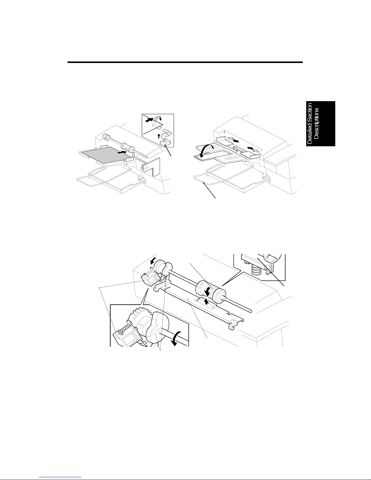
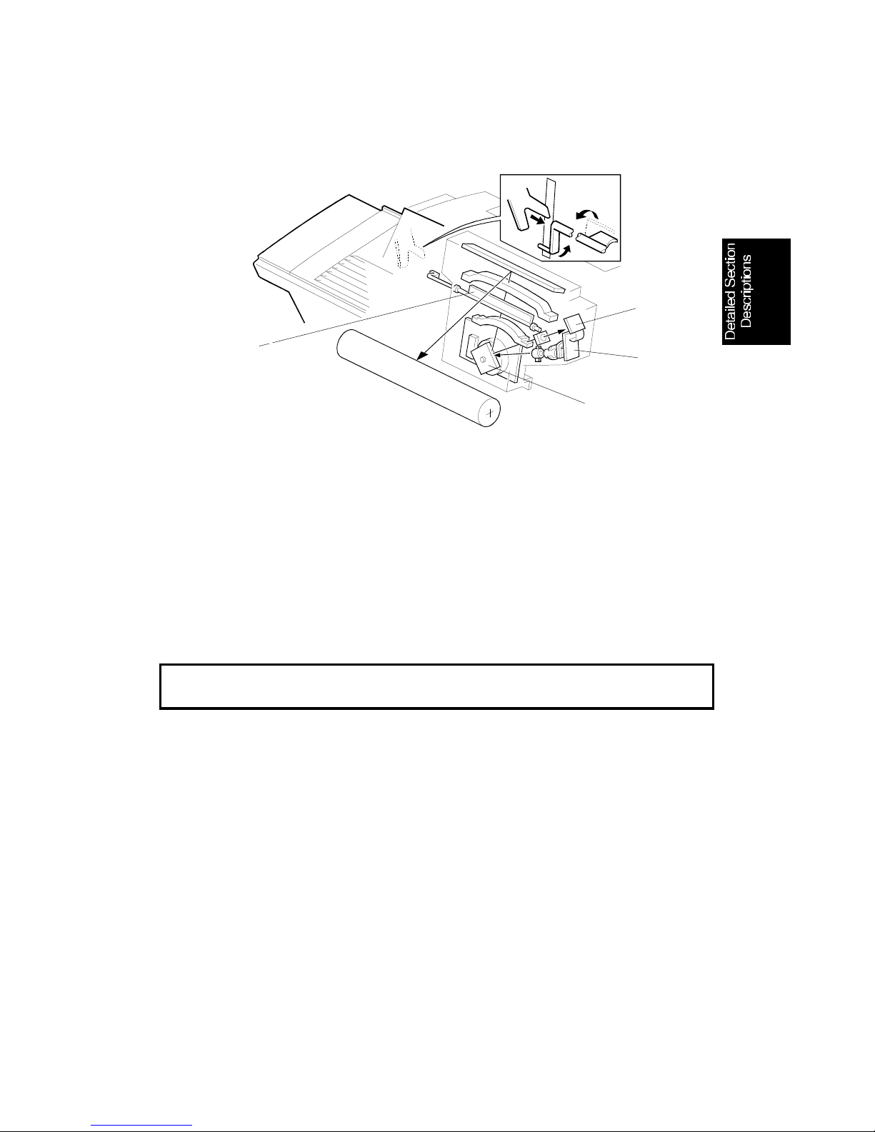
1. Document Detection
The document sensor [A] detects when a document is placed in the ADF. The
fold-out extension [B] helps support longer documents.
2. Pick-up and Separation
When the document pick-up soleno id [A ] is t urn ed on, it allows th e tray lifting
cam [B] to rotate. This allows the document plate [C] to be pushed up by a
spring under the plate. The docu ment pick-up roller [D] feeds the top sheet of
the document into the scanner. The sepa ration pad [E] prevents the document pick-up roller from feeding more than one sheet at the time.
[C]
[B]
H528D510.wmf
[A]
H528D511.wm f
[A]
[B]
[D]
[E]
H528D509.wmf
July 30th, 1996 DETAILED SECTION DESCRIPTIONS
SCANNER
2-1
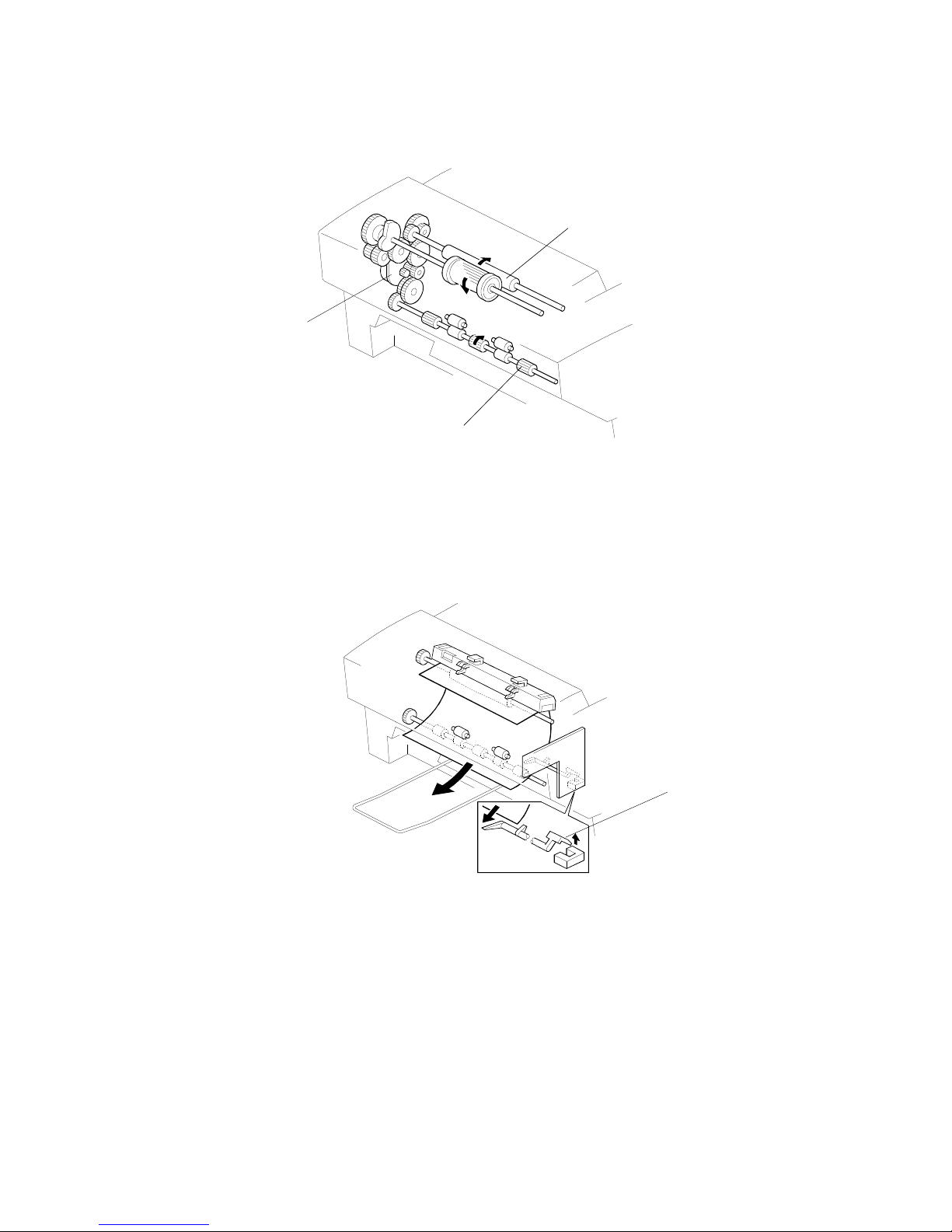
3. Drive Mechanism
The document is fed into the scanner by the scanner roller [A], and fed out by
the exit roller [B]. The tx motor [C] drives the scanner rolle r and th e exit ro ller.
The document exit sensor de te cts when the document leaves the scanner.
Note: When a communication error occu rrs in immediate tx, the machine
stops scanning the document, then feeds it out of the scanner.
[A]
[C]
[B]
H528D512.wmf
[D]
H528D513.wmf
DETAILED SECTION DESCRIPTIONS July 30th, 1996
SCANNER
2-2

4. Image Scanning
The scanner consists of a conta ct imag e sen sor (CIS) assembly [A] and a
scanner roller [B]. Inside the CIS are an exp osu re glass [C], a rod lens array
[D], an image sensor [E], and an LED array [F] .
The image sensor consists of a row of 1728 photo sen sitive eleme nt s (216
mm width x 8 dots/mm). Light from the LED array is reflected from the document and focused ont o th e image sensor by the rod lens array. Because of
the short optical p ath inside the CIS, the focal depth is much shorter than for
a CCD type scanner.
The white level adjustme nt is performed at the factory, then the white level is
stored in the FCU’s SRAM. The white level must be adjusted when the FCU
or the CIS is replaced, or the SRA M is clea red in the field .
The CIS scans the document one line at a time, and out pu ts an analog signal
for each line. The voltage from each ele ment depends on the intensity of the
light reflected by th e do cume nt onto the elemen t; the intensity of the light depends on the darkness of the area reflected.
Cross reference
White level adjustment: Service Tables and Procedures (chapter 4) - Function 10,
Shading Test
[A]
[B]
[C]
[D]
[E]
[F]
H528D515.wmf
July 30th, 1996 DETAILED SECTION DESCRIPTIONS
SCANNER
2-3

Standard resolution (Scanning to memory)
• 3.85 line/mm resolution.
• One line is read each motor step.
• Scan speed: 2.75 s /A4 size.
• The tx motor rotates at 800 pps to scan the document in to the memory.
• OR processing is always disabled to make scanning faster.
Standard resolution (Immedia te tx)
• 3.85 line/mm resolution.
• One line is read every two motor steps.
• Scan speed: 5.5 s /A 4 size.
• The tx motor rotates at 400 pps to scan the do cument.
• OR processing is done, to prevent narro w ve rtica l lines from being bro-
ken up (OR processing can be disabled with scann er switch 00, bit 4).
Detail resolution
• 7.7 line/mm resolution.
• One line is read every motor step.
• Scan speed: 5.5 s /A 4 size.
• The tx motor rotates at 400 pps to scan the do cument.
• In copy and halftone mo de , scan ning always uses detail resolution.
Fine resolution
• 15.4 line/mm resolution.
• One line is read every motor step.
• Scan speed: 11.0 s /A4 size.
• The tx motor rotates at 400 pps to scan the do cument.
DETAILED SECTION DESCRIPTIONS July 30th, 1996
SCANNER
2-4
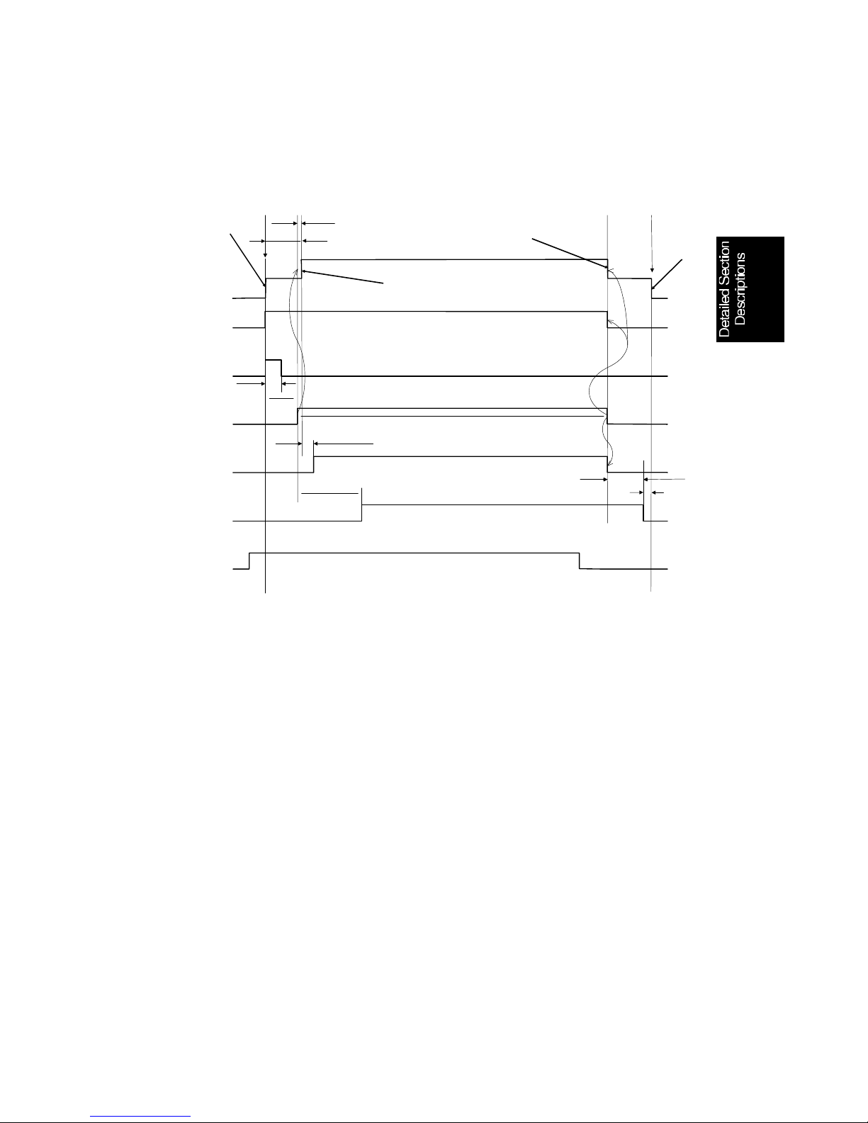
2.1.2. Scanner Timing Char t
1. Timing Chart
The following describes what is happening for the standard resolution at
points 1 to 4 on the timing chart.
1. When the St art key is pressed, the pick-up solenoid turn on, then the tx
motor feeds the documen t to the scan line sensor (400 pps).
2. The tx motor feeds the document through the scanner (800 pps).
3. The tx motor feeds the document out of the scanner.
4. The tx motor stops 82 steps after th e do cument exit sensor was turned off.
TX Motor
Document
Sensor
CIS LED
Document
Pick-up
Solenoid
Scan Line
Sensor
Data
Read
Document
Exit
Sensor
800PP
S
400PP
S
ON
OFF
ON
OFF
ON
OFF
ON
OFF
ON
OFF
ON
OFF
500ms
187 Steps
START
EXIT
Pre-feeding 2.05 S
38 Steps
37 Steps
[L2]
[L1]
[T1]
[L3]
1
2
3
4
H528d543.wmf
July 30th, 1996 DETAILED SECTION DESCRIPTIONS
SCANNER
2-5

2. Jam Conditions
The main cpu detects a docume nt ja m if one of th e fo llowing conditions occurs.
Jam Condition Description Error
Code
Non-feed
The scan line sensor does not switch on within
3.9 s [T1] of the tx motor starting.
The jam condition is reset when the document,
scan line, and exit sensors are turned off.
1-00
Maximum document
length exceeded
The scan line sensor does not turn off after the
maximum document length [L1] has been fed
since it turned on.
The jam condition is reset when the document,
scan line, and exit sensors are turned off.
1-01
The document exit sensor does not turn off after
the maximum document length [L3] has been fed
since the scan line sensor turned off.
The jam condition is reset when the document,
scan line, and exit sensors are turned off.
1-17
Document jam
The document exit sensor does not turn on when
the tx motor has rotated for 160 mm feed length
[L2] after the scan line sensor turned on.
The jam condition is reset when the document,
scan line, and exit sensors are turned off, and the
ADF cover opened then closed.
No error
code
When the document exit sensor is off while the
scan line sensor goes to off.
The jam condition is reset when the document,
scan line, and exit sensors are turned off, and the
ADF cover opened then closed.
Cover open
The top cover is opened while the machine is
working.
The jam condition is reset when the top cover and
the ADF cover are closed.
No error
code
Others
The scan line, document, or document exit sensor
is on during initialization.
The jam condition is reset when the document,
scan line, and exit sensors are turned off.
No error
code
DETAILED SECTION DESCRIPTIONS July 30th, 1996
SCANNER
2-6
2.2. PRINTING
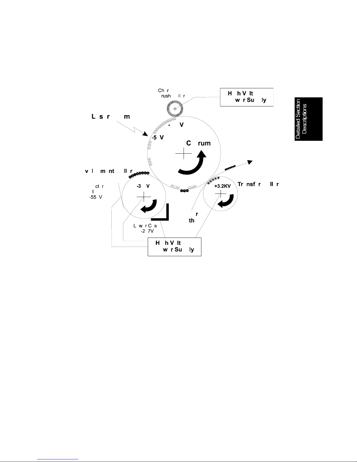
2.2.1. Printing Process - Overview
This machine uses a "write to black" syste m, usin g ne gative toner.
• The charge brush roller applies a negative charge to th e dru m o f -35 0 V
to -1350 V, switched at 30 Hz.
• The surface voltage of the drum is appro ximat ely -800 V.
• The laser expo sed a rea o n the dru m drop s to abou t -50 V.
• The development roller carries toner to the latent ima ge on the drum
surface. The bias voltag es during printing:
Development roller : -300 V
Doctor blade: -550V
Lower case: -287 V
• The transfer roller attract s ton er from the drum onto the paper. The bias
applied is +3.2 kV.
• This machine has no cleaning un it or waste toner tank.
H528D545.wmf
DETAILED SECTION DESCRIPTIONS June 30th, 1996
PRINTING
2-7

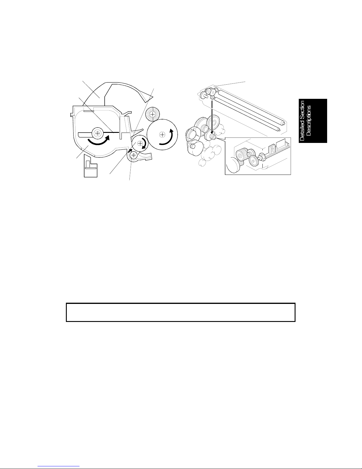
2.2.2. OPC Drum
This machine uses an organic photo conductor drum [A]. The diameter of the
drum is 30 mm. It is driven by the main motor [B] through a gear train [ C]. The
charge brush roller [D] is also driven by the main motor.
The drum cartridge is replace ab le by th e user.
2.2.3. Charge
The charge brush roller [A] is loca ted in th e dru m u nit. It app lies th e
char ge b ia s in di r e ct co n ta c t w i th t he d ru m [ B ]. The high voltage power
supply applies a high voltage of -350 V to -1350 V, switched at 30 Hz,
through plate [C].
Since the machine uses a charge brush roller, the ozone prod uction is greatly
reduced and the charge bias applied to a roller is relatively lo w compa red to
that for a corona wire.
The charge brush roller rot at es fa ster than the drum. (The speed ratio is
about 4 : 1.)
There is no cleaning me cha nism. Also, toner is transferred back to the drum
by the transfer roller in cleaning mode. The charge brush roller picks up some
of this toner. In extreme cases, this may lead to vertical black lines on copies
in areas corresponding to places on the brush that have excessive toner.
[D]
[A]
[C]
[B]
H528D506.wmf
[A]
[B]
[C]
H528D517.wmf
July 30th, 1996 DETAILED SECTION DESCRIPTIONS
PRINTING
2-8
2.2.4. Laser Exposure
1. Overview
The components of the laser section create a latent image on the drum. The
charge on the exposed areas of the drum drops to about -50 V while
non-exposed areas rema in at abo ut -8 00 V.
This machine uses a rotatin g squ are mirror [A]. The beam emitted from the
LDDR [B] is reflected by the square mirror to the lin e synch ron ization detector
[C] for line synchronization in the main scan directio n. The mirror’s rotation
speed is 8431.7 rpm.
As a safety feature, the shutter [D] closes to block the laser beam path
whenever the top cover is opened.
Cross reference
Group 3 Facsimile Manual: section 4-3-3
2. Error Conditions
LD Failure:
The mechanical control board de te cts an LD failu re whe n the laser power is
out of the specified ran ge . Whe n this occurs, the machine warns the user on
the LCD panel (SC code 2-22).
[C]
[B]
[A]
[D]
H528D505.wmf
DETAILED SECTION DESCRIPTIONS June 30th, 1996
PRINTING
2-9

Mirror Motor Failure:
The machine detects a mirro r motor error when the MCB does no t de te ct the
line synchronization detector signal within 1 second of the mirror motor being
turned on. The machine also dete cts a mirror mot or e rror when the motor
rotation is not within 8431.7 rpm ± 5% at 4.2 seconds after the motor turns on
or if the motor is not within 8431.7 rpm ± 3% for more than 0.5 second during
mirror motor operation. Since this error is det ect ed wit h the line
synchronization dete ctor signal, the machine may detect LD malfunction as a
mirror motor failure. When these errors occur, the machine warns the user on
the LCD panel (SC code 3-31).
Cross reference
Service Call Conditions: section 7-3
3. T one r Savi ng Mode
In this machine, toner savin g is d on e by red ucin g the number of dots actually
printed, not by varying the de velopment bias. In toner saving mode, the
image data is filtered through the following four-line mat rix.
1st line 1 0 1 0 1 0 1 0 1 0 . . . . .
2nd line 0 0 0 0 0 0 0 0 0 0 . . . . .
3rd line 0 1 0 1 0 1 0 1 0 1 . . . . .
4th line 0 0 0 0 0 0 0 0 0 0 . . . . .
(1: Actual data printed, black or white; 0: Always a whit e pixel)
Note: • Toner saving mode only works when printing fax messages and re-
ports. (However, toner saving is disabled when receiving a halftone mode message in NSF/NSS mode.)
• When toner saving mode is selected, the print image density is
automatically set to "Normal"; in some cases, the image may be come invisible if the Lighter settin g is used .
Cross Reference
Toner Saving Mode: User parameter 12, bit 2
Edge Enhancement
In toner saving mode, the mach ine print s a black pixe l when eve r t he dat a
changes from white to black in the main scan direction. In this way, edges on
the image are printed more clearly.
July 30th, 1996 DETAILED SECTION DESCRIPTIONS
PRINTING
2-10
2.2.5. Development
1. Overview
This machine contains a develo pme nt ton er mag azin e (DTM) [ A] , which
contains the toner agita to r [B] , de velo pme nt roller [C], toner supply roller [D],
doctor blade [E], and the toner tank [F].
At toner end, the entire DTM is replaced by the user.
There are two rollers in the DTM: the toner application roller [D] and the
development roller [C].
The toner agitator [B] stirs the tone r and carries it to the ton er sup ply roller
[D]. The toner is then carried from the toner supply roller to th e develop ment
roller. As the development roller turns past the doctor blade [E], only a thin
coating of negatively charged tone r particles stay adhered.
Cross reference
Group 3 Facsimile Manual: section 4-4-2
During printing, a bias volta ge of -280 V is app lied to th e de velo pme nt roller
(when a print density setting of No rmal is sele cted). The development bias
changes in accordance with the print den sity sele ction (user parameter 12,
Bit 3 and 4).
Since the laser exposed are as on the drum are re duced to -50 V, the toner is
trasnferred from the de velopment roller onto these areas of the latent ima ge
as they turn past the drum.
There is no DTM detection in this machin e.
[B]
[C]
[D]
[E]
[A]
[F]
H528D508.wmf
[A]
H528D507.wmf
DETAILED SECTION DESCRIPTIONS June 30th, 1996
PRINTING
2-11
2. Development Bias
The high voltage power supply [A] applies differe nt volta ge s to th e
components of the DTM. The applied voltages are:
• Development roller: -280 V [B] (dep ending on the user’s print density
selection)
• Doctor blade: -550 V [C]
• Lower casing: -287 V [D]
The toner is negatively charged by the friction generated by the toner agita to r.
[A]
[B]
[C]
[D]
H528D516.wmf
July 30th, 1996 DETAILED SECTION DESCRIPTIONS
PRINTING
2-12
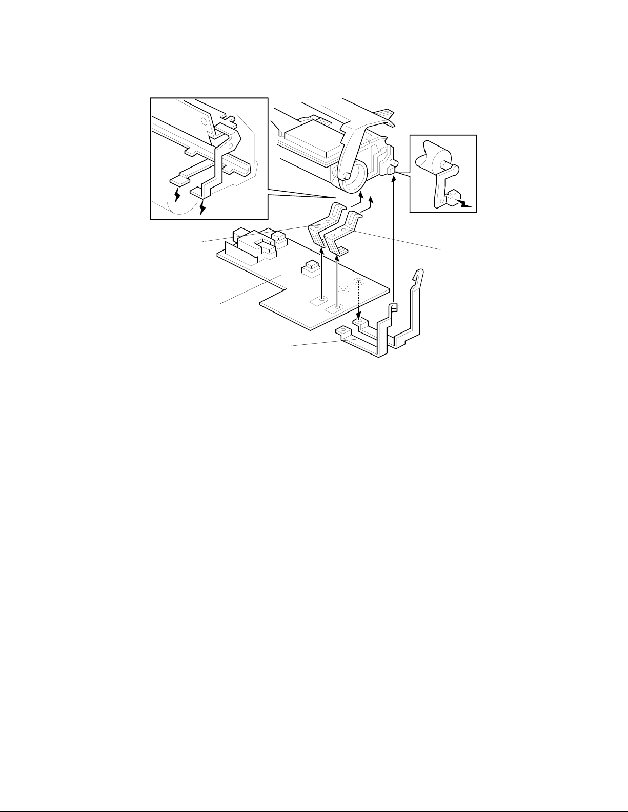
3. Toner End Detection
The toner end sensor [A] (a
reflective photosensor) is located
under the DTM. When the toner is
almost empty, the sensor’s light is
reflected by the mirror [B] at the top
of the toner tank. Th e machine
monitors this sensor only whe n the
main motor is on. If the sensor
detects the reflected ligh t 5 time s in
a row, within a specified period, the
MCB detects a toner near end
condition, and informs the FCU. The
machine can then print 100 more
sheets, at which time the FCU
disables printing (toner end
condition). At this time the DTM
must be replaced.
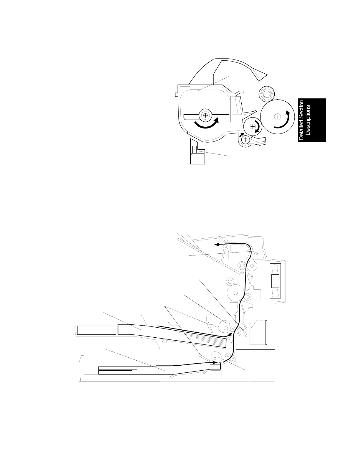
2.2.6. Paper Feed
1. Paper Path
[A]
[B]
H528D508.wmf
[A]: Paper Pick-up Roller
[B]: Paper Feed Unit Pick-up Roller
[C]: Registration Sensor
[D]: Paper Exit Sensor
[E]: Paper End Sensor
[F]: Standard Tray
[G]: Optional Paper Feed Unit
[A]
[B]
[C]
[D]
[F]
[G]
[E]
H528D547.wmf
DETAILED SECTION DESCRIPTIONS June 30th, 1996
PRINTING
2-13
 Loading...