

Page 1

Model G-P3
Machine Code: G190
SERVICE MANUAL
January, 2008
Subject to change
Page 2

Safety Notices
Important Safety Notices
Prevention of Physical Injury
1. Before disassembling or assembling parts of the printer and peripherals, make sure that the printer
power cord is unplugged.
2. The wall outlet should be near the printer and easily accessible.
3. If any adjustment or operation check has to be made with exterior covers off or open while the main
switch is turned on, keep hands away from electrified or mechanically driven components.
4. The printer drives some of its components when it completes the warm-up period. Be careful to keep
hands away from the mechanical and electrical components as the printer starts operation.
5. The inside and the metal parts of the fusing unit become extremely hot while the printer is operating.
Be careful to avoid touching those components with your bare hands.
Health Safety Conditions
Toner and developer are non-toxic, but if you get either of them in your eyes by accident, it may cause
temporary eye discomfort. Immediately wash eyes with plenty of water. If unsuccessful, get medical
attention.
Observance of Electrical Safety Standards
The printer and its peripherals must be serviced by a customer service representative who has completed
the training course on those models.
Lithium Batteries
Incorrect replacement of lithium battery(s) on the EGB and controller board may pose risk of explosion.
Replace only with the same type or with an equivalent type recommended by the manufacturer. Discard
used batteries in accordance with the manufacturer’s instructions.
Safety and Ecological Notes for Disposal
1. Do not incinerate toner bottles or used toner. Toner dust may ignite suddenly when exposed to an
open flame.
1
Page 3
2. Dispose of used toner, the maintenance unit which includes developer or the organic photoconductor
in accordance with local regulations. (These are non-toxic supplies.)
3. Dispose of replaced parts in accordance with local regulations.
4. When keeping used lithium batteries in order to dispose of them later, do not put more than 100
batteries per sealed box. Storing larger numbers or not sealing them apart may lead to chemical
reactions and heat build-up.
LASER SAFETY
The Center for Devices and Radiological Health (CDRH) prohibits the repair of laser-based optical units
in the field. The optical housing unit can only be repaired in a factory or at a location with the requisite
equipment. The laser subsystem is replaceable in the field by a qualified Customer Engineer. The laser
chassis is not repairable in the field. Customer engineers are therefore directed to return all chassis and
laser subsystems to the factory or service depot when replacement of the optical subsystem is required.
• Use of controls, or adjustment, or performance of procedures other than those specified in this
manual may result in hazardous radiation exposure.
• Turn off the main switch before attempting any of the procedures in the Laser Optics Housing Unit
section. Laser beams can seriously damage your eyes.
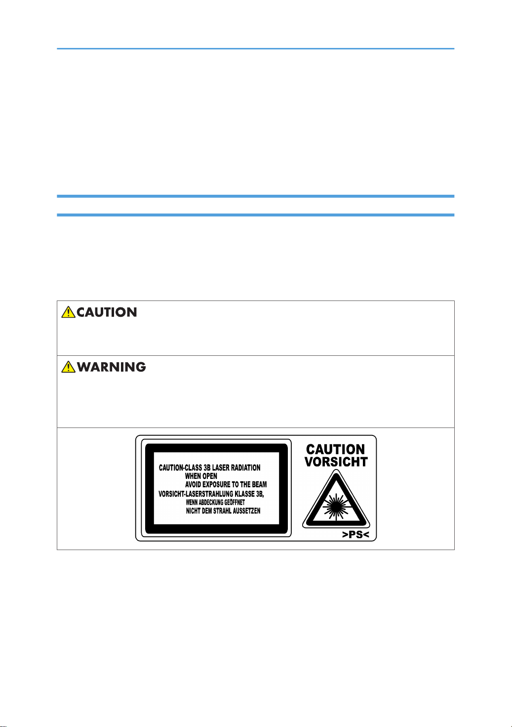
• CAUTION MARKING:
2
Page 4

Symbols, Abbreviations, and Trademarks
Symbols and Abbreviations
This manual uses the symbols and abbreviations shown below.
Symbol Meaning
* Refer to section number
Clip ring
Screw
Connector
Clamp
E-ling
SEF Short Edge Feed
LEF Long Edge Feed
Trademarks
Microsoft®, Windows®, and MS-DOS® are registered trademarks of Microsoft Corporation in the United
States and /or other countries.
PostScript® is a registered trademark of Adobe Systems, Incorporated.
PCL® is a registered trademark of Hewlett-Packard Company.
Ethernet® is a registered trademark of Xerox Corporation.
PowerPC® is a registered trademark of International Business Machines Corporation.
Other product names used herein are for identification purposes only and may be trademarks of their
respective companies. We disclaim any and all rights involved with those marks.
3
Page 5

TABLE OF CONTENTS
Safety Notices.....................................................................................................................................................1
Important Safety Notices...............................................................................................................................1
LASER SAFETY................................................................................................................................................2
Symbols, Abbreviations, and Trademarks........................................................................................................3
Symbols and Abbreviations...........................................................................................................................3
Trademarks.....................................................................................................................................................3
1. Installation Procedure
Installation Requirements.................................................................................................................................11
Environment..................................................................................................................................................11
Machine Level..............................................................................................................................................12
Machine Space Requirements....................................................................................................................12
Power Requirements....................................................................................................................................12
Optional Unit Combinations............................................................................................................................14
Machine Options.........................................................................................................................................14
Controller Options.......................................................................................................................................14
Printer Installation.............................................................................................................................................15
Installation Procedure..................................................................................................................................15
Meter Click Charge.....................................................................................................................................28
Moving the Machine...................................................................................................................................30
Transporting the Machine...........................................................................................................................30
Options Installation..........................................................................................................................................31
Paper Feed Unit...........................................................................................................................................31
Tray Heater...................................................................................................................................................31
Controller Options............................................................................................................................................33
Overview......................................................................................................................................................33
SD Card Appli Move...................................................................................................................................34
2. Preventive Maintenance
User Replaceable Items...................................................................................................................................37
Service Maintenance.......................................................................................................................................38
Recommended Cleaning Procedure..........................................................................................................38
3. Replacement and Adjustment
Before You Start...............................................................................................................................................39
Special Tools and Lubricants...........................................................................................................................40
4
Page 6

Tools..............................................................................................................................................................40
Electrical Components.....................................................................................................................................41
Electrical board unit.....................................................................................................................................41
IOB (Input/Output Board)..........................................................................................................................44
Controller Board..........................................................................................................................................44
Installing the new NVRAM..........................................................................................................................46
PSU (Power Supply Unit) Board.................................................................................................................47
High Voltage Power Supply Board 1.........................................................................................................47
EGB (Engine Board) and High Voltage Power Supply Board 2.............................................................48
LCD Panel.....................................................................................................................................................49
NVRAM Replacement Procedure...............................................................................................................49
Laser Optics......................................................................................................................................................52
Caution Decal Locations.............................................................................................................................52
LD Unit...........................................................................................................................................................52
LDB................................................................................................................................................................56
Polygon Mirror Motor.................................................................................................................................56
Laser Synchronizing Detector Boards........................................................................................................57
LDU Shutter Motor Unit and Sensor...........................................................................................................58
Paper Feed........................................................................................................................................................60
Paper Feed Roller........................................................................................................................................60
Paper Friction Pad........................................................................................................................................61
By-Pass Paper Size Sensor..........................................................................................................................61
By-Pass Feed Roller, Friction Pad...............................................................................................................62
Registration Sensor......................................................................................................................................64
Paper Volume Sensor, End Sensor and Paper width Sensor...................................................................64
Paper Size Sensor and Temperature/ Humidity Sensor..........................................................................67
Paper Feed Motor........................................................................................................................................67
Paper Registration Clutch, Paper Feed Clutch and By-Pass Clutch.........................................................68
Development.....................................................................................................................................................69
Color Development Motor, Color OPC Motor and Black OPC/Development Motor.........................69
Development Clutch....................................................................................................................................70
Transfer Belt Contact Motor........................................................................................................................71
Toner Supply Motor ....................................................................................................................................72
5
Page 7

Transfer Roller Contact Motor....................................................................................................................72
ID Sensors.....................................................................................................................................................74
Drive..................................................................................................................................................................75
Drive unit.......................................................................................................................................................75
Duplex...............................................................................................................................................................77
Duplex Jam Sensor......................................................................................................................................77
Inverter Sensor.............................................................................................................................................78
Duplex Motor and Inverter Motor..............................................................................................................78
Fusing................................................................................................................................................................80
Fusing Unit....................................................................................................................................................80
Thermistor and Thermostat..........................................................................................................................80
Fusing Lamp..................................................................................................................................................83
Fusing Exit Sensor and Paper Exit Sensor..................................................................................................84
Fusing Registration Sensor..........................................................................................................................84
Fan Direction................................................................................................................................................85
Adjustments.......................................................................................................................................................86
Gamma Adjustment.....................................................................................................................................86
4. Troubleshooting
Process Control Results....................................................................................................................................91
Service Call Conditions...................................................................................................................................93
Summary.......................................................................................................................................................93
SC Code Descriptions.................................................................................................................................93
Troubleshooting Guide..................................................................................................................................124
Blank Print...................................................................................................................................................124
All-black Print.............................................................................................................................................124
Missing CMY Color...................................................................................................................................125
Light Print....................................................................................................................................................125
Repeated Spots or Lines on Prints............................................................................................................125
Dark Vertical Line on Prints.......................................................................................................................126
White Horizontal Lines or Bands..............................................................................................................127
Missing Parts of Images............................................................................................................................127
Dirty Background.......................................................................................................................................127
Partial CMY Color Dots............................................................................................................................128
6
Page 8

Dark Irregular Streaks on Prints................................................................................................................128
CMY Color Irregular Streaks....................................................................................................................128
Ghosting.....................................................................................................................................................128
Unfused or Partially Fused Prints..............................................................................................................128
Image Skew...............................................................................................................................................129
Background Stain......................................................................................................................................129
No Printing on Paper Edge.......................................................................................................................130
Image not centered when it should be....................................................................................................130
Electrical Component Defects.......................................................................................................................131
Sensors.......................................................................................................................................................131
Blown Fuse Conditions..................................................................................................................................135
Power Supply Unit.....................................................................................................................................135
IOB.............................................................................................................................................................135
LEDs.................................................................................................................................................................136
5. Service Tables
Service Program Mode.................................................................................................................................137
Service Mode Operation.........................................................................................................................137
Remarks......................................................................................................................................................139
Bit Switch Programming............................................................................................................................141
Service Mode Table......................................................................................................................................142
Controller Service Mode..........................................................................................................................142
Engine Service Mode................................................................................................................................147
Input Check Table.....................................................................................................................................319
Output Check Table..................................................................................................................................323
Firmware Update...........................................................................................................................................326
Type of Firmware.......................................................................................................................................326
Before You Begin.......................................................................................................................................326
Updating Firmware...................................................................................................................................327
NVRAM Data Upload/Download..........................................................................................................330
Address Book Upload/Download..........................................................................................................332
Handling Firmware Update Errors...........................................................................................................333
Controller Self-Diagnostics...........................................................................................................................335
Overview....................................................................................................................................................335
7
Page 9

Using the Debug Log.....................................................................................................................................337
Switching On and Setting Up Save Debug Log......................................................................................337
Retrieving the Debug Log from the HDD.................................................................................................340
Debug Log Codes.....................................................................................................................................340
DIP Switches...................................................................................................................................................342
Controller Board........................................................................................................................................342
6. Detailed Function Descriptions
Overview........................................................................................................................................................343
Component Layout....................................................................................................................................343
Paper Path..................................................................................................................................................344
Drive Layout...............................................................................................................................................345
Board Structure..........................................................................................................................................346
Printing Process..........................................................................................................................................348
Process Control..............................................................................................................................................350
Overview....................................................................................................................................................350
Potential Control........................................................................................................................................350
Toner Supply Control................................................................................................................................353
Toner Near End/Toner End Detection....................................................................................................355
Developer Initialization.............................................................................................................................356
Paper Feed.....................................................................................................................................................357
Overview....................................................................................................................................................357
Paper Feed Drive.......................................................................................................................................358
Paper Tray..................................................................................................................................................359
By-pass Tray Feed and Size Detection....................................................................................................362
Duplex........................................................................................................................................................363
Laser Exposure...............................................................................................................................................367
Overview....................................................................................................................................................367
Optical Path...............................................................................................................................................368
Laser Synchronizing Detector...................................................................................................................369
LD Safety Switch........................................................................................................................................370
Automatic Line Position Adjustment..........................................................................................................371
Photoconductor Unit......................................................................................................................................376
Overview....................................................................................................................................................376
8
Page 10

Drive and Drive Gear Position Sensor.....................................................................................................377
Drum Charge and Quenching.................................................................................................................379
Drum Cleaning...........................................................................................................................................380
Waste Toner Collection............................................................................................................................381
Waste Toner Bottle Full Detection and Set Detection.............................................................................382
PCU Detection (Development Unit Detection).........................................................................................383
Development..................................................................................................................................................385
Overview....................................................................................................................................................385
Drive...........................................................................................................................................................386
Developer Mixing.....................................................................................................................................387
Development Bias......................................................................................................................................387
Toner Supply Mechanism.........................................................................................................................388
Image Transfer...............................................................................................................................................389
Overview....................................................................................................................................................389
Transfer Unit Detection and New Unit Detection....................................................................................390
Drive and Transfer Belt Roller Voltage.....................................................................................................391
Transfer Roller Unit....................................................................................................................................393
Fusing..............................................................................................................................................................396
Overview....................................................................................................................................................396
Fusing Temperature Control.....................................................................................................................397
Drive...........................................................................................................................................................400
Controller........................................................................................................................................................401
7. Specifications
Specifications.................................................................................................................................................403
General Specifications..............................................................................................................................403
Supported Paper Sizes.............................................................................................................................406
Software Accessories................................................................................................................................407
Machine Configuration.............................................................................................................................408
9
Page 11

10
Page 12
1. Installation Procedure
1
Installation Requirements
Environment
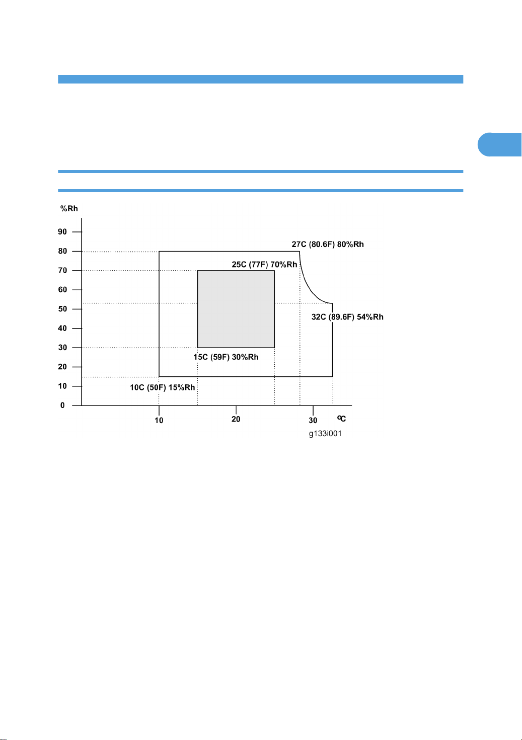
1. Temperature Range: 10°C to 32°C (50°F to 89.6°F)
2. Humidity Range: 15% to 80% RH
3. Ambient Illumination: Less than 1500 lux (do not expose to direct sunlight)
4. Ventilation: 3 times/hr/person or more
5. Do not let the machine get exposed to the following:
1) Cool air from an air conditioner
2) Heat from a heater
6. Do not install the machine in areas that are exposed to corrosive gas.
7. Install the machine at locations lower than 2,500 m (8,200 ft.) above sea level.
8. Install the machine on a strong, level base. (Inclination on any side must be no more than 5 mm.)
9. Do not install the machine in areas that get strong vibrations.
11
Page 13
1. Installation Procedure
1
Machine Level
Front to back: Within 5 mm (0.2")
Right to left: Within 5 mm (0.2")
Machine Space Requirements
• This machine, which uses high voltage power sources, can generate ozone gas. High ozone density
is harmful to human health. Therefore, the machine must be installed in a well-ventilated room.
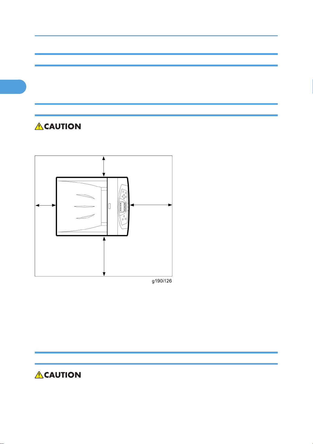
• Left side: Over 50cm (19.7”)
• Rear: Over 10cm (4”)
• Right side: Over 10cm (4”)
• Front: Over 70cm (27.6”)
Put the machine near the power source with the clearance.
Power Requirements
• Insert the plug firmly in the outlet.
• Do not use an outlet extension plug or cord.
12
Page 14

• Ground the machine.
1
1. Input voltage level:
2. 120 V, 60 Hz: More than 11 A
3. 220 V to 240 V, 50 Hz/60 Hz: More than 6 A
4. Permissible voltage fluctuation: ±10 %
5. Do not put things on the power cord.
Installation Requirements
13
Page 15

1. Installation Procedure
1
Optional Unit Combinations
Machine Options
U: User installation, C: CE installation
No. Options Remarks
1 Paper Feed Unit Type 4000 (G392) U Up to x 3
Controller Options
U: User installation, C: CE installation
No. Options Remarks
1 Printer Hard Disk Drive Type 420 (M344) U
2 Memory Unit Type G /128MB (M345) U
3 Memory Unit Type G /256MB (D362) U
4 IEEE1284 Interface Board Type A (B679) U
IEEE802.11a/g Interface Unit Type L (M344)
5
-or-
IEEE802.11a/g Interface Unit Type M (M344)
6 IEEE802.11g Interface Unit Type P (M344) U
7 Gigabit Ethernet Board Type A (874) U
8 Bluetooth Interface Unit (B826) U
9 Camera Direct Print Card Type E (M344) U
11 Data Storage Card Type A (G874) U
12 HDD Encryption Unit Type C (M344) U
13 VM Card Type H (G344) C
U
I/F slot
SD slot 110 Data Overwrite Security Unit (M344) U
SD slot 2
14
Page 16
Printer Installation
1
Printer Installation
Installation Procedure
• Remove the tape from the development units before you turn the main switch on. The development
units can be severely damaged if you do not remove the tape.
• Keep the shipping retainers after you install the machine. You may need them in the future if you
transport the machine to another location.
Unpacking
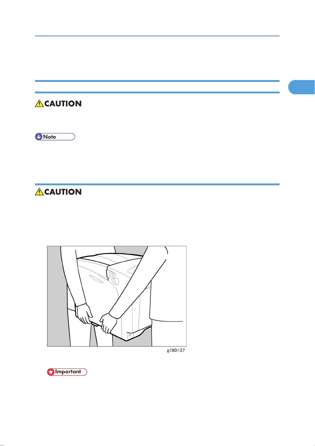
• When lifting the machine, use the inside grips on both sides of the machine.
• If not, the machine could be dropped. This may cause an injury and may damage the machine.
• Place no objects to the left or on the cover.
1. Remove the plastic bag.
2. Lift the machine with two people by using the inset grips on both sides of the machine.
• Do not remove the tapes before placing the machine.
• Lower the machine slowly and carefully, so as not to pinch your hands.
3. Remove the tape from the printer.
15
Page 17
1. Installation Procedure
1
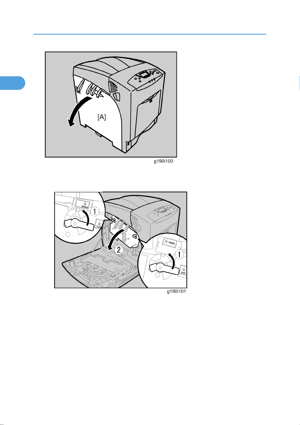
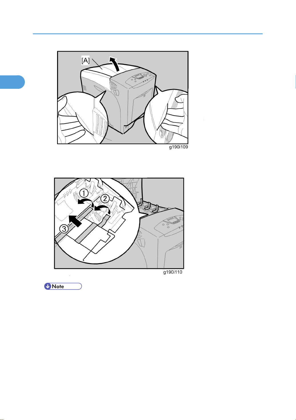
4. Open the left cover [A] of the printer.
5. Turn the two green levers counterclockwise ¬, and then slowly open the inner cover Á
16
Page 18
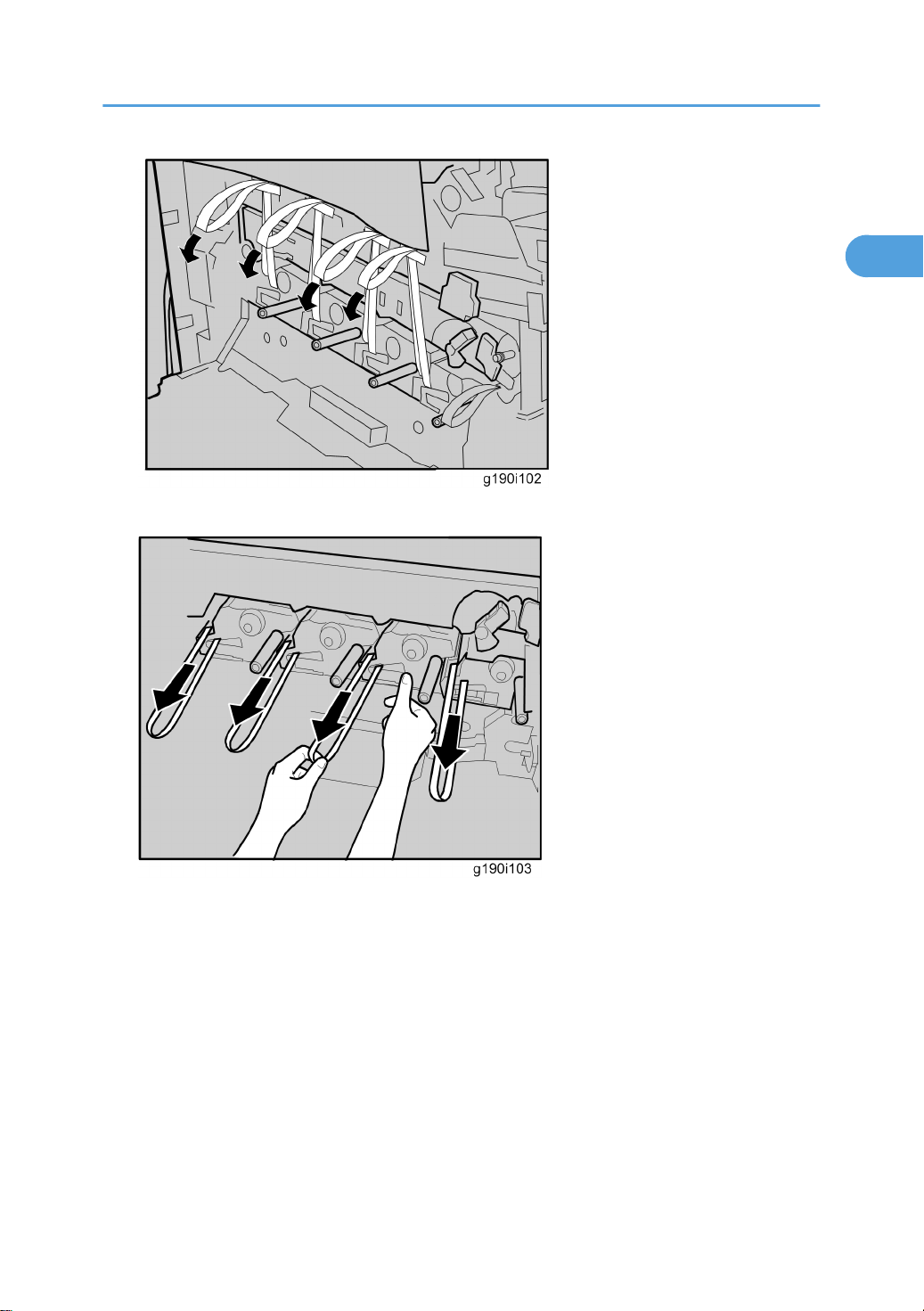
6. Remove the end of the tape from the printer.
1
Printer Installation
7. Remove the four pieces of tape from the PCU in a horizontal direction.
17
Page 19
1. Installation Procedure
1
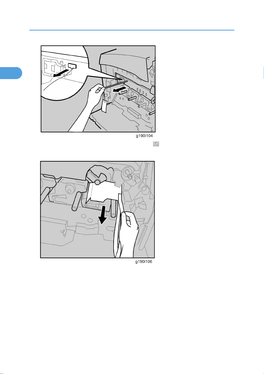
8. Remove the securing pin, as shown, from the transfer unit.
9. Turn the green lever of the transfer unit counterclockwise to unlock the unit.
10. Remove the protective sheet.
18
Page 20
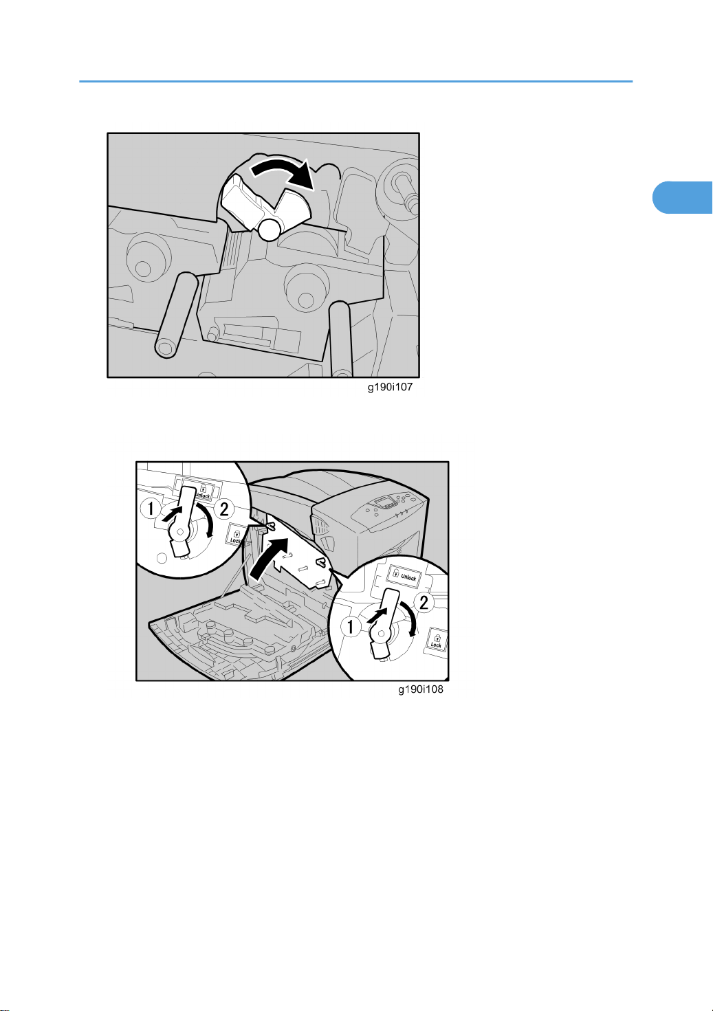
11. Turn the green lever clockwise to lock the unit.
1
Printer Installation
12. Close the inner cover.
13. Push the two green levers ¬ to lock the inner cover, and then turn them clockwise Á.
14. Close the left cover.
19
Page 21
1. Installation Procedure
1
15. Open the top cover [A] by grasping the handles on the left and right sides.
• Be sure to remove the caution sheet, which is attached to the toner compartment.
16. Remove the tapes and cover.
20
Page 22
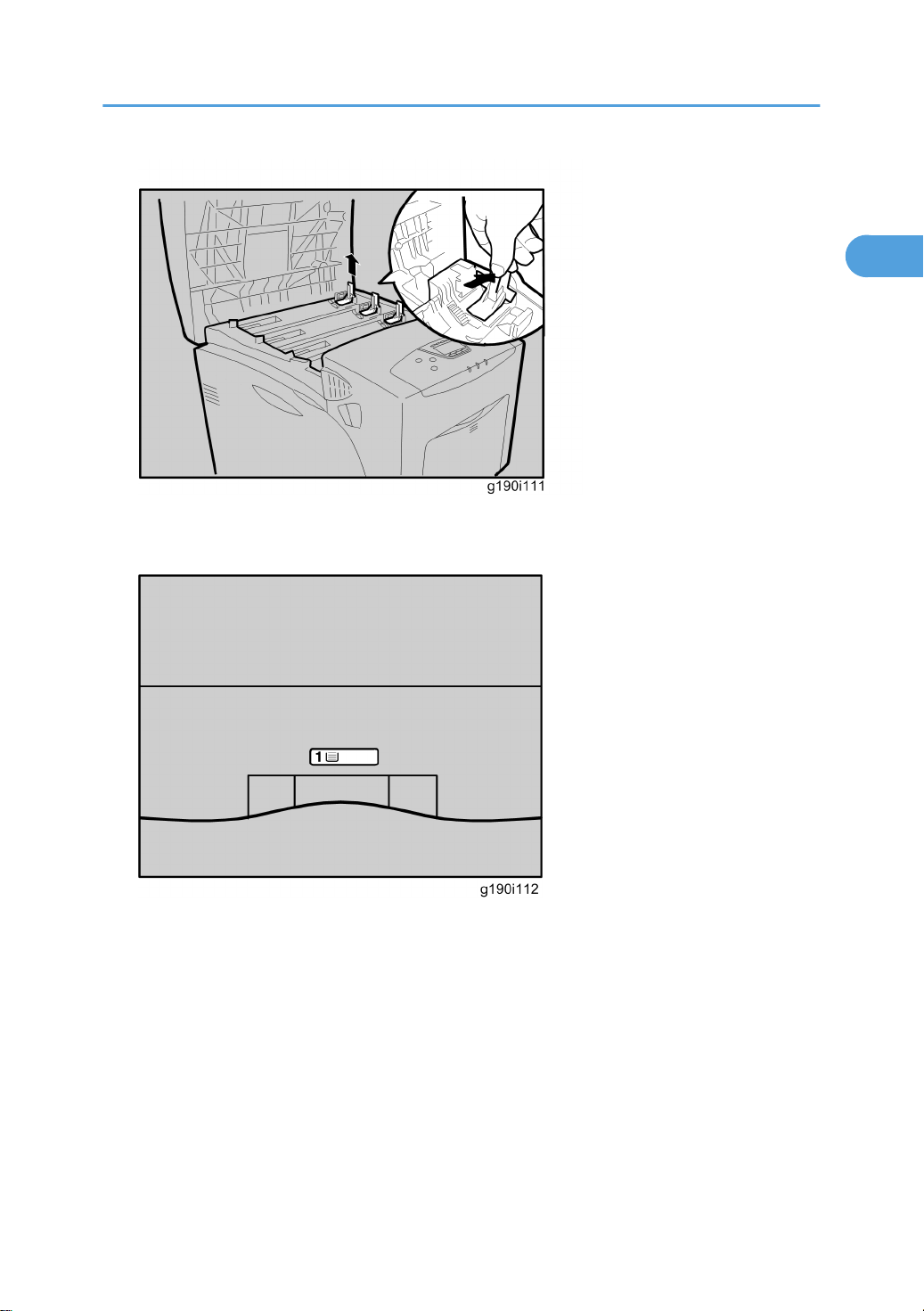
17. Remove the clips protecting the mouths of all four toner compartments.
1
18. Close the top cover.
Printer Installation
19. Put labels “1” on the front of the paper tray.
21
Page 23
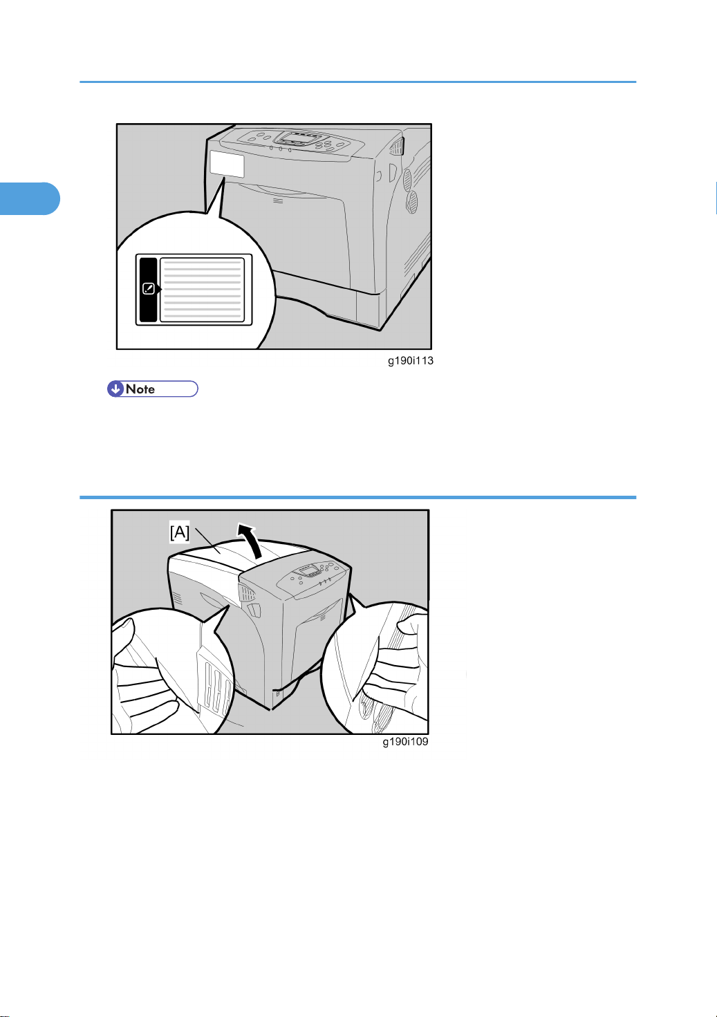
1. Installation Procedure
1
• Be sure to read the label which is attached to the front surface of the printer. This warns you that
ink-jet paper cannot be used with this printer.
Installing the toner
1. Open the top cover [A].
22
Page 24
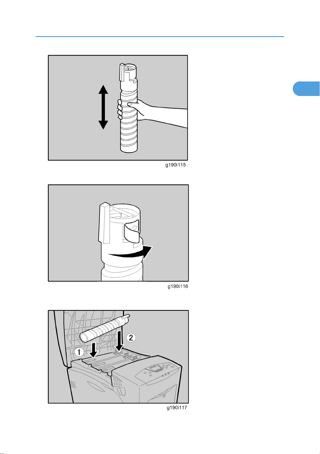
2. Shake the toner bottles up and down seven or eight times before installing.
1
Printer Installation
3. Remove the tape from the toner bottle.
23
Page 25
1. Installation Procedure
1
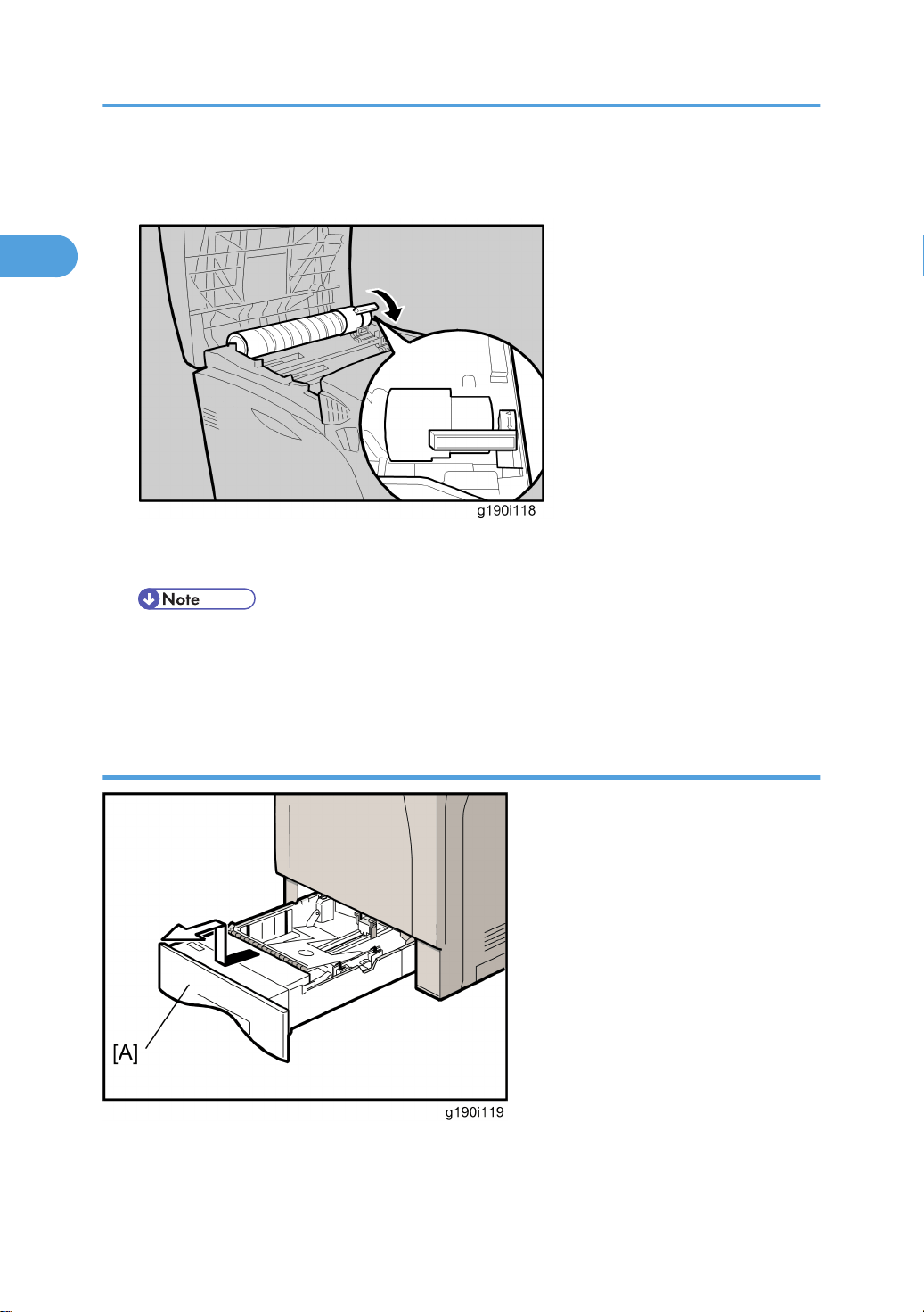
4. Install the yellow toner bottle first. Holding the toner bottle horizontally ¬ with the locking lever on
the upper side, install the toner bottom first, and then move the locking lever to the triangle mark Á.
5. Turn the locking lever to the circle mark. Pull the locking lever toward front side of the printer, until it
locks and clicks into place.
• Do not repeatedly insert and remove toner bottles. This causes toner leakage.
6. Do the same procedure to install the other three bottles: cyan (C), magenta (M), and black (B).
7. Close the top cover.
Loading Paper
1. Pull out tray 1 [A] of the printer until it stops.
2. Lift it slightly, and then pull it out.
24
Page 26
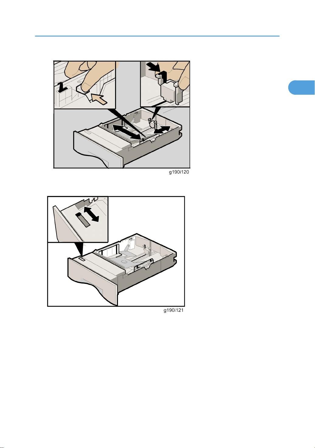
3. Adjust the green clips of the side guide and the end guide to the paper size you want.
1
Printer Installation
4. Move the green switch on the front of the tray to match the type of paper to be loaded. Move the
switch to the left when you load thick paper of 75 g/m2 or more.
25
Page 27
1. Installation Procedure
1
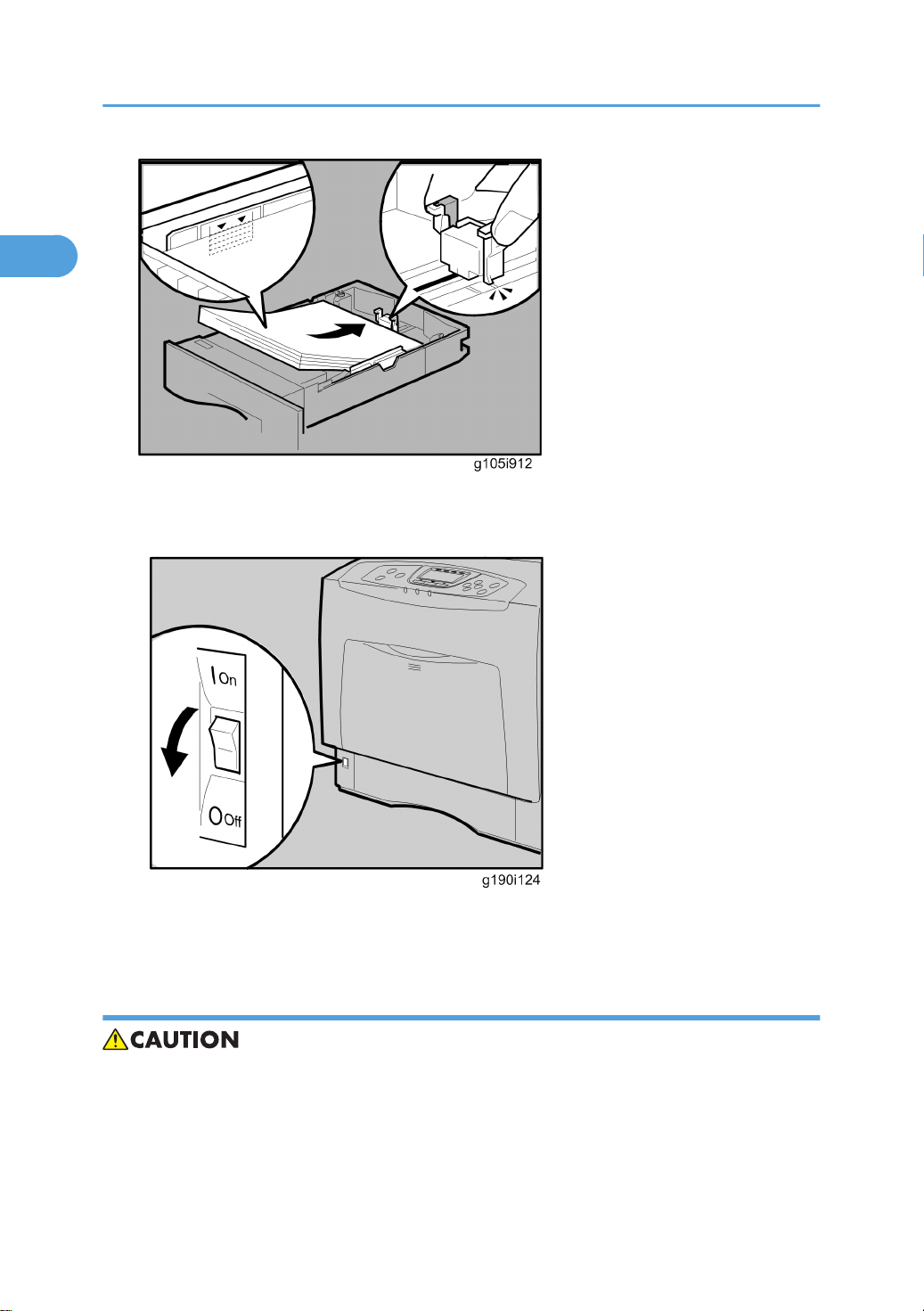
5. Arrange and load a stack of new paper into the tray with the print side up. Make sure that there is no
gap between the paper and the paper guides. Adjust the paper guides to close gaps if necessary.
6. Lift the front of paper tray 1, and slowly slide the paper tray back until it stops. Make sure that the
paper tray is fully inserted, to prevent paper jams.
Turning Power on
• Turn off the power switch whenever you plug in and unplug the power cord.
1. Make sure that the power switch is set to "" (Off).
2. Plug in the machine.
26
Page 28
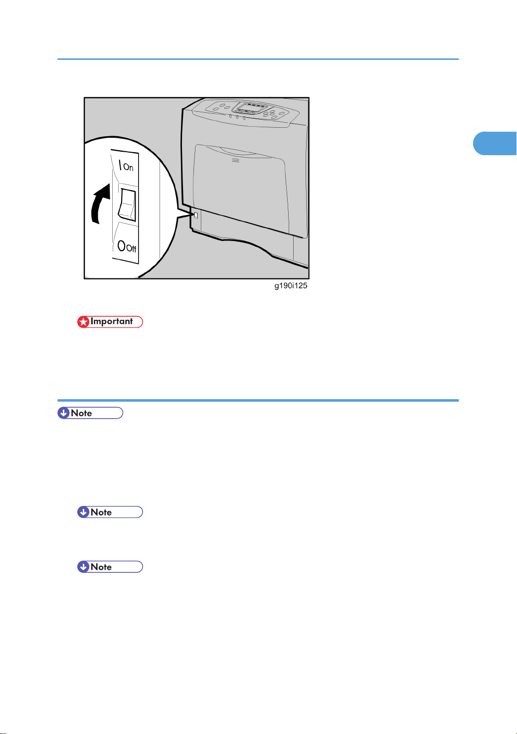
3. Turn on the power switch.
1
Printer Installation
• Do not turn off the power switch until initialization is completed (‘Ready’ appears on the display
when initialization is completed). Otherwise, the machine may malfunction.
Selecting the Panel Display Language
• You can select one of these languages (the default is English): English, German, French, Italian, Dutch,
Swedish, Norwegian, Danish, Spanish, Finnish, Portuguese, Czech, Polish or Hungarian.
• You do not have to do this procedure if you use English. Do this procedure if you want to use a different
language.
1. Turn on the power switch of the printer.
• “Ready” shows on the panel display after the machine warms up.
2. Press the "Menu" key.
• “Menu” shows on the panel display.
3. Press the "" or "" key to select “Language.”
4. Press the "OK" key.
5. Press the "" or "" key to select the language you want.
6. Press the "OK" key.
27
Page 29

1. Installation Procedure
1
7. Press the “Menu” key to return to the initial screen.
Printing the Test Page
1. You can check if the printer works correctly by printing a test page such as the configuration page.
However, you cannot check the connection between the printer and the computer by printing the test
page.
2. Turn on the power switch of the printer.
• “Ready” shows on the panel display after the machine warms up.
3. Press the "Menu" key.
4. Press the "" or "" key to select “List/Test Print.”
5. Press the "OK" key.
6. Press the "" or "" key to select “Config. Page”.
7. Press the "OK" key.
8. The test printing starts shortly after.
9. Press the “Menu” key to return to the initial screen.
10. Turn off the power switch of the printer.
Settings Relevant to the Service Contract
Change the necessary settings depending on the each customer's service contract. For details, refer to
"Meter Click Charge" following this section.
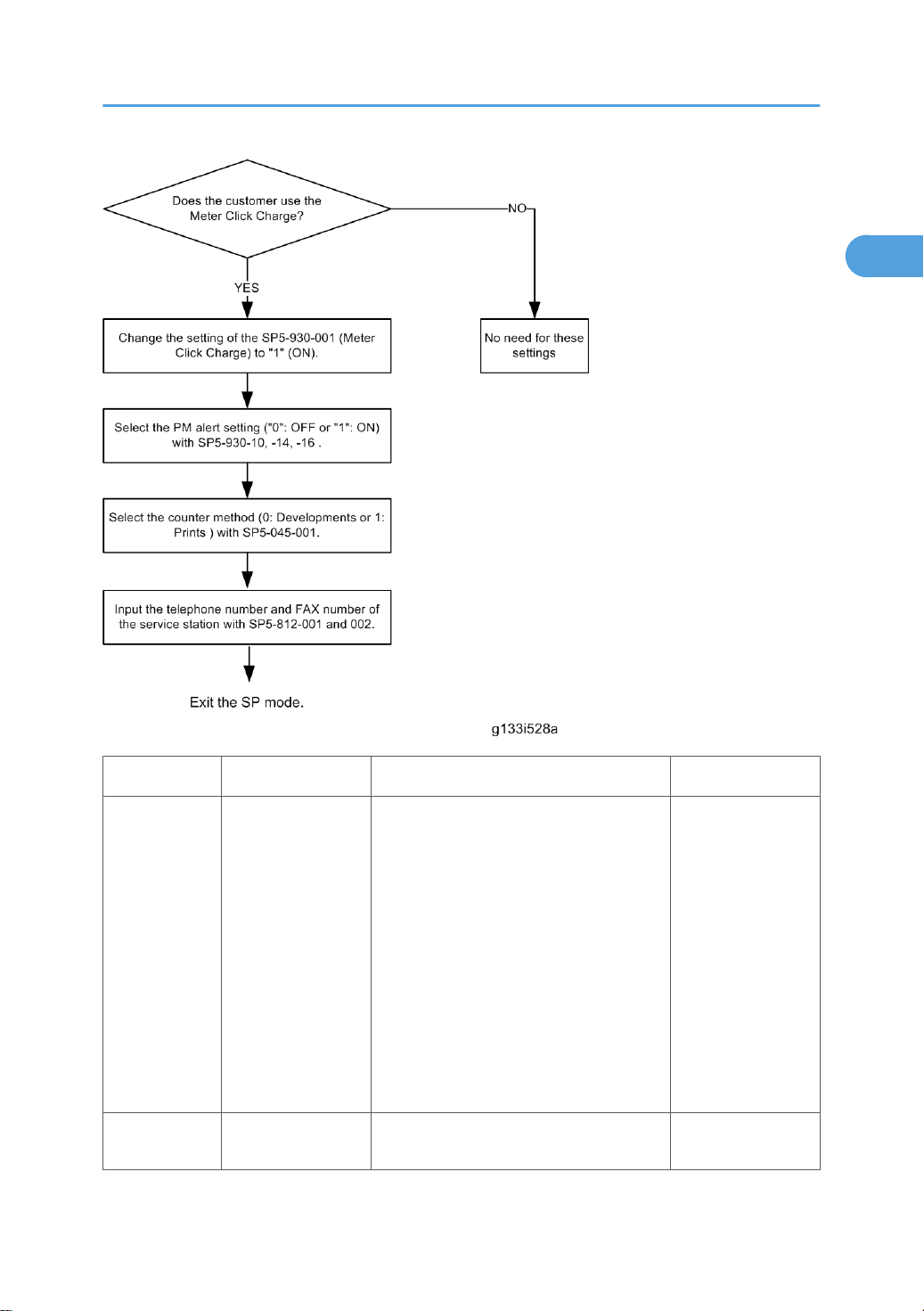
Meter Click Charge
Basically, there are two ways to set up this function.
Meter click change enabled (SP 5-930-001 set to ‘enabled’): The counter can be displayed and printed
by the customer. The technician can then call the customer and ask them to read the counter.
Meter click charge disabled (SP 5-930-001 set to ‘disabled’; this is the default setting): The counter cannot
be displayed or printed by the customer. To check the counter, the technician must print the SMC report
(SP 5-990).
• You must select one of the counter methods (developments/prints) in accordance with the contract
(* SP5-045-001).
28
Page 30
Printer Installation
1
Item SP No. Function Default
Enables or disables Meter Click Charge.
When enabled:
• The counter menu shows
immediately after you push the
Meter Click
Charge
Meter Click
Charge: PCU
SP5-930-001
SP5-930-010
"Menu" key. The "Counter
Method" (SP5-045) sets the type of
the counter.
• You can print the counter from the
counter menu.
When disabled:
• The counter menu does not show.
Enables or disables the PM alert for the
PCUs.
"0": OFF
"1": No alert
29
Page 31

1. Installation Procedure
1
If this SP is enabled, an alert message is
displayed when the PCUs need to be
replaced.
Meter Click
Charge:
Image Transfer
Belt Unit
Meter Click
Charge:
Fusing Unit
Counter
method
Service Tel:
Telephone /
Facsimile
SP5-930-014
SP5-930-016
SP5-045-001
SP5-812-001 and
-002
Enables or disables the PM alert for the
image transfer belt unit.
If this SP is enabled, an alert message is
displayed when the image transfer belt
unit needs to be replaced.
Enables or disables the PM alert for the
fusing unit.
If this SP is enabled, an alert message is
displayed when the fusing unit needs to be
replaced.
Specifies if the counting method used in
meter charge mode is based on
developments or prints.
-001: shows or sets the telephone number
of the service representative.
-002: shows or sets the fax number of the
service station. The number is printed on
the counter list when the "Meter Click
Charge" is enabled. User can send a fax
message with the counter list.
"1": No alert
"1": No alert
“1”: Prints
-
Moving the Machine
This section shows you how to manually move the machine from one floor to another floor. See the section
“Transporting the Machine” if you have to pack the machine and move it a longer distance.
• Remove all trays from the optional paper feed unit.
Transporting the Machine
1. Make sure there is no paper left in the paper trays.
2. Do one of the following:
• Attach shipping tape to the covers and doors.
• Shrink-wrap the machine tightly.
30
Page 32
Options Installation
1
Options Installation
Paper Feed Unit
For details, refer to the “Hardware Guide” for this machine.
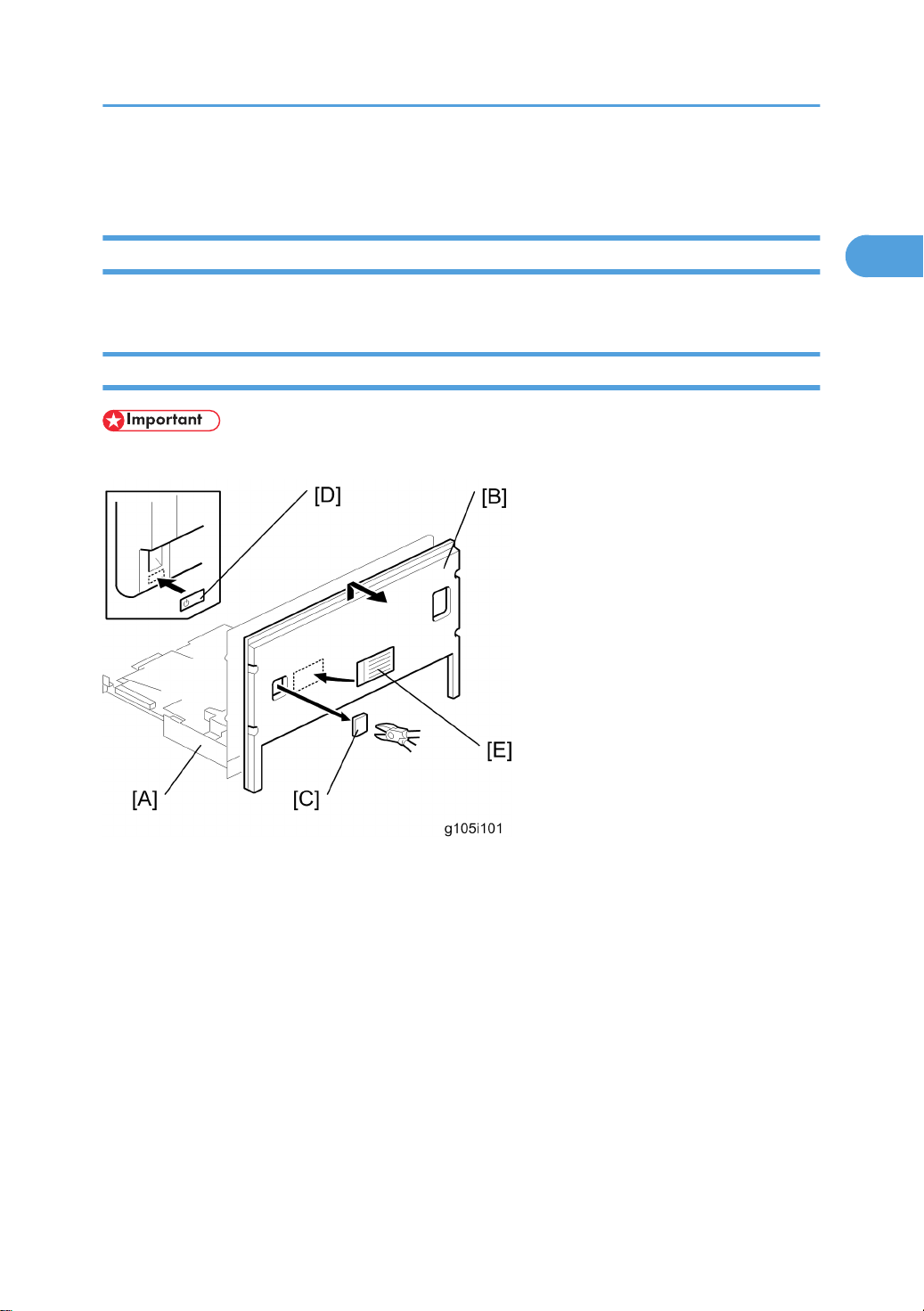
Tray Heater
• Before installing, make sure that the power source rating of the tray heater is same as the machine.
1. Electrical board unit [A] (*: Electrical board unit)
2. Rear cover [B]
3. Rear cover piece [C] for the power supply connector
4. Decal [D]
5. Decal [E]
31
Page 33
1. Installation Procedure
1
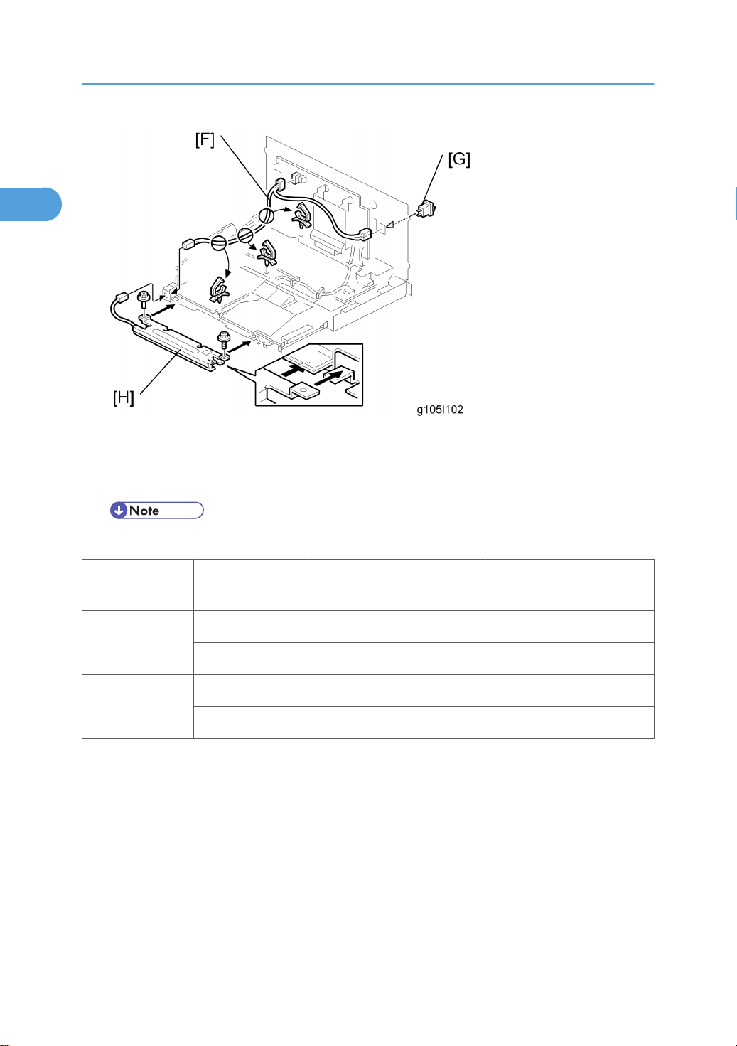
6. Harness [F] ( x 2, x 3)
7. Tray heater switch [G]
8. Tray heater [H] ( x 2, x 1)
• You can adjust the tray heater switch setting with SP5953-001 as shown in the following table.
SP5953-001 Tray heater switch When the Main Power turns on
On No power supply Power supply
0: Off
Off No power supply No power supply
On Power supply Power supply
1: On
Off No power supply No power supply
When the printer is in energy
saver mode
32
Page 34
Controller Options
1
The following options are available for this machine; refer to the “Hardware Guide”.
• Hard Disk Drive
• IEEE1284
• IEEE802.11a/g,g
• Gigabit Ethernet
• Bluetooth
• Camera Direct Print Card
• Data Storage card
• VM Card
The following options are available for this machine; refer to the “Security Guide”.
• Data Overwrite Security Unit
• HDD Encryption Unit
Controller Options
Overview
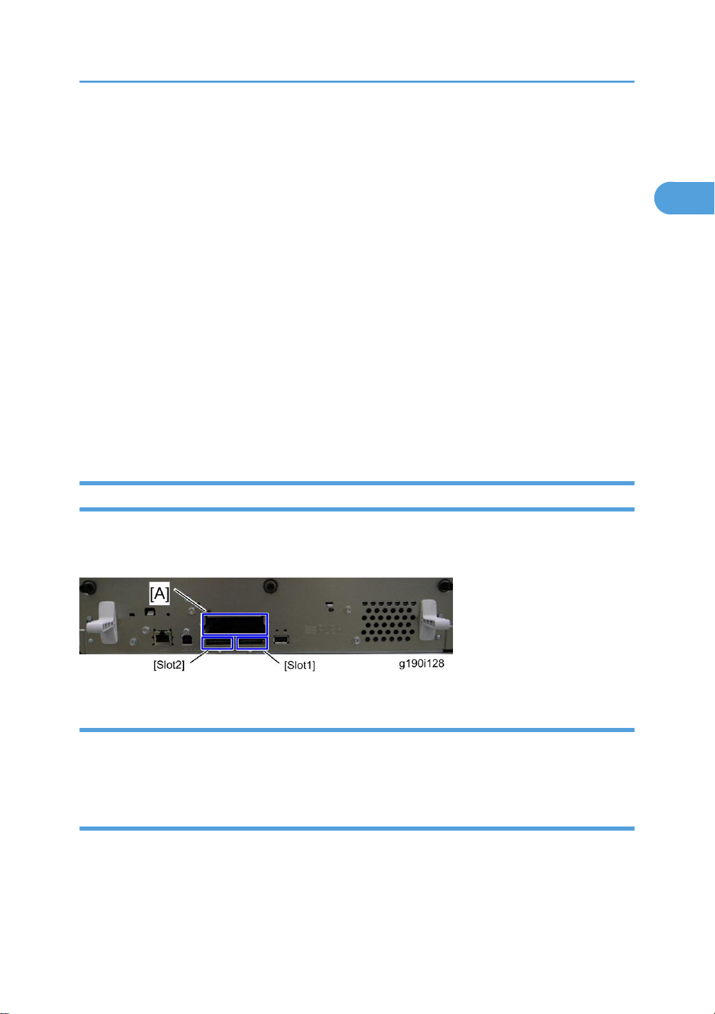
This machine has I/F card slots for optional I/F connections and SD card slots applications.
After you install an option, check that the machine can recognize it.
I/F Card Slots
• Slot A is used for one of the optional I/F connections (only one can be installed): IEEE1284,
IEEE802.11a/g, IEEE802.11g, Bluetooth, Gigabit Ethernet,
SD Card Slots
• SD Slot 1 is used for PictBridge, Data Overwrite Security Unit. Data Storage Card.
• SD Slot 2 is used for installing the VM card or HDD Encryption Unit or one of the optional applications
for service only (for example, updating the firmware).
33
Page 35

1. Installation Procedure
1
SD Card Appli Move
Overview
The service program “SD Card Appli Move” (SP5-873) lets you copy application programs from one SD
card to another SD card.
Do not try to copy the VM card or the HDD encryption unit to another SD card.
You cannot run application programs from Slot 2. However you can move application programs from Slot
2 to Slot 1 with the following procedure.
• Make sure that the target SD card has enough space, and put it in slot 1.
• Enter SP5873 “SD Card Appli Move”.
• Then move the application from the SD Card in Slot 2 to the card in slot 1.
• Do steps 1-2 again if you want to move another application program.
• Exit the SP mode.
Be very careful when you do the SD Card Appli Move procedure:
• The data necessary for authentication is transferred with the application program from an SD card to
another SD card. Authentication fails if you try to use the SD card after you copy the application
program from one card to another card.
• Do not use the SD card if it has been used before for other purposes. Normal operation is not
guaranteed when such an SD card is used.
• Keep the SD card in the storage place (*: NOTE) after you copy the application program from the
card to another card. This is done for the following reasons:
1. The SD card can be the only proof that the user is licensed to use the application program.
2. You may need to check the SD card and its data to solve a problem in the future.
• Refer to “Storing the SD card” at the end of this chapter.
Move Exec
The menu “Move Exec” (SP5-873-001) lets you copy application programs from the original SD card to
another SD card.
• Do not turn ON the write protect switch of the system SD card or application SD card on the machine.
If the write protect switch is ON, a download error (e.g. Error Code 44) occurs during a firmware
upgrade or application merge.
34
Page 36

Controller Options
1
1. Turn the main switch off.
2. Make sure that an SD card is in SD Card Slot 1. The application program is copied to this SD card.
3. Insert the SD card with the application program in SD Card Slot 2. The application program is copied
from this SD card.
4. Turn the main switch on.
5. Start the SP mode.
6. Select SP5-873-001 “Move Exec.”
7. Follow the messages shown on the operation panel.
8. Turn the main switch off.
9. Remove the SD card from SD Card Slot 2.
10. Turn the main switch on.
11. Check that the application programs run normally.
Undo Exec
“Undo Exec” (SP5-873-002) lets you copy back application programs from an SD card to the original
SD card. You can use this program when, for example, you have mistakenly copied some programs by
using Move Exec (SP5-873-001).
• Do not turn ON the write protect switch of the system SD card or application SD card on the machine.
If the write protect switch is ON, a download error (e.g. Error Code 44) occurs during a firmware
upgrade or application merge.
1. Turn the main switch off.
2. Insert the original SD card in SD Card Slot 2. The application program is copied back into this card.
3. Insert the SD card with the application program in SD Card Slot 1. The application program is copied
back from this SD card.
4. Turn the main switch on.
5. Start the SP mode.
6. Select SP5-873-002 “Undo Exec.”
7. Follow the messages shown on the operation panel.
8. Turn the main switch off.
9. Remove the SD card from SD Card Slot 2.
• This step assumes that the application programs in the SD card are used by the machine.
10. Turn the main switch on.
35
Page 37
1. Installation Procedure
1
11. Check that the application programs run normally.
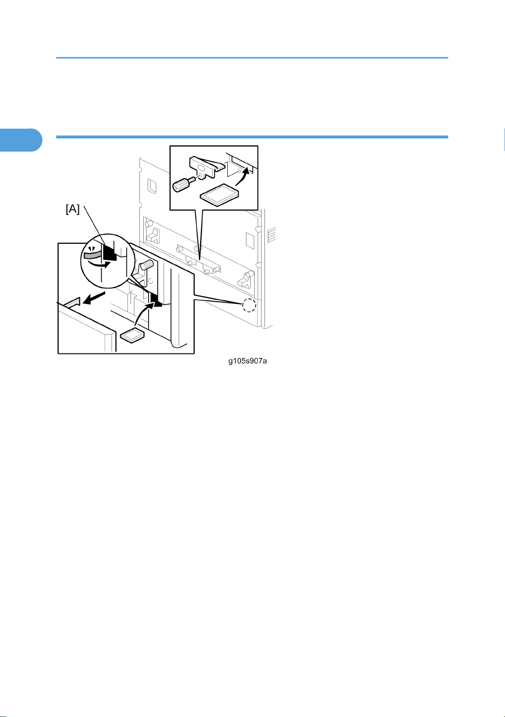
Storing the SD Card
After moving an application, the original SD card must be kept. Keep the SD card in the location [A] shown
in the drawing and fasten it with tape.
36
Page 38

2. Preventive Maintenance
2
User Replaceable Items
The user replaces these items if the service contract requires that the user does some of the PM.
Item Remarks
PCU 50kP (YMC, BK)
Transfer Belt Unit 100kP
Waste Toner Bottle 50kP
Maintenance Kit:
• Fusing Unit
• Transfer Roller
• Paper Feed Roller x 3
• Friction Pad x 3
• Dust Filter x 2
Feed Roller Kit (For tray 4)
• Paper Feed Roller x 1
• Friction Pad x 1
Chart: A4 (LT), 5%
Mode: Continuously Printing
Environment: Recommended temperature and humidity
Yield changes depend on circumstances and print conditions
An error message appears when a maintenance counter gets to the value in the PM table, when the
machine’s default settings are used.
It is not necessary to reset counters for each part if the technician does the PM. The machine detects new
components automatically and resets the necessary counters.
100kP
100kP
37
Page 39

2. Preventive Maintenance
2
Service Maintenance
Recommended Cleaning Procedure
1. Turn off the main switch.
2. Remove the waste toner bottle.
3. Remove the PCUs.
4. Remove the transfer belt unit.
• Do not touch the transfer belt surface.
5. Remove the fusing unit.
6. Remove the standard paper tray.
7. Clean the paper path.
8. Clean all printer rollers with dry cloth only.
• Do not clean the transfer roller.
9. Use a blower brush to clean the laser unit windows.
10. Vacuum the interior of the printer.
11. Carefully clean the area around the transfer roller.
38
Page 40

3. Replacement and Adjustment
3
Before You Start
• Turn off the main power switch and unplug the machine before you do the procedures in this section.
• Remove these before you do the procedures in this section:
• 4 toner bottles (cyan, magenta, yellow, and black)
• Waste toner bottle
• Standard paper tray
39
Page 41

3. Replacement and Adjustment
3
Special Tools and Lubricants
Tools
Item Part Number Description Q’ty
1 B6455010 SD Card 1
2 B6456705 PCMCIA Card Adapter 1
3 B6456820 USB Reader/ Writer 1
4 VSSM9000 Digital Multimeter - FLUKE87 1
5 G0219350 Loop Back Connector - Parallel 1
6 C4019503 20X Magnification Scope 1
7 A2579300 Grease Barrierta – S552R 1
8 52039502 Silicon Grease G-501 1
9 B6795100 Plug - IEEE1284 Type C 1
40
Page 42
Electrical Components
3
Electrical Components
• Before you replace the EGB (Engine Board), the controller, or the NVRAM, print out the SMC reports
(“SP Mode Data” and “Logging Data”).
• After you replace the EGB (Engine Board) or the controller, remove the NVRAM from the old board
and install it on the new board. If the NVRAM on the old board is defective, replace the NVRAM
(* NVRAM Replacement procedure).
Electrical board unit
1. Front door
2. Top cover
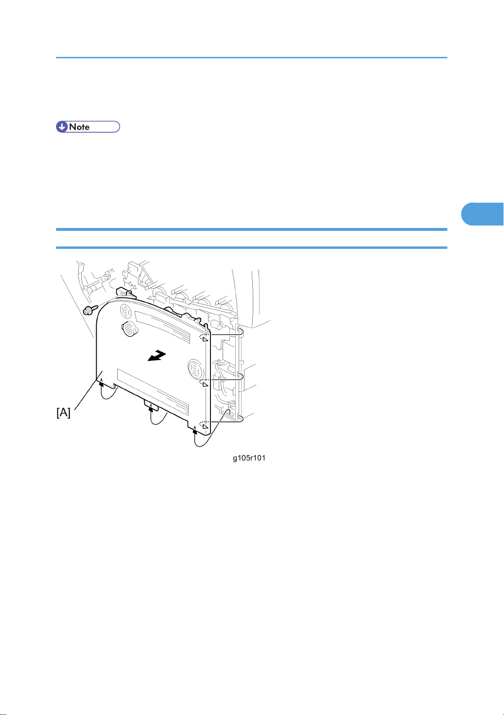
3. Right cover [A] ( x 1)
41
Page 43
3. Replacement and Adjustment
3
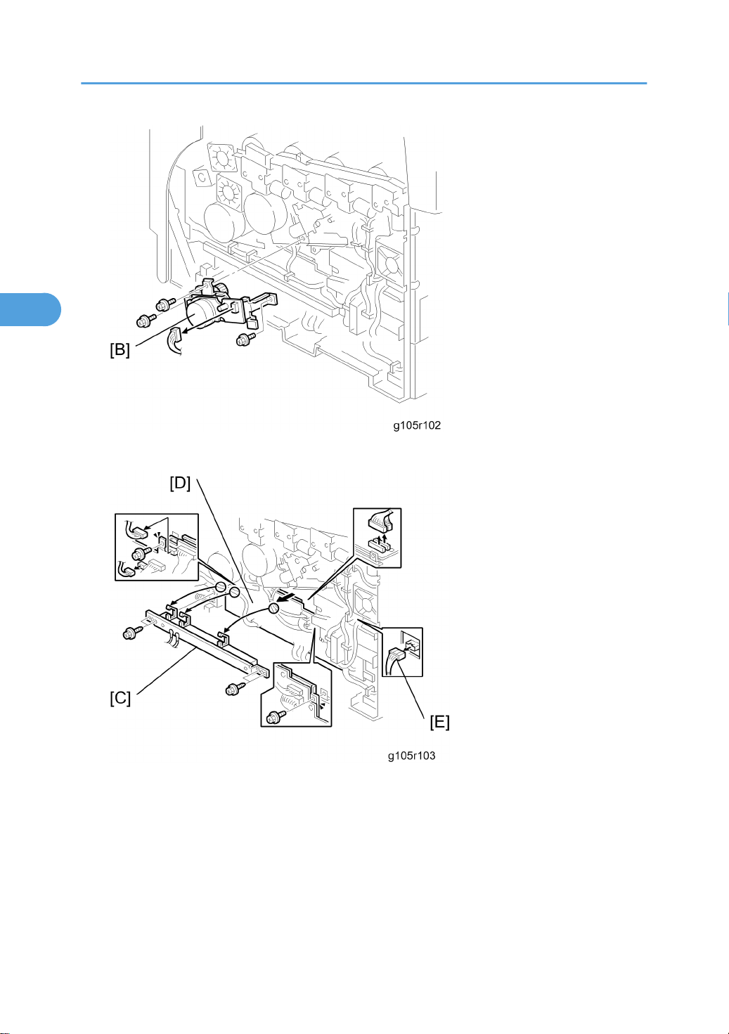
4. Color development motor unit [B] ( x 3, x 1)
5. Side bar [C] ( x 4)
6. IOB (Input/Output Board) [D] ( x 2, x 3)
7. [E] x 1
42
Page 44
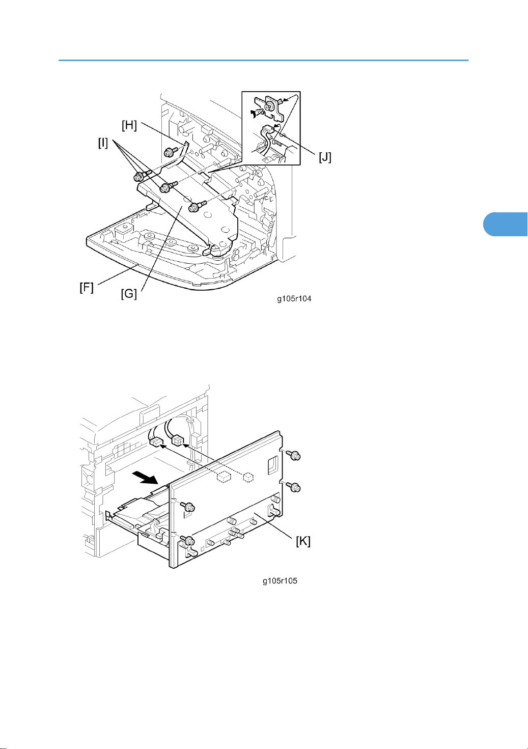
8. Left cover [F]
3
9. Drum positioning plate [G]
Electrical Components
10. Drum positioning plate belt [H] ( x 1)
11. [I] x 3, [J] x 1
12. Electrical board unit [K] ( x 4, x 2)
43
Page 45
3. Replacement and Adjustment
3
IOB (Input/Output Board)
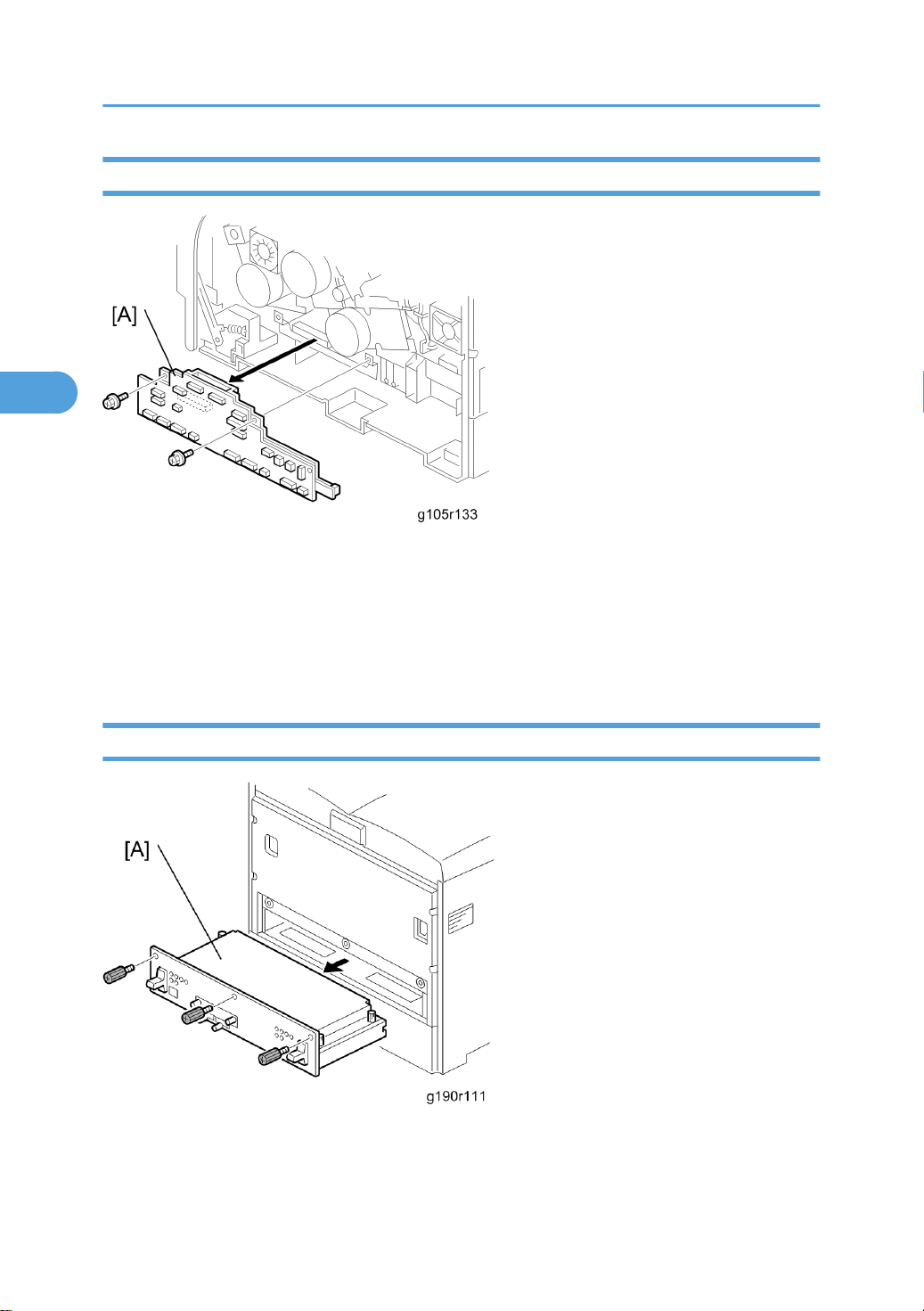
1. Front door
2. Top cover
3. Right cover (* Electrical board unit)
4. Side bar (* Electrical board unit)
5. IOB [A] ( x 2, x all)
Controller Board
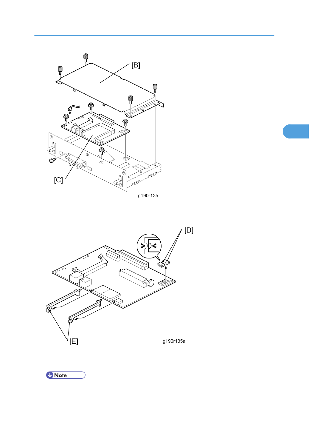
1. Controller unit [A] ( x 3)
44
Page 46
Electrical Components
3
2. Controller unit cover [B] ( x 4)
3. Controller board [C] ( x 5, x 1)
4. Two NVRAMs [D]
5. Two rails [E]
• Removed NVRAMs musrt be installed on the new board.
45
Page 47

3. Replacement and Adjustment
3
• Keep NVRAMs away from objects that can cause static electricity. The data in NVRAMs can be
corrupted by static electricity.
• Make sure the NVRAM is correctly installed on the board. A half-disk is engraved on one side
of the NVRAM, and a guide mark is on one side of the NVRAM slot. When you install the
NVRAM, the half-disk and the guide mark must be on the same side.
Installing the new NVRAM
When the NVRAM on the controller board is detective, you must replace the detective NVRAM with a new
NVRAM.
1. Controller board (see Controller Board)
2. Remove the defective NVRAM.
3. Install the new NVRAM on the controller board.
4. Reassemble the machine.
5. Plug in and turn on the main power
6. Set the date and time with the timer setting in the UP (Maintenance > Menu) after installing a new
controller board.
• If the date and time setting is not done, WebImage Monitor cannot be used.
46
Page 48
PSU (Power Supply Unit) Board
3
Electrical Components
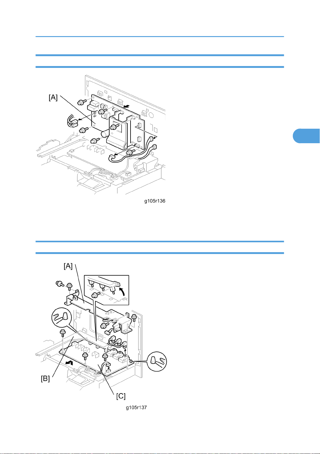
1. Electrical boards unit (* Electrical board unit)
2. PSU board [A] ( x 6, x 5)
High Voltage Power Supply Board 1
47
Page 49
3. Replacement and Adjustment
3
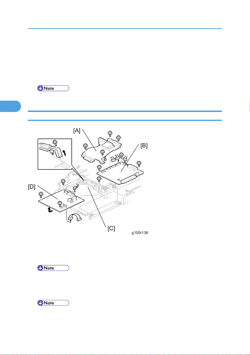
1. Electrical board unit (* Electrical board unit)
2. PSU board (* PSU (Power Supply Unit) Board)
3. Electrical board unit frame [A] ( x 4)
4. High voltage terminal plate [B] ( x 1)
5. High voltage power supply board 1 [C] ( x 4, x 4, stand offs x 2).
• Make sure that each high voltage terminal is connected securely after you replace this board.
EGB (Engine Board) and High Voltage Power Supply Board 2
1. Electrical board unit (* Electrical board unit)
2. EGB shield [A] ( x 3, x 1)
3. EGB [B] ( x 4, x 4)
• Remove the NVRAM from the old board. Then install it on the new board.
4. High voltage terminal plate [C] ( x 1)
5. High voltage power supply board 2 [D] ( x 3, x 2)
• Make sure that each high voltage terminal is connected securely after you replace this board.
48
Page 50
Electrical Components
3
• Keep NVRAMs away from objects that can cause static electricity. The data in NVRAMs can be
corrupted by static electricity.
• Make sure the NVRAM is correctly installed on the board. A half-disk is engraved on one side
of the NVRAM, and a guide mark is on one side of the NVRAM slot. When you install the
NVRAM, the half-disk and the guide mark must be on the same side.
LCD Panel
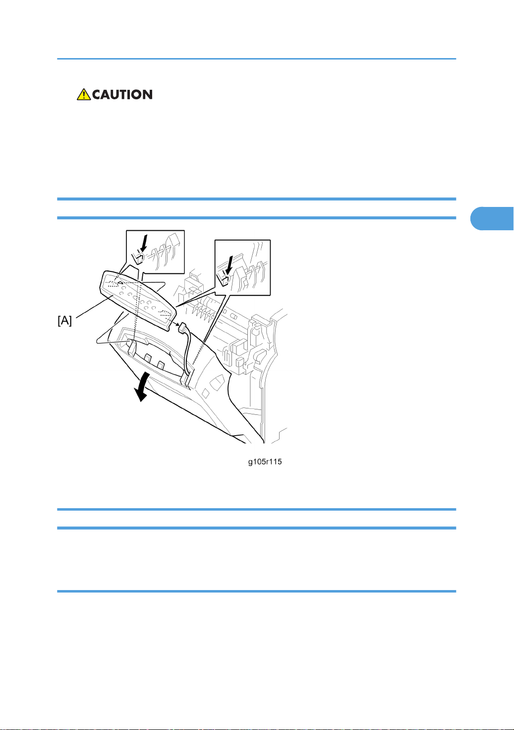
1. LCD panel [A] ( x 1)
NVRAM Replacement Procedure
Make sure that you have the SMC report (factory settings) before beginning the following procedure.
NVRAM on the EGB (Engine Board)
For this procedure, you must know the device number and the destination code (* step 8).
1. Start the SP mode.
2. Use SP5-990 to print out the SMC reports (“SP Mode Data” and “Logging Data”) if possible.
3. Turn off the main power switch and unplug the power cord.
49
Page 51

3. Replacement and Adjustment
3
4. Replace the NVRAM on the EGB and reassemble the machine.
5. Plug in the power cord.
6. Turn on the main power switch.
7. Start the SP mode.
8. Contact your supervisor to enter the machine’s device number.
• SC542 may be displayed until the machine’s device number and destination code are
programmed properly.
9. Turn the main power switch off and on.
10. Start the SP mode.
11. Use SP5-801-002 to reset the engine settings.
12. Reset the meter charge settings (SP5-930-001).
13. Enter the SP mode changes previously made at the factory and the field.
14. Replace all maintenance kits with new ones.
NVRAM on the Controller
1. Start the SP mode.
2. Use SP5-990 to print out the SMC reports (“SP Mode Data” and “Logging Data”) if possible.
3. Use SP5-824 to upload the NVRAM data if possible.
4. Turn off the main power switch and unplug the power cord.
5. Replace the NVRAM on the controller and reassemble the machine.
6. Plug in the power cord.
7. Turn on the main power switch.
8. Start the SP mode.
9. Use SP5-825 to download the NVRAM data if possible. If it can be done, the following steps are not
required.
10. Use Memory Clear (SP5-801) to reset this data:
• SCS (SP5-801-003)
• PRT (SP5-801-008)
• NCS (SP5-801-011)
11. Do Counter Clear (SP7-810).
12. Make these contract-related settings:
• Counter Method (SP5-045)
50
Page 52

Electrical Components
3
• Telephone Number Setting > Fax Telephone Number (SP5-812-002) if the meter charge mode
(SP5-930-001) is “ON” (enabled)
13. Enter the SP mode changes previously made at the factory and the field.
NVRAMs on the EGB and Controller
For this procedure, you must know the device number and the destination code (* step 10).
1. Start the SP mode.
2. Use SP5-990 to print out the SMC reports (“SP Mode Data” and “Logging Data”) if possible.
3. Use SP5-824 to upload the NVRAM data if possible.
4. Turn off the main power switch and unplug the power cord.
5. Replace the NVRAMs on the EGB and the controller, and reassemble the machine.
6. Plug in the power cord.
7. Turn on the main power switch.
8. Start the SP mode.
9. Use SP5-825 to download the NVRAM data if possible.
10. Contact your supervisor to enter the machine’s device number.
• SC542 may be displayed until the machine’s device number and destination code is
programmed properly.
11. Turn the main power switch off and on.
12. Start the SP mode.
13. Use SP5-801-002 to reset the engine settings.
14. Use Memory Clear (SP5-801) to reset this data:
• SCS (SP5-801-003)
• PRT (SP5-801-008)
• NCS (SP5-801-011)
15. Do Counter Clear (SP7-810).
16. Reset the meter charge settings (SP5-930-001).
17. Make these contract-related settings:
• Counter Method (SP5-045)
• Telephone Number Setting > Fax Telephone Number (SP5-812-002)
18. Enter the SP mode changes previously made at the factory and the field.
19. Replace all maintenance kits with new ones.
51
Page 53
3. Replacement and Adjustment
3
Laser Optics
• Turn off the main power switch and unplug the printer before you do the procedures in this section.
Laser beams can cause serious eye injury.
Caution Decal Locations
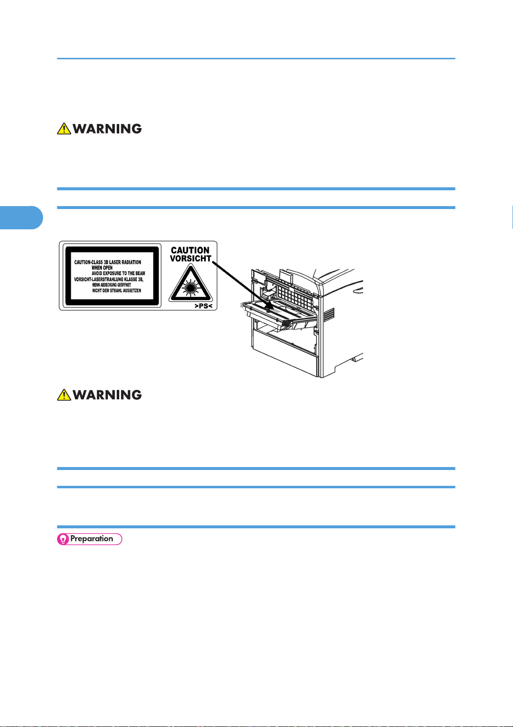
The caution decal is attached as shown below
52
• Make sure to turn off the main power switch and disconnect the power plug from the power outlet
before you do any disassembly or adjustment of the laser unit. This printer uses a class 3B laser beam
with a wavelength of 648 to 663 nm and an output of 9 mW. The laser can cause serious eye injury.
LD Unit
Replacement
• Print the SMC report with SP 5990 2 before you replace the LDU.
Page 54
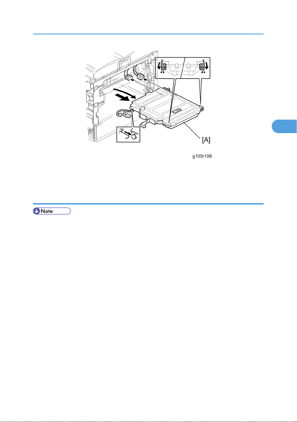
1. Electrical board unit (* Electrical board unit)
3
2. LDU [A]
Laser Optics
Color Registration Adjustment
• You must manually do the color registration adjustment after you install the new LDU.
• When the polygon mirror motor or LDB unit is defective, only replace the defective parts. At this time,
if only the motor is changed it is not necessary to do this adjustment procedure.
1. Print the SMC report with SP 5990 2 before you replace the LDU. Find the values for SP 2181 1, SP
2181 11, 2181 21, and 2181 31.
2. Do SP 2111 2 (Pro. Position Adj > Execute) to roughly adjust the line position after you install the new
LDU. “Result = OK” shows on the LCD if this is done correctly. If not, do it again until you get “OK”.
3. Do SP2111 3 (Skew Adjust. > Execute) to measure the skew values for each color. “Result = OK”
shows on the LCD if this is done correctly. If not, do it again until you get “OK”.
4. Check the skew values with SP 2181: Then write down the values. (You can also check these if you
print the SMC report again with SP 5990 2. The values will probably be different from the values on
the report that you printed in step 1.)
• SP 2181 1 for black skew
• SP 2181 11 for magenta
• SP 2181 21 for cyan
• SP 2181 31 for yellow
53
Page 55
3. Replacement and Adjustment
3
5. Open the left cover
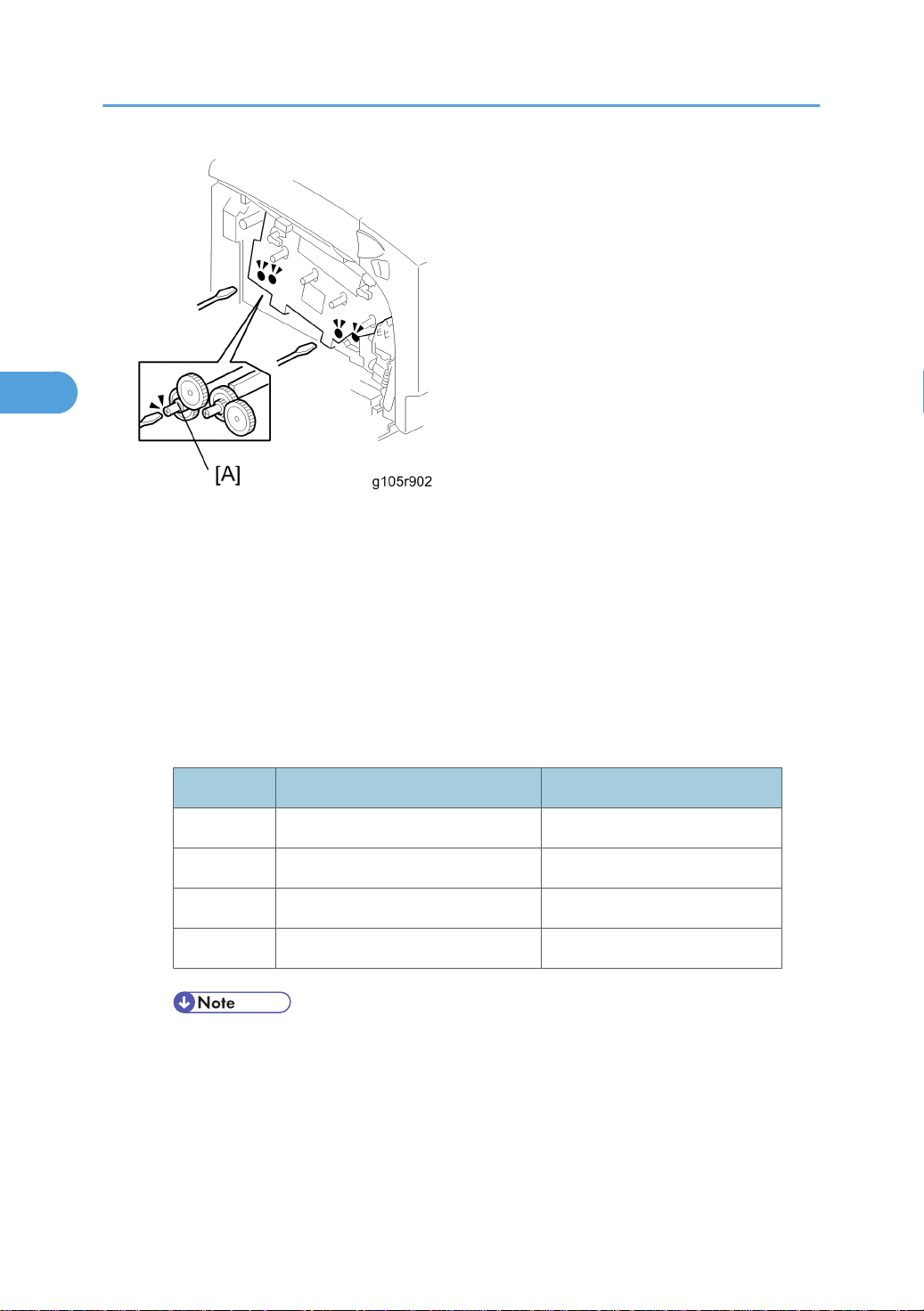
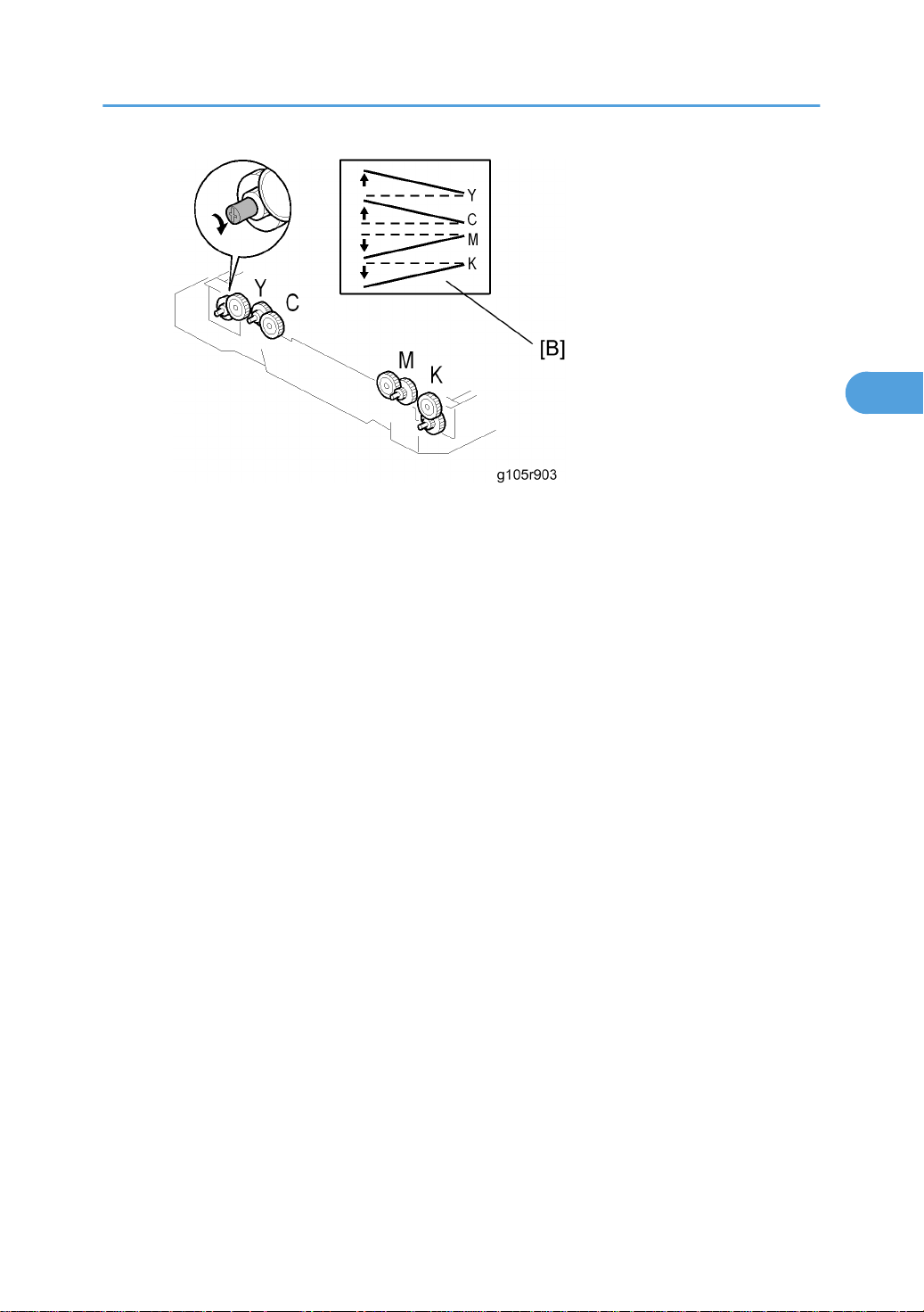
6. Adjust the skew adjustment cam [A] for each color with a screwdriver. You must adjust the skew values
for each color until they are all the same as the value for magenta that you found in step 1, before
you replaced the LDU.
• For example: If the new value for K (after step 4) is -300 and the old value for magenta (in step
1) is –250, you must adjust the skew for K until it is -250.
• Turn the cam as shown in the “Cam Rotation Direction” column below to increase the skew value.
• Turn it in the opposite direction from this to decrease the skew value.
• “Adjustment value” shows the change when you turn the cam one click.
Color Cam Rotation Direction Adjustment Value
Yellow CW 14 μm
Cyan CW 10 μm
Magenta CCW 10 μm
Black CCW 10 μm
• The adjustment values in the table are not exact values. These are approximate values.
• CW: Clockwise, CCW: Counter-clockwise
54
Page 56
Laser Optics
3
• The diagram shows the effect on line skew [B] when you turn the cam in a counter clockwise
direction.
7. Close the left cover. Then measure the skew values again with SP 2111 3. (To do this, repeat step 3.)
• If these are close to the value for magenta that you found in step 1 (within one click in the above
table), go to the next step. If not, do SP 2111 3 again until you get a good result.
8. Do SP 2111 1 to finely adjust the line position for each color.
• Try SP 2111 2 if “Result = OK” does not show.
9. When you get “Result = OK”, this adjustment is completed.
55
Page 57
3. Replacement and Adjustment
3
LDB
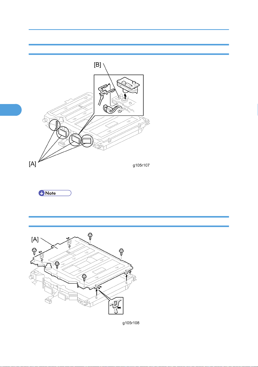
1. LDU (* LD unit)
2. LDB [A] ( x 2)
• Make sure that the spring plate [B] holds the LDB unit.
Polygon Mirror Motor
1. LDU (* LD unit)
56
Page 58
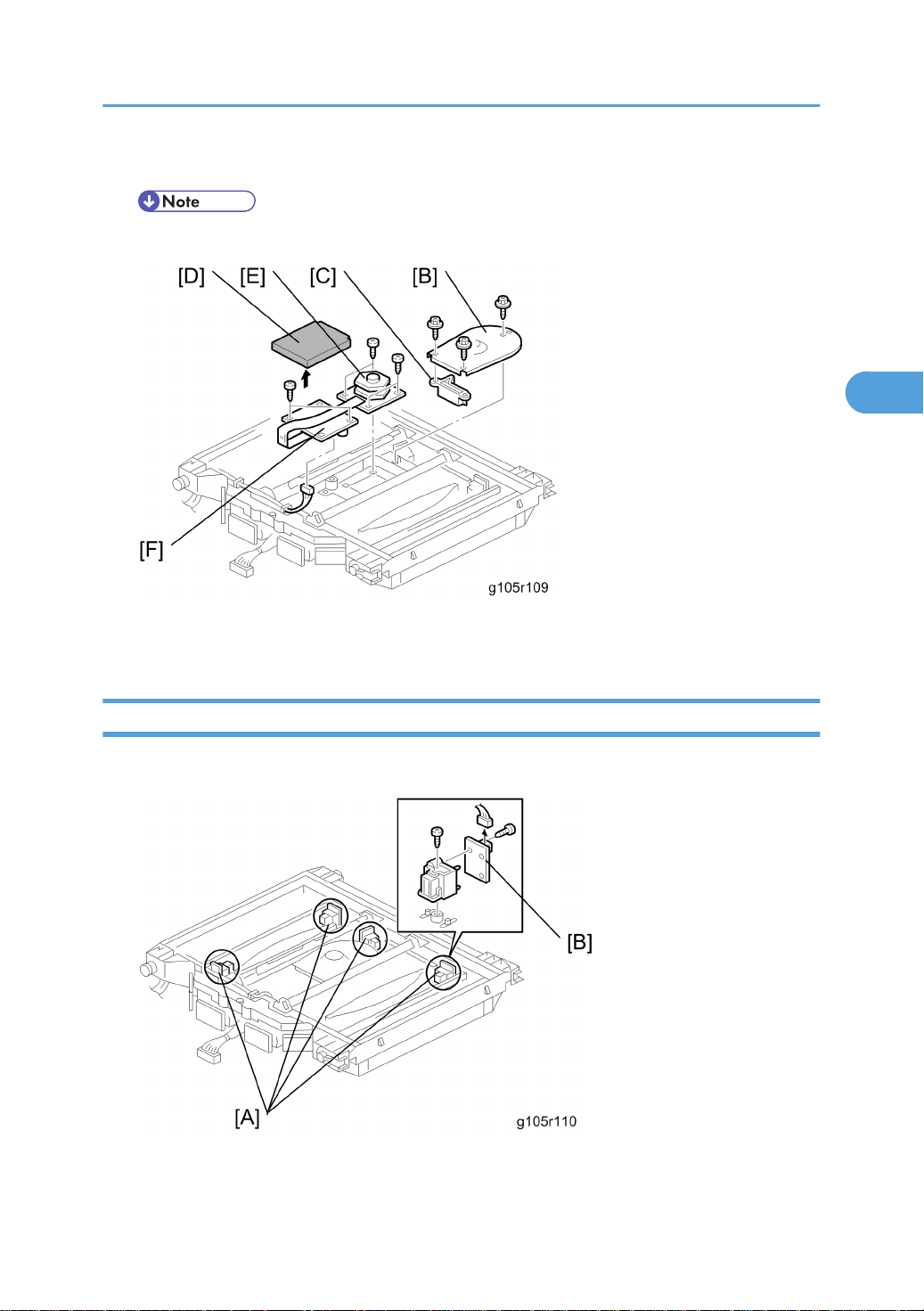
2. Top cover [A] ( x 5, tabs x 4)
3
• Do not touch the mirrors. Clean with an optics cloth if you touch the mirrors.
Laser Optics
3. Polygon motor cover [B] ( x 3), shading plate [C], sponge [D]
4. Polygon mirror motor [E] ( x 4), drive board [F] ( x 2, x 1, 1 flat cable)
Laser Synchronizing Detector Boards
1. LDU (* LD unit)
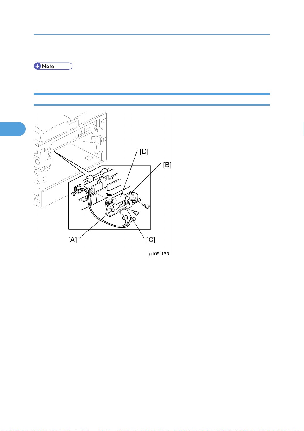
2. Top cover
3. Synchronizing detector board unit [A] ( x 1)
57
Page 59
3. Replacement and Adjustment
3
4. Synchronizing detector board [B] ( x 1, x 1)
• Do not touch the mirrors. Clean with an optics cloth if you touch the mirrors.
LDU Shutter Motor Unit and Sensor
1. Electrical board unit (* Electrical board unit)
2. LDU (* LD unit)
3. LDU shutter motor unit [A] ( x 2, x 2, x 1)
4. Slide up the gear [B] ( x1).
5. LDU shutter sensor [C]
6. LDU shutter motor [D] ( x 2, x 1)
58
Page 60
Laser Optics
3
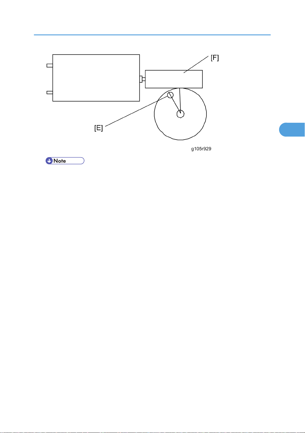
• To do this, place the projection [E] of the gear as shown in the diagram below. The worm gear
[F] must turn.
59
Page 61
3. Replacement and Adjustment
3
Paper Feed
Paper Feed Roller
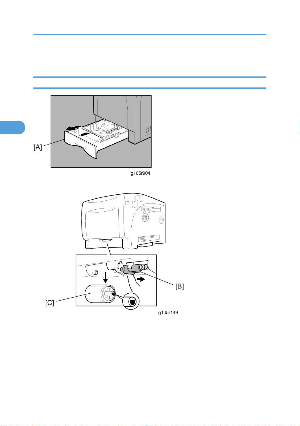
1. Standard tray [A]
2. Slide the side roller holder [B]
3. Paper feed roller [C]
60
Page 62
Paper Friction Pad
3
1. Standard tray (* Paper feed roller)
Paper Feed
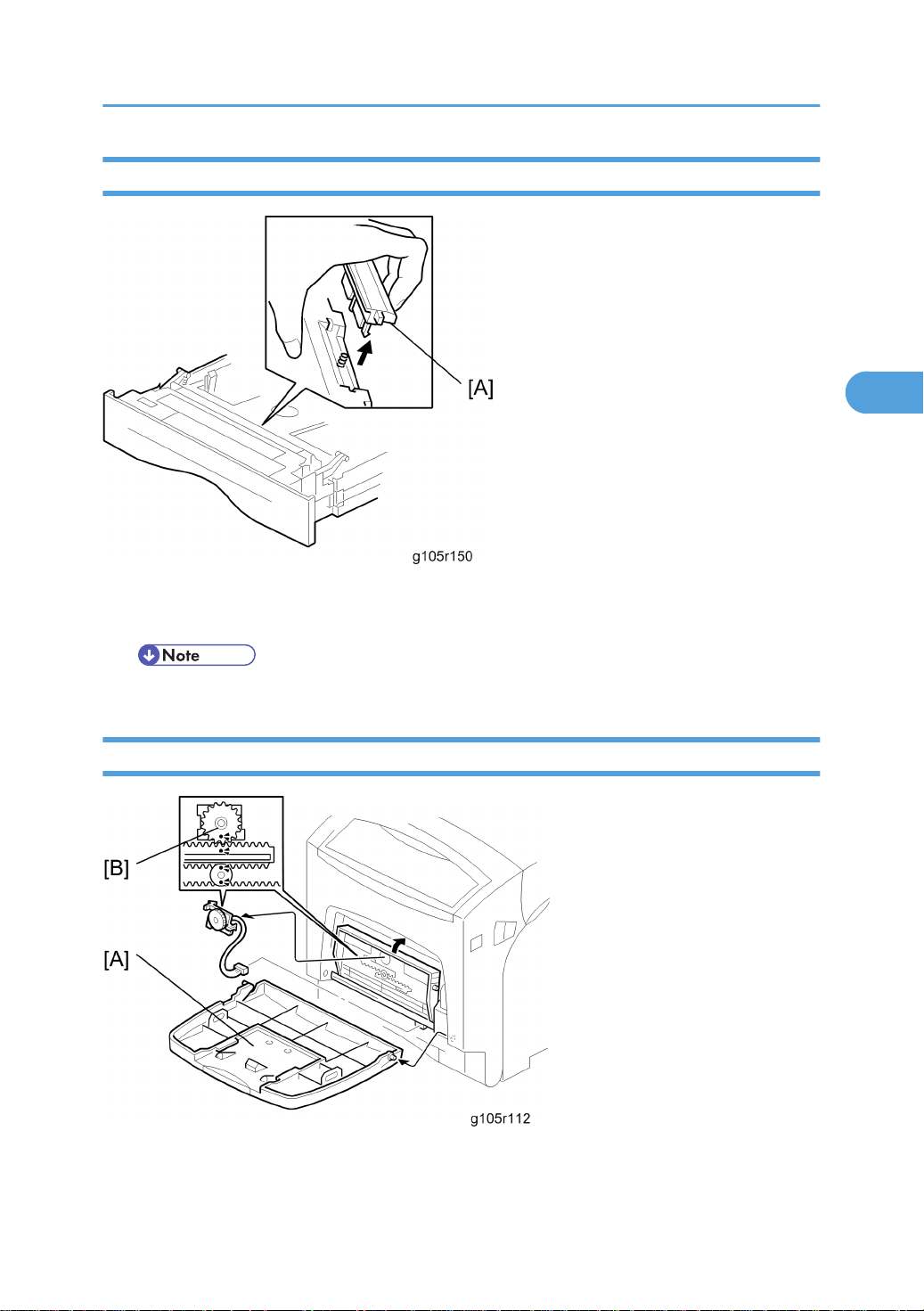
2. Paper friction pad [A]
• Make sure that the paper friction pad stick is put through the spring when you reassemble it.
By-Pass Paper Size Sensor
1. By-pass tray cover [A]
2. By-pass paper size sensor [B] ( x 1)
61
Page 63
3. Replacement and Adjustment
3
By-Pass Feed Roller, Friction Pad
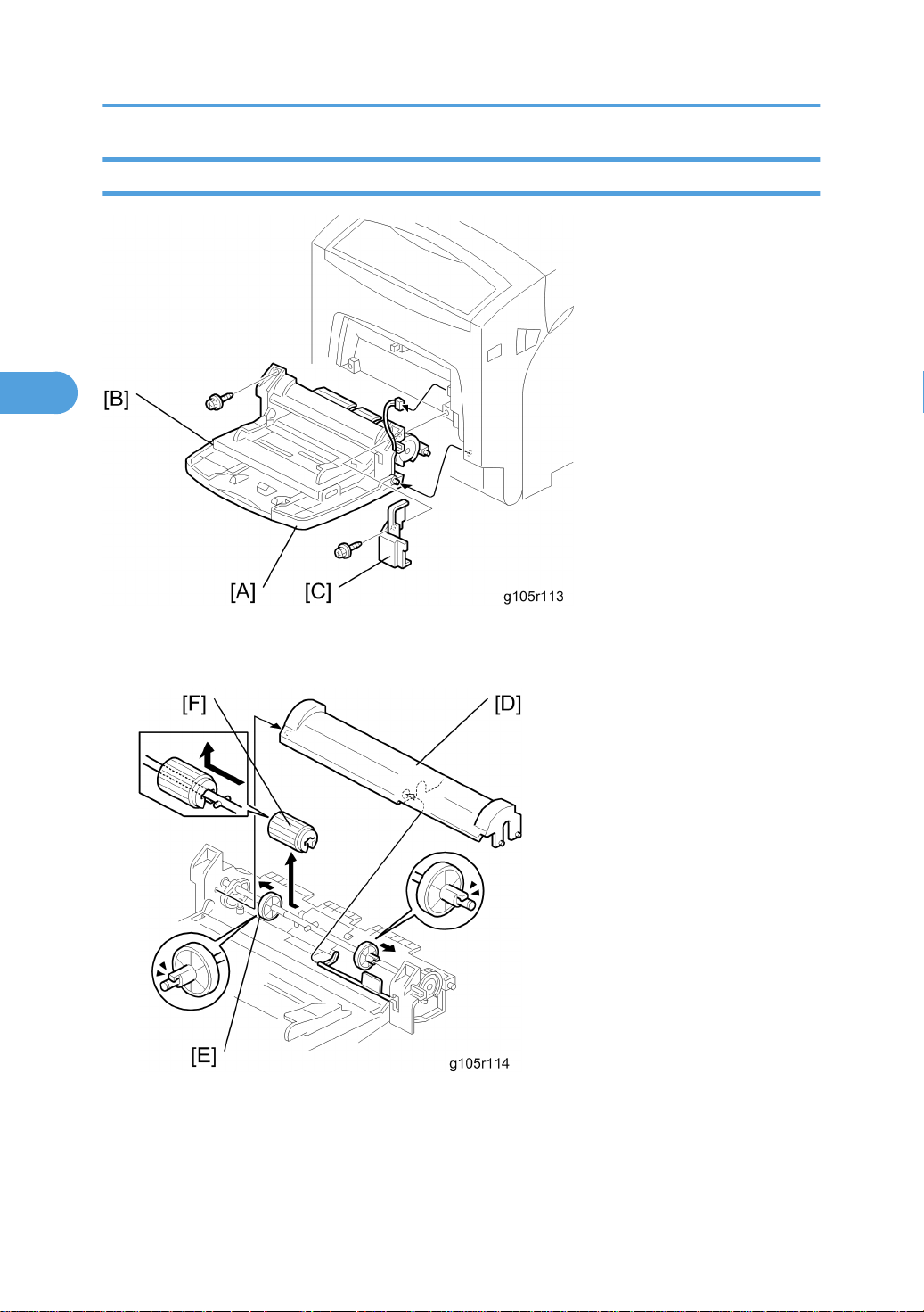
1. By-pass tray cover [A]
2. By-pass tray [B] ( x 2, x 1) and the harness cover [C]
3. By-pass feed shaft cover [D]
4. Move the holding roller left [E]
5. By-pass feed roller [F]
62
Page 64
Paper Feed
3
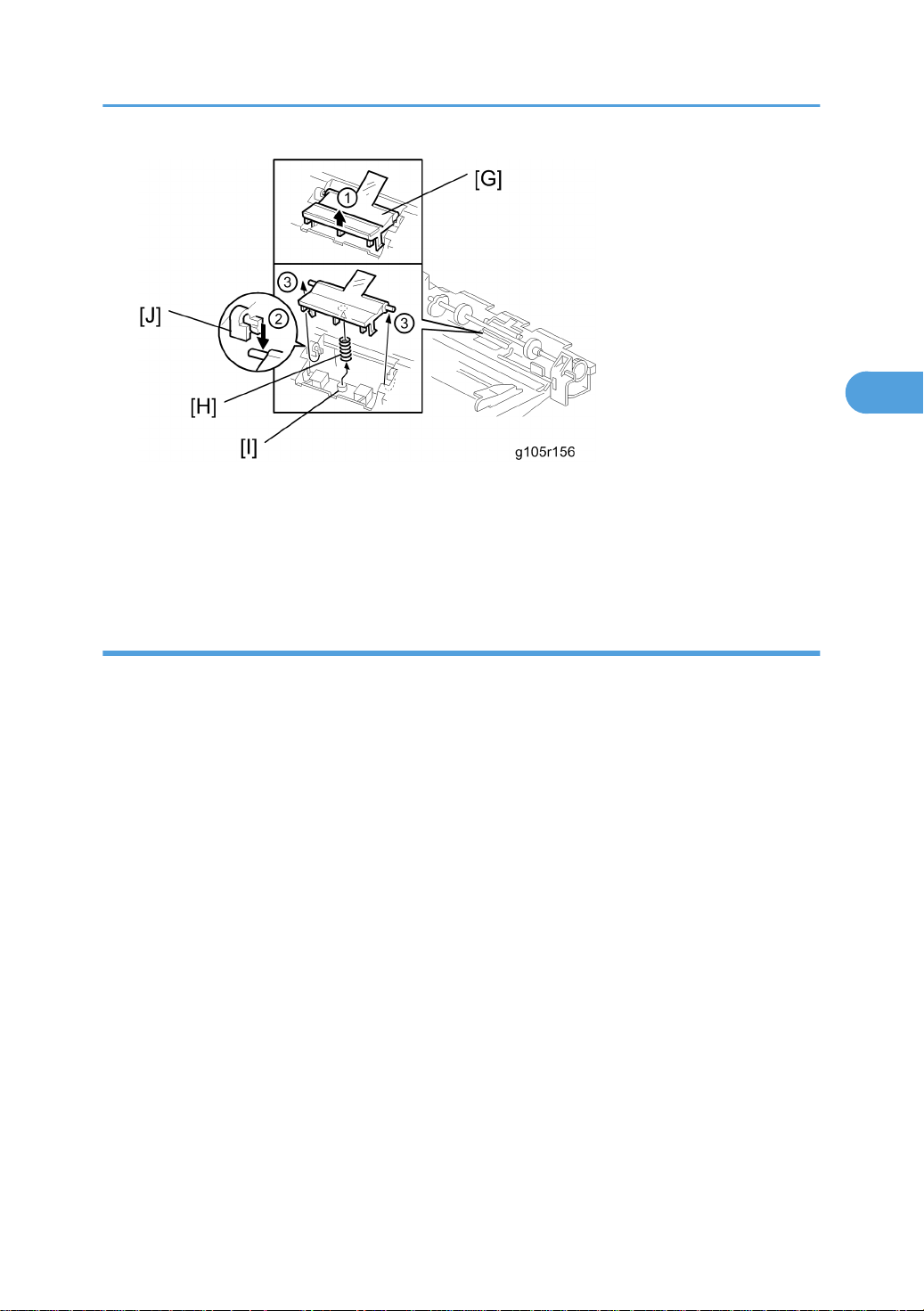
6. By-pass friction pad [G]
• Pull up the edge of the by-pass friction pad (¬).
• Pull the by-pass friction pad forward. When you do this, hold down the edge where its shaft is located
(Á).
Reassembling the by-pass friction pad
1. Place the spring [H] on the projection [I] of the by-pass tray.
2. Hold down the by-pass friction pad after you put the spring on the projection of pad’s reverse side
(®).
3. Release the by-pass tray friction pad when it passes through the bushing [J].
4. Pull up the shaft of the by-pass friction pad to the busing until it is clicked.
63
Page 65
3. Replacement and Adjustment
3
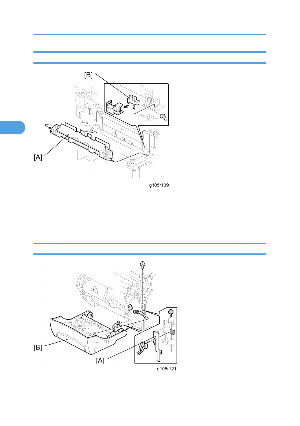
Registration Sensor
1. Front Door
2. Fusing unit (* Fusing unit)
3. Registration guide [A]
4. Registration sensor [B] ( x 1)
Paper Volume Sensor, End Sensor and Paper width Sensor
1. Standard tray (* Paper feed roller)
64
Page 66
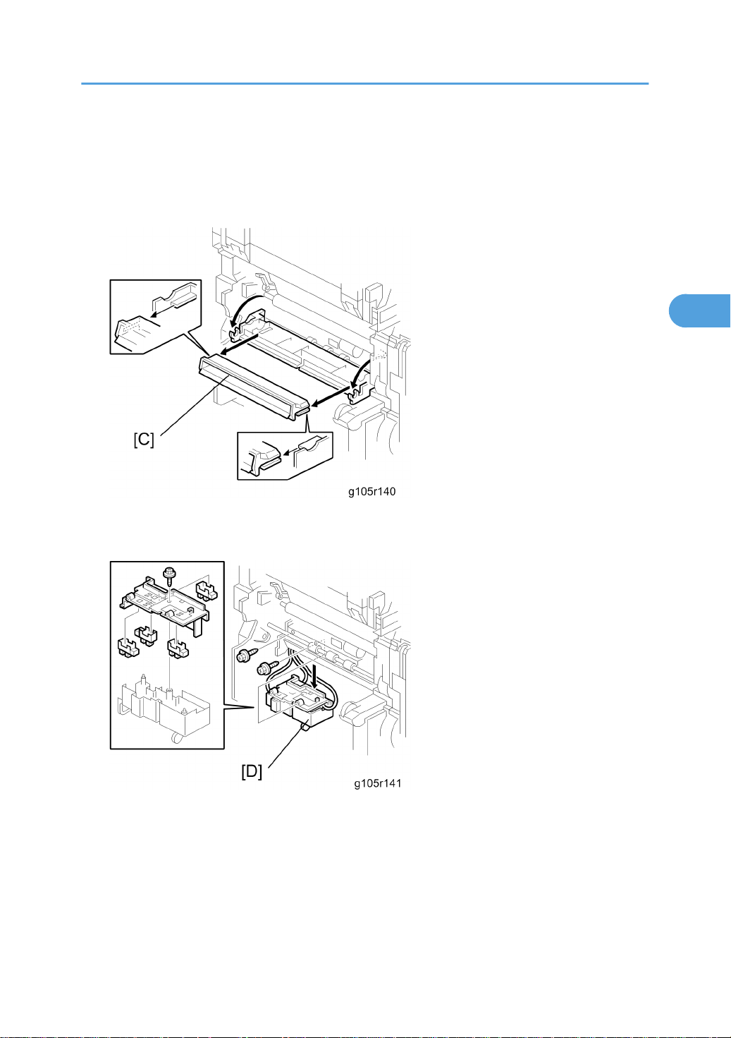
2. Front door
3
3. Fusing unit (* Fusing unit)
4. Harness cover [A] ( x 1)
5. Front door cover [B] ( x 1, x 2)
Paper Feed
6. Registration guide (* Registration sensor)
7. Paper dust case holder [C]
8. Tray paper sensor box [D] ( x 2)
65
Page 67
3. Replacement and Adjustment
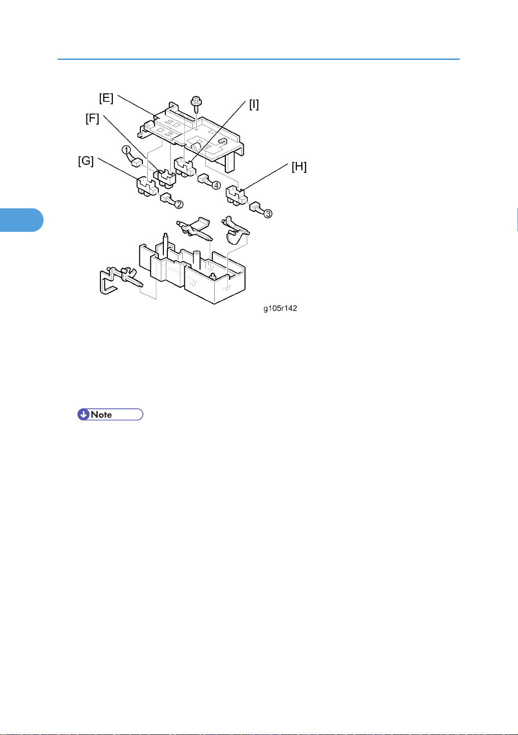
3
9. Tray paper sensor box cover [E] ( x 1,)
10. Paper height sensor [F] ( x 1)
11. Paper height sensor [G] ( x 1)
12. Paper end sensor [H] ( x 1)
13. Paper width sensor [I] ( x 1)
• Each sensor and each cable have a number written on them. Make sure to connect the correct
cables to each sensor.
66
Page 68
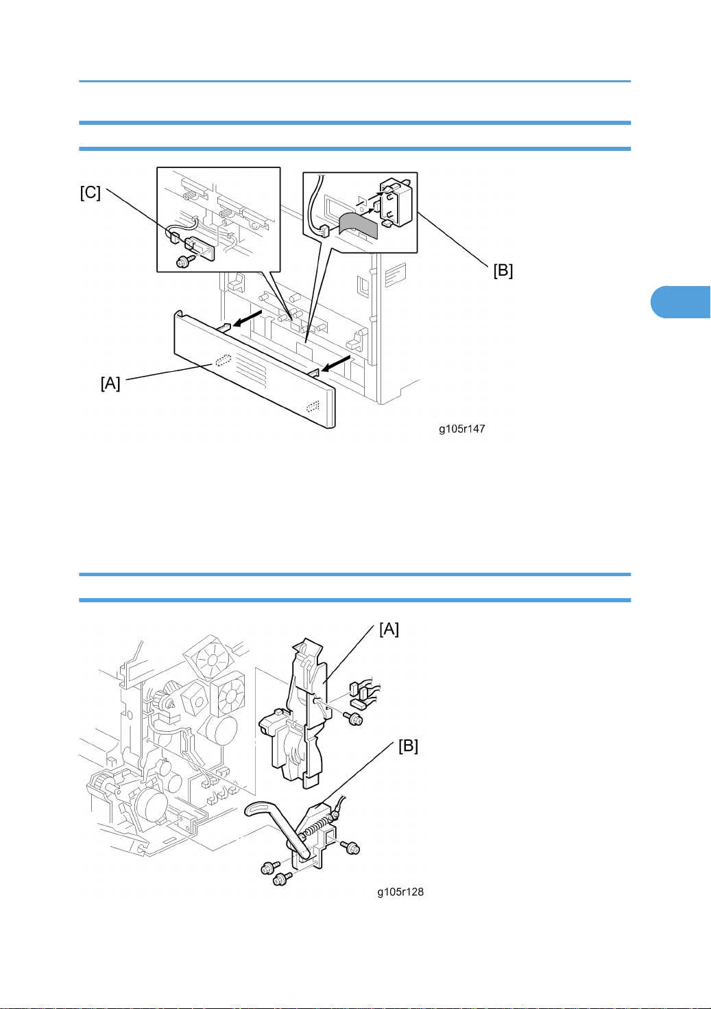
Paper Size Sensor and Temperature/ Humidity Sensor
3
1. Standard tray (* Paper feed roller)
Paper Feed
2. Rear cover [A]
3. Paper size sensor [B] ( x 1)
4. Temperature/Humidity sensor [C] ( x 1, x 1)
Paper Feed Motor
67
Page 69
3. Replacement and Adjustment
3
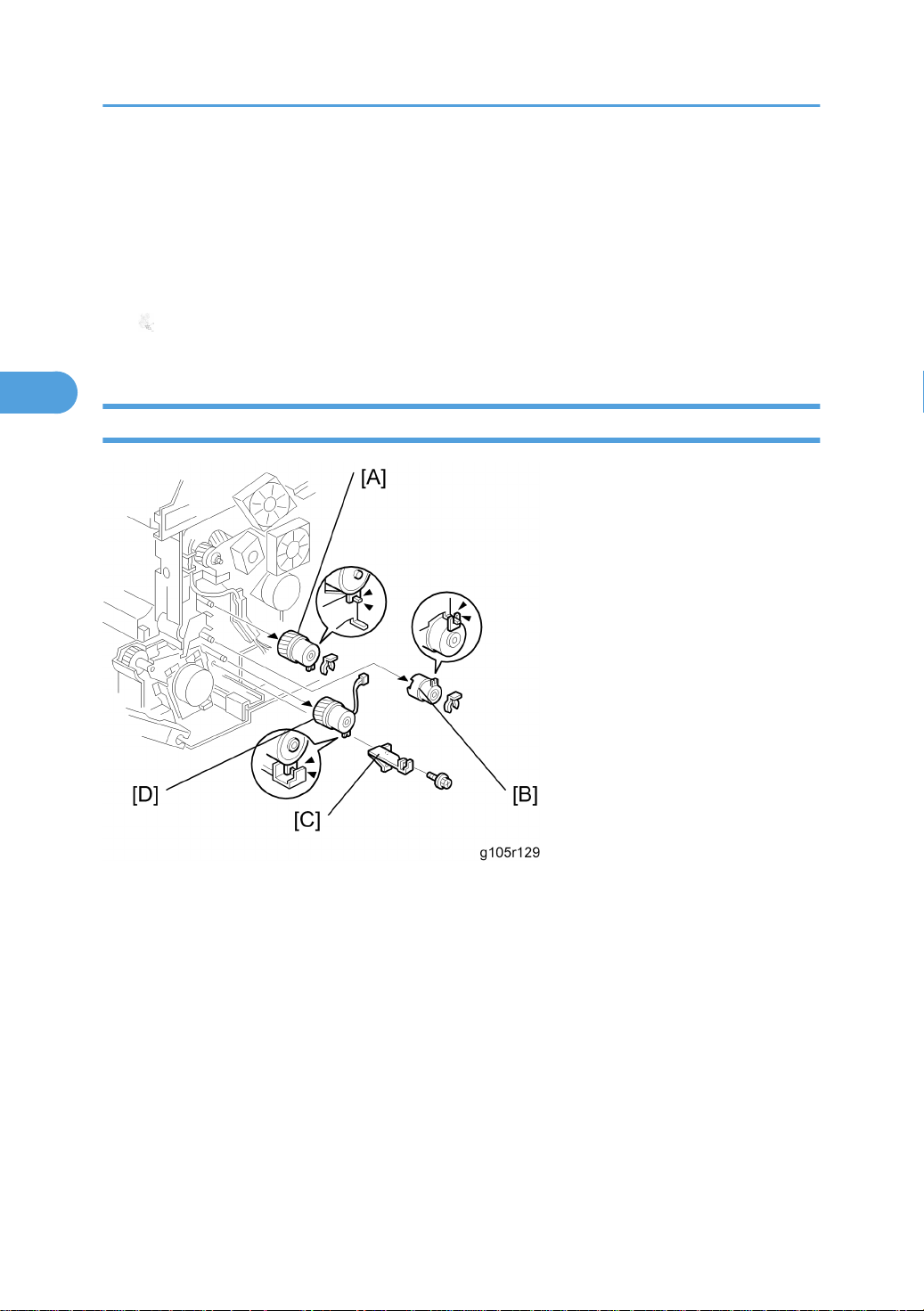
1. Front door cover (* Paper volume sensor, end sensor and paper width sensor)
2. Right cover ( x 1)
3. Side bar (* Electrical board unit)
4. Harness guide [A] ( x 1, x 3)
5. Front support unit [B] ( x 3)
6. Paper feed motor [C] ( x 4, x 1)
Paper Registration Clutch, Paper Feed Clutch and By-Pass Clutch
1. Front door
2. Front door cover (* Electrical board unit)
3. Right cover (* Electrical board unit)
4. Side bar (* Electrical board unit)
5. Harness cover (* Duplex motor and inverter motor)
6. Paper registration clutch [A] ( x 1, h x1)
7. By-pass clutch [B] ( x 1, x 1)
8. Front support unit (* Transfer roller contact motor)
9. Paper feed clutch support [C] ( x 1)
10. Paper feed clutch [D] ( x 1)
68
Page 70
Development
3
Development
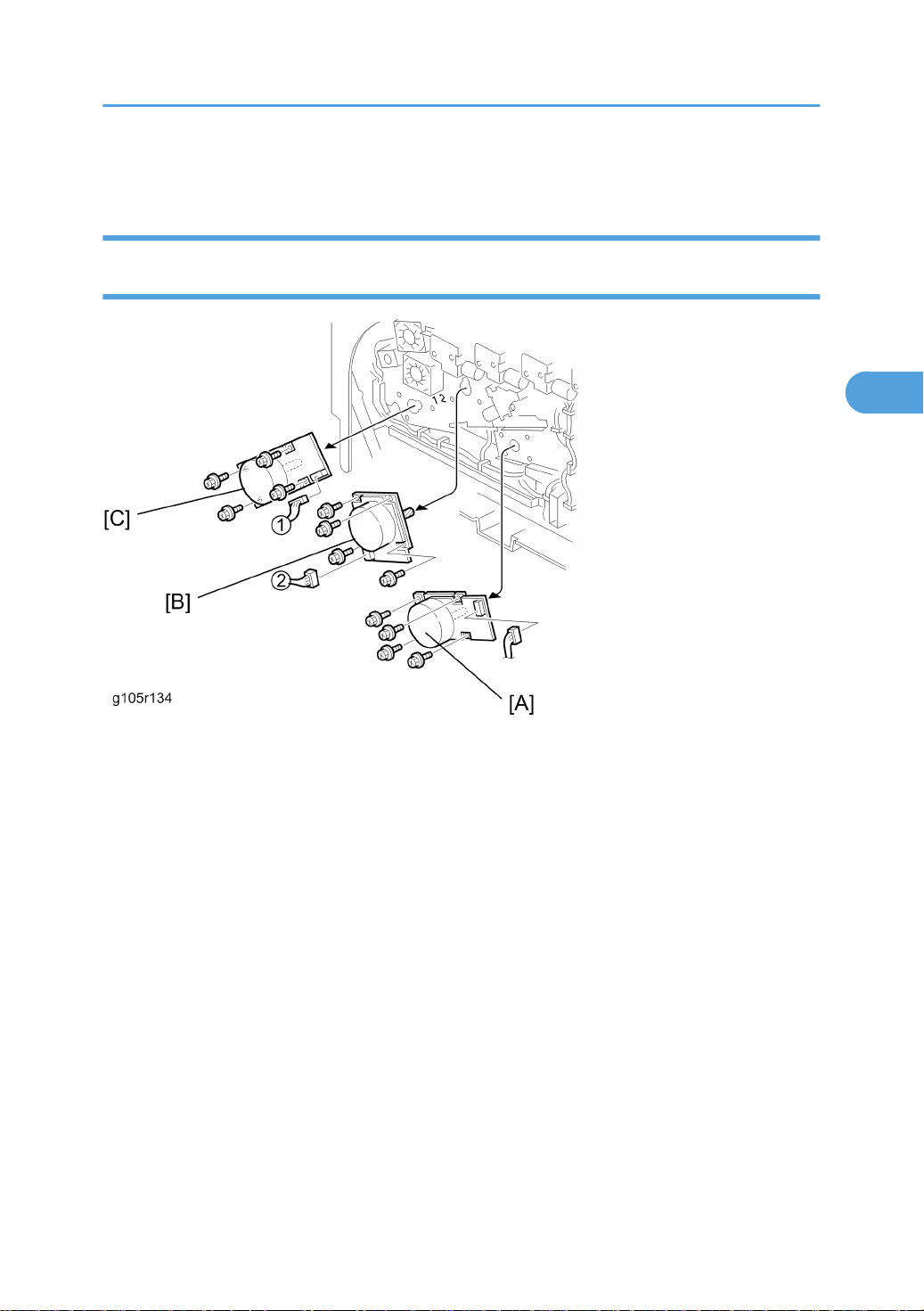
Color Development Motor, Color OPC Motor and Black OPC/Development Motor
1. Front door
2. Right cover (* Electrical board unit)
3. Color development motor [A] ( x 4, x 1)
4. Color OPC motor [B] ( x 4, x 1)
5. Black OPC/development motor [C] ( x 4, x 1)
69
Page 71
3. Replacement and Adjustment
3
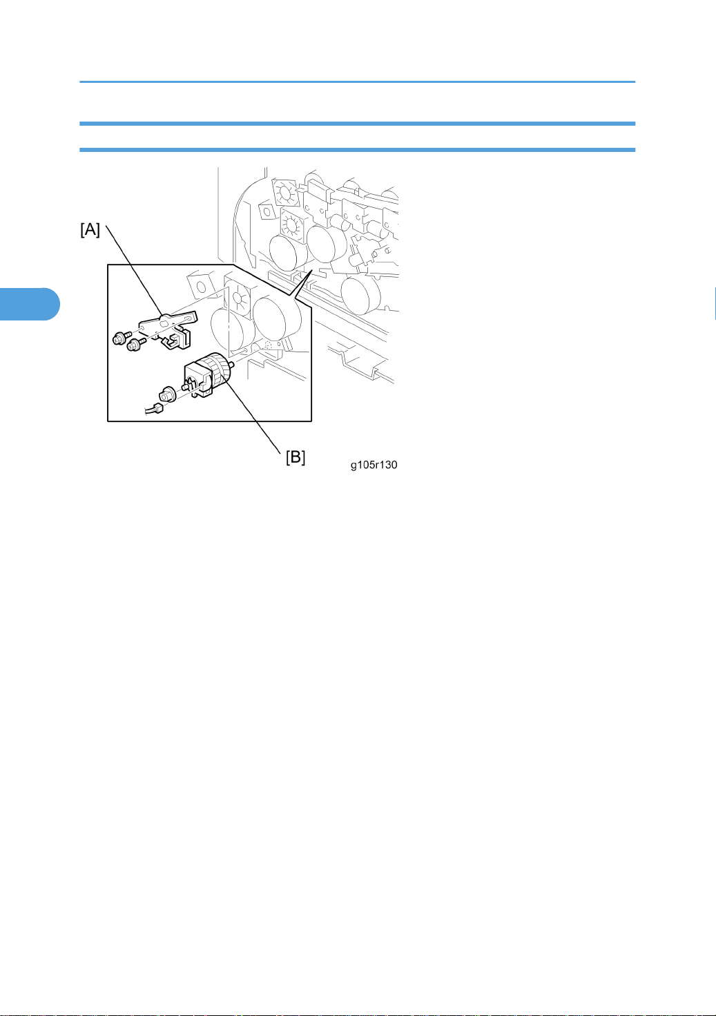
Development Clutch
1. Front door
2. Top cover
3. Right cover (* Electrical board unit)
4. Development clutch plate [A] ( x 2)
5. Development clutch [B] (metal pin x 1, x 1)
70
Page 72
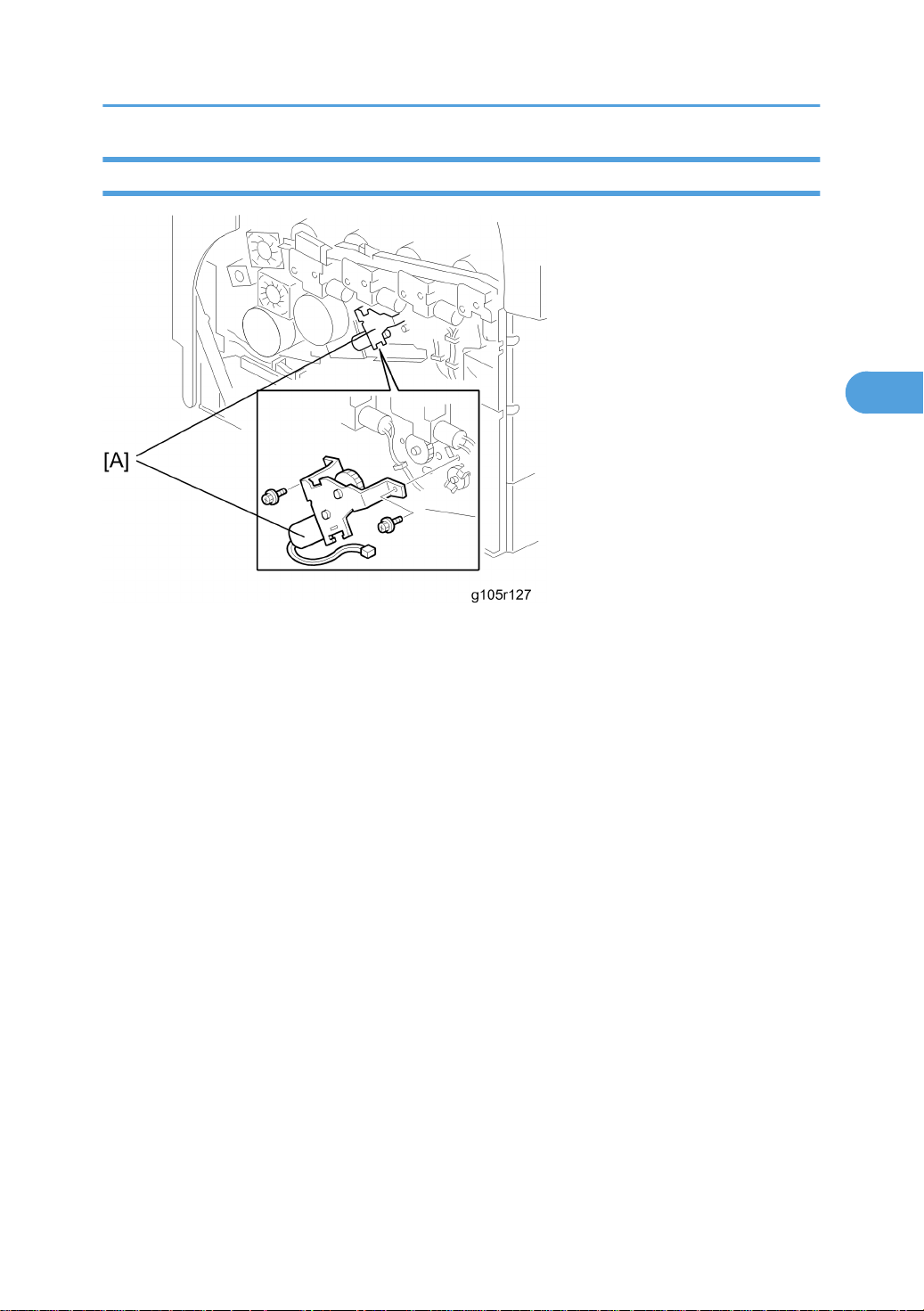
Transfer Belt Contact Motor
3
Development
1. Front door
2. Top cover
3. Right cover (* Electrical board unit)
4. Transfer belt contact motor unit [A] ( x 2, x 1)
71
Page 73
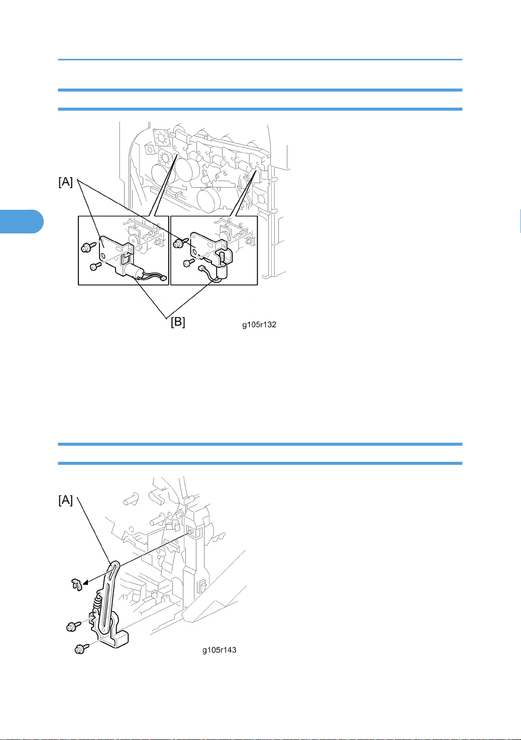
3. Replacement and Adjustment
3
Toner Supply Motor
1. Front cover
2. Top cover
3. Right cover (* Electrical board unit)
4. Toner supply motor unit [A] ( x 2, x 1)
5. Toner supply motor [B] ( x 2)
Transfer Roller Contact Motor
1. Front door
72
Page 74
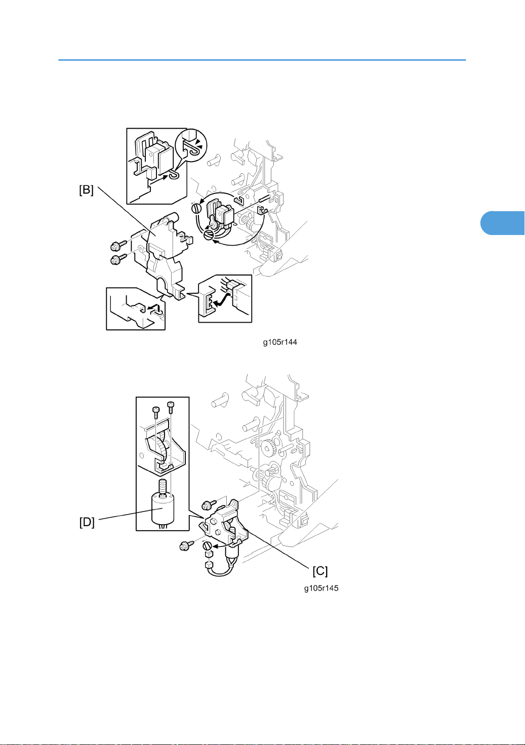
2. Left cover
3
3. Front door support unit [A] ( x 2, x 1)
Development
4. Inner cover [B] ( x 2)
5. Transfer roller contact motor unit [C] ( x 2, x 1)
6. Transfer roller contact motor [D] ( x 2)
73
Page 75
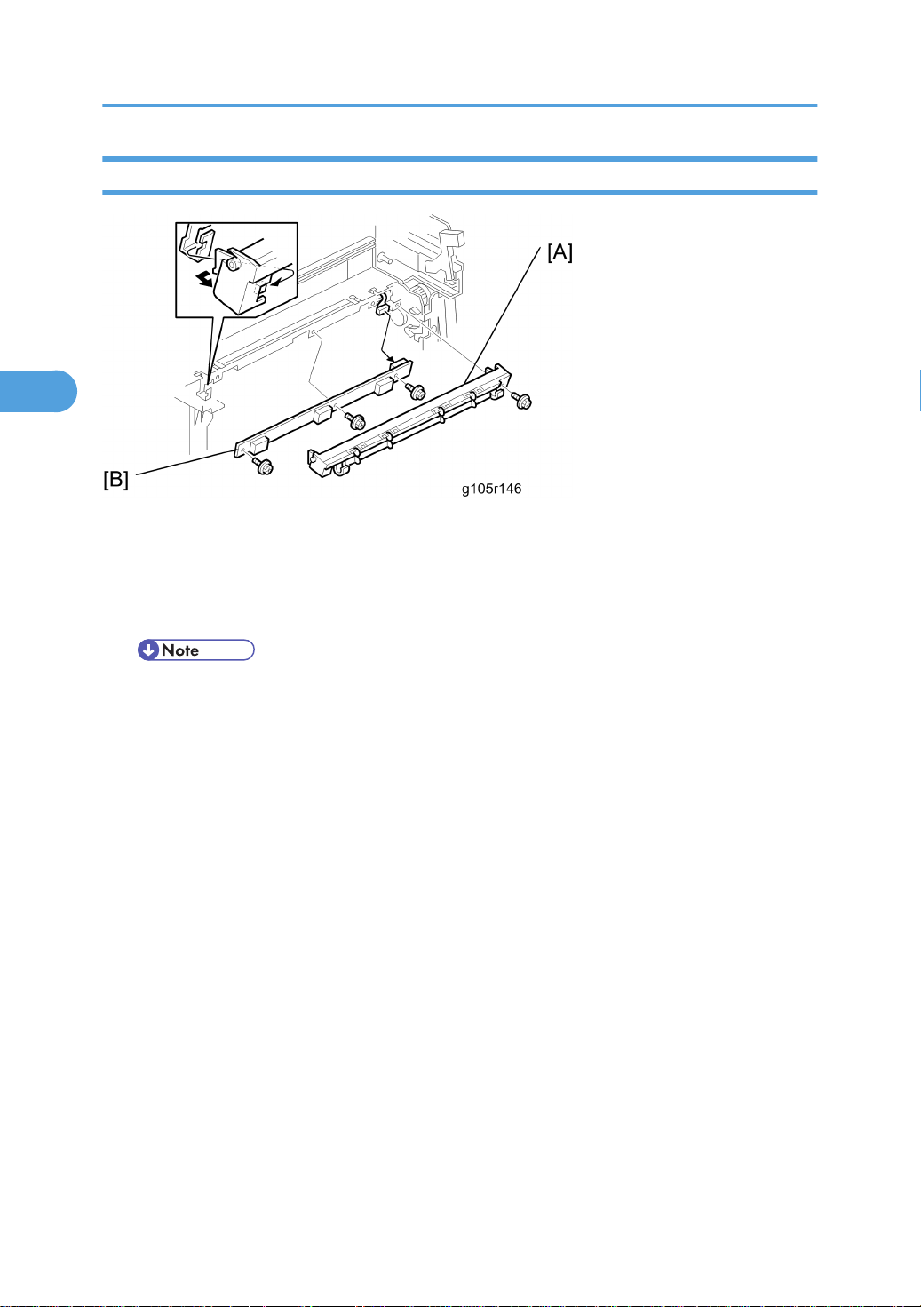
3. Replacement and Adjustment
3
ID Sensors
1. Front door
2. Fusing unit (* Fusing unit)
3. ID sensor cover [A] ( x 1)
4. ID sensor bracket [B] ( x 3, x 1)
• Do SP 2111 4 to adjust the ID sensors after you replace the ID sensor.
• Do SP 3148 1 to input the bar code number of the ID sensor board.
74
Page 76
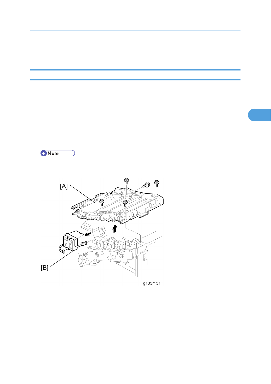
Drive
3
Drive unit
1. Top cover
2. Front door
3. Left cover
4. Transfer belt unit
5. PCU x 4
6. Toner bottle x 4
7. Toner supply motor unit x 4 (* Toner supply motor)
• Clean the toner hopper and toner transport path before you remove the toner supply motor unit.
If not, toner scattering can occur.
Drive
8. Right cover (* Electrical board unit)
9. Top frame [A] ( x 5)
10. Fusing unit fan [B] ( x 1)
75
Page 77
3. Replacement and Adjustment
3
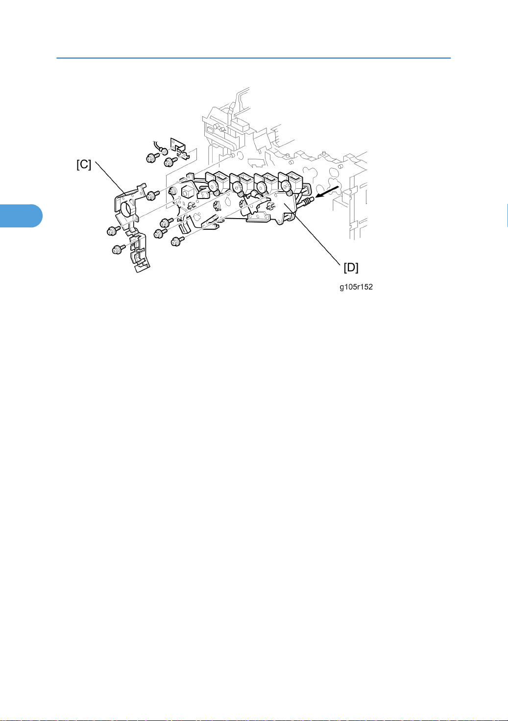
11. Harness guide [C] ( x 2)
12. Drive unit [D] ( x 6, x 16)
76
Page 78
Duplex
3
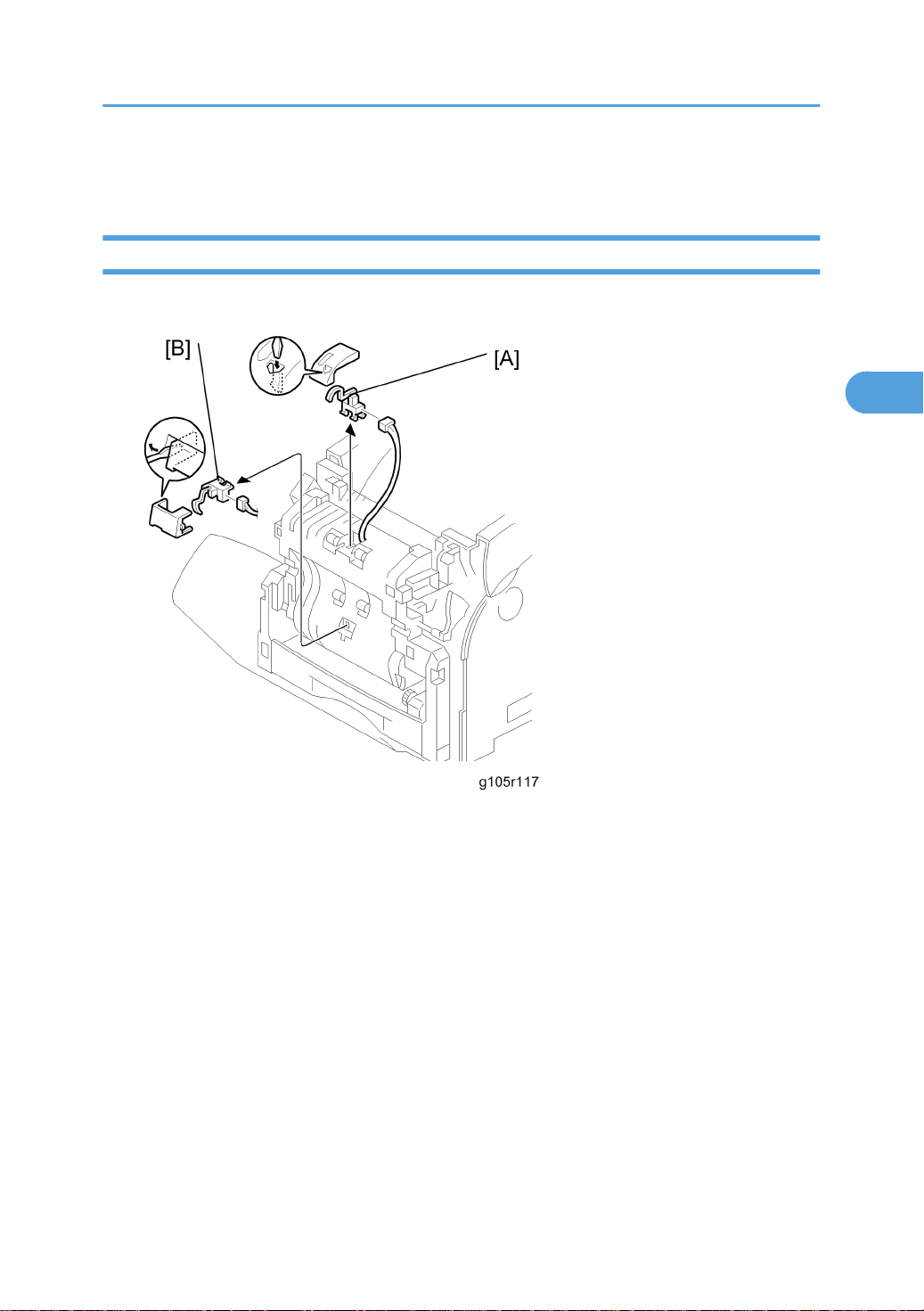
Duplex Jam Sensor
1. Front door cover (* Paper volume sensor, end sensor and paper width sensor)
Duplex
2. Duplex jam sensor 1 [A] ( x 1)
3. Duplex jam sensor 2 [B] ( x 1)
77
Page 79
3. Replacement and Adjustment
3
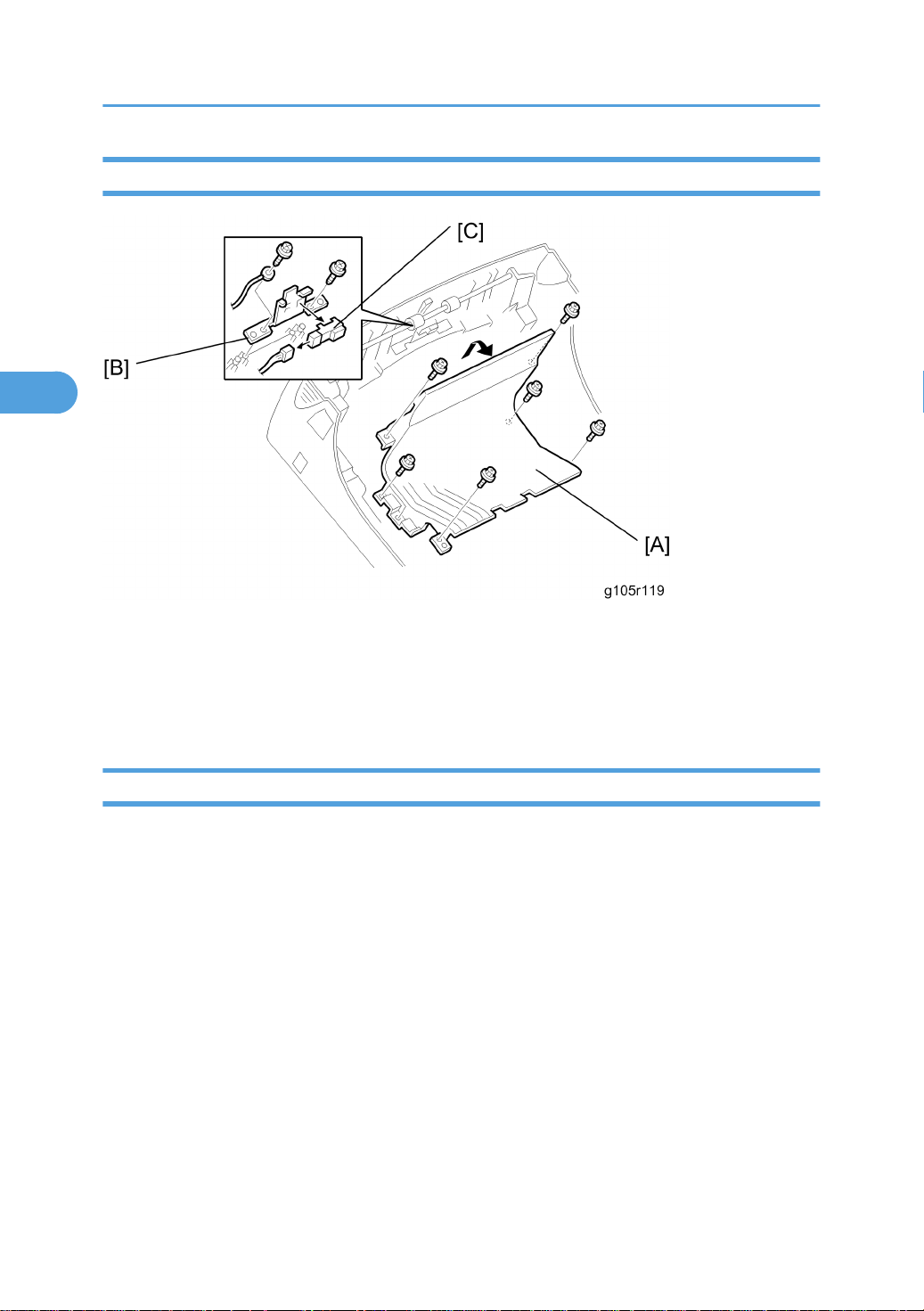
Inverter Sensor
1. Front door
2. Duplex paper guide plate [A] ( x 6)
3. Inverter sensor board [B]
4. Inverter sensor [C] ( x 1)
Duplex Motor and Inverter Motor
1. Front door
2. Front door cover (* Paper volume sensor, end sensor and paper width sensor)
78
Page 80
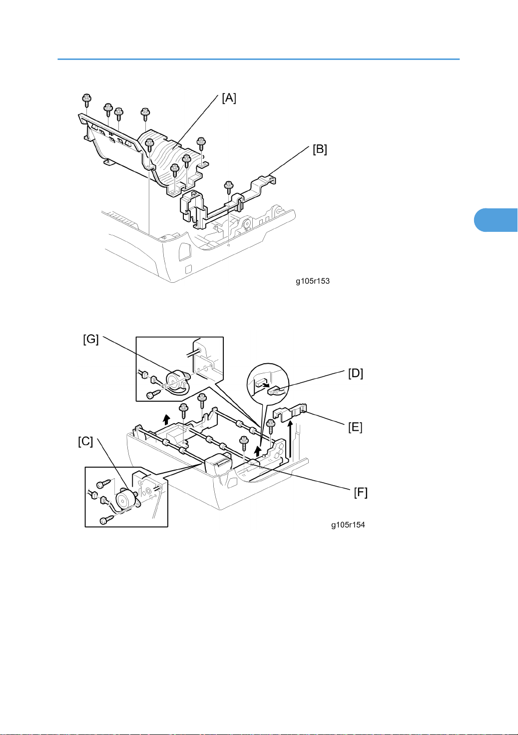
3. Duplex paper guide plate [A] ( x 6)
3
4. Harness cover [B] ( x 2)
Duplex
5. Inverter motor [C] ( x 2, x 1)
6. Harness [D]
7. Harness cover [E]
8. Duplex roller unit [F] ( x 4)
9. Duplex motor [G] ( x 2, x 1)
79
Page 81
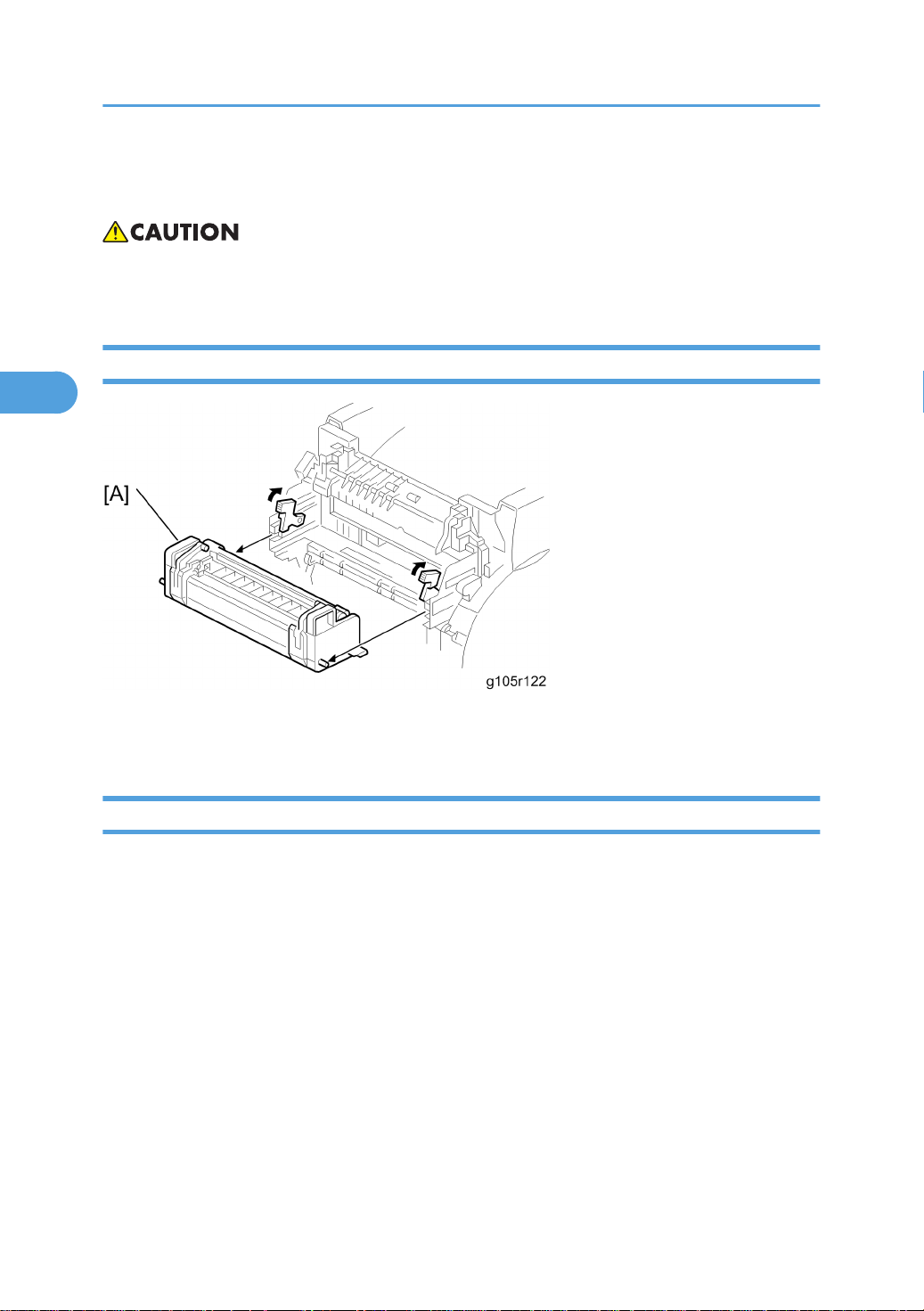
3. Replacement and Adjustment
3
Fusing
• Make sure that the fusing unit is cool before you touch it. The fusing unit can be very hot.
• Make sure to restore the insulators, shields, etc after you service the fusing unit.
Fusing Unit
1. Front door
2. Fusing unit [A]
Thermistor and Thermostat
1. Front door
2. Fusing unit (see above)
80
Page 82
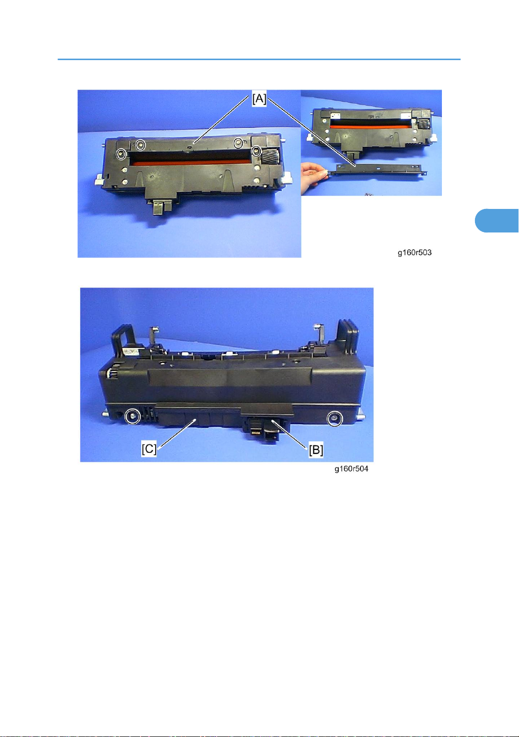
3. Fusing unit guide plate [A] ( x 4)
3
Fusing
4. Release the connector [B] from the fusing lower cover [C] (hook x 1).
5. Fusing lower cover [C] ( x 2)
81
Page 83
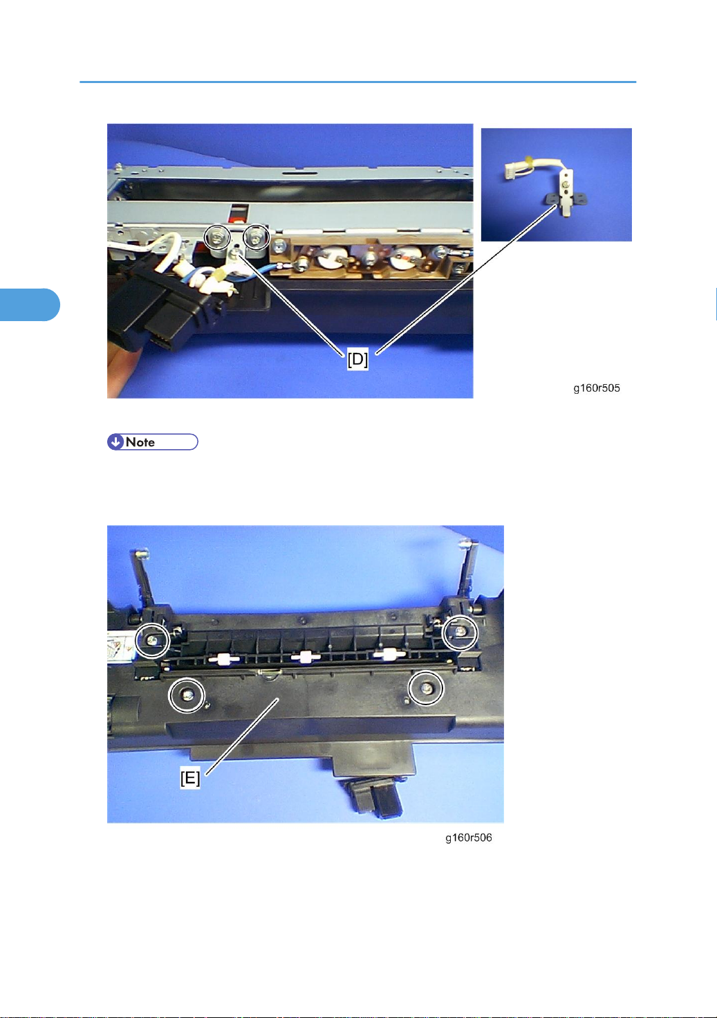
3. Replacement and Adjustment
3
6. Thermistor with bracket [D] ( x 2, x 1)
• Do not remove the thermistor from the bracket when removing it. The pressure of the thermistor
plate to the fusing belt is adjusted properly in the factory. If you remove it, some image problem
may occur.
7. Fusing upper cover [E] ( x 4)
82
Page 84
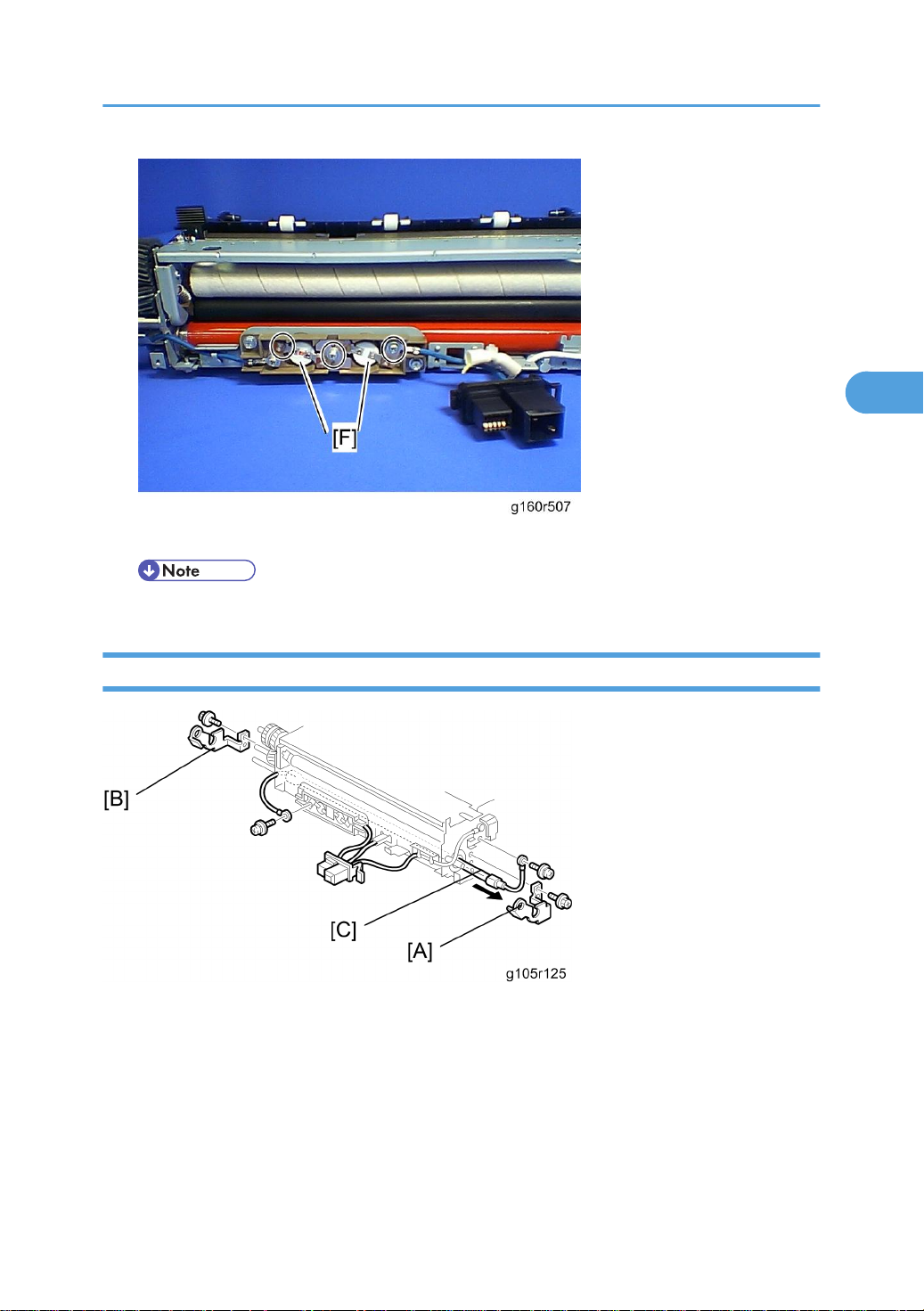
8. Thermostat [F] x 2 ( x 3)
3
• Do not recycle a thermostat that is already opened. Safety is not guaranteed if you do this.
Fusing
Fusing Lamp
1. Fusing unit
2. Fusing unit upper and lower cover (* Thermistor and thermostat)
3. Fusing supporter right and left plate (* Thermistor and thermostat)
4. Fusing lamp supporter right [A] ( x 1) and left plate [B] ( x 1)
5. Fusing lamp [C] ( x 2)
83
Page 85
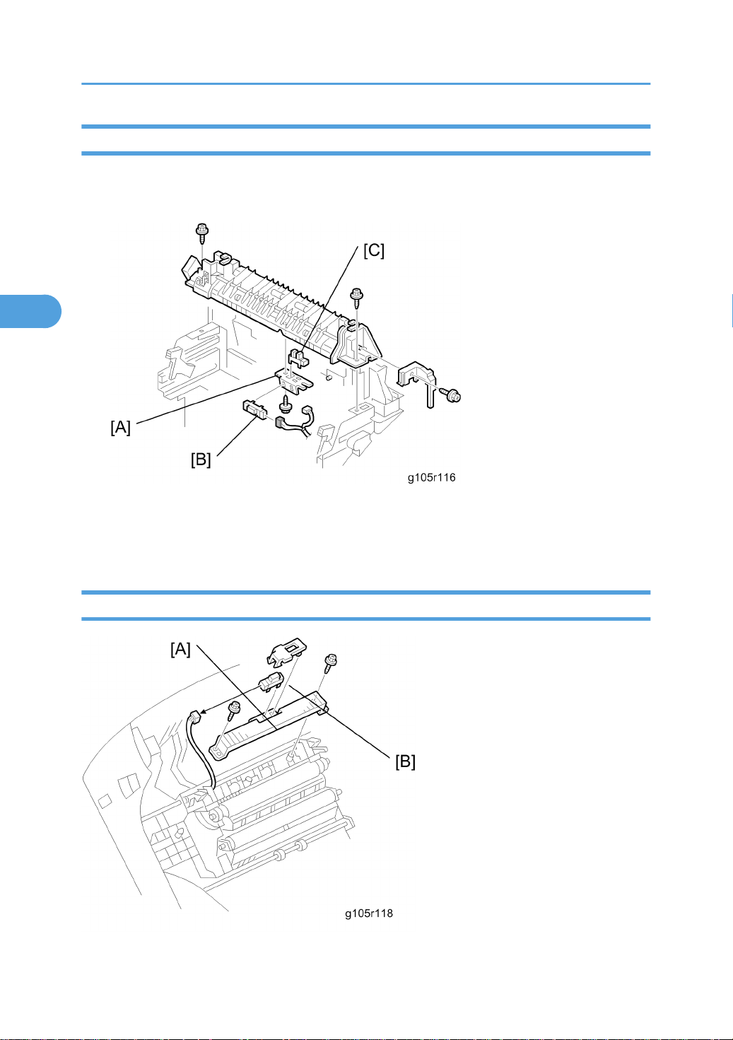
3. Replacement and Adjustment
3
Fusing Exit Sensor and Paper Exit Sensor
1. Front door
2. Paper exit unit ( x 3)
3. Sensor board [A] ( x 1, x 2)
4. Fusing exit senor [B]
5. Paper exit sensor [C]
Fusing Registration Sensor
84
Page 86
1. Front door
3
2. Paper guide [A] ( x 2, x 1)
3. Fusing registration sensor [B]
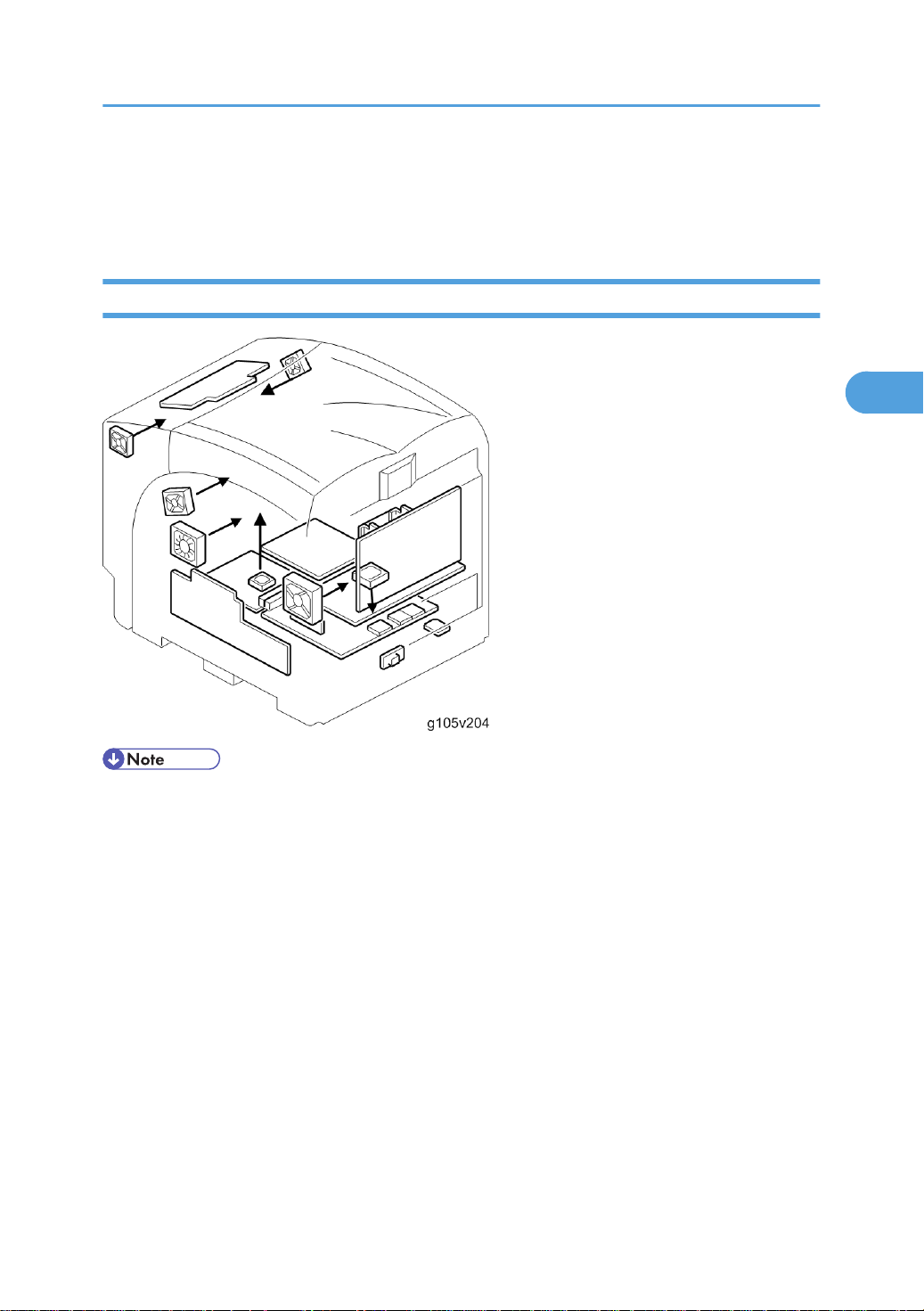
Fan Direction
Fusing
• You must reinstall the cooling fans in the original orientations. Do not reinstall the cooling fans opposite
to the original orientations, or the air will be blown in the wrong directions.
85
Page 87

3. Replacement and Adjustment
3
Adjustments
Gamma Adjustment
• Clean and/or replace related parts first to solve color quality problems. Do these procedures if
adjustments are necessary.
Summary
To adjust the printer gamma:
• Select the print mode you want to calibrate
• Print a color calibration test sheet
• Make the gradation scales on the printout smooth from the lowest to the highest density. Adjust the
CMY gradation scale at the top of the chart by balancing the density of the C, M, and Y gradation
scales - the CMY gray scale should change smoothly from minimum to maximum. There should be no
coloration.
Examine this color adjustment sheet:
86
Page 88
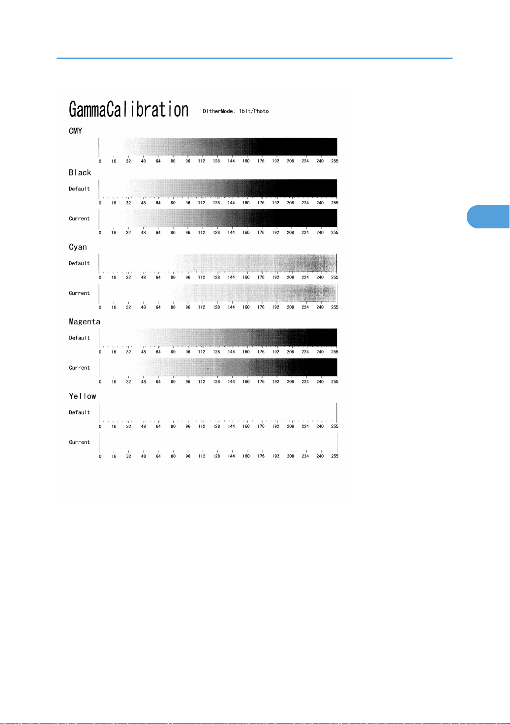
Adjustments
3
You can adjust 15 points for each color: (example [A]) between 0 (lowest density) [B] and 255 (highest
density) [C]. For each point, you can adjust the density within 0 and 255.
The gradation scales marked ‘Default’ are printed according to the default gamma settings in the flash
ROM in the controller. The gamma adjustment changes the densities at the adjustable points in the gradation
scale. The gradation scale marked “Current” shows the current settings.
Compare the “Current” gradation scale with the ‘Default’ at the time you do the adjustment procedure.
Select the density for each of the 15 adjustable points, excluding points 0 and 255, from the ‘Default’
gradation scale.
The NVRAM holds three sets of controller gamma settings:
• Those saved this time: Controller SP 1101 ToneCtlSet - Tone (Current)
87
Page 89

3. Replacement and Adjustment
3
• Those saved in the previous adjustment: Controller SP 1101 ToneCtlSet - Tone (Prev)
• The factory settings: Controller SP 1101 ToneCtlSet - Tone (Factory).
Adjustment Procedure
1. Enter the controller service mode.
2. Use the down arrow key to select Controller SP 1102 “ToneCtlSet”. Then press the Enter key.
3. Use the up/down key to select the mode you want to calibrate, Then press the Escape key until you
get back to the controller service mode menu.
4. Use the down arrow key to select Controller SP 1103 “PrnColorSheet”. Then press the Enter key.
5. Use the up/down key to select Controller SP 1103 001 “ToneCtlSheet” (normally this is displayed
by default). Then press the Enter key.
6. When “Execute?” shows, press the Enter key to print out the “color calibration test sheet”.
7. Press the Escape key 2 times to exit from the menu when “Execute OK” shows. (You return to Controller
SP 1103 “PrnColorSheet” in the controller service menu.)
8. Use the down arrow key to select Controller SP 1104 “ToneCtlValue”. Then press the enter key.
9. Use the up/down arrow key to select the setting you want to adjust. Then press the enter key. The
three digits in the display (example ‘016’) indicate a position on the color calibration test sheet.
Operation Panel Display Color Calibration Test Sheet
Set Black 1 Default Value 16
Set Black 2 Default Value 32
Set Black 3 Default Value 48
: :
: :
Set Black 13 Default Value 208
Set Black 14 Default Value 224
Set Black 15 Default Value 240
Set Cyan 1 to 15 See Set Black 1 to 15
Set Magenta 1 to 15 See Set Black 1 to 15
Set Yellow 1 to 15 See Set Black 1 to 15
Adjust the color density at each of the 15 points for each of the four colors.
88
Page 90

Adjustments
3
• Do these to decide what density value to input:
• Look at the color adjustment sheet.
• Look at the gradation scale entitled ‘Default’ for the color you want to adjust.
• Go along the scale until you reach the density you want to input.
• Read off the value on the scale and store it in the machine:
• Use the up/down key to move the cursor along the three-digit display. Then press the Enter key.
• Use the up/down key to change the digit at the cursor. Then press the Enter key.
• Press the Escape key to exit from the menu.
• Do the same for all 15 points.
10. When the density setting is complete for all colors, print out a color adjustment sheet again and make
sure that the gradation scale for each printed color is smooth and that the CMY gradation scale is
gray. Do the adjustment again if there is an anomaly (normally, repeat this procedure 3 to 5 times).
11. Do these when the adjustment results are satisfactory:
• Use Controller SP 1105 “ToneCtlSave” in the controller service menu, to store the new settings
in the controller.
• Reset the controller (press the [Reset] key when the machine is off line”) to use the new settings.
• You must reset the controller to keep the new settings in the controller NVRAM.
89
Page 91

3. Replacement and Adjustment
3
90
Page 92

4. Troubleshooting
4
Process Control Results
The table below lists the process control results shown in SP 3821.
Number Result Notes
10 Success No error
21 ID sensor correction error SC 400
22 ID sensor: LED adjustment error SC 418
31 Charge bias correction error SC 300 to 307
51 High Vmin (Bk), High K2 (Color) error
52 Low K2 (Color) error
53 High K5 error
54 Low K5 error
55 High development gamma
56 Low development gamma
57 Development bias adjustment error
58 Development bias adjustment error
90 No process control -
SP 3145 (see the note below the
table)
SP 3146 (see the note below the
table)
SP 3147 (see the note below the
table)
SP 3147 (see the note below the
table)
Gamma > 5.0 (see the note
below the table)
Gamma < 0.5 (see the note
below the table)
Vk >150V (see the note below
the table)
Vk < -150V (see the note below
the table)
99 Not successful
Interrupt during the process
control (e.g. Door open)
91
Page 93

4. Troubleshooting
4
• This error code does not usually occur. If no problem is observed with image density and/or
development gamma, nothing needs to be done. If an image problem such as low image density is
observed, check the following points: Transfer belt/PCU/ID sensor/Toner bottle
The 8 numbers on the LCD in SP 3821 indicate the process control result for each color.
There are two numbers for each color. The numbers are shown from left to right on the display as follows:
Black, Magenta, Cyan, Yellow. For example, if process control for each color is successful: 10 (Black),
10 (Magenta), 10 (Cyan), 10 (Yellow)
92
Page 94

Service Call Conditions
4
Service Call Conditions
Summary
1. All SCs are logged.
2. First disconnect then reconnect the connectors before you replace the PCBs if the problem concerns
electrical circuit boards.
3. First check the mechanical load before you replace motors or sensors if the problem concerns a motor
lock.
There are 4 levels of service call conditions.
Level Definition Reset Procedure
To prevent damage to the machine, the main
A
B
C
D
machine cannot be operated until a service
representative has reset the SC.
SCs that disable only the features that use the
defective item. Although these SCs are not shown to
the user under normal conditions, they are displayed
on the operation panel only when the defective
feature is selected.
The SC history is updated. The machine can be
operated as usual.
Turning the main switch off then on resets SCs
displayed on the operation panel. These are
redisplayed if the error occurs again.
Do SP 5810, and then turn the
main power switch off and on.
Turn the operation switch or main
switch off and on.
The SC will not be displayed.
Only the SC history is updated.
Turn the operation switch off and
on.
SC Code Descriptions
• Remove the NVRAM from the old board and install it on the new one when you replace the EGB or
the controller board.
• The SC level is indicated under SC number in the list below.
• The numbers (1, etc.) in the “Possible Cause/Requirement Action” column indicate the required
actions.
93
Page 95

4. Troubleshooting
4
Engine SC
SC
[Level]
195
[D]
202
[D]
203
[C]
Symptom Possible Cause/Required Action
Incorrect serial number
When checking the registered
product number, it does not
match the printer’s product
number.
Polygon motor error: Time out with the polygon motor activated
After the polygon motor turns
on or changes the speed,
SCRDY_N is not active within
10 seconds.
Polygon motor error: Time out with the polygon motor inactivated
After the polygon motor turns
off or changes the speed,
SCRDY_N is not inactive
within 10 seconds.
• Registered product number does not match the
printer’s product number.
1. Ask your service key man.
• Disconnected cable from the polygon motor drive
board or defective connection
• Defective polygon motor or drive board
• Disconnected cable from the polygon motor drive
board or defective connection
• Defective polygon motor or drive board
94
204
[C]
205
[D]
Polygon motor error: XSCRDY signal error
• Disconnected cable from the polygon motor drive
PMRDY_N signal
consecutively detects that the
polygon motor is an inactive
state while LDB unit scans.
Polygon motor error: XSCRDY signal not stable
PMRDY_N signal
consecutively detects that the
polygon motor is an inactive
state while the polygon motor
turns on or changes the speed.
board or defective connection
• Defective polygon motor or drive board
1. Check the connectors.
2. Replace the polygon motor.
3. Replace the polygon motor drive board.
• Disconnected cable from the polygon motor drive
board or defective connection
• Defective polygon motor or drive board.
1. Check the connectors.
2. Replace the polygon motor.
3. Replace the polygon motor drive board.
Page 96

Service Call Conditions
4
SC
[Level]
210
[C]
211
[C]
Symptom Possible Cause/Required Action
Trailing edge laser detection error: [K]
• Disconnected cable from the laser synchronizing
The laser synchronizing
detection signal for LDB [K] of
the trailing edge is not
detected for one second after
the LDB unit turned on when
detecting the main scan
magnification.
Trailing edge laser detection error: [Y]
The laser synchronizing
detection signal for LDB [Y] of
the trailing edge is not
detected for one second after
the LDB unit turned on when
detecting the main scan
magnification.
• Defective laser synchronizing detector
• Defective LDB
• Defective EGB
1. Check the connectors.
2. Replace the laser-synchronizing detector.
3. Replace the LDB.
4. Replace the EGB.
Same as SC 210
detection unit or defective connection
212
[C]
213
[C]
Trailing edge laser detection error: [M]
The laser synchronizing
detection signal for LDB [M] of
the trailing edge is not
detected for one second after
the LDB unit turned on when
detecting the main scan
magnification.
Trailing edge laser detection error: [C]
The laser synchronizing
detection signal for LDB [C] of
the trailing edge is not
detected for one second after
the LDB unit turned on when
Same as SC 210
Same as SC 210
95
Page 97

4. Troubleshooting
4
SC
[Level]
220
[D]
222
[D]
Symptom Possible Cause/Required Action
detecting the main scan
magnification.
Laser Synchronizing Detection Error: LDB of the leading edge [K]
• Disconnected cable from the laser synchronizing
detection unit or defective connection
The laser synchronizing
detection signal for LDB [K] of
the leading edge is not output
for two seconds after LDB unit
turns on while the polygon
motor is rotating normally.
Leading edge laser detection error: [Y]
The laser synchronizing
detection signal for LDB [Y] of
the leading edge is not output
for two seconds after LDB unit
turns on while the polygon
motor is rotating normally.
• Defective laser synchronizing detector
• Defective LDB
• Defective EGB
1. Check the connectors.
2. Replace the laser-synchronizing detector.
3. Replace the LDB.
4. Replace the EGB.
Same as SC 220
96
224
[D]
226
[D]
Leading edge laser detection error: [M]
The laser synchronizing
detection signal for LDB [M] of
the leading edge is not output
for two seconds after LDB unit
turns on while the polygon
motor is rotating normally.
Leading edge laser detection error: [C]
The laser synchronizing
detection signal for LDB [C] of
the leading edge is not output
for two seconds after LDB unit
Same as SC 220
Same as SC 220
Page 98

Service Call Conditions
4
SC
[Level]
230
[C]
231
[C]
Symptom Possible Cause/Required Action
turns on while the polygon
motor is rotating normally.
FGATE: On error [K]
The PFGATE ON signal does
not assert within 5 seconds
after processing the image in
normal job or MUSIC for [K]
starts.
FGATE: Off error [K]
• The PFGATE ON signal
still asserts within 5
seconds after processing
the image in normal job
or MUSIC for [K] ends.
• The PFGATE ON signal
still asserts when the next
job starts.
• Defective connection between the controller board
and EGB
• Defective cable between the EGB and LDB
1. Check the connectors.
2. Replace the LDB.
3. Replace the EGB.
• Defective connection between the controller board
and EGB
• Defective cable between the EGB and LDB
1. Check the connectors.
2. Replace the LDB.
3. Replace the EGB.
232
[C]
233
[C]
FGATE: On error [Y]
The PFGATE register of GAVD
does not assert within 5
seconds after processing the
image in normal job or MUSIC
for [Y] started.
FGATE: Off error [Y]
• The PFGATE ON signal
still asserts within 5
seconds after processing
the image in normal job
or MUSIC for [K] ends.
• The PFGATE ON signal
still asserts when the next
job starts.
Same as SC 230
Same as SC 231
97
Page 99

4. Troubleshooting
4
SC
[Level]
234
[C]
235
[C]
Symptom Possible Cause/Required Action
FGATE: On error [M]
The PFGATE register of GAVD
does not assert within 5
seconds after processing the
image in normal job or MUSIC
for [M] started.
FGATE: Off error [M]
• The PFGATE ON signal
still asserts within 5
seconds after processing
the image in normal job
or MUSIC for [M] ends.
• The PFGATE ON signal
still asserts when the next
job starts.
FGATE: On error [C]
Same as SC 230
Same as SC 231
236
[C]
237
[C]
240
[D]
The PFGATE register of GAVD
does not assert within 5
seconds after processing the
image in normal job or MUSIC
for [C] started.
FGATE: Off error [C]
• The PFGATE ON signal
still asserts within 5
seconds after processing
the image in normal job
or MUSIC for [C] ends.
• The PFGATE ON signal
still asserts when the next
job starts.
LDB error [K]
The EGB detects LDB error a
few times consecutively when
Same as SC 230
Same as SC 231
• Defective LDB
1. Replace the LDB.
98
Page 100

Service Call Conditions
4
SC
[Level]
241
[D]
242
[D]
243
[D]
Symptom Possible Cause/Required Action
LDB unit turns on after LDB
initialization.
LDB error [Y]
The EGB detects LDB error a
few times consecutively when
LDB unit turns on after LDB
initialization.
LDB error [M]
The EGB detects LDB error a
few times consecutively when
LDB unit turns on after LDB
initialization.
LDB error [C]
The EGB detects LDB error a
few times consecutively when
LDB unit turns on after LDB
initialization.
Same as SC240
Same as SC240
Same as SC240
270
[D]
300
[D]
LDU shutter error
Sensor output does not
change even if 1 second
passes after the LDU shutter
motor is on.
High voltage power board: Charge voltage output error [K]
The measured voltage is not
proper when EGB measures
the charge output for each
color.
• Sensor defective or LDU shutter motor defective
1. Replace the LDU shutter sensor or shutter motor.
• Defective charge roller
• Defective connectors
• Disconnected harness
• Defective high voltage power 1
1. Check the connectors.
2. Replace the PCU for black.
3. Replace the drum positioning plate.
4. Replace the high voltage power 1.
99
 Loading...