

Ricoh J-CF, G307 Service Manual

Model J-CF FAX UNIT
(Machine Code: G307)
SERVICE MANUAL
December 21st, 2001
Subject to change

i
TABLE OF CONTENTS
INSTALLATION ............................................................................... 1-1
1.1 FAX UNIT.................................................................................................. 1-1
1.1.1 CAUTIONS.......................................................................................1-1
1.1.2 FAX OPTION INSTALLATION.........................................................1-2
1.1.3 INSTALLING THE HANDSET ..........................................................1-4
1.2 FAX UNIT OPTIONS.................................................................................1-5
1.2.1 G3 INTERFACE UNIT INSTALLATION............................................1-5
1.2.2 ISDN OPTION INSTALLATION........................................................1-7
1.2.3 FAX FUNCTION UPGRADE UNIT INSTALLATION.........................1-9
1.2.4 EXPANSION MEMORY INSTALLATION.......................................1-10
2. TROUBLESHOOTIN G................................................................ 2-1
2.1 ERROR CODES ........................................................................................2-1
2.2 ERROR CODES FOR THE ISDN OPTION...............................................2-9
2.2.1 D-CHANNEL LAYER MANAGEMENT...........................................2-10
2.2.2 D-CHANNEL, LAYER 1..................................................................2-10
2.2.3 D-CHANNEL LINK LAYER.............................................................2-10
2.2.4 D-CHANNEL NETWORK LAYER...................................................2-11
2.2.5 B-CHANNEL LINK LAYER.............................................................2-11
2.2.6 B-CHANNEL NETWORK LAYER...................................................2-12
2.2.7 TRANSPORT LAYER.....................................................................2-12
2.2.8 SESSION LAYER...........................................................................2-13
2.2.9 DOCUMENT LAYER......................................................................2-14
2.2.10 PRESENTATION LAYER.............................................................2-14
2.3 FAX SC CODES......................................................................................2-15
2.3.1 OVERVIEW....................................................................................2-15
2.3.2 SC1201...........................................................................................2-15
2.3.3 SC1207...........................................................................................2-15
2.3.4 FAX SC CODE TABLE...................................................................2-16
2.4 ISDN TEST FUNCTION ..........................................................................2-17
2.4.1 LEDS..............................................................................................2-17
2.4.2 BACK-TO-BACK TEST...................................................................2-18
3. SERVICE TABLES...................................................................... 3-1
3.1 SERVICE PROGRAM MODE....................................................................3-1
3.1.1 SERVICE PROGRAM MODE OPERATION.....................................3-1
Entering and Exiting SP mode..............................................................3-1
SP Mode Button Summary...................................................................3-2
Switching Between SP Mode and Copy Mode for Test Printing ...........3-3
Selecting the Program Number.............................................................3-3
3.1.2 SERVICE PROGRAM MODE TABLES............................................3-4
3.2 BIT SWITCHES.........................................................................................3-9
3.2.1 SYSTEM SWITCHES.......................................................................3-9
3.2.2 SCANNER SWITCHES..................................................................3-22
3.2.3 PRINTER SWITCHES....................................................................3-26

ii
3.2.4 COMMUNICATION SWITCHES.....................................................3-31
3.2.5 G3 SWITCHES...............................................................................3-40
3.2.6 G3-2 SWITCHES............................................................................3-47
3.2.7 G4 INTERNAL SWITCHES............................................................3-53
3.2.8 G4 PARAMETER SWITCHES ........................................................3-60
3.3 NCU PARAMETERS...............................................................................3-63
3.4 DEDICATED TRANSMISSION PARAMETERS......................................3-74
3.4.1 PROGRAMMING PROCEDURE....................................................3-74
3.4.2 PARAMETERS...............................................................................3-75
3.5 SERVICE RAM ADDRESSES.................................................................3-79
4. DETAILED SECTION DESCRIPTIONS ...................................... 4-1
4.1 OVERVIEW...............................................................................................4-1
4.2 BOARDS...................................................................................................4-2
4.2.1 FCU..................................................................................................4-2
4.2.2 MBU..................................................................................................4-3
4.2.3 NCU (US) .........................................................................................4-4
4.2.4 NCU (EUROPE/ASIA)......................................................................4-5
4.2.5 SG3 BOARD.....................................................................................4-6
4.2.6 SIG4 BOARD....................................................................................4-7
4.3 VIDEO DATA PATH..................................................................................4-8
4.3.1 TRANSMISSION..............................................................................4-8
Memory Transmission and Parallel Memory Transmission...................4-9
Immediate Transmission.......................................................................4-9
JBIG Transmission ...............................................................................4-9
I-G3 (ISDN G3) Transmission...............................................................4-9
Adjustments..........................................................................................4-9
4.3.2 RECEPTION...................................................................................4-10
4.4 FAX COMMUNICATION FEATURES .....................................................4-12
4.4.1 PERSONAL/INFORMATION/TRANSFER BOXES.........................4-12
Personal Box (Confidential Box).........................................................4-12
Transfer Box.......................................................................................4-13
Information Box (Polling Tx)................................................................4-14
4.4.2 MULTI-PORT COMMUNICATION..................................................4-15
4.4.3 DOCUMENT SERVER...................................................................4-16
4.4.4 LAN FAX DRIVER..........................................................................4-17
Regular transmission.......................................................................... 4-18
Print and transmission........................................................................4-18
Using Document Server......................................................................4-18
SPECIFICATIONS.....................................................................SPEC-1
1. GENERAL SPECIFICATIONS.............................................................SPEC-1
2. CAPABILITIES OF PROGRAMMABLE ITEMS...................................SPEC-3
3. MACHINE CONFIGURATION.............................................................SPEC-4

21 December, 2001 FAX UNIT
1-1
Installation
1. INSTALLATION
1.1 FAX UNIT
1.1.1 CAUTIONS
NOTE: 1) Never install telephone wiring during a lightning storm.
2) Never install telephone jacks in wet locations unless the jack is
specifically designed for wet locations.
3) Never touch uninsulated telephone wires or terminals unless the
telephone line has been disconnected at the network interface.
4) Use caution when installing or modifying telephone lines.
5) Avoid using a telephone (other than a cordless type) during an electrical
storm. There may be a remote risk of electric shock from lightning.
6) If there is a gas leak, do not use the telephone in the vicinity of the leak
to report it.
!
CAUTION
1. Before installing the fax unit, switch off the main power and operation
switches, and disconnect the power cord.
2. The fax unit contains a lithium battery. The danger of explosion exists if
a battery of this type is incorrectly replaced. Replace only with the same
or an equivalent type recommended by the manufacturer. Discard used
batteries in accordance with the manufacturer’s instructions.
Note for Australia:
Unit shall be connected to Telecommunication Network through a line cord which
meets the requirements of ACA Technical Standard TS008.
FAX UNIT 21 December, 2001
1-2
1.1.2 FAX OPTION INSTALLATION
!
CAUTION
Before installing this option, do the following:
1. Print out all data in the printer buffer.
2. Turn off the main switch and disconnect the power cord and the
network cable.
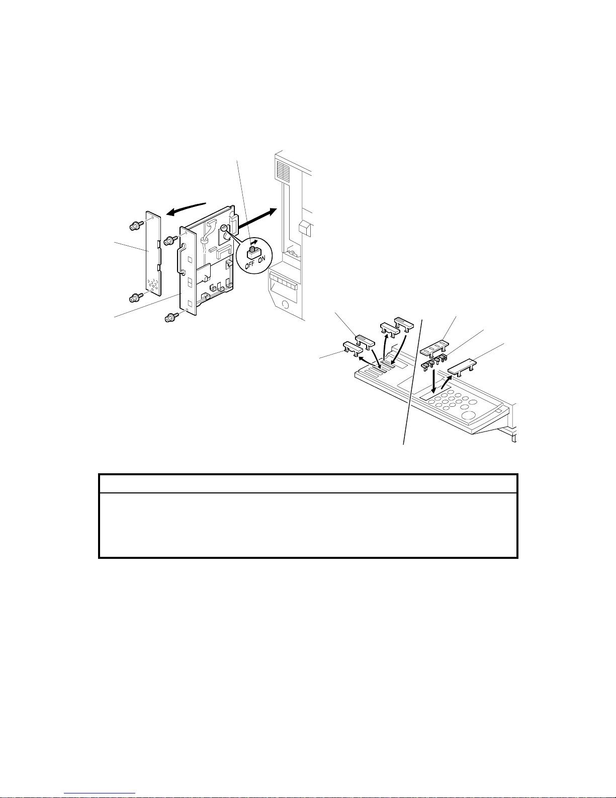
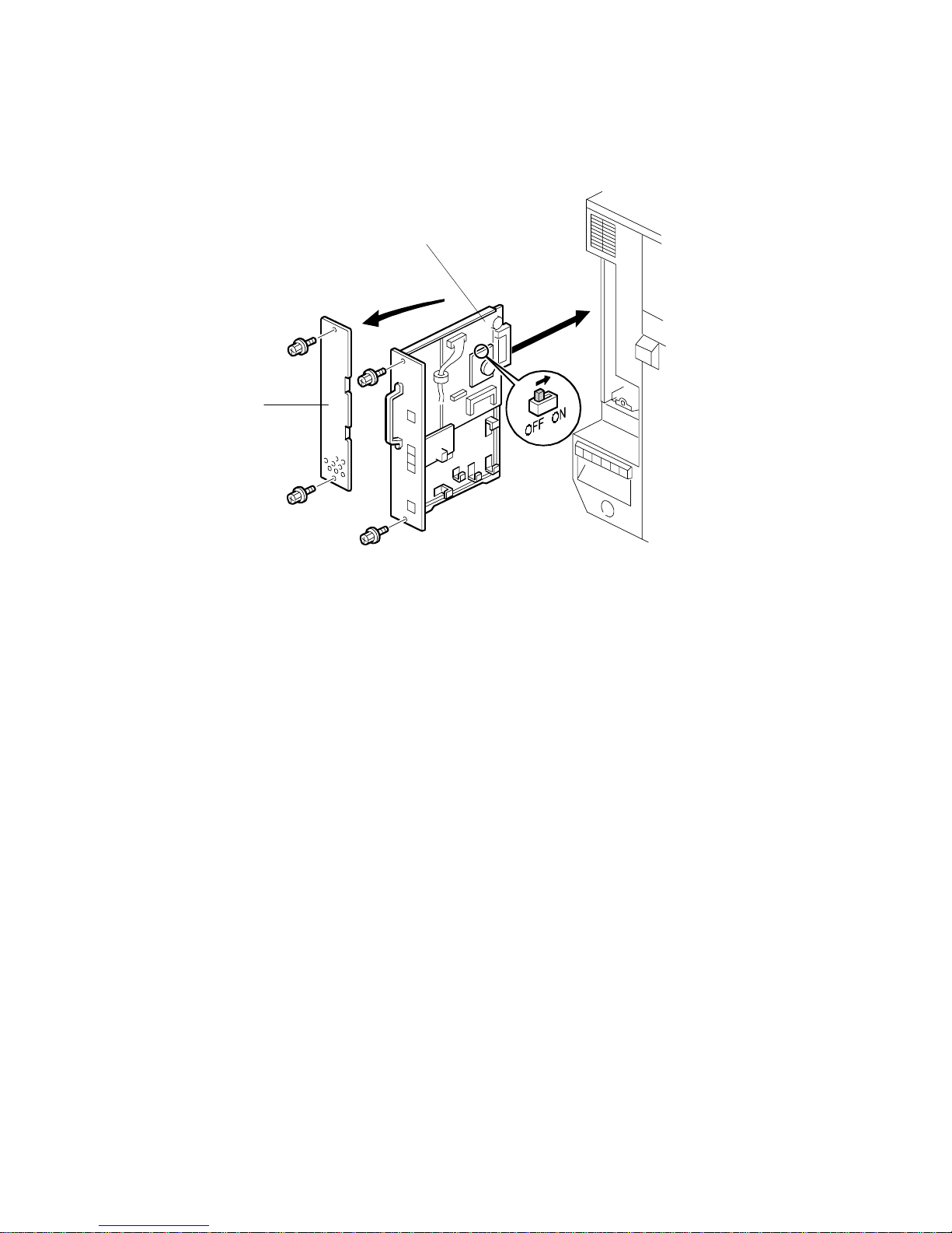
1. Remove the rear left cover plate [A] (! x 2).
2. Turn on the DIP switch [B] on the MBU board, then install the fax unit [C]
(! x 2).
NOTE: Make sure that the controlle r unit is installed when inserting the fax
unit. If the controller unit is installed after the fax unit has been
installed, this may cause poor connection between the fax unit and
controller unit.
3. Remove the cover key tops [D] and install key tops [E]/[F] and cover [G].
4. Attach the FCC decal (only for US/Canada) to the rear cover.
G307I501.WMF
G307I104.WMF
[A]
[C]
[B]
[D]
[F]
[G]
[E]
[D]
21 December, 2001 FAX UNIT
1-3
Installation
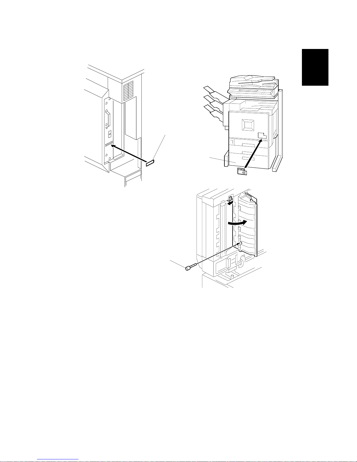
5. Attach the serial number decal [A] to the rear cover.
6. Attach the super G3 decal [B] as shown
7. If the ADF has been installed, insert the stamp cartridge [C] into the ADF as
shown.
8. Connect the telephone line to the “LINE” jack at the rear of the machine.
9. Plug in the machine and turn on the main power switch.
NOTE: The machine must be connected to a properly-grounded socket outlet.
10. Be sure to set the clock. (Date and time)
11. Enter service mode and program the serial number into the fax unit (SP3-102-
000). The serial number can be found on the serial number label (attached to
the machine in step 5).
G307I507.WMF
G307I105.WMF
G307I106.WMFWMF
[B]
[A]
[C]
FAX UNIT 21 December, 2001
1-4
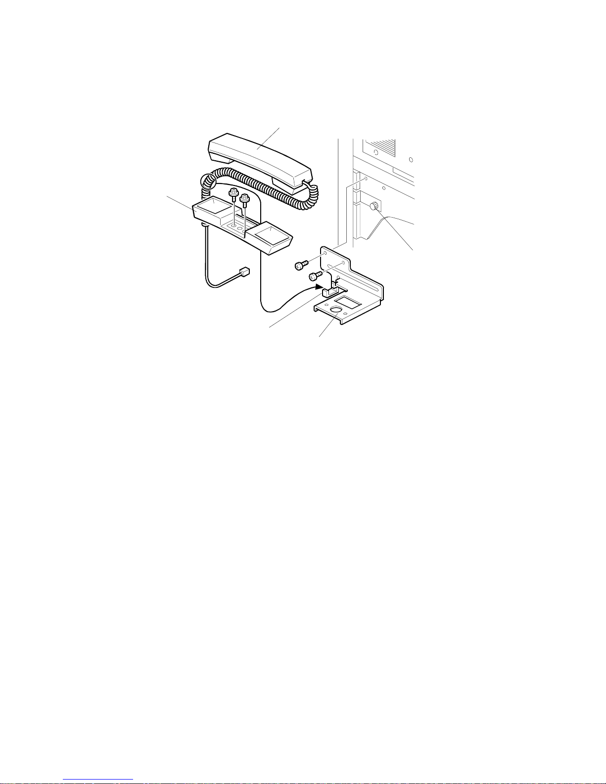
1.1.3 INSTALLING THE HANDSET
NOTE: The optional handset is for the U.S. model only.
1. Remove the thumb screw [A] on the left spacer.
2. Install the handset bracket [B] on the left arm (2 screws, 1 thumb screw).
3. Install the handset holder [C] on the bracket (2 screws).
4. Place the handset [D] with the handset cord resting on the cord holder [E] of
the bracket.
5. Connect the handset cord to the jack.
G307I114.WMF
[A]
[B]
[C]
[D]
[E]
21 December, 2001 FAX UNIT OPTIONS
1-5
Installation
1.2 FAX UNIT OPTIONS
1.2.1 G3 INTERFACE UNIT INSTALLATION
!
CAUTION
Before installing this option, do the following:
1. Print out all data in the printer buffer.
2. Turn off the main switch and disconnect the power cord and the
network.
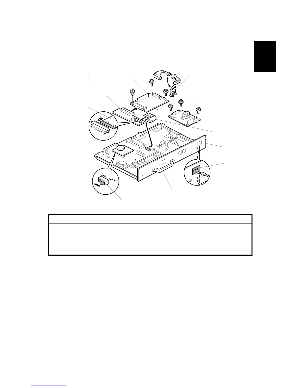
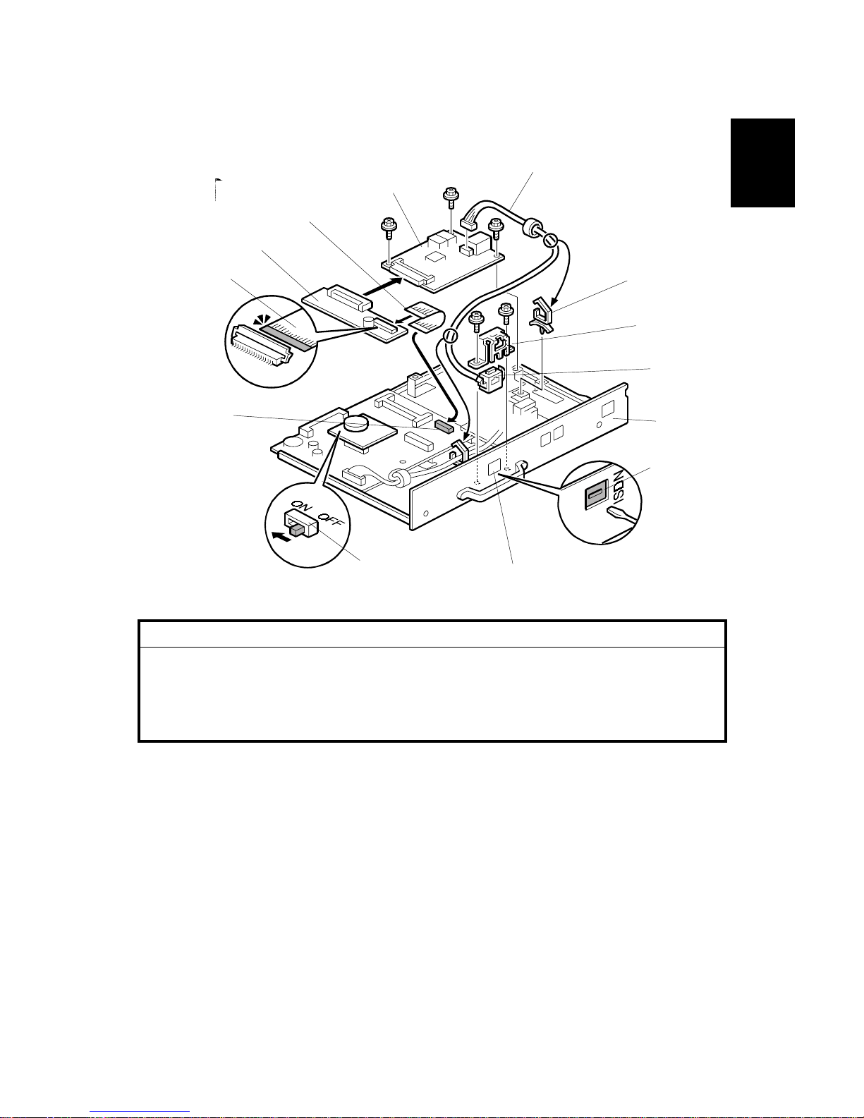
1. Remove the jack window (LINE2) [A] from the panel plate [B].
2. Install the G3 board [C] and NCU board [D] (3 screws each).
3. Attach the harness clamp [E].
4. Connect the harness [F] to the connectors on G3 and NCU boards (harness
clamp [E]).
5. Connect the flat cable [G] to the connector [H] on the FCU board.
6. Connect the I/F board [I] to the G3 board and connect the flat cable [G] to the
I/F board.
NOTE: When installing the fax unit and G3 unit simultaneously, turn on the DIP
switch [J] on the MBU board.
G307I511.WMF
[B]
[A]
[G]
[D]
[E]
[F]
[C]
[I]
[G]
[J]
[H]
FAX UNIT OPTIONS 21 December, 2001
1-6
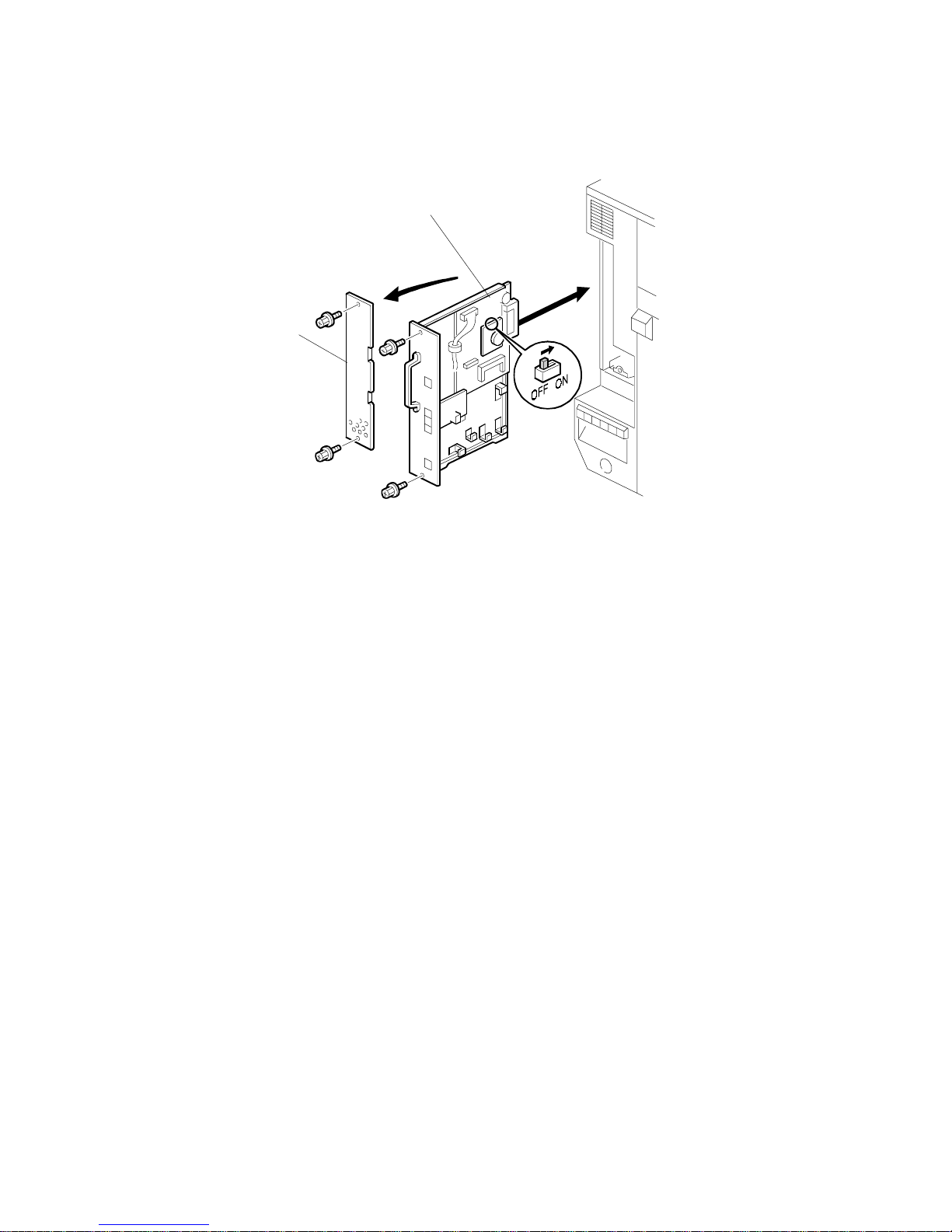
7. Remove the rear left cover plate [A] and install the fax unit [B] (2 screws each).
NOTE: Make sure that the controlle r unit is installed when inserting the fax
unit. If the controller unit is installed after the fax unit has been
installed, this may cause poor connection between the fax unit and
controller unit.
8. Connect the cable to the LINE2 jack, then plug in the machine and turn the
main switch on.
9. Attach the FCC/IC approval label to the machine near the ISDN jack (this step
is only for US/Canada).
10. Enter the service mode and set bit 1 of communication switch 16 to “1”, then
turn the main switch off and on.
11. Print the system parameter list and ensure that “SG3-V34” is listed as an
option.
12. Set up and program the items required for PSTN-2 communications.
G307I101.WMF
[A]
[B]
21 December, 2001 FAX UNIT OPTIONS
1-7
Installation
1.2.2 ISDN OPTION INSTALLATION
!
CAUTION
Before installing this option, do the following:
1. Print out all data in the printer buffer.
2. Turn off the main switch and disconnect the power cord and the
network cable.
1. Remove the jack window (ISDN) [A] from the panel [B].
2. Install the G4 unit [C] (3 screws) and harness clamp.
3. Connect the flat cable [D] to the connector [E] on the FCU board.
4. Connect the I/F board [F] to the G4 unit and connect the flat cable [D] to the I/F
board.
5. Attach the modular socket [G] to the bracket [H] and install the bracket (2
screws).
6. Connect the cable [I] to the G4 unit and route the cable (2 clamps [J]).
NOTE: When installing the fax unit and G4 unit simultaneously, turn on the DIP
switch [K] on the MBU board.
G307I521.WMF
[K]
[C]
[D]
[F]
[A]
[B]
[J]
[J]
[I]
[H]
[D]
[E]
[G]
FAX UNIT OPTIONS 21 December, 2001
1-8
7. Remove the rear left cover [A] and install the fax unit [B] (! x 2 each).
NOTE: Make sure that the controller unit is installed when inserting the fax
unit.
If the controller unit is installed after the fax unit has been installed, this
may cause poor connection between the fax unit and controller unit.
8. Connect the cable to the ISDN jack, then plug in the machine and turn the main
switch on.
9. Attach the FCC/IC approval label to the machine near the ISDN jack (this step
is only for US/Canada).
10. Enter service mode and set bit 2 of communication switch 16 to "1". After that,
turn the main switch off and on.
11. Print the system parameter list and ensure that "G4" is listed as an option.
12. Set up and program the items required for ISDN communications. After setting
up the ISDN parameters, be sure to turn the main switch off and on.
G307I101.WMF
[A]
[B]
21 December, 2001 FAX UNIT OPTIONS
1-9
Installation
1.2.3 FAX FUNCTION UPGRADE UNIT INSTALLATION
!
CAUTION
Before installing this option, do the following:
1. Print out all data in the printer buffer.
2. Turn off the main switch and disconnect the power cord and the
network cable.
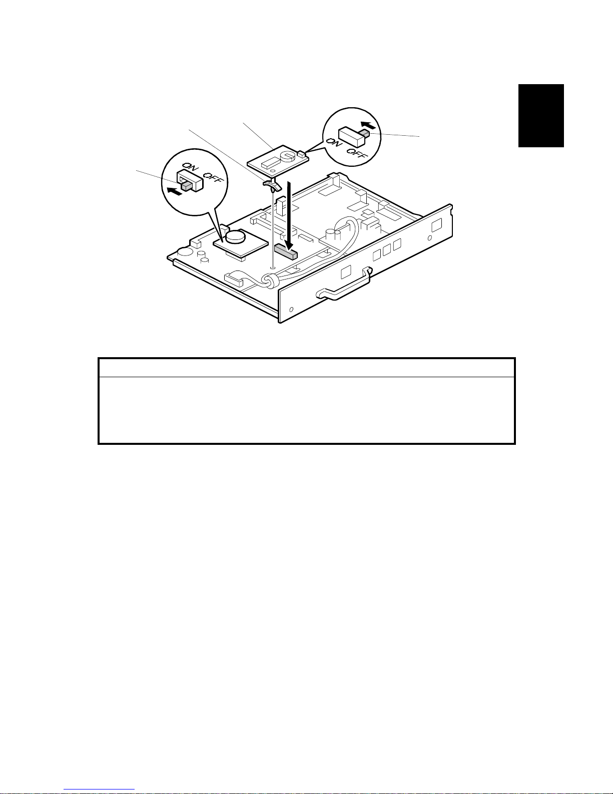
1. Turn on the DIP switch [A] on the fax function upgrade unit [B].
2. Attach the stand [C] to this unit.
3. Connect the fax function upgrade unit to CN621 and attach the stand to the
board.
4. Turn the main switch off and on.
5. Enter service mode and set bit 7 of system switch 1E to “1”
NOTE: When installing the fax unit and f ax function upgrade unit at the same time,
turn on the DIP switch [D] on the MBU board.
G307I103.WMF
[A]
[B]
[C]
[D]
FAX UNIT OPTIONS 21 December, 2001
1-10
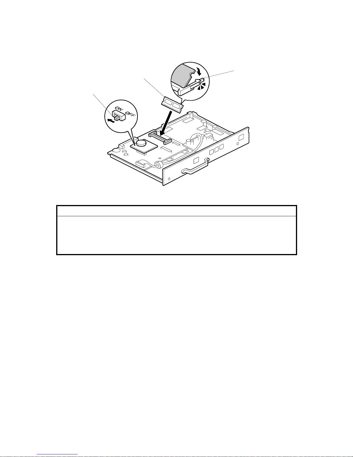
1.2.4 EXPANSION MEMORY INSTALLATION
!
CAUTION
Before installing this option, do the following:
1. Print out all data in the printer buffer.
2. Turn off the main switch and disconnect the power cord and the
network cable.
1. Slide the expansion memory [A] into the CN602 slot and tilt it down until it is
locked by the pin [B].
NOTE: When installing the fax unit and expansion memory at the same time, turn
on the DIP switch [C] on the MBU board.
G307I102.WMF
[A]
[C]
[B]

21 December, 2001 ERROR CODES
2-1
Trouble-
shooting
2. TROUBLESHOOTING
2.1 ERROR CODES
If an error code occurs, retry the communication. If the same problem occurs, try to
fix the problem as suggested below. Note that some error codes appear only in the
error code display and on the service report.
Code Meaning Suggested Cause/A c ti on
0-00 DIS/NSF not detecte d w it hin
40 s of Start being pressed
• Check the line connection.
• Check the NCU - FCU connectors.
• The machine at the other end may be
incompatible.
• Replace the NCU or FCU.
• Check for DIS/NSF with an oscilloscope.
• If the rx signal is weak, there may be a bad line.
0-01 DCN received unexpectedly
• The other party is out of paper or has a jammed
printer.
• The other party pressed Stop during
communication.
0-03 Incompatible mode m at t he
other end
• The other terminal is incompat ible.
0-04 CFR or FTT not received
after modem training
• Check the line connection.
• Check the NCU - FCU connectors.
• Try changing the tx level and/or ca bl e equalizer
settings.
• Replace the FCU or NCU.
• The other terminal may be faulty ; try sending to
another machine.
• If the rx signal is weak or defective, there may be
a bad line.
Cross reference
• Tx level - NCU Par ameter 01 (PSTN)
• Cable equalizer - G 3 Switch 07 (PSTN)
• Dedicated Tx parameters - Section 4
0-05 Unsuccessful after modem
training at 2400 bps
• Check the line connection.
• Check the NCU - FCU connectors.
• Try adjusting the tx level and/or cable equalizer.
• Replace the FCU or NCU.
• Check for line problems.
Cross reference
• See error code 0-04.

ERROR CODES 21 December, 2001
2-2
Code Meaning Suggested Cause/A c ti on
0-06 The other terminal did not
reply to DCS
• Check the line connection.
• Check the FCU - NCU connectors.
• Try adjusting the tx level and/or cable equalizer
settings.
• Replace the NCU or FCU.
• The other end may be defective or incompatible;
try sending to another machine.
• Check for line problems.
Cross reference
• See error code 0-04.
0-07 No post-message response
from the other end after a
page was sent
• Check the line connection.
• Check the FCU - NCU connectors.
• Replace the NCU or FCU.
• The other end may have jammed or run out of
paper.
• The other end user may have disconne ct ed t he
call.
• Check for a bad line.
• The other end may be defective; t ry sending to
another machine.
0-08 The other end sent RTN or
PIN after receiving a page,
because there were too
many errors
• Check the line connection.
• Check the FCU - NCU connectors.
• Replace the NCU or FCU.
• The other end may have jammed, or run out of
paper or memory space.
• Try adjusting the tx level and/or cable equalizer
settings.
• The other end may have a defective
modem/NCU/FC U; t r y sending to another
machine.
• Check for line problems and noise.
Cross reference
• Tx level - NCU Par ameter 01 (PSTN)
• Cable equalizer - G 3 Switch 07 (PSTN)
• Dedicated Tx parameters - Section 4
0-14
Non-standard post message
response code received
• Check the FCU - NCU connectors.
• Incompatible or defective remote terminal; try
sending to another machine.
• Noisy line: resend.
• Try adjusting the tx level and/or cable equalizer
settings.
• Replace the NCU or FCU.
Cross reference
• See error code 0-08.

21 December, 2001 ERROR CODES
2-3
Trouble-
shooting
Code Meaning Suggested Cause/A c ti on
0-15 The other terminal is not
capable of specific
functions.
The other terminal is not capabl e of a ccepting the
following functions, or the other termin al ’s me mory
is full.
• Confidential rx
• Transfer function
• SEP/SUB/PWD/SID
0-16 CFR or FTT not detected
after modem training in
confidential or transfer mode
• Check the line connection.
• Check the FCU - NCU connectors.
• Replace the NCU or FCU.
• Try adjusting the tx level and/or cable equalizer
settings.
• The other end may have disconnect ed, or it may
be defective; try calling another machine.
• If the rx signal level is too low, there may be a
line problem.
Cross reference
• See error code 0-08.
0-17 Communication was
interrupted by pressing the
Stop key.
If the Stop key was not pressed and this error keeps
occurring, replace the operation panel.
0-20 Facsimile data not receiv ed
within 6 s of retraining
• Check the line connection.
• Check the FCU - NCU connectors.
• Replace the NCU or FCU.
• Check for line problems.
• Try calling another fax machine.
• Try adjusting the reconstruction time for the first
line and/or rx cable equaliz er set t ing.
Cross reference
• Reconstruction time - G3 Switch 0A, bit 6
• Rx cable equalizer - G3 Switch 07 (PSTN)
0-21 EOL signal (end-of-line)
from the other end not
received within 5 s of the
previous EOL signal
• Check the connections between the FCU, NCU,
& line.
• Check for line noise or other line pro bl ems.
• Replace the NCU or FCU.
• The remote machine may be defective or may
have disconnected.
Cross reference
• Maximum interval between EOLs and between
ECM frames - G3 Bit Switch 0A, bit 4
0-22 The signal from the other
end was interrupted for
more than the acceptable
modem carrier drop time
(default: 200 ms)
• Check the line connection.
• Check the FCU - NCU connectors.
• Replace the NCU or FCU.
• Defective remote terminal.
• Check for line noise or other line pro bl ems.
• Try adjusting the acceptable mode m carrier drop
time.
Cross reference
• Acceptable modem carrier drop time - G3 Sw it ch
0A, bits 0 and 1

ERROR CODES 21 December, 2001
2-4
Code Meaning Suggested Cause/A c ti on
0-23 Too many errors during
reception
• Check the line connection.
• Check the FCU - NCU connectors.
• Replace the NCU or FCU.
• Defective remote terminal.
• Check for line noise or other line pro bl ems.
• Try asking the other end to adjust their tx level.
• Try adjusting the rx cable equalizer set t ing an d/ or
rx error criteria.
Cross reference
• Rx cable equalizer - G3 Switch 07 (PSTN)
• Rx error criteria - Communication Switch 02, bits
0 and 1
0-30 The other terminal did not
reply to NSS(A) in AI short
protocol mode
• Check the line connection.
• Check the FCU - NCU connectors.
• Try adjusting the tx level and/or cable equalizer
settings.
• The other terminal may not be comp atible.
Cross reference
• Dedicated tx parameters - Section 4
0-32 The other terminal sent a
DCS, which contained
functions that the receiving
machine cannot handle.
• Check the protocol dump list.
• Ask the other party to contact the manufacturer.
0-52 Polarity changed durin g
communication
• Check the line connection.
Retry communication.
0-70 The communication mode
specified in CM/JM was not
available
(V.8 calling and called
terminal)
• The other terminal did not have a co mpat ible
communication mode (e.g., t he ot her t erminal
was a V.34 data modem and not a fax mo dem.)
• A polling tx file was not ready at t he ot her
terminal when polling rx was in it iated from the
calling terminal.
0-74
The calling terminal fell back
to T.30 mode, because it
could not detect ANSam
after sending CI.
• The calling terminal coul d not det ect ANSam due
to noise, etc.
• ANSam was too short to detect.
• Check the line connection an d condition.
• Try making a call to another V.8/V. 34 fax.
0-75
The called terminal fell back
to T.30 mode, because it
could not detect a CM in
response to ANSam
(ANSam timeout).
• The terminal could not detect A NS am.
• Check the line connection an d condition.
• Try receiving a call from another V.8/V.34 fax.
0-76 The calling terminal fell back
to T.30 mode, because it
could not detect a JM in
response to a CM
(CM timeout).
• The called terminal could not detect a CM due to
noise, etc.
• Check the line connection an d condition.
• Try making a call to another V.8/V. 34 fax.

21 December, 2001 ERROR CODES
2-5
Trouble-
shooting
Code Meaning Suggested Cause/A c ti on
0-77 The called terminal fell back
to T.30 mode, because it
could not detect a CJ in
response to JM
(JM timeout).
• The calling terminal could not det ect a JM due to
noise, etc.
• A network that has narrow bandwidth cannot
pass JM to the other end.
• Check the line connection an d condition.
• Try receiving a call from another V.8/V.34 fax.
0-79 The called terminal detected
CI while waiting for a V.21
signal.
Check for line noise or other line problems.
If this error occurs, the called terminal falls back to
T.30 mode.
0-80
The line was disconnected
due to a timeout in V.34
phase 2 – line probing.
0-81 The line was disconnected
due to a timeout in V.34
phase 3 – equalizer trainin g.
0-82 The line was disconnected
due to a timeout in the V.34
phase 4 – control channel
start-up.
0-83 The line was disconnected
due to a timeout in the V.34
control channel restart
sequence.
• The guard timer expired while starting these
phases. Serious noise, narrow ba ndw idth, or low
signal level can cause these errors.
If these errors happen at the transmitting t erminal:
• Try making a call at a later time.
• Try using V.17 or a slower modem using
dedicated tx parameters.
• Try increasing the tx level.
• Try adjusting the tx cable equalizer setting.
If these errors happen at the receiving t erminal:
• Try adjusting the rx cable equalizer set t ing.
• Try increasing the tx level.
• Try using V.17 or a slower modem if the same
error is frequent when receiving from multiple
senders.
0-84
The line was disconnected
due to abnormal signa li ng in
V.34 phase 4 – control
channel start-up.
• The signal did not stop within 1 0 s.
• Turn off the machine, then turn it back on.
• If the same error is frequent, replace the FCU.
0-85
The line was disconnected
due to abnormal signa li ng in
V.34 control channel restart.
• The signal did not stop within 1 0 s.
• Turn off the machine, then turn it back on.
• If the same error is frequent, replace the FCU.
0-86 The line was disconnected
because the other terminal
requested a data rate using
MPh that was not available
in the currently selected
symbol rate.
• The other terminal was incompatible.
• Ask the other party to contact the manufacturer.
0-87
The control channel started
after an unsuccessful
primary channel.
• The receiving terminal restarte d t he cont rol
channel because data recept ion in the primary
channel was not successful.
• This does not result in an error communication.
0-88
The line was disconnected
because PPR was
transmitted/received 9
(default) times within the
same ECM frame.
• Try using a lower data rate at the start.
• Try adjusting the cable equalizer setting.
2-10 The modem cannot enter tx
mode
• Replace the FCU.
2-11 Only one V.21 connection
flag was received
• Replace the FCU.

ERROR CODES 21 December, 2001
2-6
Code Meaning Suggested Cause/A c ti on
2-12 Modem clock irregularity
• Replace the FCU.
2-13 Modem initialization error
• Turn off the machine, then turn it back on.
• Update the modem ROM.
• Replace the FCU.
2-20 Abnormal coding/deco ding
(cpu not ready)
• Replace the FCU.
2-23
JBIG compression or
reconstruction error
• Turn off the machine, then turn it back on.
• Replace the EXFUNC board if the error is
frequent.
2-24 JBIG ASIC error
• Turn off the machine, then turn it back on.
• Replace the EXFUNC board if the error is
frequent.
2-25 JBIG data reconstruction
error (BIH error)
2-26
JBIG data reconstruction
error (Float marker error)
2-27
JBIG data reconstruction
error (End marker error)
2-28 JBIG data reconstruction
error (Timeout)
• JBIG data error
• Check the sender’s JBIG function.
• Update the MBU ROM.
2-50 The machine resets itself for
a fatal FCU system error
• If this is frequent, update the ROM, or replace the
FCU.
2-51 The machine resets itself
because of a fatal
communication error
• If this is frequent, update the ROM, or replace the
FCU.
3-00 G4 interface board reset
• Replace the G4 interface board or FC U.
3-10 Disconnection during ISDN
G3 communication
• Check the other terminal and the ISDN line.
• The other terminal may have dia led a w rong
number.
3-11 Disconnection during ISDN
G4 communication
• Check the other terminal and the ISDN line.
3-20
A CSA signal was received
during ISDN G4
communication
• The operator at the other terminal may have
interrupted the communication.
3-21 A CSA signal was sent
during ISDN G4
communication, because t he
Stop key was pressed
• The local operator has interrupted t he
communication.
3-30 Mismatched specific ations
(rx capability)
• Check the receive capabilities re quest ed from the
other terminal.
4-01 Line current was cut
• Check the line connector.
• Check the connection between FCU and NCU.
• Check for line problems.
• Replace the FCU or the NCU.
4-10
Communication failed
because of an ID Code
mismatch (Closed Network)
or Tel. No./CSI mismatch
(Protection against Wrong
Connections)
• Get the ID Codes the same and/or the CSIs
programmed correctly, then resend.
• The machine at the other end may be defective.
21 December, 2001 ERROR CODES
2-7
Trouble-
shooting
Code Meaning Suggested Cause/A c ti on
5-00 Data construction not
possible
5-01 Data reconstruction not
possible
5-10 DCR timer expired
• Replace the FCU.
5-20 Storage impossible becaus e
of a lack of memory
• Temporary memory shortage.
• Test the SAF memory.
• Replace the FCU or optional EXMEM board
5-21 Memory overflow
5-22 Mode table overflow after
the second page of a
scanned document
• Wait for the messages which are currently in the
memory to be sent or delete some files from
memory.
5-23 Print data error when
printing a substitute rx or
confidential rx messag e
• Test the SAF memory.
• Ask the other end to resend the message.
• Replace the FCU or optional EXMEM board.
5-24 Memory overflow after the
second page of a scanned
document
• Try using a lower resolution setting.
• Wait for the messages which are currently in the
memory to be sent or delete some files from
memory.
5-25 SAF file access error
• Replace the FCU or EXMEM board.
6-00 G3 ECM - T1 time out
during reception of facsim ile
data
6-01
G3 ECM - no V.21 signal
was received
6-02
G3 ECM - EOR was
received
• Try adjusting the rx cable equalizer.
• Replace the FCU or NCU.
6-04 G3 ECM - RTC not detected
• Check the line connection.
• Check connections from the NCU to the FCU.
• Check for a bad line or defective remote term inal.
• Replace the FCU or NCU.
6-05 G3 ECM - facsimile data
frame not received within 18
s of CFR, but there was no
line fail
• Check the line connection.
• Check connections from the NCU to the FCU.
• Check for a bad line or defective remote term inal.
• Replace the FCU or NCU.
• Try adjusting the rx cable equaliz er
Cross reference
• Rx cable equalizer - G3 Switch 07 (PSTN)
6-06 G3 ECM - coding/decoding
error
• Defective FCU.
• The other terminal may be defectiv e.
6-08 G3 ECM - PIP/PI N received
in reply to PPS.N ULL
• The other end pressed Stop during
communication.
• The other terminal may be defectiv e.
6-09 G3 ECM - ERR received
• Check for a noisy line.
• Adjust the tx levels of the communicating
machines.
• See code 6-05.

ERROR CODES 21 December, 2001
2-8
Code Meaning Suggested Cause/A c ti on
6-10 G3 ECM - error frames still
received at the other end
after all communication
attempts at 2400 bps
• Check for line noise.
• Adjust the tx level (use NCU parameter 01 or the
dedicated tx parameter for that addres s).
• Check the line connection.
• Defective remote terminal.
6-21 V.21 flag detected during
high speed modem
communication
• The other terminal may be defectiv e or
incompatible.
6-22
The machine resets the
sequence because of an
abnormal handshake in the
V.34 control channel
• Check for line noise.
• If the same error occurs frequently, replace t he
FCU.
• Defective remote terminal.
6-99 V.21 signal not stopped
within 6 s
• Replace the FCU.
22-00 Original length exceeded the
maximum scan length
• Divide the original into more than one page.
• Check the resolution used for scanning. Lower
the scan resolution if possible.
• Add optional page memory.
22-01 Memory overflow while
receiving
• Wait for the files in the queue to be sent .
• Delete unnecessar y files from memory.
• Transfer the substitute reception files to an
another fax machine, if the machine’s printer is
busy or out of order.
• Add an optional SAF memory card or hard disk.
22-02 Tx or rx job stalled due to
line disconnection at the
other end
• The job started normally but did not finish
normally; data may or may not have been
received fully.
• Restart the machine.
22-04 The machine cannot store
received data in the SAF
• Update the ROM
• Replace the FCU.
23-00 Data read timeout during
construction
• Restart the machine.
• Replace the FCU
25-00 The machine software
resets itself after a fatal
transmission error occurred
• Update the ROM
• Replace the FCU.
F0-xx V.34 modem error
• Replace the FCU.
F6-8x SG3-V34 modem error
• Update the SG3-V34 modem ROM.
• Replace the SG3-V34 boar d.
• Check for line noise or other line pro bl ems.
• Try communicating another V.8/V.34 fax.

21 December, 2001 ERROR CODES FOR THE ISDN OPTION
2-9
Trouble-
shooting
2.2 ERROR CODES FOR THE ISDN OPTION
The tables on the following pages show the error codes for the ISDN option.
The meaning of the numbers in the Action column is as follows.
1. Check Layer 1 signaling with a protocol analyzer to determine the cause of the
problem. This may require assistance from a G4 specialist.
2. Repeat the communication. If the problem does not repeat itself, the problem
was a temporary one caused by the user connecting the machine to another
interface. However, if the problem remains, there is a network problem.
3. There is a network problem.
4. There is a network problem. Do the following:
• Check the error bit rate of the network. If it is high, contact the network and
ask them to improve the line.
• Check the network speed (is it 56 or 64 kbps), and make sure that the bit
switch setting is correct. You may also use the dedicated transmission
parameters if this problem only occurs when dialing certain numbers.
• Check that the user dialed the correct number.
5. There is a network problem, or a problem in the machine at the other end.
6. There is a problem in the machine at the other end; ask a technician to check it.
7. The machine at the other end is not a Group 4 fax terminal.
8. The machine is not compatible with the machine at the other end. A
compatibility test is needed.
Error codes related to the errors detected by the FCU are listed in the service
manual of the main body.
ERROR CODES FOR THE ISDN OPTION 21 December, 2001
2-10
2.2.1 D-CHANNEL LAYER MANAGEMENT
Code Probable Cause Action
7-00 Link reset 2
7-01 Link set-up failed because of time-o ut . 2
7-02 Link release failed because of ti me-out . 2
7-03 Link set-up parameter error 2
2.2.2 D-CHANNEL, LAYER 1
Code Probable Cause Action
7-10 T3 timeout (layer 1 activation error) 1
7-11 No connection on the S0 interface 1
7-12 Deactivated 1
2.2.3 D-CHANNEL LINK LAYER
Code Probable Cause Action
7-20 At the start of link set-up, the ma chi ne received an unsolicited S (F= 1). 2
7-21 At the start of link set-up, the ma chine received an unsolicited DM
(F=1).
2
7-22 At TEI release, the machine received an unsolicited U A (F=1). 2
7-23 At the start of link set-up, the ma chine received an unsolicited DM
(F=0).
2
7-24 At TEI release, the machine received an unsolicited U A (F=0). 2
7-25 SABME received at the start of network link set-up No error
7-26 N200 retransmission error for SABME 2
7-27 N200 retransmission error for DISC 2
7-28 N200 retransmission error for situation enquiry (RR) 2
7-29 N(R) sequence number error 3
7-30 N(S) sequence number error 3
7-31 FRMR received 3
7-32 Non-standard frame receiv ed 3
7-33 Abnormal frame length 3
7-34 N201 error; information field N in the I frame exceeded N201 3
7-35 T201 timeout; timeout whi le waiting for checking 3
7-36 T202 timeout; timeout whi le w aiting for ID assignment 3
21 December, 2001 ERROR CODES FOR THE ISDN OPTION
2-11
Trouble-
shooting
2.2.4 D-CHANNEL NETWORK LAYER
Code Probable Cause Action
7-40 Insufficient mandatory information elements 3
7-41 Abnormal LI for a mandatory inf ormation element 3
7-42 T301 timeout; timeout while waiting for R:CONN 3
7-43 T303 timeout; timeout while waiting for R: CALL-PROC etc. 3
7-44 T304 timeout; timeout while waiting for R: CALL-PROC etc. 3
7-45 T305 timeout; timeout while waiting for R:REL 3
7-46 T308 timeout; timeout w hile waiting for R:REL-COMP 3
7-47 T310 timeout; timeout w hi le w aiting for R: ALERT etc. 3
7-48 T313 timeout; timeout w hile waiting for R:CONN-ACK 3
7-49 Internal error 3
7-51 Release call reference during communication 3
2.2.5 B-CHANNEL LINK LAYER
Code Probable Cause Action
7-60 T3 timeout; timeout while wait ing for flag 4
7-61 T3 timeout; timeout while wait ing for SABM during an incoming ca ll 4
7-62 T1 timeout x N2; timeout while waiting for UA after sending SABM 5
7-63
T1 timeout x N2; timeout whi le waiting for a response to a transmitt ed
S frame (P=1)
5
7-64 T1 timeout x N2; timeout while waiting for SABM or DISC after sending
FRMR
5
7-65 T1 timeout x N2; timeout whi le w aiting for a response to DISC 5
7-66 RNR x N2 (other end busy, RCB counter error) 5
7-67 Invalid (Ad) frame received 5
7-68 Invalid short frame received 5
7-69 Link reset error 5
7-70 FRMR received 5
7-71 Non-standard (Cn) frame receiv ed 5
7-72 An S or U frame having an information field was receive d 5
7-73 A frame longer than the maximum N1 length was received 5
7-74 An S or I frame having an N(R) error was received 5
7-75 CRC error 3
ERROR CODES FOR THE ISDN OPTION 21 December, 2001
2-12
2.2.6 B-CHANNEL NETWORK LAYER
Code Probable Cause Action
7-80 A packet having an abnormal G FI was received 6
7-81 A packet was received that had a l ogi cal channel number different
from the logical channel be ing used for the communication
6
7-82 A packet containing a format error was receiv ed 6
7-83 A packet containing an LI error was receiv ed 7
7-84 A CN packet was received that had a PID different from 02 7
7-85 Unsupported packet type received 7
7-86 Abnormal or unsupported fac ility received 7
7-87 P(s) sequence number error 6
7-88 P(r) sequence number error 6
7-89 A reset using S:RQ or R:RI occurred 6
7-90 A restart using S:RQ or R:SI occurred 6
7-91 Call set-up err or; in reply to S:CR, R:CI was receiv ed to indicate
rejection of the call
7
7-92 T20 timeout; timeout while w ait ing for an SF packet 6
7-93 T21 timeout; timeout while w ait ing for a CC packet 6
7-94 T22 timeout; timeout while w ait ing for an RF packet 6
7-95 T23 timeout; timeout while w ait ing for a CF packet 6
7-96 T10 timeout; timeout while w ait ing for the first frame 6
2.2.7 TRANSPORT LAYER
Code Probable Cause Action
8-00 Invalid block received 8
8-01 TCC block received 8
8-02 TBR block received 8
8-05 TCR block; block format error 8
8-06 TCR block; block size paramet er LI error 8
8-07 TCR block; extended addressing LI error 8
8-08 TCR block; block size length error 8
8-10 TCA block; block format error 8
8-11 TCA block; Tx origin reference d ata in TCR disagreed with the addre ss
reference data in TCA
8
8-12 TCA block; octet 7 did not equal 0 8
8-13 TCA block; extended address ing LI error 8
8-14 TCA block; block size exceeded that set by TCR 8
8-15 TCA block; block size parameter LI error 8
8-20 TDT block; block format error 8
8-21 TDT block; octet 3 did not equal either 00 or 80(H) 8
8-22 TDT block; the end indicat or w as “Continue” even though there was no
field data
8
8-23 TDT block; an end block with no field data was received after an end
indicator of “End”
8
8-26 Timeout during state 0.2 8
8-27 Timeout during state 1.1 8
8-28 Timeout during state 0.3 8

21 December, 2001 ERROR CODES FOR THE ISDN OPTION
2-13
Trouble-
shooting
2.2.8 SESSION LAYER
Code Probable Cause Action
8-30 Invalid frame received 8
8-31 RSSN received 8
8-32 CSA received 8
8-34 Calling terminal ident i fication error in CSS 8
8-35 Date and time error in CSS 8
8-36 Window size error in CSS 8
8-37 Service identification error in CSS 8
8-38 Session user data error in CSS 8
8-39 CSS rejected (new session rejected) 8
8-40 Called termin al identificatio n error in RSSP 8
8-41 Date and time error in RSSP 8
8-42 Date and time in RSSP was n ot t he same as that in CSS 8
8-43 Window size error in RSSP 8
8-44 Service identification error in RSSP 8
8-45 Session user data error in RSSP 8
8-47 Message synchronization error inside the CCU 8
8-48 Document task busy 8
8-50 Ti timeout; non-communicat ion surveillance timer (T.62) 8
8-51 T2 timeout; timeout while wait ing for a response (T.62) 8
8-52 T3 timeout; CSA timer timeout (T.62) 8
8-53 G4 board load timer timeout; calling side waited too long for a new
session
8
8-54 G4 board load timer timeout; calling side waited too long for transport
probability
8
8-55 G4 board load timer timeout; called side waited too long for S:RS SP 8
8-56 G4 board load timer timeout; document t r ansmission surveillance timer
timeout
8
8-57 G4 board load timer timeout; timeout whi le waiting for a user abort
request after a provider fail
8
ERROR CODES FOR THE ISDN OPTION 21 December, 2001
2-14
2.2.9 DOCUMENT LAYER
Code Probable Cause Action
8-60 T.62 coding format error (LI error) 8
8-61 A mandatory PI was absent, or the LI for a man dat ory PI was 0 8
8-62
Calling/called terminal identification LI was different from that specified
by F.184 (LI = 24)
8
8-63 The LI for session user data exceeded the maximum value (512) 8
8-64 The LI for CDUI was not 0 8
8-65 Checkpoint and document reference n umbers LI error, or they were
not in T.61 (ASCII) coding
8
8-66 The checkpoint reference nu mber differed from the expected value 8
8-70 RDGR received 8
8-71 A non-standard PDU was rece ived while in calling mode 8
8-72 A non-standard PDU was rece ived while in called mode 8
8-73 Abnormal PDU receiv ed while in calling state ds1 8
8-74 15 consecutive CDCL signals received 8
8-75 Session window size control error (size not equal to 0) 8
8-76 Internal error 8
2.2.10 PRESENTATION LAYER
Code Probable Cause Action
8-80 X.209 coding error in session user data (LI error) 8
8-81 PV error in session user data 8
8-82 PI error in session user data 8
8-83 The capabilities in the session user data of CDS/CDC were not the
same as those in RDCLP
8
8-84 X.209 coding error in the DP (LI error) 8
8-85 X.209 coding error in the SLD (document descriptor/page descriptor)
(LI error)
8
8-86 SLD object type absent 8
8-87 PI error in the SLD (document descriptor/ page descriptor) 8
8-88
The capabilities in the SLD (do cument descriptor/page descriptor) are
duplicated or are not the same as thos e in RDCLP
8
8-89 No document descriptor at the start of the document 8
8-90 No page descriptor at the start of the page 8
8-91 Page descriptor PV error 8
8-92 X.209 coding error in the TU (LI error) 8
8-93 The TU was absent 8
8-94 PV error in the TU 8
8-95 TI error 8
8-96 X.209 coding nest level >> 8, or an LI form error 8
8-97 CDPB/CDE received while TU/TI not yet completed, or an unexpected
PDU was received while analyzing an SLD
8

21 December, 2001 FAX SC CODES
2-15
Trouble-
shooting
2.3 FAX SC CODES
2.3.1 OVERVIEW
When the FCU detects a Fax SC Code condition other than SC1201 and SC1207,
it resets itself automatically (default setting). This initializes the FCU without
erasing files in the SAF memory or resetting the switches.
NOTE: For details on Fax SC Codes 1201 and 1207, refer to the following
sections.
If bit 7 of System Switch 1F is changed to “1”, when the FCU detects a Fax SC
Code condition, it displays the code on the display and stops working until the fax
unit is initialized using one of the following methods:
• Hold down the “7” and “9” keys for more than 10 s.
• Turn off the main power switch and turn it back on.
2.3.2 SC1201
When the FCU detects an unrecoverable error in the SRAM, which requires a
complete SRAM initialization, the fax unit displays this SC Code and stops.
There is no way to recover from this error condition without a complete SRAM
initialization (all the user and service programmed data will be erased).
The possible causes are:
• SRAM backup battery defect, or SW1 on the MBU is at the “OFF” position
• SRAM on the MBU has a physical defect
• Flash memory card connection was loose
2.3.3 SC1207
This is the same as SC1201 except the error location is the SRAM on the Fax
Function Upgrade board.
The possible causes are:
• SRAM backup battery defect, or SW1 on the Fax Function Upgrade board is at
the “OFF” position.
• SRAM on the Fax Function Upgrade board has a physical defect.
• The Fax Function Upgrade board connection was loose.

FAX SC CODES 21 December, 2001
2-16
2.3.4 FAX SC CODE TABLE
SC Code Description
Suggested
Action
Sys Switch
1F bit 7 = 0
Sys Switch
1F bit 7 = 1
1101 FCU error Initialize the fax unit.
(See section 2.3.1.for
the initialization
procedure)
Automatic
reset
1201 Unrecoverable FCU -
SRAM error
Refer to section 2.3.2.
“Service Call”
display
1207
Unrecoverable Fax
Function Upgrade SRAM error
Refer to section 2.3.3.
“Service Call”
display
1299
1305
1310
1311
1312
1401
1405
Software error Initialize the fax unit.
Automatic
reset
SC Code
display

21 December, 2001 ISDN TEST FUNCTIO N
2-17
Trouble-
shooting
2.4 ISDN TEST FUNCTION
2.4.1 LEDS
There are four LEDs on the G4 board. These LEDs show the status of the
machine.
LED 1 LED 2 LED 3 LED 4
Initial Settings O=ON, --=OFF
Initial check (if the flash RO M i s updated) O O O O
Handshaking with the FCU ready O O -- --
Standby Mode
Ready to communicate -- -- -- --
Communication
Layer 1 activated -- -- -- O
Link setup -- -- O O
B channel 1 connected -- O O O
B channel 2 connected O -- O O
 Loading...