

Ricoh G186, Aficio SP 5100N Service Manual

G186
SERVICE MANUAL
003108MIU


G186
SERVICE MANUAL


G186
SERVICE MANUAL
003108MIU


It is the reader's responsibility when discussing the information contained
within this document to maintain a level of confidentiality that is in the best
interest of Ricoh Corporation and its member companies.
NO PART OF THIS DOCUMENT MAY BE REPRODUCED IN ANY
FASHION AND DISTRIBUTED WITHOUT THE PRIOR
PERMISSION OF RICOH CORPORATION.
All product names, domain names or product illustrations, including
desktop images, used in this document are trademarks, registered
trademarks or the property of their respective companies.
They are used throughout this book in an informational or editorial fashion
only and for the benefit of such companies. No such use, or the use of
any trade name, or web site is intended to convey endorsement or other
affiliation with Ricoh products.
© 2007 RICOH Corporation. All rights reserved.


The Service Manual contains information
regarding service techniques, procedures,
processes and spare parts of office equipment
distributed by Ricoh Corporation. Users of this
manual should be either service trained or
certified by successfully completing a Ricoh
Technical Training Program.
Untrained and uncertified users utilizing
information contained in this service manual to
repair or modify Ricoh equipment risk personal
injury, damage to property or loss of warranty
protection.
Ricoh Corporation
WARNING


LEGEND
PRODUCT
CODE
COMPANY
GESTETNER LANIER RICOH SAVIN
G186
SP 5100N
(RLA only)
SP 5100N Aficio SP 5100N SP 5100N
DOCUMENTATION HISTORY
REV. NO. DATE COMMENTS
*
04/2007 Original Printing
Rev. 04/2007


SM i G186
G186
TABLE OF CONTENTS
INSTALLATION
1. INSTALLATION ........................................................................... 1-1
1.1 INSTALLATION REQUIREMENTS ............................................................1-1
PREVENTIVE MAINTENANCE
2. PREVENTIVE MAINTENANCE.................................................... 2-1
2.1 PM INTERVALS .........................................................................................2-1
REPLACEMENT AND ADJUSTMENT
3. REPLACEMENT AND ADJUSTMENT ........................................ 3-1
3.1 GENERAL PRECAUTIONS ON DISASSEMBLY .......................................3-1
3.1.1 CHECK POINTS FOR SERVICING ..................................................3-1
3.1.2 RELEASING PLASTIC LATCHES.....................................................3-1
3.2 EXTERIOR COVER ...................................................................................3-2
3.2.1 COVER RIGHT..................................................................................3-2
3.2.2 REAR COVER................................................................................... 3-3
3.2.3 COVER LEFT....................................................................................3-4
3.2.4 TOP COVER .....................................................................................3-5
3.2.5 OPEN COVER...................................................................................3-7
3.2.6 INNER COVER..................................................................................3-8
3.2.7 BY-PASS TRAY ................................................................................3-9
3.3 PAPER FEED AND EXIT .........................................................................3-12
3.3.1 KNOCK UP PLATE UNIT ................................................................3-12
3.3.2 EXIT ROLLER .................................................................................3-12
3.3.3 REGISTRATION ROLLER UNIT ..................................................... 3-14
3.3.4 BY-PASS PICK UP UNIT ................................................................ 3-16
3.3.5 STOPPER ROLLER UNIT...............................................................3-19
3.3.6 IDLE ROLLER UNIT........................................................................3-19
3.3.7 PICK UP AND REGISTRATION ROLLER ......................................3-20
3.3.8 FEED ROLLER................................................................................3-23
3.3.9 RUBBER PAD .................................................................................3-24
3.4 LASER OPTICS .......................................................................................3-25
3.4.1 LSU .................................................................................................3-25
3.5 IMAGE TRANSFER..................................................................................3-26
3.5.1 TRANSFER ROLLER......................................................................3-26
CAUTIONS When Replacing a Transfer Roller ..................................3-27
3.6 FUSING ....................................................................................................3-28
3.6.1 FUSER UNIT...................................................................................3-28

G186 ii SM
3.7 DRIVE.......................................................................................................3-32
3.7.1 MAIN DRIVE UNIT .......................................................................... 3-32
3.7.2 DEVELOPMENT DRIVE UNIT ........................................................3-33
3.8 OTHERS...................................................................................................3-36
3.8.1 MAIN PCB .......................................................................................3-36
3.8.2 CONNECTOR PCB ......................................................................... 3-37
3.8.3 SOLENOIDS ...................................................................................3-38
3.8.4 DUPLEX SOLENOID.......................................................................3-40
3.8.5 HOLDER PAD UNIT........................................................................3-41
3.8.6 TONER SENSOR PCB ...................................................................3-42
3.8.7 ENGINE PCB ..................................................................................3-44
3.8.8 DC FAN ...........................................................................................3-46
TROUBLESHOOTING
4. TROUBLESHOOTING ................................................................. 4-1
4.1 PROCEDURE OF CHECKING SYMPTOMS .............................................4-1
4.2 THE CAUSES AND SOLUTIONS OF BAD IMAGES .................................4-2
4.2.1 VERTICAL BLACK LINE AND BAND................................................4-2
4.2.2 VERTICAL WHITE LINE ...................................................................4-2
4.2.3 HORIZONTAL BLACK BAND............................................................4-3
4.2.4 BLACK/WHITE SPOT .......................................................................4-4
4.2.5 LIGHT IMAGE ...................................................................................4-5
4.2.6 DARK IMAGE OR BLACK PAGE......................................................4-6
4.2.7 UNEVEN DENSITY...........................................................................4-7
4.2.8 BACKGROUND.................................................................................4-7
4.2.9 GHOST (1) ........................................................................................4-8
4.2.10 GHOST (2)...................................................................................4-9
4.2.11 GHOST (3): FUSER...................................................................4-10
4.2.12 STAINS ON THE FACE OF PAGE............................................4-10
4.2.13 STAINS ON THE BACK OF PAGE............................................4-11
4.2.14 BLANK PAGE PRINT OUT (1)...................................................4-12
4.2.15 BLANK PAGE PRINT OUT (2)...................................................4-12
4.3 THE CAUSES AND SOLUTIONS OF BAD DISCHARGE ........................ 4-14
4.3.1 WRONG PRINT POSITION ............................................................4-14
4.3.2 JAM 0 .............................................................................................. 4-14
4.3.3 JAM 1 .............................................................................................. 4-15
4.3.4 JAM 2 .............................................................................................. 4-16
4.3.5 DUPLEX JAM 1...............................................................................4-17
4.3.6 DUPLEX JAM 0...............................................................................4-18
4.3.7 MULTI-FEEDING.............................................................................4-18
4.3.8 PAPER ROLLED IN THE FUSER ...................................................4-19
4.3.9 PAPER ROLLED ON THE OPC DRUM ..........................................4-19
4.4 MALFUNCTION CAUSES AND SOLUTIONS..........................................4-21
4.4.1 FUSER ERROR ..............................................................................4-21
4.4.2 LSU (LASER SCANNING UNIT) ERROR .......................................4-21
4.4.3 MALFUNCTION OF THE GEAR OF THE FUSER DUE TO MELTING4-22
4.4.4 PAPER EMPTY...............................................................................4-22

SM iii G186
4.4.5 NO PAPER EMPTY MESSAGE......................................................4-22
4.4.6 COVER OPEN.................................................................................4-23
4.4.7 NO ERROR MESSAGE WHEN THE COVER IS OPEN ................. 4-23
4.4.8 DEFECTIVE MOTOR OPERATION ................................................ 4-24
4.4.9 NO POWER ....................................................................................4-24
4.4.10 CURVED VERTICAL LINE ........................................................ 4-25
4.5 CAUSES AND SOLUTIONS OF SOFTWARE ERRORS ......................... 4-26
4.5.1 THE PRINTER IS NOT WORKING (1)............................................4-26
4.5.2 THE PRINTER IS NOT WORKING (2)............................................4-27
4.5.3 ABNORMAL PRINTING .................................................................. 4-28
4.5.4 SPOOL ERROR ..............................................................................4-29
4.6 PERIODIC DEFECTIVE IMAGE...............................................................4-30
SERVICE TABLES
5. SERVICE TABLES....................................................................... 5-1
5.1 OVERVIEW ................................................................................................5-1
5.1.1 KEY OPERATION .............................................................................5-1
5.2 EDC (ENGINE DIAGNOSTIC CONTROL) MODE .....................................5-2
5.2.1 EDC SETUP......................................................................................5-2
5.2.2 ENTERING EDC ...............................................................................5-2
Usage ...................................................................................................5-2
5.2.3 COVER OPEN/CLOSE STATUS ......................................................5-2
Usage ...................................................................................................5-2
Function ................................................................................................5-3
5.2.4 SENSOR STATUS ............................................................................ 5-3
Usage ...................................................................................................5-3
Function ................................................................................................5-3
5.2.5 MOTOR TEST...................................................................................5-6
Usage ...................................................................................................5-6
5.2.6 FAN TEST .........................................................................................5-7
Usage ...................................................................................................5-7
Function ................................................................................................5-7
5.2.7 CLUTCH/ SOLENOID .......................................................................5-8
Usage ...................................................................................................5-8
Function ................................................................................................5-8
5.2.8 FUSER CONTROL............................................................................5-8
Usage ...................................................................................................5-9
5.2.9 LSU ...................................................................................................5-9
Usage ...................................................................................................5-9
5.2.10 DEVELOPER CONTROL ..........................................................5-10
Usage .................................................................................................5-10
Function ..............................................................................................5-10
5.2.11 CRU COUNTER ........................................................................5-11
Usage .................................................................................................5-11
Function ..............................................................................................5-12
5.2.12 PRINT TEST AND OPTION VERSION......................................5-12
Usage .................................................................................................5-12

G186 iv SM
Function ..............................................................................................5-12
5.3 FIRMWARE DOWNLOAD ........................................................................5-14
5.3.1 DOWNLOAD PROCEDURE ...........................................................5-14
DOS Command Mode.........................................................................5-14
WIM (Web Image Monitor) mode........................................................5-14
5.3.2 FIRMWARE RECOVERY PROCEDURE ........................................5-16
5.4 SAMPLE PATTERN .................................................................................5-17
5.4.1 INFORMATION PAGES ..................................................................5-17
To print information pages: ................................................................. 5-17
5.4.2 DEMO PAGES ................................................................................5-17
DETAILED SECTION DESCRIPTIONS
6. DETAILED SECTION DESCRIPTIONS ....................................... 6-1
6.1 PRINTER COMPONENTS .........................................................................6-1
6.1.1 FRONT VIEW....................................................................................6-1
6.1.2 REAR VIEW ......................................................................................6-2
6.2 SYSTEM LAYOUT .....................................................................................6-3
6.2.1 FEEDING ..........................................................................................6-3
Separation method................................................................................6-3
Basic cassette.......................................................................................6-4
Pick-up roller.........................................................................................6-4
Stopper roller ........................................................................................6-4
Registration roller.................................................................................. 6-4
By-pass tray..........................................................................................6-4
Duplex unit............................................................................................6-4
SCF (Second Cassette Feeder)............................................................6-4
6.2.2 TRANSFER .......................................................................................6-4
6.2.3 DRIVE ...............................................................................................6-5
6.2.4 FUSER .............................................................................................. 6-5
Thermostat............................................................................................6-5
Heat roller .............................................................................................6-5
Pressure roller ......................................................................................6-5
Items for safety .....................................................................................6-5
6.2.5 LSU (LASER SCANNER UNIT) ........................................................6-5
6.2.6 PRINT CARTRIDGE..........................................................................6-6
6.3 ENGINE HARDWARE SPECIFICATIONS ................................................. 6-7
6.3.1 MAIN BOARD....................................................................................6-7
Asic (ORION 2).....................................................................................6-7
Memory.................................................................................................6-8
Others ................................................................................................... 6-9
6.3.2 INTERNAL BLOCK DIAGRAM..........................................................6-9
6.3.3 SENSOR INPUT CIRCUIT ................................................................6-9
Paper Empty Sensing ...........................................................................6-9
Paper Sensing on the By-pass Tray ...................................................6-10
Paper Feeding/ Width Toner Cartridge Sensing .................................6-10
Paper Exit Sensing .............................................................................6-10
Cover Open Sensing...........................................................................6-10

SM v G186
DC Fan/ Solenoid Driving ...................................................................6-10
Motor Driving ......................................................................................6-10
6.3.4 SMPS & HVPS BOARD ..................................................................6-11
HVPS (High Voltage Power Supply) ...................................................6-11
SMPS (Switching Mode Power Supply) .............................................. 6-13
Fuser AC Power Control ..................................................................... 6-14
6.3.5 ENGINE FIRMWARE ...................................................................... 6-15
Control Algorithm ................................................................................6-15
Driver .................................................................................................. 6-16
Transfer ..............................................................................................6-16
Fusing .................................................................................................6-16
LSU.....................................................................................................6-17
SPECIFICATIONS
7. SPECIFICATIONS........................................................................ 7-1
7.1 GENERAL SPECIFICATIONS....................................................................7-1
7.1.1 PRINTER...........................................................................................7-1
7.1.2 OPTION.............................................................................................7-2
7.2 CONTROLLER ...........................................................................................7-3
7.3 HANDLING PAPER....................................................................................7-4
APPENDIX
8. APPENDIX ................................................................................... 8-1
8.1 BLOCK DIAGRAM...................................................................................... 8-1
8.1.1 SYSTEM BLOCK DIAGRAM.............................................................8-1
8.2 CONNECTION DIAGRAM..........................................................................8-3
8.2.1 SIGNAL DESCRIPTION TABLE........................................................8-4
CN18 [POWER] Main ↔ SMPS/HVPS.................................................8-4
CN19 [DUPLEX] MAIN ↔ DUPLEX B'D...............................................8-5
CN20 [EXIT SENSOR] MAIN ↔ EXIT SENSOR .................................. 8-5
CN24 [DC_MOT] MAIN ↔ MAIN MOTOR............................................8-6
CN25 [JOINT] MAIN ↔ JOINT B'D.......................................................8-6
CN22 [DEV_MOT] MAIN ↔ DEVE MOTOR.........................................8-7
CN23 [PTL] MAIN ↔ PTL.....................................................................8-7
CN18 [PANEL] MAIN ↔ PANEL...........................................................8-8
CN15 [COVER OPEN] MAIN ↔ COVER OPEN ..................................8-8
CN13 [DPX_SOL] MAIN ↔ DUPLEX SOLENOID................................ 8-9
CN9 [LSU] MAIN ↔ LSU ......................................................................8-9
CN4 [CART] MAIN ↔ TONER SENSOR............................................8-10
CN17 [SCF] MAIN ↔ SCF B'D ...........................................................8-11
CN8 [THERM] MAIN ↔ FUSER .........................................................8-11


Read This First
Precautions
In order to prevent accidents and to prevent damage to the equipment, please read the
precautions listed below carefully before servicing the printer and follow them closely.
Safety Warning
1. Only to be serviced by appropriately qualified service engineers.
High voltages and lasers inside this product are dangerous. This printer should
only be serviced by a suitably trained and qualified service engineer.
2. Use only genuine replacement parts
There are no user serviceable parts inside the printer. Do not make any
unauthorized changes or additions to the printer, these could cause the printer to
malfunction and create electric shock or fire hazards.
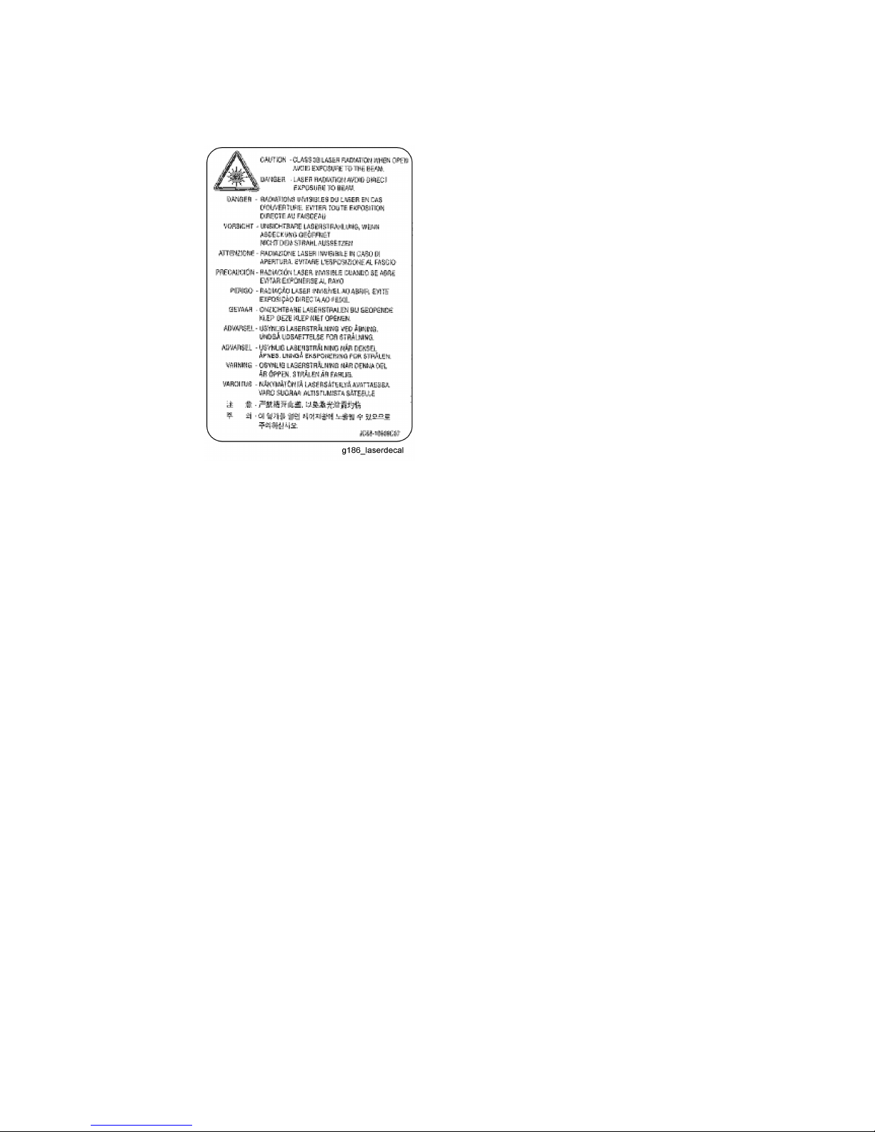
3. Laser Safety Statement
The Printer is certified in the U.S. to conform to the requirements of DHHS 21 CFR,
chapter 1 Subchapter J for Class 1(1) laser products, and elsewhere, it is certified
as a Class I laser product conforming to the requirements of IEC 825. Class I laser
products are not considered to be hazardous. The laser system and printer are
designed so there is never any human access to laser radiation above a Class I
level during normal operation, user maintenance, or prescribed service condition.
Never operate or service the printer with the protective cover removed from
Laser/Scanner assembly. The reflected beam, although invisible, can damage
your eyes. When using this product, these basic safety pre-cautions should always
be followed to reduce risk of fire, electric shock, and injury to persons.
Caution for safety
Toxic material
This product contains toxic materials that could cause illness if ingested.
1. If the LCD control panel is damaged, it is possible for the liquid inside to leak. This
liquid is toxic. Contact with the skin should be avoided, wash any splashes from eyes
or skin immediately and contact your doctor. If the liquid gets into the mouth or is
swallowed, see a doctor immediately.
2. Please keep toner cartridges away from children. The toner powder contained in the
toner cartridge may be harmful and if swallowed, you should contact a doctor.
Electric Shock and Fire Safety Precautions
Failure to follow the following instructions could cause electric shock or potentially cause a
fire.
1. Use only the correct voltage, failure to do so could damage the printer and potentially
cause a fire or electric shock.
2. Use only the power cable supplied with the printer. Use of an incorrectly specified
cable could cause the cable to overheat and potentially cause a fire.
3. Do not overload the power socket, this could lead to overheating of the cables inside
the wall and could lead to a fire.
4. Do not allow water or other liquids to spill into the printer, this can cause electric shock.
Do not allow paper clips, pins or other foreign objects to fall into the printer these could

cause a short circuit leading to an electric shock or fire hazard..
5. Never touch the plugs on either end of the power cable with wet hands, this can cause
electric shock. When servicing the printer remove the power plug from the wall socket.
6. Use caution when inserting or removing the power connector. The power connector
must be inserted completely otherwise a poor contact could cause overheating
possibly leading to a fire. When removing the power connector grip it firmly and pull.
7. Take care of the power cable. Do not allow it to become twisted, bent sharply round
corners or other wise damaged. Do not place objects on top of the power cable. If the
power cable is damaged it could overheat and cause a fire or exposed cables could
cause an electric shock. Replace a damaged power cable immediately, do not reuse or
repair the damaged cable. Some chemicals can attack the coating on the power cable,
weakening the cover or exposing cables causing fire and shock risks.
8. Ensure that the power sockets and plugs are not cracked or broken in any way. Any
such defects should be repaired immediately. Take care not to cut or damage the
power cable or plugs when moving the machine.
9. Use caution during thunder or lightening storms. We recommend that this machine be
disconnected from the power source when such weather conditions are expected. Do
not touch the machine or the power cord if it is still connected to the wall socket in
these weather conditions.
10. Avoid damp or dusty areas, install the printer in a clean well ventilated location. Do not
position the machine near a humidifier. Damp and dust build up inside the machine can
lead to overheating and cause a fire.
11. Do not position the printer in direct sunlight. This will cause the temperature inside the
printer to rise possibly leading to the printer failing to work properly and in extreme
conditions could lead to a fire.
12. Do not insert any metal objects into the machine through the ventilator fan or other part
of the casing, it could make contact with a high voltage conductor inside the machine
and cause an electric shock.
Handling Precautions
The following instructions are for your own personal safety, to avoid injury and so as not to
damage the printer
1. Ensure the printer is installed on a level surface, capable of supporting its weight.
Failure to do so could cause the printer to tip or fall.
2. The printer contains many rollers, gears and fans. Take great care to ensure that you
do not catch your fingers, hair or clothing in any of these rotating devices.

3. Do not place any small metal objects, containers of water, chemicals or other liquids
close to the printer which if spilled could get into the machine and cause damage or a
shock or fire hazard.
4. Do not install the machine in areas with high dust or moisture levels, beside on open
window or close to a humidifier or heater. Damage could be caused to the printer in
such areas.
5. Do not place candles, burning cigarettes, etc on the printer. These could cause a fire.
Assembly/ Disassembly Precautions
Replace parts carefully, always use genuine parts. Take care to note the exact location of
parts and also cable routing before dismantling any part of the machine. Ensure all parts
and cables are replaced correctly.
Please carry out the following procedures before dismantling the printer or replacing any
parts.
(1) Check the contents of the machine memory and make a note of any user settings.
These will be erased if the main board or network card is replaced.
(2) Ensure that power is disconnected before servicing or replacing any electrical parts.
(3) Disconnect printer interface cables and power cables.
(4) Only use approved spare parts. Ensure that part number, product name, any voltage,
current or temperature rating are correct.
(5) When removing or re-fitting any parts do not use excessive force, especially when fitting
screws into plastic.
(6) Take care not to drop any small parts into the machine.
(7) Handling of the OPC Drum
The OPC Drum can be irreparably damaged if it is exposed to light. Take care not to
expose the OPC Drum either to direct sunlight or to fluorescent or incandescent room
lighting. Exposure for as little as five minutes can damage the surface’s
photoconductive properties and will result in print quality degradation. Take extra care
when servicing the printer. Remove the OPC Drum and store it in a black bag or other
lightproof container. Take care when working with the covers (especially the top cover)
open as light is admitted to the OPC area and can damage the OPC Drum.
Take care not to scratch the green surface of OPC Drum Unit. If the green surface of
the Drum Cartridge is scratched or touched the print quality will be compromised.
Disregarding this warning may cause bodily injury
1. Be careful with the high temperature part.
The fuser unit works at a high temperature. Use caution when working on the printer.
Wait for the fuser to cool down before disassembly.
2. Do not put fingers or hair into the rotating parts.
When operating a printer, do not put hand or hair into the rotating parts (Paper feeding
entrance, motor, fan, etc.). If do so, you may get harm.
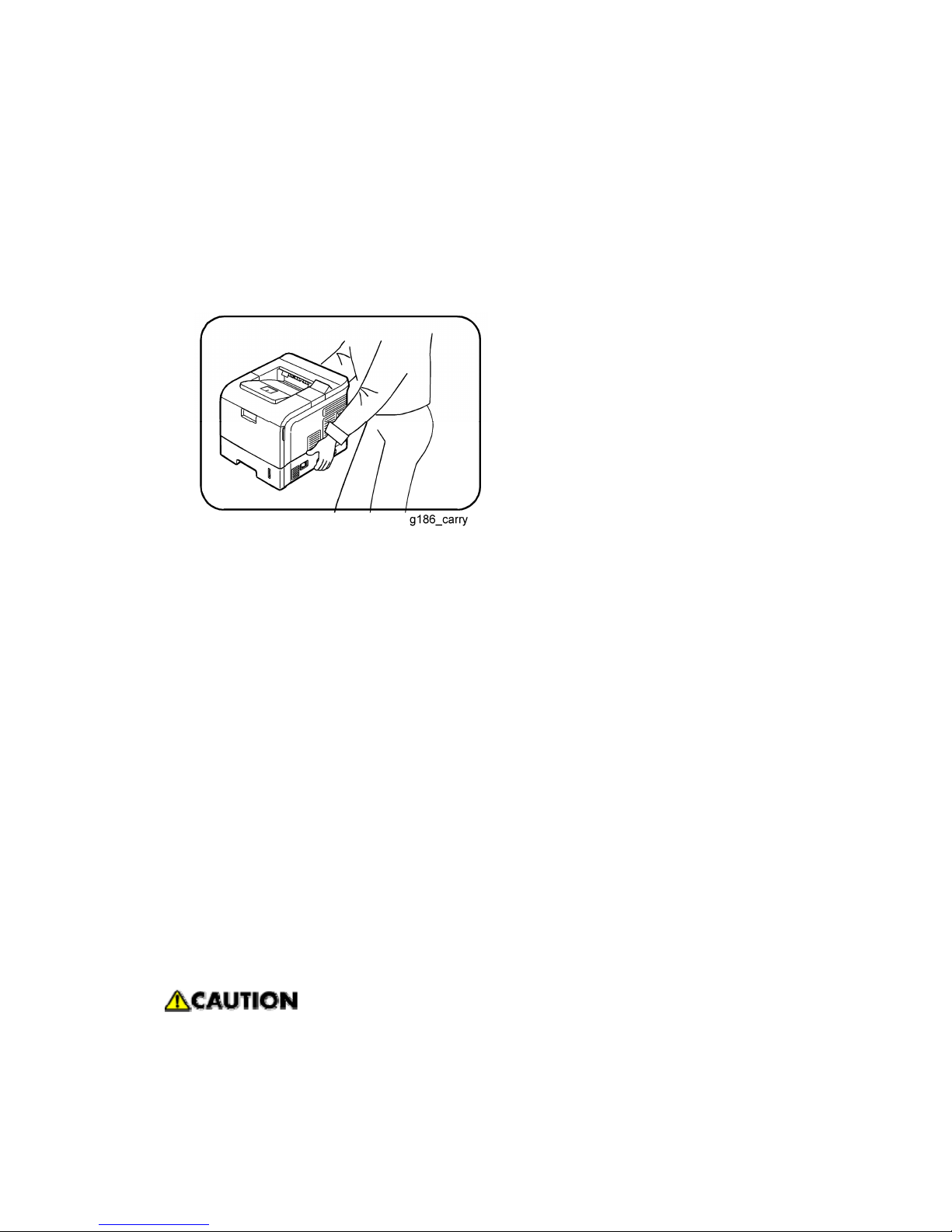
3. When you move the printer.
This printer weighs 17.8kg including the toner cartridge and cassette. Use safe lifting
and handling techniques. Use the lifting handles located on each side of the machine.
Back injury could be caused if you do not lift carefully.
4. Ensure the printer is installed safely.
Ensure the printer is installed on a level surface, capable of supporting its weight.
Failure to do so could cause the printer to tip or fall, possibly causing personal injury or
damaging the printer.
5. Do not install the printer on a sloping or unstable surface.
After installation, double check that the printer is stable.
ESD Precautions
Certain semiconductor devices can be easily damaged by static electricity. Such
components are commonly called “Electrostatically Sensitive (ES) Devices”, or ESDs.
Examples of typical ESDs are: integrated circuits, some field effect transistors, and
semiconductor “chip” components.
The techniques outlined below should be followed to help reduce the incidence of
component damage caused by static electricity.
Be sure that no power is applied to the chassis or circuit, and observe all other
safety precautions.
1. Immediately before handling a semiconductor component or semiconductor-equipped

assembly, drain off any electrostatic charge on your body by touching a known earth
ground. Alternatively, employ a commercially available wrist strap device, which should
be removed for personal safety prior to applying power to the unit under test.
2. After removing an electrical assembly equipped with ESDs, place the assembly on a
conductive surface, such as aluminum or copper foil, or conductive foam, to prevent
electrostatic charge buildup in the vicinity of the assembly.
3. Use only a grounded tip soldering iron to solder or desolder ESDs.
4. Use only an “anti-static” solder removal device. Some solder removal devices not
classified as “anti-static” can generate electrical charges sufficient to damage ESDs.
5. Do not use Freon-propelled chemicals. When sprayed, these can generate electrical
charges sufficient to damage ESDs.
6. Do not remove a replacement ESD from its protective packaging until immediately
before installing it. Most replacement ESDs are packaged with all leads shorted
together by conductive foam, aluminum foil, or a comparable conductive material.
7. Immediately before removing the protective shorting material from the leads of a
replacement ESD, touch the protective material to the chassis or circuit assembly into
which the device will be installed.
8. Maintain continuous electrical contact between the ESD and the assembly into which it
will be installed, until completely plugged or soldered into the circuit.
9. Minimize bodily motions when handling unpackaged replacement ESDs. Normal
motions, such as the brushing together of clothing fabric and lifting one’s foot from a
carpeted floor, can generate static electricity sufficient to damage an ESD.
INSTALLATION
PREVENTIVE MAINTENANCE
REPLACEMENT AND ADJUSTMENT
TROUBLESHOOTING
SERVICE TABLES
DETAILED DESCRIPTIONS
SPECIFICATIONS
APPENDIX
TAB
POSITION 2
TAB
POSITION 1
TAB
POSITION 3
TAB
POSITION 4
TAB
POSITION 6
TAB
POSITION 5
TAB
POSITION 8
TAB
POSITION 7


INSTALLATION


Installation Requirements
SM 1-1 G186
Installation
1. INSTALLATION
1.1 INSTALLATION REQUIREMENTS
Refer to the User's Guide.

 Loading...