

Ricoh G-P2, G161, G160 Service Manual

G160 Service Manual 23-Feb-06
Model G-P2
Machine Code: G160
SERVICE MANUAL
Copyright Ricoh Company, LTD©
Feb. 24th, 2006
Subject to change

G160 Service Manual 23-Feb-06
ii
Read This First
Safety Notices
Important Safety Notices
Prevention of Physical Injury
1. Before disassembling or assembling parts of the printer and peripherals, make
sure that the printer power cord is unplugged.
2. The wall outlet should be near the printer and easily accessible.
3. If any adjustment or operation check has to be made with exterior covers off or
open while the main switch is turned on, keep hands away from electrified or
mechanically driven components.
4. The printer drives some of its components when it completes the warm-up period.
Be careful to keep hands away from the mechanical and electrical components as
the printer starts operation.
5. The inside and the metal parts of the fusing unit become extremely hot while the
printer is operating. Be careful to avoid touching those components with your bare
hands.
Health Safety Conditions
Toner and developer are non-toxic, but if you get either of them in your eyes by accident, it
may cause temporary eye discomfort. Immediately wash eyes with plenty of water. If
unsuccessful, get medical attention.
Observance of Electrical Safety Standards
The printer and its peripherals must be serviced by a customer service representative who
has completed the training course on those models.
Lithium Batteries
Incorrect replacement of lithium battery(s) on the EGB and controller board may pose risk of
explosion. Replace only with the same type or with an equivalent type recommended by the
manufacturer. Discard used batteries in accordance with the manufacturer’s instructions.
G160 Service Manual 23-Feb-06
iii
Safety and Ecological Notes for Disposal
1. Do not incinerate toner bottles or used toner. Toner dust may ignite suddenly when
exposed to an open flame.
2. Dispose of used toner, the maintenance unit which includes developer or the
organic photoconductor in accordance with local regulations. (These are non-toxic
supplies.)
3. Dispose of replaced parts in accordance with local regulations.
4. When keeping used lithium batteries in order to dispose of them later, do not put
more than 100 batteries per sealed box. Storing larger numbers or not sealing
them apart may lead to chemical reactions and heat build-up.
LASER SAFETY
The Center for Devices and Radiological Health (CDRH) prohibits the repair of laser-based
optical units in the field. The optical housing unit can only be repaired in a factory or at a
location with the requisite equipment. The laser subsystem is replaceable in the field by a
qualified Customer Engineer. The laser chassis is not repairable in the field. Customer
engineers are therefore directed to return all chassis and laser subsystems to the factory or
service depot when replacement of the optical subsystem is required.
Use of controls, or adjustment, or performance of procedures other than those
specified in this manual may result in hazardous radiation exposure.
Turn off the main switch before attempting any of the procedures in the Laser Optics Housing
Unit section. Laser beams can seriously damage your eyes.
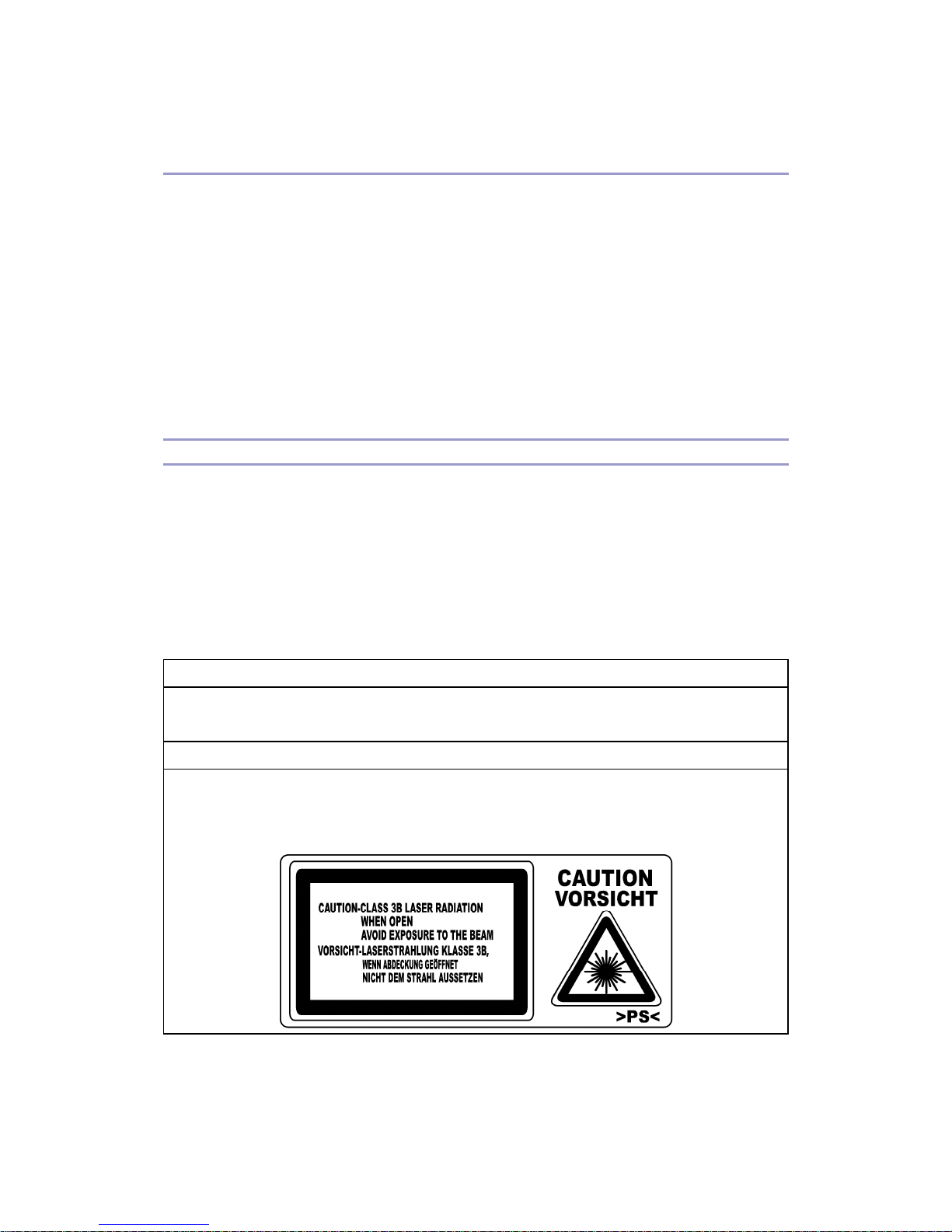
CAUTION MARKING:

G160 Service Manual 23-Feb-06
iv
Symbols, Abbreviations, and Trademarks
Symbols and Abbreviations
This manual uses the symbols and abbreviations shown below.
Symbol Meaning
Refer to section number
Clip ring
Screw
Connector
Clamp
SEF Short Edge Feed
LEF Long Edge Feed
Trademarks
Microsoft®, Windows®, and MS-DOS® are registered trademarks of Microsoft Corporation
in the United States and /or other countries.
PostScript® is a registered trademark of Adobe Systems, Incorporated.
PCL® is a registered trademark of Hewlett-Packard Company.
Ethernet® is a registered trademark of Xerox Corporation.
PowerPC® is a registered trademark of International Business Machines Corporation.
Other product names used herein are for identification purposes only and may be trademarks
of their respective companies. We disclaim any and all rights involved with those marks.

G160 Service Manual 23-Feb-06
v
Table of Contents
Read This First ..................................................................................................................... ii
Safety Notices................................................................................................................... ii
Important Safety Notices ...............................................................................................
ii
LASER SAFETY............................................................................................................
iii
Symbols, Abbreviations, and Trademarks ........................................................................
iv
Symbols and Abbreviations ..........................................................................................
iv
Trademarks...................................................................................................................
iv
Table of Contents..................................................................................................................
v
Installation Procedure ...........................................................................................................1
Installation Requirements..................................................................................................1
Optional Unit Installation ...................................................................................................
2
Preventive Maintenance .......................................................................................................
3
User Replaceable Items.................................................................................................... 3
Service Maintenance.........................................................................................................
4
Recommended Cleaning Procedure..............................................................................
4
Replacement And Adjustment...............................................................................................
5
Before You Start ................................................................................................................ 5
Laser Optics ......................................................................................................................
6
Caution Decal Locations................................................................................................
6
LD Unit...........................................................................................................................
7
Fusing .............................................................................................................................
10
Thermistor and Thermostat .........................................................................................
10
Electrical Components ....................................................................................................
13
Controller Board ..........................................................................................................
13
Installing the new NVRAM ...........................................................................................
14
Troubleshooting ..................................................................................................................
15
Process Control Results.................................................................................................. 15
Service Call Conditions ...................................................................................................
17
Summary .....................................................................................................................
17
SC Code Descriptions .................................................................................................
17
Troubleshooting Guide....................................................................................................
46
Blank Print ...................................................................................................................
46
All-black Print...............................................................................................................
46
Missing CMY Color......................................................................................................
46

G160 Service Manual 23-Feb-06
vi
Light Print ....................................................................................................................47
Repeated Spots or Lines on Prints ..............................................................................
47
Dark Vertical Line on Prints .........................................................................................
48
White Horizontal Lines or Bands .................................................................................
48
Missing Parts of Images ..............................................................................................
49
Dirty Background .........................................................................................................
49
Partial CMY Color Dots................................................................................................
49
Dark Irregular Streaks on Prints...................................................................................
49
CMY Color Irregular Streaks........................................................................................
50
Ghosting ......................................................................................................................
50
Unfused or Partially Fused Prints ................................................................................
50
Image Skew.................................................................................................................
51
Background Stain ........................................................................................................
51
No Printing on Paper Edge..........................................................................................
51
Image not centered when it should be.........................................................................
52
Electrical Component Defects .........................................................................................
53
Sensors .......................................................................................................................
53
Blown Fuse Conditions ...................................................................................................
57
Power Supply Unit .......................................................................................................
57
IOB ..............................................................................................................................
57
LEDs ...............................................................................................................................
58
Controller .....................................................................................................................
58
Service Tables ....................................................................................................................
59
Service Program Mode ...................................................................................................59
Service Mode Operation..............................................................................................
59
Remarks ......................................................................................................................
60
Bit Switch Programming ..............................................................................................
62
Service Mode Table.........................................................................................................
64
Controller Service Mode ..............................................................................................
64
Engine Service Mode ..................................................................................................
68
Input Check Table......................................................................................................
216
Output Check Table ...................................................................................................
220
Firmware Update...........................................................................................................
223
Types of Firmware.....................................................................................................
223
Precautions................................................................................................................
223
SD Card Application Move ............................................................................................
224

G160 Service Manual 23-Feb-06
vii
Overview....................................................................................................................224
Move Exec.................................................................................................................
224
Undo Exec .................................................................................................................
225
Keeping the SD Card.................................................................................................
226
Detailed Section Descriptions...........................................................................................
227
Beforehand.................................................................................................................... 227
Overview .......................................................................................................................
228
Component Layout ....................................................................................................
228
Board Structure..........................................................................................................
229
Process Control.............................................................................................................
232
Overview....................................................................................................................
232
Potential Control ........................................................................................................
232
Toner Supply Control .................................................................................................
235
Toner Near End/Toner End Detection ........................................................................
237
Developer Initialization...............................................................................................
238
Paper Feed ...................................................................................................................
239
By-pass Tray Feed and Size Detection......................................................................
239
Laser Exposure .............................................................................................................
240
LD Safety Switch .......................................................................................................
240
Automatic Line Position Adjustment ..........................................................................
241
Fusing ...........................................................................................................................
245
Overview....................................................................................................................
245
Fusing Temperature Control ......................................................................................
246
Drive ..........................................................................................................................
249
Controller.......................................................................................................................
250
Overview....................................................................................................................
250
Board Layout .............................................................................................................
252
Specifications....................................................................................................................
253
Specifications ................................................................................................................ 253
General Specifications...............................................................................................
253
Supported Paper Sizes..............................................................................................
256
Software Accessories ................................................................................................
257
Machine Configuration...............................................................................................
259

G160 Service Manual 23-Feb-06
1
Installation Procedure
Installation Requirements
The installation procedure for G-P2 (G160/G161) is the same as G-P1 (G104/G105). For
details, refer to the Quick Installation Guide for G-P2 (G160/G161).

G160 Service Manual 23-Feb-06
2
Optional Unit Installation
The following options are available for this machine. Refer to the Hardware Guide for how to
install these options:
Paper Tray Unit (G392)
HDD (G395)
IEEE802.11b Interface Unit (Wireless LAN: G813)
IEEE 1284 Interface Board (B679)
Bluetooth Interface Unit (B826)
Gigabit Ethernet Board (G874-01)
VM Card (G874-08)
USB Host Interface Unit (B825)
Data Overwrite Security Unit (G874-21)
PictBridge Interface (G874-19)
128 MB DIMM (B584)
256 MB DIMM (G818)
NVRAM (User account enhancement: G395)

G160 Service Manual 23-Feb-06
3
Preventive Maintenance
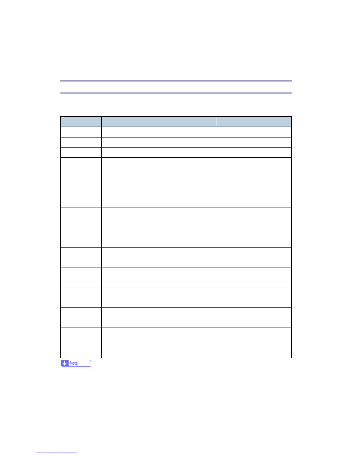
User Replaceable Items
The user replaces the following items if the service contract requires that the user does some
of the PM.
Item Remarks
PCU 50 KP (YMC, BK)
Transfer Belt Unit 100 KP
Waste Toner Bottle 50 KP
Maintenance Kit
Fusing Unit
Transfer Roller
Paper Feed Roller x 3
Friction Pad x 3
Dust Filter x 2
100 KP
Chart: A4 (LT), 5%
Mode: Continuously Printing
Environment: Recommended temperature and humidity
Yield changes depend on circumstances and print conditions
An error message shows when a maintenance counter gets to the value in the PM table when
the machine’s default settings are used.
It is not necessary to reset counters for each part if the technician does the PM. The machine
detects new components automatically and resets the necessary counters.

G160 Service Manual 23-Feb-06
4
Service Maintenance
Recommended Cleaning Procedure
1. Turn off the main switch.
2. Remove the waste toner bottle.
3. Remove the PCUs.
4. Remove the transfer belt unit. Do not touch the transfer belt surface.
5. Remove the fusing unit.
6. Remove the standard paper tray.
7. Clean the paper path.
8. Clean all printer rollers with dry cloth only.
Do not clean the transfer roller.
9. Use a blower brush to clean the laser unit windows.
10. Vacuum the interior of the printer.
11. Carefully clean the area around the transfer roller.
G160 Service Manual 23-Feb-06
5
Replacement And Adjustment
Before You Start
This section shows the differences between G-P1 (G104/G105) and G-P2 (G160/G161). For
other items procedures, refer to the service manual for G-P1 (G104/G105).
Turn off the main power switch and unplug the machine before you do the
procedures in this section.
Remove these before you do a removal procedure:
4 toner bottles (cyan, magenta, yellow, and black)
Waste toner bottle
Standard paper tray
G160 Service Manual 23-Feb-06
6
Laser Optics
Turn off the main power switch and unplug the printer before you do the procedures
in this section. Laser beams can cause serious eye injury.
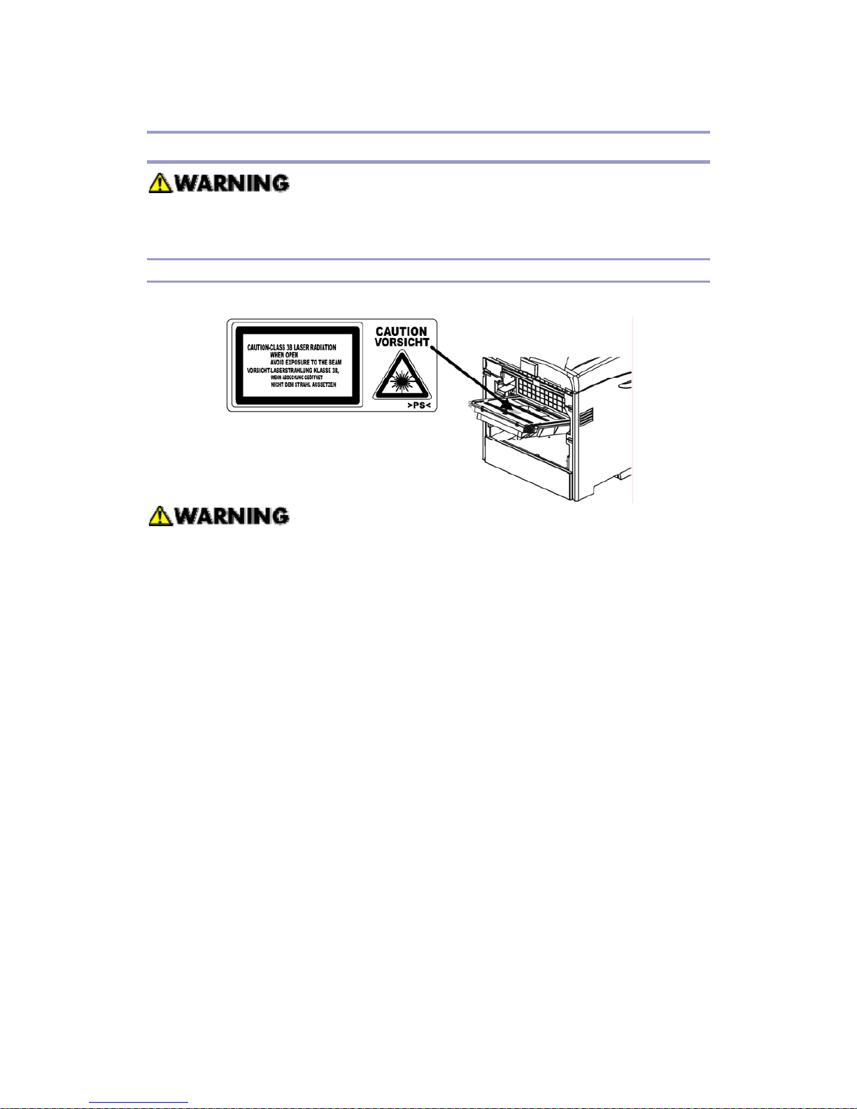
Caution Decal Locations
The caution decal is attached as shown below
Make sure to turn off the main power switch and disconnect the power plug from the
power outlet before you do any disassembly or adjustment of the laser unit. This
printer uses a class 3B laser beam with a wavelength of 655 nm and an output of 7
mW. The laser can cause serious eye injury.
G160 Service Manual 23-Feb-06
7
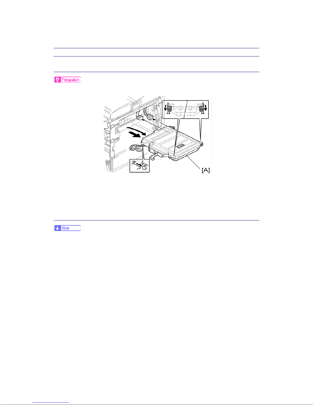
LD Unit
Replacement
Print the SMC report with SP 5990 2 before you replace the LDU.
1. Electrical board unit (see the Service Manual for G-P1 (G104/G105): ‘Electrical
Components – Electrical Board Unit’)
2. LDU [A]
Color Registration Adjustment
You must manually do the color registration adjustment after you install the new
LDU.
When the polygon mirror motor or LDB unit is defective, only replace the defective
parts. At this time, if only the motor is changed it is not necessary to do this
adjustment procedure.
1. Print the SMC report with SP 5990 2 before you replace the LDU. Find the values
for SP 2181 1, SP 2181 11, 2181 21, and 2181 31.
2. Do SP 2111 2 (Pro. Position Adj > Execute) to roughly adjust the line position after
you install the new LDU. “Result = OK” shows on the LCD if this is done correctly .
If not, do it again until you get “OK”.
3. Do SP2111 3 (Skew Adjust. > Execute) to measure the skew values for each color.
“Result = OK” shows on the LCD if this is done correctly. If not, do it again until
you get “OK”.
4. Check the skew values with SP 2181: Then write down the values. (You can also
check these if you print the SMC report again with SP 5990 2. The values will

G160 Service Manual 23-Feb-06
8
probably be different from the values on the report that you printed in step 1.)
SP 2181 1 for black skew
SP 2181 11 for magenta
SP 2181 21 for cyan
SP 2181 31 for yellow
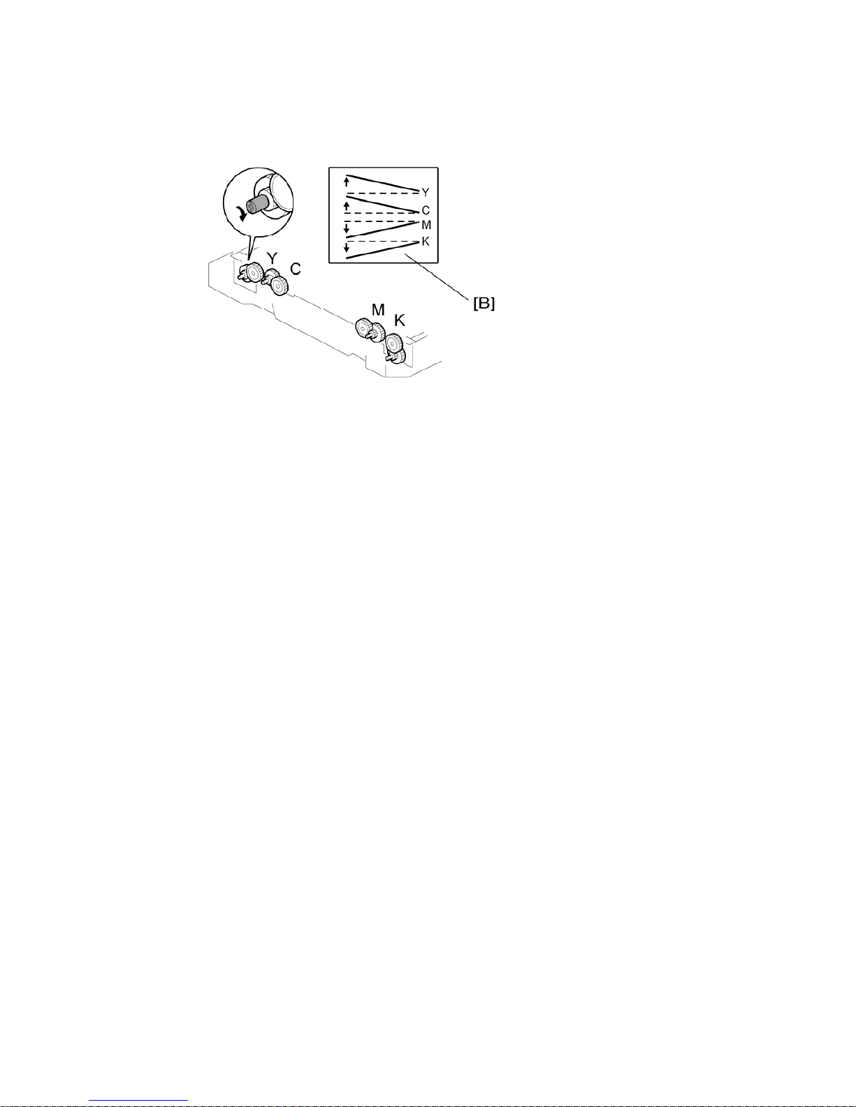
5. Open the left cover
6. Adjust the skew adjustment cam [A] for each color with a screwdriver. You must
adjust the skew values for each color until they are all the same as the value for
magenta that you found in step 1, before you replaced the LDU.
For example: If the new value for K (after step 4) is –300 and the old value for
magenta (in step 1) is –250, you must adjust the skew for K until it is –250.
Turn the cam as shown in the “Cam Rotation Direction” column below to increase
the skew value.
Turn it in the opposite direction from this to decrease the skew value.
“Adjustment value” shows the change when you turn the cam one click.
Color
Cam Rotation
Direction
Adjustment
Value
Yellow CW 14 μm
Cyan CW 10 μm
Magenta CCW 10 μm
Black CCW 10 μm
The adjustment values in the table are not exact values. These are
approximate values.
G160 Service Manual 23-Feb-06
9
CW: Clockwise, CCW: Counter-clockwise
The diagram shows the effect on line skew [B] when you turn the cam in a
counter clockwise direction.
7. Close the left cover. Then measure the skew values again with SP 2111 3. (To do
this, repeat step 3.)
If these are close to the value for magenta that you found in step 1 (within one click in
the above table), go to the next step. If not, do SP 2111 3 again until you get a good
result.
8. Do SP 2111 1 to finely adjust the line position for each color.
Try SP 2111 2 if “Result = OK” does not show.
9. When you get “Result = OK”, this adjustment is completed.

G160 Service Manual 23-Feb-06
10
Fusing
Make sure that the fusing unit is cool before you touch it. The fusing unit can
be very hot.
Make sure to restore the insulators, shields, etc after you service the fusing
unit.
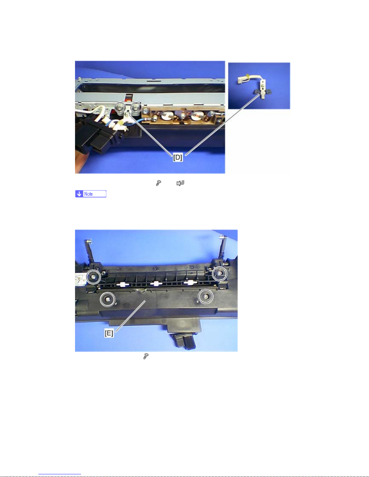
Thermistor and Thermostat
1. Front door
2. Fusing unit (see the Service Manual for G-P1 (G105/G16): ‘Fusing Unit’)
3. Fusing unit guide plate [A] (
x 4)
4. Release the connector [B] from the fusing lower cover [C] (hook x 1).
5. Fusing lower cover [C] (
x 2)
G160 Service Manual 23-Feb-06
11
6. Thermistor with bracket [D] (
x 2, x 1)
Do not remove the thermistor from the bracket when removing it. The pressure
of the thermistor plate to the fusing belt is adjusted properly in the factory. If you
remove it, some image problem may occur.
7. Fusing upper cover [E] (
x 4)
G160 Service Manual 23-Feb-06
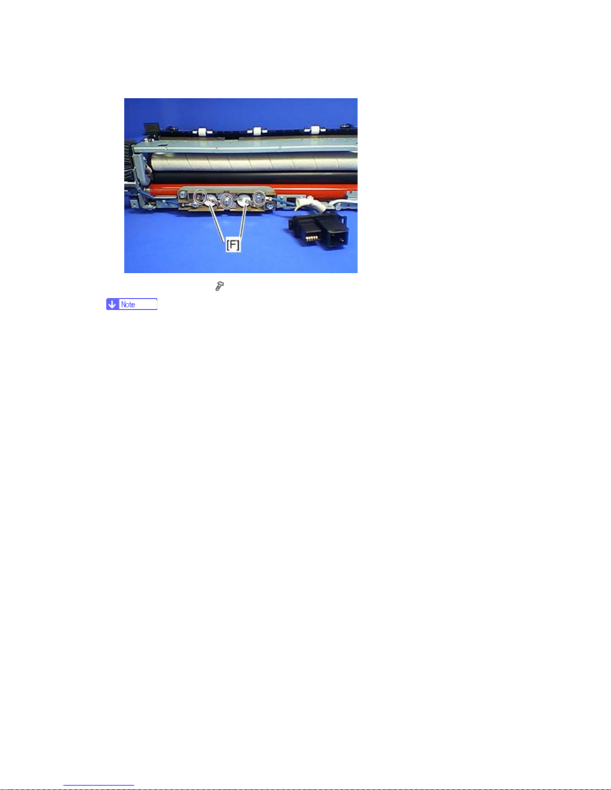
12
8. Thermostat [F] x 2 (
x 3)
Do not recycle a thermostat that is already opened. Safety is not guaranteed if you
do this.
G160 Service Manual 23-Feb-06
13
Electrical Components
Before you replace the EGB (Engine Board), the controller, or the NVRAM, print
out the SMC reports (“SP Mode Data” and “Logging Data”).
After you replace the EGB (Engine Board) or the controller, remove the NVRAM
from the old board and install it on the new board. If the NVRAM on the old
board is defective, replace the NVRAM (see ‘NVRAM Replacement
Procedure’).
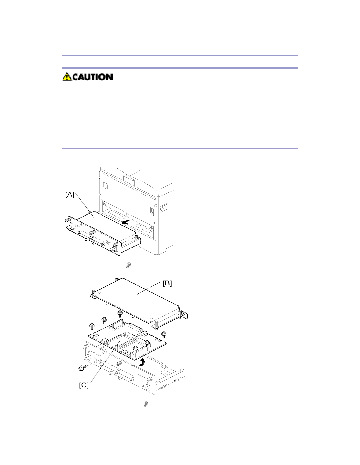
Controller Board
1. Controller unit [A] (
x 3)
2. Controller unit cover [B] (
x 4)
G160 Service Manual 23-Feb-06
14
3. Controller board [C] (
x 7)
Remove the NVRAM from the old board. Then install it on the new board.
Keep NVRAMs away from objects that can cause static electricity. The data in
NVRAMs can be corrupted by static electricity.
Make sure the NVRAM is correctly installed on the board. A half-disk is
engraved on one side of the NVRAM, and a guide mark is on one side of the
NVRAM slot. When you install the NVRAM, the half-disk and the guide mark
must be on the same side.
Installing the new NVRAM
When the NVRAM on the controller board is detective, you must replace the detective
NVRAM to new NVRAM.
1. Controller board (see Controller Board)
2. Remove the defective NVRAM.
3. Install the new NVRAM on the controller board.
4. Reassemble the machine.
5. Plug in and turn on the main power
6. Set the date and time with the timer setting in the UP (Maintenance < Menu ) after
installing a new controller board.
If the date and time setting is not done, the WebImage Moniter can not be available.
G160 Service Manual 23-Feb-06
15
Troubleshooting
Process Control Results
The table below lists the process control results shown in SP 3821.
Number Result Notes
10 Success No error
21 ID sensor correction error SC 400
22 ID sensor: LED adjustment error SC 418
31 Charge bias correction error SC 300 to 307
51 High Vmin (Bk), High K2 (Color) error
SP 3145 (see the note below
the table)
52 Low K2 (Color) error
SP 3146 (see the note below
the table)
53 High K5 error
SP 3147 (see the note below
the table)
54 Low K5 error
SP 3147 (see the note below
the table)
55 High development gamma
Gamma > 5.0 (see the note
below the table)
56 Low development gamma
Gamma < 0.5 (see the note
below the table)
57 Development bias adjustment error
Vk >150V (see the note
below the table)
58 Development bias adjustment error
Vk < -150V (see the note
below the table)
90 No process control -
99 Not successful
Interrupt during the process
control (e.g. Door open)
This error code does not usually occur. If no problem is observed with image density
and/or development gamma, nothing needs to be done. If an image problem such as
low image density is observed, check the following points: Transfer belt/PCU/ID
sensor/Toner bottle

G160 Service Manual 23-Feb-06
16
The 8 numbers on the LCD in SP 3821 indicate the process control result for each color.
There are two numbers for each color. The numbers are shown from left to right on the
display as follows: Black, Magenta, Cyan, Yellow. For example, if process control for each
color is successful: 10 (Black), 10 (Magenta), 10 (Cyan), 10 (Yellow)
G160 Service Manual 23-Feb-06
17
Service Call Conditions
Summary
1. All SCs are logged.
2. First disconnect then reconnect the connectors before you replace the PCBs if the
problem concerns electrical circuit boards.
3. First check the mechanical load before you replace motors or sensors if the
problem concerns a motor lock.
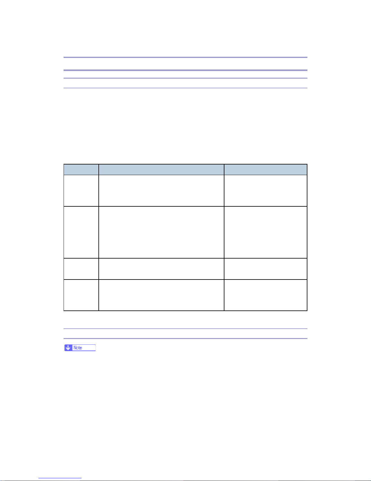
There are 4 levels of service call conditions.
Level Definition Reset Procedure
A
To prevent damage to the machine, the main
machine cannot be operated until a service
representative has reset the SC.
Do SP 5810, and then turn the
main power switch off and on.
B
SCs that disable only the features that use the
defective item. Although these SCs are not
shown to the user under normal conditions,
they are displayed on the operation panel only
when the defective feature is selected.
Turn the operation switch or
main switch off and on.
C
The SC history is updated. The machine can be
operated as usual.
The SC will not be displayed.
Only the SC history is updated.
D
Turning the main switch off then on resets SCs
displayed on the operation panel. These are
redisplayed if the error occurs again.
Turn the operation switch off
and on.
SC Code Descriptions
Remove the NVRAM from the old board and install it on the new one when you
replace the EGB or the controller board.
The SC level is indicated under SC number in the list below.
The numbers (1, etc.) in the “Possible Cause/Requirement Action” column indicate the
required actions.
G160 Service Manual 23-Feb-06
18
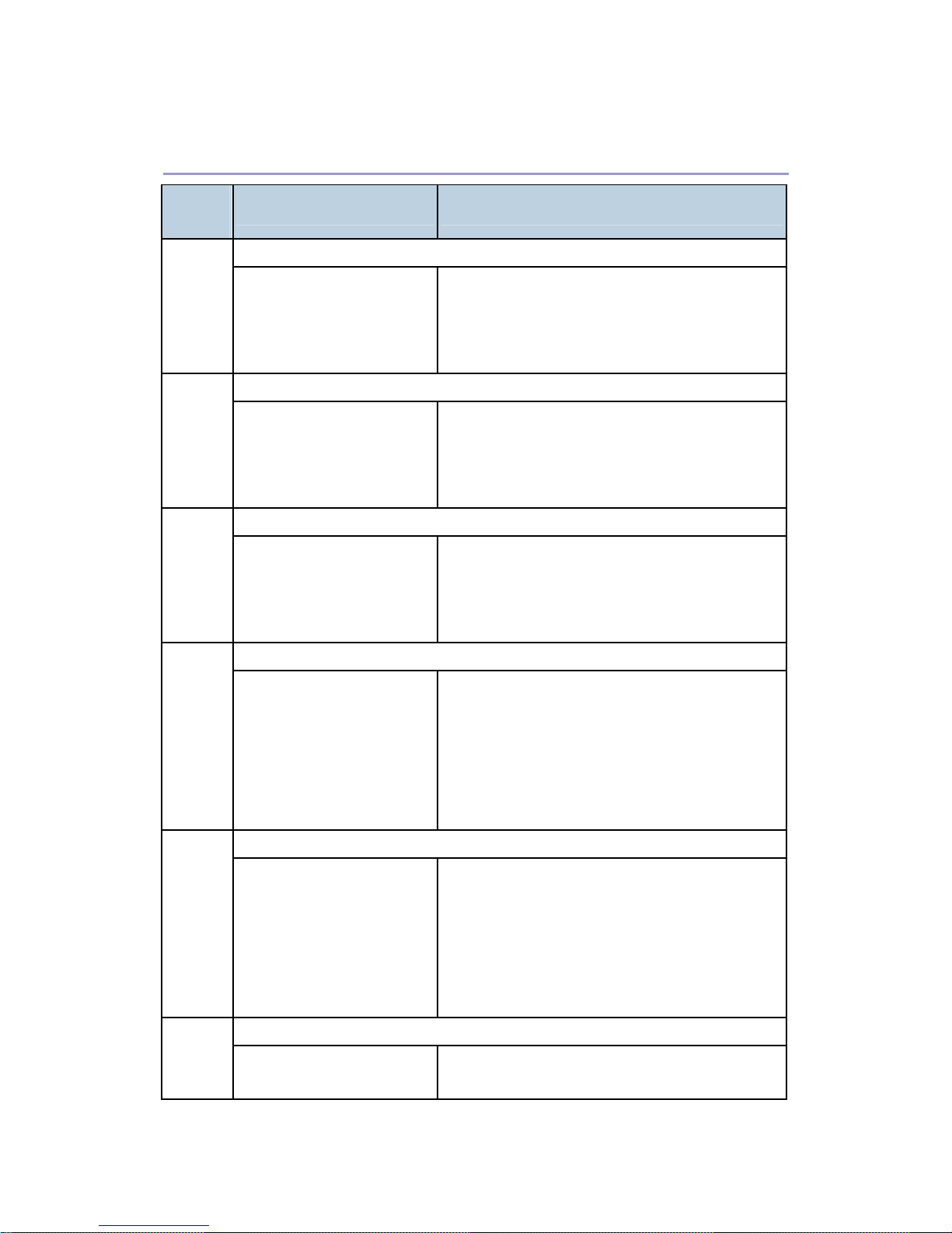
Engine SC
SC
[Level]
Symptom Possible Cause/Required Action
Incorrect serial number
195
[D]
When checking the
registered product number, it
does not match the printer’s
product number.
Registered product number does not match
the printer’s product number.
1. Ask your service key man.
Polygon motor error: Time out with the polygon motor activated
202
[D]
After the polygon motor turns
on or changes the speed,
SCRDY_N is not active
within 10 seconds.
Disconnected cable from the polygon motor
drive board or defective connection
Defective polygon motor or drive board
Polygon motor error: Time out with the polygon motor inactivated
203
[C]
After the polygon motor turns
off or changes the speed,
SCRDY_N is not inactive
within 10 seconds.
Disconnected cable from the polygon motor
drive board or defective connection
Defective polygon motor or drive board
Polygon motor error: XSCRDY signal error
204
[C]
PMRDY_N signal
consecutively detects that
the polygon motor is an
inactive state while LDB unit
scans.
Disconnected cable from the polygon motor
drive board or defective connection
Defective polygon motor or drive board
1. Check the connectors.
2. Replace the polygon motor.
3. Replace the polygon motor drive board.
Polygon motor error: XSCRDY signal not stable
205
[D]
PMRDY_N signal
consecutively detects that
the polygon motor is an
inactive state while the
polygon motor turns on or
changes the speed.
Disconnected cable from the polygon motor
drive board or defective connection
Defective polygon motor or drive board.
1. Check the connectors.
2. Replace the polygon motor.
3. Replace the polygon motor drive board.
Trailing edge laser detection error: [K]
210
[C]
The laser synchronizing
detection signal for LDB [K]
Disconnected cable from the laser
synchronizing detection unit or defective

G160 Service Manual 23-Feb-06
19
SC
[Level]
Symptom Possible Cause/Required Action
of the trailing edge is not
detected for one second after
the LDB unit turned on when
detecting the main scan
magnification.
connection
Defective laser synchronizing detector
Defective LDB
Defective EGB
1. Check the connectors.
2. Replace the laser-synchronizing
detector.
3. Replace the LDB.
4. Replace the EGB.
Trailing edge laser detection error: [Y]
211
[C]
The laser synchronizing
detection signal for LDB [Y]
of the trailing edge is not
detected for one second after
the LDB unit turned on when
detecting the main scan
magnification.
Same as SC 210
Trailing edge laser detection error: [M]
212
[C]
The laser synchronizing
detection signal for LDB [M]
of the trailing edge is not
detected for one second after
the LDB unit turned on when
detecting the main scan
magnification.
Same as SC 210
Trailing edge laser detection error: [C]
213
[C]
The laser synchronizing
detection signal for LDB [C]
of the trailing edge is not
detected for one second after
the LDB unit turned on when
detecting the main scan
magnification.
Same as SC 210

G160 Service Manual 23-Feb-06
20
SC
[Level]
Symptom Possible Cause/Required Action
Laser Synchronizing Detection Error: LDB of the leading edge [K]
220
[D]
The laser synchronizing
detection signal for LDB [K]
of the leading edge is not
output for two seconds after
LDB unit turns on while the
polygon motor is rotating
normally.
Disconnected cable from the laser
synchronizing detection unit or defective
connection
Defective laser synchronizing detector
Defective LDB
Defective EGB
1. Check the connectors.
2. Replace the laser-synchronizing
detector.
3. Replace the LDB.
4. Replace the EGB.
Leading edge laser detection error: [Y]
222
[D]
The laser synchronizing
detection signal for LDB [Y]
of the leading edge is not
output for two seconds after
LDB unit turns on while the
polygon motor is rotating
normally.
Same as SC 221
Leading edge laser detection error: [M]
224
[D]
The laser synchronizing
detection signal for LDB [M]
of the leading edge is not
output for two seconds after
LDB unit turns on while the
polygon motor is rotating
normally.
Same as SC 221
Leading edge laser detection error: [C]
226
[D]
The laser synchronizing
detection signal for LDB [C]
of the leading edge is not
output for two seconds after
Same as SC 221
G160 Service Manual 23-Feb-06
21
SC
[Level]
Symptom Possible Cause/Required Action
LDB unit turns on while the
polygon motor is rotating
normally.
FGATE: On error [K]
230
[C]
The PFGATE ON signal does
not assert within 5 seconds
after processing the image in
normal job or MUSIC for [K]
starts.
Defective connection between the controller
board and EGB
Defective cable between the EGB and LDB
1. Check the connectors.
2. Replace the LDB.
3. Replace the EGB.
FGATE: Off error [K]
231
[C]
The PFGATE ON signal
still asserts within 5
seconds after processing
the image in normal job
or MUSIC for [K] ends.
The PFGATE ON signal
still asserts when the
next job starts.
Defective connection between the controller
board and EGB
Defective cable between the EGB and LDB
1. Check the connectors.
2. Replace the LDB.
3. Replace the EGB.
FGATE: On error [Y]
232
[C]
The PFGATE register of
GAVD does not assert within
5 seconds after processing
the image in normal job or
MUSIC for [Y] started.
Same as SC 230
FGATE: Off error [Y]
233
[C]
The PFGATE ON signal
still asserts within 5
seconds after processing
the image in normal job
or MUSIC for [K] ends.
The PFGATE ON signal
still asserts when the
Same as SC 231
G160 Service Manual 23-Feb-06
22
SC
[Level]
Symptom Possible Cause/Required Action
next job starts.
FGATE: On error [M]
234
[C]
The PFGATE register of
GAVD does not assert within
5 seconds after processing
the image in normal job or
MUSIC for [M] started.
Same as SC 230
FGATE: Off error [M]
235
[C]
The PFGATE ON signal
still asserts within 5
seconds after processing
the image in normal job
or MUSIC for [M] ends.
The PFGATE ON signal
still asserts when the
next job starts.
Same as SC 231
FGATE: On error [C]
236
[C]
The PFGATE register of
GAVD does not assert within
5 seconds after processing
the image in normal job or
MUSIC for [C] started.
Same as SC 230
FGATE: Off error [C]
237
[C]
The PFGATE ON signal
still asserts within 5
seconds after processing
the image in normal job
or MUSIC for [C] ends.
The PFGATE ON signal
still asserts when the
next job starts.
Same as SC 231
LDB error [K] 240
[D]
The EGB detects LDB error a Defective LDB
G160 Service Manual 23-Feb-06
23
SC
[Level]
Symptom Possible Cause/Required Action
few times consecutively
when LDB unit turns on after
LDB initialization.
1. Replace the LDB.
LDB error [Y]
241
[D]
The EGB detects LDB error a
few times consecutively
when LDB unit turns on after
LDB initialization.
Same as SC240
LDB error [M]
242
[D]
The EGB detects LDB error a
few times consecutively
when LDB unit turns on after
LDB initialization.
Same as SC240
LDB error [C]
243
[D]
The EGB detects LDB error a
few times consecutively
when LDB unit turns on after
LDB initialization.
Same as SC240
LDU shutter error
270
[D]
Sensor output does not
change even if 1 second
passes after the LDU shutter
motor is on.
Sensor defective or LDU shutter motor
defective
1. Replace the LDU shutter sensor or
shutter motor.
High voltage power board: Charge voltage output error [K]
300
[D]
The measured voltage is not
proper when EGB measures
the charge output for each
color.
Defective charge roller
Defective connectors
Disconnected harness
Defective high voltage power 1
1. Check the connectors.
2. Replace the PCU for black.
3. Replace the drum positioning plate.
4. Replace the high voltage power 1.
301 High voltage power board: Charge voltage output error [M]
 Loading...