

Ricoh G147 Service Manual

G147
SERVICE MANUAL
002813MIU


G147
SERVICE MANUAL


G147
SERVICE MANUAL
002813MIU


It is the reader's responsibility when discussing the information contained
within this document to maintain a level of confidentiality that is in the best
interest of Ricoh Corporation and its member companies.
NO PART OF THIS DOCUMENT MAY BE REPRODUCED IN ANY
FASHION AND DISTRIBUTED WITHOUT THE PRIOR
PERMISSION OF RICOH CORPORATION.
All product names, domain names or product illustrations, including
desktop images, used in this document are trademarks, registered
trademarks or the property of their respective companies.
They are used throughout this book in an informational or editorial fashion
only and for the benefit of such companies. No such use, or the use of
any trade name, or web site is intended to convey endorsement or other
affiliation with Ricoh products.
© 2006 RICOH Corporation. All rights reserved.


The Service Manual contains information
regarding service techniques, procedures,
processes and spare parts of office equipment
distributed by Ricoh Corporation. Users of this
manual should be either service trained or
certified by successfully completing a Ricoh
Technical Training Program.
Untrained and uncertified users utilizing
information contained in this service manual to
repair or modify Ricoh equipment risk personal
injury, damage to property or loss of warranty
protection.
Ricoh Corporation
WARNING


LEGEND
PRODUCT CODE COMPANY
GESTETNER LANIER RICOH SAVIN
G147 P7245 LP145n Aficio SP 8100DN MLP145
DOCUMENTATION HISTORY
REV. NO. DATE COMMENTS
*
09/2006 Original Printing


SM i G147
G147
TABLE OF CONTENTS
INSTALLATION
1. INSTALLATION ....................................................................... 1-1
1.1 CAUTIONS ............................................................................................1-1
1.2 INSTALLATION REQUIREMENTS .......................................................1-2
1.2.1 ENVIRONMENT...........................................................................1-2
1.2.2 MACHINE LEVEL.........................................................................1-2
1.2.3 MINIMUM SPACE REQUIREMENTS ..........................................1-2
1.2.4 POWER REQUIREMENTS ..........................................................1-3
1.3 MAIN MACHINE INSTALLATION..........................................................1-4
1.3.1 INSTALLATION OVERVIEW........................................................1-4
1.3.2 INSTALLATION FLOWCHART ....................................................1-5
1.4 LCT (B543) ............................................................................................1-6
1.4.1 ACCESSORY CHECK: LCT.........................................................1-6
1.4.2 INSTALLATION PROCEDURE: LCT ...........................................1-6
1.5 BRIDGE UNIT (B538)............................................................................1-9
1.5.1 ACCESSORY CHECK: BRIDGE UNIT ........................................1-9
1.5.2 INSTALLATION PROCEDURE: BRIDGE UNIT ...........................1-9
1.6 TWO-TRAY FINISHER (G838)............................................................1-13
1.6.1 ACCESSORY CHECK: TWO TRAY FINISHER.........................1-13
1.6.2 INSTALLATION PROCEDURE: TWO-TRAY FINISHER ...........1-13
1.7 PUNCH UNIT (B377)...........................................................................1-17
1.7.1 ACCESSORY CHECK: PUNCH UNIT .......................................1-17
1.7.2 INSTALLATION PROCEDURE: PUNCH UNIT ..........................1-17
1.8 DATA OVERWRITE SECURITY UNIT (B735) ....................................1-21
1.8.1 BEFORE YOU BEGIN… ............................................................1-21
1.8.2
SEAL CHECK AND REMOVAL..................................................1-21
1.8.3 INSTALLATION PROCEDURE: DOS UNIT ...............................1-22
1.9 CONTROLLER OPTIONS ...................................................................1-24
1.9.1 BOARDS AND SLOTS ...............................................................1-24
1.9.2 INSTALLING SD CARDS ...........................................................1-25
1.9.3 MERGING APPLICATIONS ON ONE SD CARD.......................1-26
1.9.4 INSTALLING CONTROLLER OPTIONS ....................................1-28
PREVENTIVE MAINTENANCE
2. PREVENTIVE MAINTENANCE ............................................... 2-1
2.1 PM TABLES ..........................................................................................2-1
2.1.1 PM TABLES FOR THE PRINTER................................................2-1
2.1.2 PM TABLES FOR OPTIONS........................................................2-4

G147 ii SM
2.2 LUBRICATION ......................................................................................2-6
REPLACEMENT AND ADJUSTMENT
3. REPLACEMENT AND ADJUSTMENT.................................... 3-1
3.1 PRECAUTIONS.....................................................................................3-1
3.1.1 GENERAL PRECAUTIONS .........................................................3-1
3.1.2 LASER UNIT PRECAUTIONS .....................................................3-1
3.2 SPECIAL TOOLS AND LUBRICANTS ..................................................3-2
3.2.1 SPECIAL TOOLS .........................................................................3-2
3.2.2 LUBRICANTS...............................................................................3-2
3.3 COVERS AND COMMON PROCEDURES ...........................................3-3
3.3.1 FRONT DOOR .............................................................................3-3
3.3.2 DUPLEX UNIT..............................................................................3-3
3.3.3 RIGHT UPPER COVER ...............................................................3-4
3.3.4 BY-PASS TRAY UNIT..................................................................3-5
3.3.5 REAR COVERS ...........................................................................3-5
3.3.6 LEFT COVERS.............................................................................3-6
3.4 OPERATION PANEL.............................................................................3-7
3.5 PAPER OUTPUT TRAY ........................................................................3-8
3.6 LASER UNIT .......................................................................................3-10
3.6.1 CAUTION DECAL LOCATIONS.................................................3-10
3.6.2 LASER UNIT REMOVAL............................................................3-10
3.6.3 POLYGON MIRROR MOTOR....................................................3-12
3.6.4 LASER SYNCHRONIZATION DETECTOR ...............................3-13
3.6.5 LD UNIT .....................................................................................3-13
3.7 PCDU ..................................................................................................3-16
3.7.1 PHOTOCONDUCTOR CLEANING/DEVELOPMENT UNIT.......3-16
3.7.2 DRUM.........................................................................................3-17
3.7.3 PICK-OFF PAWLS .....................................................................3-19
3.7.4 CHARGE ROLLER AND CLEANING ROLLER..........................3-20
3.7.5 DRUM CLEANING BLADE.........................................................3-21
3.7.6 ID SENSOR................................................................................3-22
3.8 DEVELOPMENT .................................................................................3-23
3.8.1 DEVELOPMENT UNIT ...............................................................3-23
3.8.2 DEVELOPMENT FILTER ...........................................................3-24
3.8.3 DEVELOPMENT ROLLER .........................................................3-24
3.8.4 DEVELOPER .............................................................................3-25
3.8.5 TD SENSOR ..............................................................................3-27
3.9 TRANSFER UNIT................................................................................3-28
3.9.1 TRANSFER BELT UNIT.............................................................3-28
3.9.2 TRANSFER BELT ......................................................................3-29
3.9.3 TRANSFER BELT CLEANING BLADE AND TONER OVERFLOW
SENSOR .............................................................................................3-30
3.10 PAPER FEED..................................................................................3-31
3.10.1 PICK-UP, SEPARATION, AND FEED ROLLERS ....................3-31

SM iii G147
3.10.2 LOWER RIGHT COVER ..........................................................3-31
3.10.3 RELAY/UPPER PAPER FEED AND LOWER PAPER FEED
CLUTCHES .........................................................................................3-32
3.10.4 UPPER PAPER FEED UNIT FOR TRAY 1 ..............................3-33
3.10.5 LOWER PAPER FEED UNIT FOR TRAY 2 .............................3-34
3.10.6 PAPER END/PAPER HEIGHT/RELAY SENSORS ..................3-35
3.10.7 REGISTRATION SENSOR ......................................................3-35
3.10.8 TRAY LIFT MOTOR .................................................................3-38
3.10.9 FEED/DEVELOPMENT MOTOR..............................................3-39
3.10.10 IDLE ROLLER DUST BLADE.................................................3-40
3.10.11 REGISTRATION ROLLER DUST BLADE ..............................3-40
3.11 FUSING UNIT..................................................................................3-42
3.11.1 FUSING UNIT REMOVAL ........................................................3-42
3.11.2 FUSING UNIT EXIT GUIDE .....................................................3-43
3.11.3 HOT ROLLER STRIPPERS .....................................................3-43
3.11.4 FUSING LAMPS.......................................................................3-44
3.11.5 THERMISTORS AND THERMOSTATS...................................3-45
3.11.6 HOT ROLLER/PRESSURE ROLLER.......................................3-46
3.12 BY-PASS TRAY ..............................................................................3-49
3.12.1 COVERS ..................................................................................3-49
3.12.2 BY-PASS PAPER FEED AND PICK-UP ROLLER REPLACEMENT
.................................................................................................3-49
3.12.3 BY-PASS SEPARATION ROLLER...........................................3-50
3.12.4 PAPER END SENSOR, PICK-UP SOLENOID.........................3-51
3.12.5 PAPER SIZE SENSOR BOARD ..............................................3-52
3.12.6 BY-PASS TABLE REMOVAL ...................................................3-53
3.12.7 PAPER FEED CLUTCH ...........................................................3-54
3.13 DUPLEX UNIT.................................................................................3-55
3.13.1 DUPLEX COVER REMOVAL...................................................3-55
3.13.2 DUPLEX ENTRANCE SENSOR ..............................................3-55
3.13.3 DUPLEX EXIT SENSOR ..........................................................3-56
3.14 DRIVE MECHANISMS ....................................................................3-57
3.14.1 REGISTRATION CLUTCH, TRANSFER BELT CONTACT
CLUTCH..............................................................................................3-57
3.14.2 MAIN MOTOR ..........................................................................3-59
3.14.3 FUSING/EXIT MOTOR.............................................................3-60
3.14.4 TONER SUPPLY MOTOR .......................................................3-61
3.15 BOARDS .........................................................................................3-63
3.15.1 NVRAM ....................................................................................3-63
3.15.2 HVPS........................................................................................3-67
3.15.3 IOB ...........................................................................................3-67
3.15.4 BICU BOARD ...........................................................................3-68
3.15.5 PSU ..........................................................................................3-69
3.15.6 HDD AND CONTROLLER BOARD ..........................................3-69
3.16 PARALLELOGRAM IMAGE ADJUSTMENT ...................................3-71

G147 iv SM
TROUBLESHOOTING
4. TROUBLESHOOTING............................................................. 4-1
4.1 SERVICE CALL CONDITIONS .............................................................4-1
SC CODE DESCRIPTIONS ..................................................................4-1
4.2 ELECTRICAL COMPONENT DEFECTS.............................................4-35
4.2.1 SENSORS..................................................................................4-35
4.2.2 SWITCHES ................................................................................4-36
4.2.3 BLOWN FUSE CONDITIONS (PSU)..........................................4-37
4.2.4 BICU LEDS ................................................................................4-37
4.2.5 CONTROLLER BOARD TEST POINTS.....................................4-37
SERVICE TABLES
5. SERVICE TABLES .................................................................. 5-1
5.1 SERVICE PROGRAM MODE OPERATION..........................................5-1
5.1.1 GENERAL NOTES.......................................................................5-1
5.1.2 ENTERING AND LEAVING THE SERVICE PROGRAM MODE ..5-1
5.1.3 PRINTER CONTROLLER SERVICE MODE................................5-2
5.1.4 PRINTER ENGINE SERVICE MODE...........................................5-4
5.1.5 LEAVING THE SP MODE ............................................................5-5
5.2 SERVICE PROGRAM MODE TABLES .................................................5-6
5.2.1 SERVICE TABLE KEY .................................................................5-6
5.2.2 SERVICE TABLES .......................................................................5-6
5.3 TEST PATTERN PRINTING................................................................5-91
5.3.1 SELECTING THE TEST PATTERN ...........................................5-91
5.3.2 PRINTING THE TEST PATTERN ..............................................5-92
5.3.3 SP2902-03 PRINTING TEST PATTERNS .................................5-93
5.4 INPUT CHECK ....................................................................................5-95
5.5 OUTPUT CHECK ..............................................................................5-102
5.6 MEMORY CLEAR: SP5801...............................................................5-106
5.7 SMC REPORT...................................................................................5-108
5.8 UPDATING THE FIRMWARE ...........................................................5-110
5.8.1 SETTING THE MACHINE IN FIRMWARE UPDATE MODE....5-110
5.8.2 REVIEWING THE MODULE STATUSES.................................5-110
5.8.3 HOW TO UPDATE A MODULE................................................5-111
5.8.4 PRINTING THE SELF-DIAGNOSIS REPORT .........................5-113
5.9 UPLOADING/DOWNLOADING NVRAM DATA.................................5-115
5.9.1 UPLOADING NVRAM DATA....................................................5-115
5.9.2 DOWNLOADING NVRAM DATA..............................................5-116
5.10 SELF-DIAGNOSTIC MODE ..........................................................5-118
5.10.1 SELF-DIAGNOSTIC MODE AT POWER ON .........................5-118
5.10.2 SELF-DIAGNOSTIC TEST FLOW..........................................5-119
5.10.3 DETAILED SELF-DIAGNOSTIC MODE.................................5-119
5.11 DIP SWITCHES.............................................................................5-121
5.11.1 CONTROLLER: DIP SW2 ......................................................5-121

SM v G147
5.11.2 I/O BOARD: DIP SW101 ........................................................5-121
5.12 USING DEBUG LOG.....................................................................5-122
5.12.1 SETTING UP "SAVE DEBUG LOG".......................................5-122
5.12.2 RETRIEVING THE DEBUG LOG FROM THE HDD...............5-128
5.12.3 MORE ABOUT DEBUG LOG .................................................5-128
DETAILED DESCRIPTIONS
6. DETAILED DESCRIPTIONS ................................................... 6-1
6.1 MACHINE OVERVIEW..........................................................................6-1
6.1.1 COMPONENT LAYOUT...............................................................6-1
6.1.2 PAPER PATH...............................................................................6-3
6.1.3 DRIVE LAYOUT ...........................................................................6-4
6.2 BOARD LAYOUT ..................................................................................6-5
6.2.1 BOARD BLOCK DIAGRAM..........................................................6-5
6.2.2 CONTROLLER BLOCK DIAGRAM ..............................................6-7
6.3 PRINTING PROCESS OVERVIEW.....................................................6-10
6.4 LASER EXPOSURE............................................................................6-12
6.4.1 LASER EXPOSURE OVERVIEW...............................................6-12
6.4.2 AUTO POWER CONTROL (APC)..............................................6-13
6.4.3 DUAL-BEAM WRITING ..............................................................6-13
6.4.4 LASER BEAM PITCH CHANGE MECHANISM..........................6-14
6.4.5 LD SAFETY SWITCHES ............................................................6-15
6.5 PHOTOCONDUCTOR UNIT (PCDU)..................................................6-16
6.5.1 OVERVIEW OF THE PCDU.......................................................6-16
6.5.2 DRUM DRIVE MECHANISM......................................................6-17
6.5.3 DRUM PAWLS ...........................................................................6-17
6.5.4 DRUM TONER SEALS...............................................................6-18
6.5.5 NEW PCDU UNIT DETECTION.................................................6-18
6.6
DRUM CHARGE .................................................................................6-21
6.6.1 OVERVIEW OF DRUM CHARGE ..............................................6-21
6.6.2 CHARGE ROLLER VOLTAGE CORRECTION..........................6-22
6.6.3 ID SENSOR PATTERN PRODUCTION TIMING........................6-23
6.6.4 DRUM CHARGE ROLLER CLEANING......................................6-25
6.7 DEVELOPMENT .................................................................................6-26
6.7.1 OVERVIEW OF DEVELOPMENT ..............................................6-26
6.7.2 DRIVE MECHANISM..................................................................6-27
6.7.3 DEVELOPER MIXING................................................................6-27
6.7.4 DEVELOPMENT BIAS ...............................................................6-28
6.7.5 TONER SUPPLY........................................................................6-29
6.7.6 TONER NEAR END/END DETECTION .....................................6-32
6.7.7 TONER END RECOVERY .........................................................6-32
6.7.8 TONER SUPPLY WITH ABNORMAL SENSORS ......................6-33
6.8 DRUM CLEANING AND TONER RECYCLING...................................6-34
6.8.1 DRUM CLEANING .....................................................................6-34
6.8.2 TONER RECYCLING .................................................................6-35

G147 vi SM
6.9 PAPER FEED......................................................................................6-36
6.9.1 OVERVIEW OF PAPER FEED ..................................................6-36
6.9.2 PAPER FEED DRIVE.................................................................6-37
6.9.3 PICK-UP AND SEPARATION ROLLER RELEASE MECHANISM....
...................................................................................................6-37
6.9.4 PAPER LIFT...............................................................................6-38
6.9.5 PAPER END DETECTION.........................................................6-39
6.9.6 PAPER REGISTRATION ...........................................................6-40
6.9.7 PAPER SIZE DETECTION.........................................................6-40
6.9.8 PAPER HEIGHT DETECTION ...................................................6-42
6.10 BY-PASS TRAY ..............................................................................6-43
6.10.1 OVERVIEW OF BY-PASS TRAY .............................................6-43
6.10.2 BY-PASS TRAY OPERATION .................................................6-44
6.10.3 BY-PASS PAPER SIZE DETECTION ......................................6-45
6.11 DUPLEX UNIT.................................................................................6-46
6.11.1 OVERVIEW OF DUPLEX UNIT ...............................................6-46
6.11.2 DUPLEX DRIVE LAYOUT........................................................6-47
DUPLEX BASIC OPERATION ............................................................6-47
6.11.3 DUPLEX UNIT FEED IN AND EXIT MECHANISM ..................6-48
6.12 IMAGE TRANSFER AND PAPER SEPARATION ...........................6-50
6.12.1 OVERVIEW OF TRANSFER AND SEPARATION ...................6-50
6.12.2 TRANSFER BELT DRIVE MECHANISM .................................6-51
6.12.3 TRANSFER BELT UNIT CONTACT MECHANISM..................6-52
6.12.4 IMAGE TRANSFER AND PAPER SEPARATION MECHANISM ....
.................................................................................................6-53
6.12.5 TRANSFER BELT CHARGE....................................................6-54
6.12.6 TRANSFER BELT CLEANING MECHANISM ..........................6-56
6.13 IMAGE FUSING AND PAPER EXIT................................................6-57
6.13.1 OVERVIEW IMAGE FUSING AND PAPER EXIT.....................6-57
6.13.2 FUSING DRIVE ........................................................................6-58
6.13.3 FUSING DRIVE RELEASE MECHANISM................................6-58
6.13.4 FUSING ENTRANCE GUIDE SHIFT MECHANISM.................6-59
6.13.5 EXIT GUIDE PLATE AND DE-CURLER ROLLERS.................6-60
6.13.6 PRESSURE ROLLER ..............................................................6-60
6.13.7 CLEANING MECHANISM ........................................................6-61
6.13.8 FUSING TEMPERATURE........................................................6-61
6.14 ENERGY SAVE MODE ...................................................................6-64
SPECIFICATIONS
7. SPECIFICATIONS ................................................................... 7-1
7.1 PRINTER...............................................................................................7-1
7.1.1 PRINTER HARDWARE SPECIFICATIONS .................................7-1
7.1.2 SUPPORTED PAPER SIZES.......................................................7-4
7.1.3 SOFTWARE ACCESSORIES ......................................................7-6
7.1.4 SYSTEM CONFIGURATION........................................................7-7

SM vii G147
7.1.5 INSTALLABLE OPTION TABLE...................................................7-8
7.2 OPTION SPECIFICATIONS ..................................................................7-9
7.2.1 BRIDGE UNIT TYPE 2045 (B538) ...............................................7-9
7.2.2 FINISHER 3000 SR3040 (G838)..................................................7-9
7.2.3 LCIT RT45 (B543) ......................................................................7-10
7.2.4 PAPER FEED UNIT PB3020 (G839)..........................................7-11
PUNCH UNIT B377
SEE SECTION B377 FOR DETAILED TABLE OF CONTENTS
BRIDGE UNIT B538
SEE SECTION B538 FOR DETAILED TABLE OF CONTENTS
LARGE CAPACITY TRAY B543
SEE SECTION B543 FOR DETAILED TABLE OF CONTENTS
FINISHER G838
SEE SECTION G838 FOR DETAILED TABLE OF CONTENTS
PAPER TRAY UNIT G839
SEE SECTION G839 FOR DETAILED TABLE OF CONTENTS

READ THIS FIRST
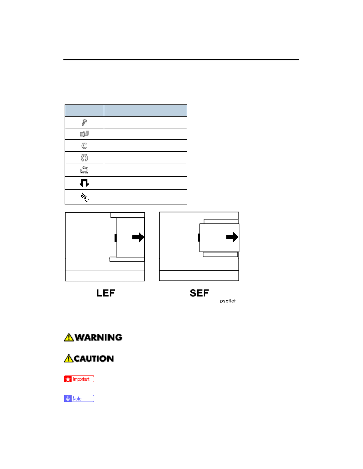
CONVENTIONS USED IN THIS MANUAL
This manual uses several symbols.
Symbol What It Means
Screw
Connector
E-ring
Clip ring
Clamp
Pawls (sensors)
Spring
Throughout this service manual, "SEF" denotes "Short Edge Feed" and "LEF" denotes "Long
Edge Feed".
Warnings, Cautions, Notes
In this manual, the following important symbols and notations are used.
A Warning indicates a potentially hazardous situation. Failure to obey a Warning
could result in death or serious injury.
A Caution indicates a potentially hazardous situation. Failure to obey a Caution
could result in minor or moderate injury or damage to the machine or other property.
Obey these guidelines to avoid problems such as misfeeds, damage to originals,
loss of valuable data and to prevent damage to the machine
This information provides tips and advice about how to best service the machine.
Trademarks
Microsoft®, Windows®, and MS-DOS® are registered trademarks of Microsoft
Corporation in the United States and /or other countries.
PostScript
®
is a registered trademark of Adobe Systems, Incorporated.
PCL
®
is a registered trademark of Hewlett-Packard Company.
Ethernet
®
is a registered trademark of Xerox Corporation.
PowerPC
®
is a registered trademark of International Business Machines Corporation.
Other product names used herein are for identification purposes only and may be
trademarks of their respective companies. We disclaim any and all rights involved with
those marks.
SAFETY INSTRUCTIONS
For your safety, please read this manual carefully before you service machine. Always keep
this manual handy for future reference.
- Safety Information -
Always obey the these safety precautions when using this product.
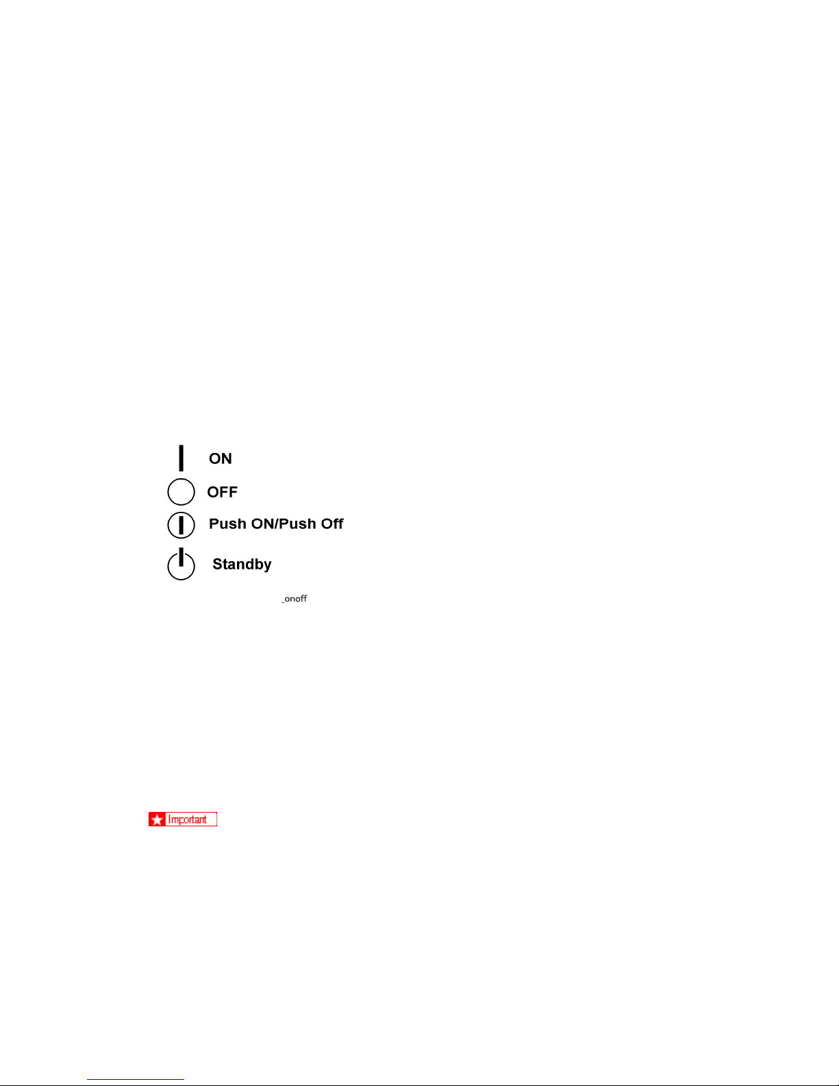
-
Switches and Symbols -
Where symbols are used on or near switches on machines for Europe and other areas, the
meaning of each symbol conforms with IEC60417.
RESPONSIBILITIES OF THE SERVICE TECHNICIAN
- Maintenance -
Maintenance shall be done only by trained customer engineers who have completed service
training for the machine and all optional devices designed for use with the machine.
- Installation -
The main machine and options can be installed by either the customer or customer engineer.
The customer or customer engineer must follow the installation instructions described in the
operating instructions.
- Reference Material for Maintenance -
Maintenance shall be done with the special tools and the procedures prescribed for
maintenance of the machine described in the reference materials (service manuals, technical
bulletins, operating instructions, and safety guidelines for customer engineers).
Use only consumable supplies and replacement parts designed for use with the
machine.
BEFORE INSTALLATION OR MAINTENANCE
- Shipping and Moving the Machine -
Work carefully when lifting or moving the machine. If the machine is heavy, two or
more customer engineers may be required to prevent injuries (muscle strains, spinal
injuries, etc.) or damage to the machine if it is dropped or tipped over.
Personnel moving or working around the machine should always wear proper
clothing and footwear. Never wear loose fitting clothing or accessories (neckties,
loose sweaters, bracelets, etc. ) or casual footwear (slippers, sandals, etc.) when
lifting or moving the machine.
Always unplug the power cord from the power source before you move the machine.
Before you move the machine, arrange the power cord so it will not fall under the
machine.
- Power -
Always turn the machine off and disconnect the power plug before doing any
maintenance procedure. After turning the machine off, power is still supplied to the
main machine and other devices. To prevent electrical shock, switch the machine
off, wait for a few seconds, then unplug the machine from the power source.
Before you do any checks or adjustments after turning the machine off, work
carefully to avoid injury. After removing covers or opening the machine to do checks
or adjustments, avoid touching electrical components or moving parts (gears, timing
belts, etc.).
After turning the machine on with any cover removed, keep your hands away from
electrical components and moving parts. Never touch the cover of the fusing unit,
gears, timing belts, etc.
- Installation, Disassembly, and Adjustments -
After installation, maintenance, or adjustment, always check the operation of the
machine to make sure that it is operating normally. This ensures that all shipping
materials, protective materials, wires and tags, metal brackets, etc., (attached to
protect the machine during shipping), have been removed and that no tools remain
inside the machine.
Never use your fingers to check moving parts that are causing spurious noise.
Never use your fingers to lubricate moving parts while the machine is operating.
- Special Tools -
Use only standard tools approved for machine maintenance.
For special adjustments, use only the special tools and lubricants described in the
service manual. Using tools incorrectly, or using tools that could damage parts,
could damage the machine or cause injuries.
DURING MAINTENANCE
- General -
Before you begin a maintenance procedure always switch the machine off.
Disconnect the power plug from the power source.
Allow the machine to cool for at least 10 minutes.
Avoid touching the components inside the machine that are labeled as hot surfaces.
- Safety Devices -
Never remove any safety device (a fuse, thermistor, etc.) unless it requires
replacement. Always replace a safety device immediately.
Never do any procedure that defeats the function of any safety device. Modification
or removal of a safety device (fuse, thermistor, etc.) could cause a fire and personal
injury. After removal and replacement of any safety device, always test the operation
of the machine to ensure that it is operating normally and safely.
For replacement parts use only the correct fuses, thermistors, circuit breakers, etc.
rated for use with the machine. Using replacement devices not designed for use with
the machine could cause a fire and personal injuries.
- Organic Cleaners -
During preventive maintenance, never use any organic cleaners (alcohol, etc.) other
than those described in the service manual. (Refer the “2. Preventive Maintenance”
in the Service Manual.)
Make sure the room is well ventilated before using any organic cleaner. Always use
organic solvents in small amounts to avoid breathing the fumes and becoming
nauseous.
Switch the machine off, unplug it, and allow it to cool before doing preventive
maintenance. To avoid fire or explosion, never use an organic cleaner near any
component that generates heat.
Wash your hands thoroughly after cleaning parts with an organic cleaner to avoid
contamination of food, drinks, etc. which could cause illness.
- Lithium Batteries -
Always replace a lithium battery on a PCB with the same type of battery prescribed
for use on that board. Replacing a lithium battery with any type other than the one
prescribed for use on the board could lead to an explosion or damage to the PCB.
Never discard used batteries by mixing them with other trash. Remove them from
the work site and dispose of them in accordance with local laws and regulations
regarding the disposal of such items.
- Ozone Filters -
Always replace ozone filters as soon as their service life expires (as described in the
service manual). An excessive amount of ozone can build up around machines that
use ozone filters if they are not replaced at the prescribed time. Excessive ozone
could cause personnel working around the machine to feel unwell.
- Power Plug and Power Cord -
Before serving the machine (especially when responding to a service call), always
make sure that the power plug has been inserted completely into the power source.
A partially inserted plug could lead to heat generation (due to a power surge caused
by high resistance) and cause a fire or other problems.
Always check the power plug and make sure that it is free of dust and lint. Clean it if
necessary. A dirty plug can generate heat which could cause a fire.
Inspect the length of the power cord for cuts or other damage. Replace the power
cord if necessary. A frayed or otherwise damaged power cord can cause a short
circuit which could lead to a fire or personal injury from electrical shock.

Check the length of the power cord between the machine and power supply. Make
sure the power cord is not coiled or wrapped around any object such as a table leg.
Coiling the power cord can cause excessive heat to build up and could cause a fire.
Make sure that the area around the power source is free of obstacles so the power
cord can be removed quickly in case of an emergency.
Make sure that the power cord is grounded (earthed) at the power source with the
ground wire on the plug.
Connect the power cord directly into the power source. Never use an extension
cord.
When you disconnect the power plug from the power source, always pull on the
plug, not the cable.
AFTER INSTALLATION
- Disposal of Used Items -
Ink is flammable. Never attempt to incinerate empty ink cartridges.
Always dispose of used items in accordance with the local laws and regulations
regarding the disposal of such items.
To protect the environment, never dispose of this product or any kind of waste from
consumables at a household waste collection point. Dispose of these items at one of
our dealers or at an authorized collection site.
- Points to Confirm with Operators -
At the end of installation or a service call, instruct the user about use of the machine.
Emphasize the following points.
Show operators how to remove jammed paper and troubleshoot other minor problems
by following the procedures described in the operating instructions.
Point out the parts inside the machine that they should never touch or attempt to
remove.
Confirm that operators know how to store and dispose of consumables such as ink
cartridges, ammonia water, paper, etc..
Make sure that all operators have access to an operating instruction manual for the
machine.
Confirm that operators have read and understand all the safety instructions described in
the operating instructions.
Demonstrate how to turn off the power and disconnect the power plug (by pulling the
plug, not the cord) if any of the following events occur:
1. Something has spilled into the product.
2. Service or repair of the product is necessary.
3. The product cover has been damaged.
Caution operators about removing paper fasteners around the machine. They should
never allow paper clips, staples, or any other small metallic objects to fall into the
product.
The operator must lift the output tray to release the paper cassette before
loading paper.
Paper is loaded in the standard paper cassette without removing it from the
printer.
The operator should never attempt to remove the paper cassette from the
printer.

SAFETY INSTRUCTIONS FOR TONER AND INK
This section describes information for users in regard to the use of toner and ink.
ACCIDENTAL PHYSICAL EXPOSURE
- PPC Toner Exposure -
Work carefully when removing paper jams or replacing toner bottles or cartridges to
avoid spilling toner on clothing or the hands.
If toner is inhaled, immediately gargle with large amounts of cold water and move to
a well ventilated location. If there are signs of irritation or other problems, seek
medical attention.
If toner gets on the skin, wash immediately with soap and cold running water.
If toner gets into the eyes, flush the eyes with cold running water or eye wash. If
there are signs of irritation or other problems, seek medical attention.
If toner is swallowed, drink a large amount of cold water to dilute the ingested toner.
If there are signs of any problem, seek medical attention.
If toner spills on clothing, wash the affected area immediately with soap and cold
water. Never use hot water! Hot water can cause toner to set and permanently stain
fabric.
- Ink Exposure -
If ink gets on the skin, wash the affected area immediately with soap and cold
running water.
If ink gets into the eyes, immediately flush the eyes with cold running water. If there
are signs of irritation or other problems, seek medical attention.
If ink is swallowed, drink a strong solution of cold water and table salt to induce
vomiting. Seek medical attention.
Ink is difficult to remove from fabric. Work carefully to avoid staining clothing when
performing routine maintenance replacing ink packs or ink cartridges.
HANDLING AND STORING TONER AND INK
- Handling and Storing PPC Toner -
Toner, used toner, and developer are extremely flammable. Never store toner,
developer, toner cartridges, or toner bottles (including empty toner bottles or
cartridges) in a location where they will be exposed to high temperature or an open
flame.
Always store toner and developer supplies such as toner and developer packages,
cartridges, and bottles (including used toner and empty bottles and cartridges) out of
the reach of children.
Always store fresh toner supplies or empty bottles or cartridges in a cool, dry
location that is not exposed to direct sunlight.
- Handling and Storing Ink -
Ink is flammable. Never store ink packs in a location where they will be exposed to
high temperature or an open flame.
Always store ink packs out of the reach of children.
Always store ink packs in a cool, dry location that is not exposed to direct sunlight.
TONER AND INK DISPOSAL
- PPC Toner Disposal -
Never attempt to incinerate toner, used toner, or empty toner containers (bottles or
cartridges). Burning toner can explode and scatter, causing serious burns.
Always wrap used toner and empty toner bottles and cartridges in plastic bags to
avoid spillage. Follow the local laws and regulations regarding the disposal of such
items.
Dispose of used toner and toner cartridges at one of our dealers or at an authorized
collection site. Always dispose of used toner cartridges and toner bottles in
accordance with the local laws and regulations regarding the disposal of such items.
- Ink Disposal -
Attach the caps to empty ink containers for temporary storage to avoid accidental
spillage. Return empty ink packs and cartridges to a local dealer who can accept
such items for collection and recycling. If the customer decides to dispose of these
items, make sure that are disposed of in accordance to local laws and regulations.
SAFETY PRECAUTIONS FOR THIS MACHINE
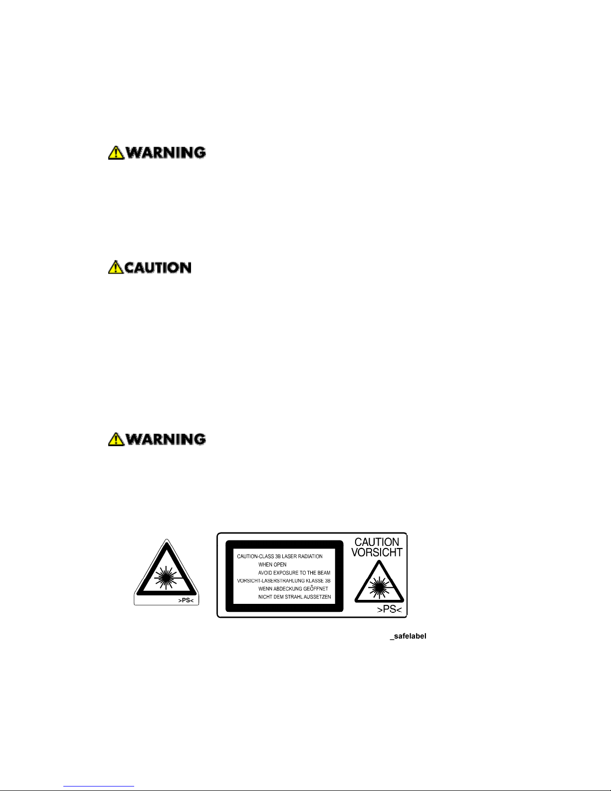
LASER SAFETY
The Center for Devices and Radiological Health (CDRH) prohibits the repair of laser-based
optical units in the field. The optical housing unit can only be repaired in a factory or at a
location with the requisite equipment. The laser subsystem is replaceable in the field by a
qualified Customer Engineer. The laser chassis is not repairable in the field. Customer
engineers are therefore directed to return all chassis and laser subsystems to the factory or
service depot when replacement of the optical subsystem is required.
Use of controls, or adjustment, or performance of procedures other than those
specified in this manual may result in hazardous radiation exposure.
Turn off the main switch before attempting any of the procedures in the Laser Unit
section. Laser beams can seriously damage your eyes.
CAUTION LABELS

LITHIUM BATTERIES (MEMORY BACK-UP)
The danger of explosion exists if a battery of this type is incorrectly replaced.
Replace only with the same or an equivalent type recommended by the
manufacturer. Discard used batteries in accordance with the manufacturer’s
instructions.

INSTALLATION
PREVENTIVE MAINTENANCE
G839 PAPER FEED UNIT
REPLACEMENT AND ADJUSTMENT
B543 LARGE CAPACITY TRAY
TROUBLESHOOTING
B377 PUNCH UNIT
G838 FINISHER
SERVICE TABLES
DETAILED DESCRIPTIONS
SPECIFICATIONS
B538 BRIDGE UNIT
TAB
POSITION 2
TAB
POSITION 1
TAB
POSITION 3
TAB
POSITION 4
TAB
POSITION 6
TAB
POSITION 5
TAB
POSITION 8
TAB
POSITION 7

 Loading...