

Ricoh G108 Service Manual
G108
SERVICE MANUAL
002011MIU
RICOH GROUP COMPANIES


G108
SERVICE MANUAL
RICOH GROUP COMPANIES
®
®


G108
SERVICE MANUAL
002011MIU


It is the reader's respon
sibility when discussing the information contained
within this document to maintain a level of confidentiality that is in the best
interest of Ricoh Corporation and its member companies.
NO PART OF THIS DOCUMENT MAY BE REPRODUCED IN ANY
FASHION AND DISTRIBUTED WITHOUT THE PRIOR
PERMISSION OF RICOH CORPORATION.
All product names, domain names or product illustrations, including
desktop images, used in this document are trademarks, registered
trademarks or the property of their respective companies.
They
are used throughout this book in an informational or editorial fashion
only and for the benefit of such companies. No such use, or the use of
any trade name, or web site is intended to convey endorsement or other
affiliation with Ricoh products.
2004 RICOH Corporation. All rights reserved.


The Service Manual contains information
regarding service techniques, procedures,
processes and spare parts of office equipment
distributed by Ricoh Corporation. Users of this
manual should be either service trained or
certified by successfully comple
ting a Ricoh
Technical Training Program.
Untrained and uncertified users utilizing
information contained in this service manual to
repair or modify Ricoh equipment risk personal
injury, damage to property or loss of warranty
protection.
Ricoh Corporation
WARNING


LEGEND
PRODUCT CODE COMPANY
GESTETNER LANIER RICOH SAVIN
G108 P7431cn LP031c Aficio CL1000N
CLP831
DOCUMENTATION HISTORY
REV. NO. DATE COMMENTS
*
6/2004 Original Printing


G108
TABLE OF CONTENTS
INSTALLATION
1. INSTALLATION............................................................................ 1-1
1.1 INSTALLATION REQUIREMENTS ...........................................................1-1
1.1.1 ENVIRONMENT ...............................................................................1-1
1.1.2 MACHINE LEVEL.............................................................................1-1
1.1.3 MACHINE SPACE REQUIREMENT.................................................1-2
Printer Only...........................................................................................1-2
Printer and Duplex Unit.........................................................................1-2
1.1.4 POWER REQUIREMENT.................................................................1-3
1.2 INSTALLATION PROCEDURE .................................................................1-4
1.2.1 INSTALLING THE PRINTER............................................................1-4
1.2.2 NECESSARY SETTINGS.................................................................1-4
1.3 MOVING THE MACHINE ..........................................................................1-5
PREVENTIVE MAINTENANCE
2. PREVENTIVE MAINTENANCE.................................................... 2-1
2.1 USER MAINTENANCE .............................................................................2-1
Page Count...........................................................................................2-1
2.2 SERVICE MAINTENANCE........................................................................ 2-2
Necessary Setting................................................................................. 2-2
Page Count...........................................................................................2-2
REPLACEMENT AND ADJUSTMENT
3. REPLACEMENT AND ADJUSTMENT ........................................ 3-1
3.1 EXTERIOR COVERS ................................................................................3-1
3.1.1 TOP COVER ....................................................................................3-1
3.1.2 RIGHT COVER.................................................................................3-2
3.1.3 LEFT COVER ...................................................................................3-2
3.1.4 FRONT COVER................................................................................3-3
3.1.5 REAR COVER..................................................................................3-3
3.2 OPTICS UNIT............................................................................................3-4
3.2.1 CAUTION DECAL LOCATION .........................................................3-4
3.2.2 REMOVING THE LASER OPTICS UNIT..........................................3-4
3.3 OPC...........................................................................................................3-5
3.3.1 OPC BELT UNIT...............................................................................3-5
3.3.2 OPC BELT SENSOR........................................................................ 3-5
3.3.3 CHARGE ROLLER AND CLEANING ROLLER................................3-6
3.3.4 ERASE LAMP...................................................................................3-7
SM i G108

3.4 DEVELOPMENT .......................................................................................3-8
3.4.1 TONER END SENSOR ....................................................................3-8
Emitter ..................................................................................................3-8
Receptor ...............................................................................................3-8
3.4.2 DEVELOPMENT UNIT SENSOR AND DEVELOPMENT CLUTCH . 3-9
3.5 TRANSFER BELT ...................................................................................3-10
3.5.1 TRANSFER BELT UNIT .................................................................3-10
3.5.2 TRANSFER BELT SENSOR AND ID SENSOR .............................3-10
3.5.3 TRANSFER BELT CLEANING UNIT AND WASTE TONER DUCT3-11
3.6 WASTE TONER COLLECTION UNIT .....................................................3-12
3.6.1 WASTE TONER BOTTLE ..............................................................3-12
3.6.2 WASTE TONER BOTTLE HOLDER...............................................3-12
3.6.3 WASTE TONER DUCT ..................................................................3-13
3.7 PAPER FEED..........................................................................................3-14
3.7.1 PAPER FEED ROLLER AND SEPARATOR PAD.......................... 3-14
3.7.2 OHP SENSOR, PAPER END SENSOR, AND REGISTRATION
SENSOR ........................................................................................3-14
3.7.3 TEMPERATURE SENSOR, PAPER SIZE SENSOR AND
PAPER TRAY SENSOR.................................................................3-15
3.8 PAPER TRANSFER AND PAPER EXIT .................................................3-16
3.8.1 TRANSFER ROLLER UNIT............................................................3-16
3.8.2 PAPER EXIT SENSOR AND PAPER OVERFLOW SENSOR .......3-16
3.8.3 DISCHARGE BRUSH.....................................................................3-17
3.9 FUSING UNIT AND FUSING LAMP........................................................3-18
3.10 CIRCUIT BOARD ..................................................................................3-20
3.10.1 CONTROLLER AND BASE ENGINE CONTROL UNIT................3-20
3.10.2 INPUT OUTPUT DEVICE.............................................................3-21
3.10.3 DIRECT CURRENT UNIT ............................................................3-22
3.10.4 HIGH VOLTAGE UNIT .................................................................3-23
3.11 DRIVE PATH .........................................................................................3-24
3.11.1 MAIN MOTOR DRIVE PATH........................................................3-24
3.11.2 DEVELOPMENT MOTOR DRIVE PATH......................................3-26
3.12 EXHAUST FAN .....................................................................................3-27
3.12.1 OPTICS UNIT FAN....................................................................... 3-27
3.12.2 PSU FAN ......................................................................................3-27
3.12.3 FUSING FAN................................................................................3-28
3.13 INTERLOCK SWITCH...........................................................................3-29
3.13.1 FRONT COVER SWITCH ............................................................3-29
3.13.2 TOP AND REAR COVER SWITCHES .........................................3-29
3.14 REGISTRATION....................................................................................3-30
3.14.1 LEADING EDGE REGISTRATION............................................... 3-30
3.14.2 SIDE-TO-SIDE REGISTRATION.................................................. 3-31
TROUBLESHOOTING
4. TROUBLESHOOTING ................................................................. 4-1
4.1 SERVICE CALL.........................................................................................4-1
4.1.1 SUMMARY .......................................................................................4-1
G108 ii SM

4.1.2 SC CODE CLASSIFICATION...........................................................4-2
4.1.3 SC TABLE ........................................................................................4-3
4.2 IMAGE QUALITY.......................................................................................4-8
4.2.1 BACKGROUND................................................................................4-8
Symptom...............................................................................................4-8
Possible Cause.....................................................................................4-8
Countermeasures .................................................................................4-8
4.2.2 MISSING IMAGE AT EDGE .............................................................4-8
Symptom...............................................................................................4-8
Possible Cause.....................................................................................4-8
Countermeasures .................................................................................4-8
4.2.3 JITTER .............................................................................................4-9
Symptom...............................................................................................4-9
Possible Cause.....................................................................................4-9
Countermeasures .................................................................................4-9
4.2.4 RIBBING.........................................................................................4-10
Symptom.............................................................................................4-10
Possible Cause................................................................................... 4-10
Countermeasures ...............................................................................4-10
4.2.5 WRINKLE/IMAGE MIGRATION .....................................................4-11
Symptom.............................................................................................4-11
Possible Cause................................................................................... 4-11
Countermeasures ...............................................................................4-11
4.2.6 WHITE LINE 1 ................................................................................4-11
Symptom.............................................................................................4-11
Possible Cause................................................................................... 4-11
Countermeasures ...............................................................................4-11
4.2.7 WHITE LINE 2 ................................................................................4-12
Symptom.............................................................................................4-12
Possible Cause................................................................................... 4-12
Countermeasures ...............................................................................4-12
4.2.8 VERTICAL WHITE BAND...............................................................4-12
Symptom.............................................................................................4-12
Possible Cause................................................................................... 4-12
Countermeasures ...............................................................................4-12
4.2.9 BLACK LINE...................................................................................4-13
Symptom.............................................................................................4-13
Possible Cause................................................................................... 4-13
Countermeasures ...............................................................................4-13
4.2.10 VERTICAL LINE ...........................................................................4-13
Symptom.............................................................................................4-13
Possible Cause................................................................................... 4-13
Countermeasures ...............................................................................4-13
4.2.11 VERTICAL LINES NOT ACCEPTABLY STRAIGHT.....................4-14
Symptom.............................................................................................4-14
Possible Cause................................................................................... 4-14
Countermeasures ...............................................................................4-14
4.2.12 BANDING .....................................................................................4-14
Symptom.............................................................................................4-14
SM iii G108

Possible Cause................................................................................... 4-14
Countermeasures ...............................................................................4-14
4.2.13 WHITE BAND ...............................................................................4-15
Symptom.............................................................................................4-15
Possible Cause................................................................................... 4-15
Countermeasures ...............................................................................4-15
4.2.14 TONER SPOTS............................................................................ 4-15
Symptom.............................................................................................4-15
Possible Cause................................................................................... 4-15
Countermeasures ...............................................................................4-15
4.2.15 WHITE SPOTS / BLACK SPOTS .................................................4-16
Symptom.............................................................................................4-16
Possible Cause................................................................................... 4-16
Countermeasures ...............................................................................4-16
4.2.16 MIXED COLOR IMAGE ................................................................4-16
Symptom.............................................................................................4-16
Possible Cause................................................................................... 4-16
Countermeasures ...............................................................................4-16
4.2.17 INCORRECT COLOR REGISTRATION.......................................4-17
Symptom.............................................................................................4-17
Possible Cause................................................................................... 4-17
Countermeasures ...............................................................................4-17
4.2.18 MOTTLING ...................................................................................4-17
Symptom.............................................................................................4-17
Possible Cause................................................................................... 4-17
Countermeasures ...............................................................................4-17
4.2.19 RESIDUAL IMAGE ....................................................................... 4-18
Symptom.............................................................................................4-18
Possible Cause................................................................................... 4-18
Countermeasures ...............................................................................4-18
4.2.20 UNEVEN GLOSSINESS...............................................................4-18
Symptom.............................................................................................4-18
Possible Cause................................................................................... 4-18
Countermeasures ...............................................................................4-18
4.2.21 BACK STAIN ................................................................................4-19
Symptom.............................................................................................4-19
Possible Cause................................................................................... 4-19
Countermeasures ...............................................................................4-19
4.2.22 BLANK IMAGE .............................................................................4-19
Symptom.............................................................................................4-19
Possible Cause................................................................................... 4-19
Countermeasures ...............................................................................4-19
4.2.23 INSUFFICIENT FUSING ..............................................................4-20
Symptom.............................................................................................4-20
Possible Cause................................................................................... 4-20
Countermeasures ...............................................................................4-20
4.2.24 UNEVEN DENSITY BETWEEN LEFT AND RIGHT SIDES .........4-20
Symptom.............................................................................................4-20
Possible Cause................................................................................... 4-20
G108 iv SM

Countermeasures ...............................................................................4-20
4.2.25 UNEVEN DENSITY AMONG DIFFERENT PAGES .....................4-21
Symptom.............................................................................................4-21
Possible Cause................................................................................... 4-21
Countermeasures ...............................................................................4-21
4.3 ELECTRICAL COMPONENT .................................................................. 4-22
4.3.1 SENSORS ......................................................................................4-22
Reflective Photo Sensors....................................................................4-22
Photo Sensors ....................................................................................4-22
4.3.2 BLOWN FUSE CONDITION...........................................................4-23
4.3.3 LED.................................................................................................4-23
Operation Panel.................................................................................. 4-23
Controller ............................................................................................4-23
BCU .................................................................................................... 4-23
4.4 DUPLEX UNIT..........................................................................................4-23
SERVICE TABLES
5. SERVICE TABLES....................................................................... 5-1
5.1 SERVICE PROGRAM MODE....................................................................5-1
5.1.1 OPERATING SERVICE PROGRAM MODE.....................................5-1
Activating SP Mode...............................................................................5-1
Selecting a Service Program ................................................................5-2
Specifying a Setting ..............................................................................5-2
Quitting SP Mode..................................................................................5-2
5.1.2 SERVICE..........................................................................................5-3
Tables ...................................................................................................5-3
Bit Switches ..........................................................................................5-6
Adjusting Printer Gamma......................................................................5-7
Toner Control Set (Service SP1-101) ...................................................5-9
5.1.3 ENGINE..........................................................................................5-10
SP1: Feed...........................................................................................5-10
SP2: Drum ..........................................................................................5-11
SP5: Mode ..........................................................................................5-12
SP7: Data Log ....................................................................................5-22
SP8: Data Log 2 .................................................................................5-27
5.1.4 MEMORY CLEAR/COUNTER CLEAR ...........................................5-36
5.1.5 TELEPHONE NUMBER SETTING (SP5-812)................................ 5-37
5.2 FIRMWARE UPDATE .............................................................................5-38
5.2.1 TYPES OF FIRMWARE .................................................................5-38
5.2.2 PRECAUTIONS.............................................................................. 5-38
Handling SD Card............................................................................... 5-38
Upload or Download ...........................................................................5-38
Network Connection............................................................................5-38
5.2.3 FILE ARRANGEMENT ...................................................................5-39
How The Program Works....................................................................5-39
Example..............................................................................................5-39
5.2.4 UPDATING .....................................................................................5-40
SM v G108

Procedure ...........................................................................................5-40
Error Handling..................................................................................... 5-41
Power Failure......................................................................................5-41
5.2.5 NVRAM DATA UPLOAD/DOWNLOAD ..........................................5-41
Uploading NVRAM Data ..................................................................... 5-41
Downloading NVRAM Data.................................................................5-42
5.2.6 ERROR CODE TABLE ...................................................................5-43
5.3 SD CARD APPLI MOVE.......................................................................... 5-44
5.3.1 OVERVIEW ....................................................................................5-44
5.3.2 MOVE EXEC ..................................................................................5-45
5.3.3 UNDO EXEC ..................................................................................5-46
5.4 CONTROLLER SELF-DIAGNOSTICS ....................................................5-47
5.4.1 OVERVIEW ....................................................................................5-47
5.4.2 DETAILED SELF-DIAGNOSTICS ..................................................5-48
5.5 TONER DENSITY (MASS AMOUNT) CONTROL ...................................5-49
5.5.1 OVERVIEW ....................................................................................5-49
5.5.2 TMA CONTROL SWITCH ..............................................................5-49
5.5.3 ADJUSTING DEVELOPMENT BIAS .............................................. 5-50
5.5.4 TMA STATUS.................................................................................5-50
5.6 USER PROGRAM MODE .......................................................................5-51
Starting User Program ........................................................................5-51
Quitting User Program ........................................................................5-51
Menu List ............................................................................................5-51
5.7 DIP SWITCHES.......................................................................................5-52
Controller Board.................................................................................. 5-52
BCU Board..........................................................................................5-52
DETAILED DESCRIPTIONS
6. DETAILED DESCRIPTIONS ........................................................ 6-1
6.1 OVERVIEW ...............................................................................................6-1
6.1.1 COMPONENT LAYOUT ...................................................................6-1
6.1.2 PAPER PATH...................................................................................6-2
6.1.3 DRIVE LAYOUT ...............................................................................6-3
6.1.4 BOARD STRUCTURE......................................................................6-4
Controller ..............................................................................................6-5
Base Engine Control Unit (BCU)...........................................................6-5
Input Output Device (IOD) ....................................................................6-5
Power Supply Unit and High Voltage Unit.............................................6-5
6.1.5 PRINTING PROCEDURE.................................................................6-6
6.2 TONER MASS AMOUNT CONTROL........................................................6-8
6.2.1 OVERVIEW ......................................................................................6-8
6.2.2 ID SENSOR CALIBRATION .............................................................6-8
6.2.3 TEST PATTERN PROCESSING......................................................6-9
6.2.4 REFERENCE EQUATION PROCESSING .....................................6-10
6.2.5 DEVELOPMENT BIAS ADJUSTMENT ..........................................6-10
6.3 OPTICAL HOUSING UNIT ......................................................................6-11
6.3.1 OPTICAL PATH..............................................................................6-11
G108 vi SM

6.3.2 LASER SYNCHRONIZATION ........................................................6-12
6.3.3 SPECIFICATIONS..........................................................................6-12
6.3.4 OPTICS UNIT FAN.........................................................................6-13
6.3.5 LASER EXPOSURE ....................................................................... 6-13
6.3.6 SAFETY SWITCH...........................................................................6-14
6.4 OPC BELT............................................................................................... 6-15
6.4.1 DRIVE.............................................................................................6-15
6.4.2 OPC BELT CLEANING...................................................................6-15
6.4.3 CHARGE ROLLER AND CLEANING ROLLER..............................6-16
6.4.4 OPC BELT SENSOR...................................................................... 6-17
6.4.5 QUENCHING..................................................................................6-17
6.5 DEVELOPMENT UNIT ............................................................................6-18
6.5.1 OVERVIEW ....................................................................................6-18
6.5.2 DEVELOPMENT UNIT SENSOR ...................................................6-18
6.5.3 DRIVE.............................................................................................6-19
6.5.4 DEVELOPMENT UNIT CONTACT MECHANISM .......................... 6-20
Contact Mechanism ............................................................................6-20
Spring Clutch ......................................................................................6-21
6.5.5 DEVELOPMENT BIAS ...................................................................6-21
6.5.6 TONER END SENSOR ..................................................................6-22
Arrangement .......................................................................................6-22
Mechanism .........................................................................................6-22
Near End and End ..............................................................................6-22
6.6 TRANSFER BELT ...................................................................................6-23
6.6.1 DRIVE.............................................................................................6-23
6.6.2 TRANSFER BELT SENSOR AND ID SENSOR .............................6-24
Transfer Belt Sensor...........................................................................6-24
ID Sensor............................................................................................6-24
ID Sensor Cleaning............................................................................. 6-25
6.6.3 TRANSFER BELT CLEANING .......................................................6-26
Cleaning Mechanism ..........................................................................6-26
Drive ...................................................................................................6-26
Contact-Release Mechanism..............................................................6-27
Waste Toner Agitator .......................................................................... 6-28
6.6.4 WASTE-TONER COLLECTION UNIT ............................................6-29
Overview.............................................................................................6-29
Drive ...................................................................................................6-29
Waste Toner Sensor ........................................................................... 6-30
Messages ...........................................................................................6-30
Near-Full and Full ...............................................................................6-30
6.7 PAPER TRAY UNIT ................................................................................6-31
6.7.1 OVERVIEW ....................................................................................6-31
6.7.2 PAPER LIFT ...................................................................................6-32
6.7.3 PAPER FEED.................................................................................6-33
Paper Feed Roller...............................................................................6-33
Drive ...................................................................................................6-33
6.7.4 PAPER SIZE AND PAPER TRAY DETECTION............................. 6-34
Mechanism .........................................................................................6-34
Paper Size ..........................................................................................6-34
SM vii G108

6.7.5 OHP SENSOR................................................................................ 6-35
Reflective Photosensor .......................................................................6-35
Configuration Page and Utilities..........................................................6-35
OHP Sensor, User Setting, and Printer Driver ....................................6-36
6.7.6 PAPER END SENSOR...................................................................6-37
6.8 PAPER REGISTRATION AND PAPER TRANSFER...............................6-38
6.8.1 PAPER REGISTRATION................................................................6-38
Registration Roller ..............................................................................6-38
Drive ...................................................................................................6-38
Registration Sensor ............................................................................6-38
6.8.2 PAPER TRANSFER .......................................................................6-39
Transfer Roller ....................................................................................6-39
Paper Transfer Bias............................................................................6-39
Discharge Plate ..................................................................................6-39
Contact Release Mechanism ..............................................................6-39
6.9 FUSING UNIT..........................................................................................6-40
6.9.1 OVERVIEW ....................................................................................6-40
6.9.2 DRIVE.............................................................................................6-41
6.9.3 PRESSURE UNIT...........................................................................6-41
6.9.4 FUSING PROCESS........................................................................6-41
6.9.5 TEMPERATURE CONTROL ..........................................................6-42
Main Components...............................................................................6-42
Temperature .......................................................................................6-43
Energy Saver Mode ............................................................................6-43
6.10 PAPER EXIT UNIT ................................................................................6-44
Drive ...................................................................................................6-44
Paper Exit Sensor...............................................................................6-44
Paper Exit Overflow Sensor................................................................6-44
6.11 CONTROLLER ......................................................................................6-45
6.11.1 OVERVIEW ..................................................................................6-45
6.11.2 BOARD LAYOUT..........................................................................6-46
6.11.3 CONTROLLER FUNCTIONS .......................................................6-47
Tray Priority ........................................................................................6-47
Tray Locking .......................................................................................6-47
Manual Tray Select............................................................................. 6-47
Auto Continue .....................................................................................6-47
6.11.4 BLACK OVER PRINT ...................................................................6-48
Black Over Print Disabled ...................................................................6-48
Black Over Print Enabled....................................................................6-48
6.11.5 NETWORK DATA PROTECTION UNIT .......................................6-49
NDPU and DES ..................................................................................6-49
Supported Network Interface ..............................................................6-49
6.12 ETHERNET BOARD .............................................................................6-50
6.12.1 ETHERNET BOARD LAYOUT .....................................................6-50
6.12.2 ETHERNET ..................................................................................6-51
6.13 USB 2.0 .................................................................................................6-52
6.13.1 GENERAL FEATURES ................................................................6-52
Overview.............................................................................................6-52
Plug and Play...................................................................................... 6-52
G108 viii SM

Hot Plugging .......................................................................................6-52
USB 2.0 and 1.1 .................................................................................6-52
6.13.2 USB CONNECTORS....................................................................6-52
6.13.3 PIN ASSIGNMENT ....................................................................... 6-53
6.13.4 REMARKS....................................................................................6-53
Related SP Mode................................................................................ 6-53
6.14 IEEE 802.11B (WIRELESS LAN) ..........................................................6-54
6.14.1 SPECIFICATIONS........................................................................6-54
LED Indicators ....................................................................................6-54
6.14.2 TRANSMISSION MODES ............................................................6-55
Ad Hoc Mode ......................................................................................6-55
Infrastructure Mode............................................................................. 6-55
6.14.3 SECURITY FEATURES ...............................................................6-56
Service Set ID.....................................................................................6-56
SSID in Ad hoc mode..........................................................................6-56
Wired Equivalent Privacy (WEP) ........................................................6-56
MAC Address...................................................................................... 6-56
6.14.4 TROUBLESHOOTING..................................................................6-57
Communication Status........................................................................6-57
Channel Settings ................................................................................6-57
Procedure ...........................................................................................6-58
6.15 BLUETOOTH.........................................................................................6-59
6.15.1 SPECIFICATIONS........................................................................6-59
6.15.2 BLOCK DIAGRAM........................................................................6-59
6.15.3 COMMUNICATION.......................................................................6-60
Piconet................................................................................................6-60
Frequency Hopping Spread Spectrum (FHSS)................................... 6-60
Profiles................................................................................................6-61
6.15.4 SECURITY FEATURES ...............................................................6-61
Public and Private Mode .....................................................................6-61
PIN Code (Personal Identification Number) ........................................6-61
SPECIFICATIONS
SPECIFICATIONS
1. PRINTER DRIVERS.....................................................................................7-1
2. SUPPORTED PAPER SIZES....................................................................... 7-3
3. SOFTWARE ACCESSORIES ......................................................................7-3
3.1 PRINTER DRIVERS............................................................................ 7-4
3.2 UTILITY SOFTWARE .......................................................................... 7-4
4. MACHINE CONFIGURATION...................................................................... 7-5
5. MACHINE CONFIGURATION...................................................................... 7-7
5.1 PAPER TRAY UNIT.............................................................................7-7
5.2 LEGAL PAPER TRAY .........................................................................7-7
5.3 DUPLEX UNIT................................................................................... 7-7
SM ix G108

G108 x SM
PAPER FEED UNIT G389
SEE SECTION G389 FOR DETAILED TABLE OF CONTENTS
DUPLEX UNIT G390
SEE SECTION G390 FOR DETAILED TABLE OF CONTENTS

IMPORTANT SAFETY NOTICES
PREVENTION OF PHYSICAL INJURY
1. Before disassembling or assembling parts of the printer and peripherals,
make sure that the printer power cord is unplugged.
2. The wall outlet should be near the printer and easily accessible.
3. If any adjustment or operation check has to be made with exterior covers off
or open while the main switch is turned on, keep hands away from electrified
or mechanically driven components.
4. The printer drives some of its components when it completes the warm-up
period. Be careful to keep hands away from the mechanical and electrical
components as the printer starts operation.
5. The inside and the metal parts of the fusing unit become extremely hot while
the printer is operating. Be careful to avoid touching those components with
your bare hands.
HEALTH SAFETY CONDITIONS
Toner and developer are non-toxic, but if you get either of them in your eyes by
accident, it may cause temporary eye discomfort. Try to remove with eye drops
or flush with water as first aid. If unsuccessful, get medical attention.
OBSERVANCE OF ELECTRICAL SAFETY STANDARDS
1. The printer and its peripherals must be serviced by a customer service
representative who has completed the training course on those models.
2. The NVRAM module (option) installed on the controller has a lithium battery
which can explode if replaced incorrectly. Replace the NVRAM only with an
identical one. The manufacturer recommends replacing the entire NVRAM.
Do not recharge or burn this battery. Used NVRAM must be handled in
accordance with local regulations.
SAFETY AND ECOLOGICAL NOTES FOR DISPOSAL
1. Do not incinerate toner bottles or used toner. Toner dust may ignite suddenly
when exposed to an open flame.
2. Dispose of used toner, the maintenance unit which includes developer or the
organic photoconductor in accordance with local regulations. (These are
non-toxic supplies.)
3. Dispose of replaced parts in accordance with local regulations.
4. When keeping used lithium batteries in order to dispose of them later, do not
put more than 100 batteries per sealed box. Storing larger numbers or not
sealing them apart may lead to chemical reactions and heat build-up.
LASER SAFETY
The Center for Devices and Radiological Health (CDRH) prohibits the repair of
laser-based optical units in the field. The optical housing unit can only be repaired
in a factory or at a location with the requisite equipment. The laser subsystem is
replaceable in the field by a qualified Customer Engineer. The laser chassis is not
repairable in the field. Customer engineers are therefore directed to return all
chassis and laser subsystems to the factory or service depot when replacement of
the optical subsystem is required.
WARNING
Use of controls, or adjustment, or performance of procedures other than
those specified in this manual may result in hazardous radiation exposure.
WARNING
WARNING: Turn off the main switch before attempting any of the
procedures in the Optics Unit section. Laser beams can
seriously damage your eyes.
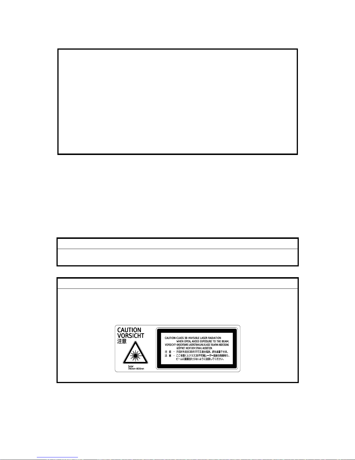
CAUTION MARKING:

Trademarks
Microsoft®, Windows®, and MS-DOS® are registered trademarks of Microsoft
Corporation in the United States and /or other countries.
PostScript® is a registered trademark of Adobe Systems, Incorporated.
PCL® is a registered trademark of Hewlett-Packard Company.
Ethernet® is a registered trademark of Xerox Corporation.
PowerPC® is a registered trademark of International Business Machines
Corporation.
Other product names used herein are for identification purposes only and may be
trademarks of their respective companies. We disclaim any and all rights involved
with those marks.
Symbols and Abbreviations
This manual uses the symbols and abbreviations shown below.
Symbol Meaning
Refer to section number
Clip ring
Screw
Connector
E ring
SEF Short Edge Feed
LEF Long Edge Feed
Long Edge Feed (LEF)Short Edge Feed (SEF)

INSTALLATION
PREVENTIVE MAINTENANCE
REPLACEMENT AND ADJUSTMENT
TROUBLESHOOTING
SERVICE TABLES
G390 DUPLEX UNIT AD460
DETAILED DESCRIPTIONS
SPECIFICATIONS
G389 PAPER FEED UNIT TYPE 1000
TAB
POSITION 2
TAB
POSITION 1
TAB
POSITION 3
TAB
POSITION 4
TAB
POSITION 6
TAB
POSITION 5
TAB
POSITION 8
TAB
POSITION 7


INSTALLATION

 Loading...