

Page 1
Setup Guide
For safety, please read this manual carefully before you use this product and keep it
handy for future reference.
Page 2

Introduction
This manual describes detailed instructions on the operation and notes about the use of this machine.
To get maximum versatility from this machine all operators are requested to read this manual carefully
and follow the instructions. Please keep this manual in a handy place near the machine.
Power Source
120 V, 60 Hz, 10 A or more
Please be sure to connect the power cable to a power source as above.
Operator Safety:
This machine is considered a CDRH class I laser device, safe for office/ EDP use. The machine contains 7 milliwatt, 645 - 660 nanometer wavelength, AlGaInp Laser Diode. Direct (or indirect reflected)
eye contact with the laser beam might cause serious eye damage. Safety precautions and interlock
mechanisms have been designed to prevent any possible laser beam exposure to the operator.
Laser Safety:
The Center for Devices and Radiological Health (CDRH) prohibits the repair of laser-based optical unit
in the field. The optical housing unit can only be repaired in a factory or at a location with the requisite
equipment. The laser subsystem is replaceable in the field by a qualified Customer Engineer. The laser
chassis is not repairable in the field. Customer engineers are therefore directed to return all chassis
and laser subsystems to the factory or service depot when replacement or the optical subsystem is required.
Important
Contents of this manual are subject to change without prior notice. In no event will the company be liable for direct, indirect, special, incidental, or consequential damages as a result of handling or operating the machine.
Caution:
Use of controls or adjustment or performance of procedures other than those specified in this manual
might result in hazardous radiation exposure.
Do not attempt any maintenance or troubleshooting other than that mentioned in this manual. This
printer contains a laser beam generator and direct exposure to laser beams can cause permanent eye
damage.
Two kinds of size notation are employed in this manual. With this machine refer to the inch version.
For good copy quality, the supplier recommends that you use genuine toner from the supplier.
The supplier shall not be responsible for any damage or expense that might result from the use of parts
other than genuine parts from the supplier with your office products.
Page 3

Trademarks
Microsoft, Windows, and Windows NT are registered trademarks of Microsoft
Corporation in the United States and/or other countries.
IPS-PRINT Printer Language Emulation Copyright© 1999-2000 Oak Technology, Inc., All rights reserved.
Ethernet is a registered trademark of Xerox Corporation.
Other product names used herein are for identification purposes only and might
be trademarks of their respective companies. We disclaim any and all rights involved with those marks.
Notes:
Some illustrations in this manual might be slightly different from the machine.
Certain options might not be available in some countries. For details, please contact your local dealer.
Note
The proper names of the Windows operating systems are as follows:
•Microsoft
•Microsoft
•Microsoft
• The product names of Windows
Microsoft
Microsoft
Microsoft
• The product names of Windows
Microsoft
Microsoft
• The product names of Windows NT
Microsoft
Microsoft
®
Windows® 95 operating system
®
Windows® 98 operating system
®
Windows® Millennium Edition (Windows Me)
®
®
Windows® 2000 Advanced Server
®
Windows® 2000 Server
®
Windows® 2000 Professional
®
Windows® XP Professional
®
Windows® XP Home Edition
®
Windows NT® Server 4.0
®
Windows NT® Workstation 4.0
2000 are as follows:
®
XP are as follows:
®
4.0 are as follows:
i
Page 4

Safety Information
R
R
When using your equipment, the following safety precautions should always be
followed.
Safety During Operation
In this manual, the following important symbols are used:
WARNING:
CAUTION:
Indicates a potentially hazardous situation which, if instructions
are not followed, could result in death or serious injury.
Indicates a potentially hazardous situation which, if instructions are not
followed, may result in minor or moderate injury or damage to property.
R WARNING:
• Confirm that the wall outlet is near the machine and freely accessible,
so that in event of an emergency, it can be unplugged easily.
• Disconnect the power plug (by pulling the plug, not the cable) if the
power cable or plug becomes frayed or damaged.
• To avoid hazardous electric shock or laser radiation exposure, do not
remove any covers or screws other than those specified in this manual.
• Turn off the power and disconnect the power plug (by pulling the
plug, not the cable) if any of the following conditions exist:
• You spill something into the equipment.
• You suspect that your equipment needs service or repair.
• Your equipment's cover has been damaged.
• Do not incinerate spilled toner or used toner. Toner dust is flammable
and might ignite when exposed to an open flame.
• Disposal should take place at an authorized dealer or appropriate collection site.
• If you dispose of the used toner cartridges yourself, dispose of them
according to local regulations.
ii
Page 5

R CAUTION:
• Protect the equipment from dampness or wet weather, such as rain, snow,
and so on.
• Unplug the power cable from the wall outlet before you move the equipment. While moving the equipment, you should take care that the power cable will not be damaged under the equipment.
• When you disconnect the power plug from the wall outlet, always pull the
plug (not the cable).
• Do not allow paper clips, staples, or other small metallic objects to fall inside the equipment.
• Do not eat or swallow toner.
• Keep toner (used or unused) and toner cartridge out of reach of children.
• For environmental reasons, do not dispose of the equipment or expended
supplies at a household waste collection point. Disposal should take place
at an authorized dealer or an appropriate collection site.
• Our products are engineered to meet the highest standards of quality and
functionality. When purchasing expendable supplies, we recommend using
only those specified by an authorized dealer.
• The inside of the machine becomes very hot. Do not touch the parts with a
label indicating a “hot surface”. Touching a “hot surface” could result in a
burn. (v: means "hot surface".)
iii
Page 6
ENERGY STAR Program
As an ENERGY STAR Partner, we have determined
that this machine model meets the ENERGY STAR
Guidelines for energy efficiency.
The ENERGY STAR Guidelines intend to establish an international energy-saving system for
developing and introducing energy-efficient office equipment to deal with environmental issues, such as global warming.
When a product meets the ENERGY STAR Guidelines for energy efficiency, the Partner shall
place the ENERGY STAR logo onto the machine model.
This product was designed to reduce the environmental impact associated with office equipment by means of energy-saving features, such as Low-power mode.
❖❖❖❖ Low-power Mode (Energy Saver mode)
This printer automatically lowers its power consumption 60 minutes after the
last operation has been completed. To exit Low-power (Energy Saver) mode,
press any key on the control panel.
❖❖❖❖ Specifications
Energy Saver mode Power Consumption 45 W or less
Default Time 60 minutes
Recovery Time 120 seconds or less
iv
Page 7

How to Read This Manual
R
R
Symbols
In this manual, the following symbols are used:
WARNING:
This symbol indicates a potentially hazardous situation which, if instructions
are not followed, could result in death or serious injury.
CAUTION:
This symbol indicates a potentially hazardous situation which, if instructions
are not followed, may result in minor or moderate injury or damage to property.
* The statements above are notes for your safety.
Important
If this instruction is not followed, paper might be misfed, or data might be lost.
Be sure to read this.
Preparation
This symbol indicates the prior knowledge or preparations required before operating.
Note
This symbol indicates precautions for operation, or actions to take after misoperation.
Limitation
This symbol indicates numerical limits, functions that cannot be used together,
or conditions in which a particular function cannot be used.
Reference
This symbol indicates a reference.
[]
Keys that appear on the machine's panel display.
{}
Keys built into the control panel of the machine.
v
Page 8

TABLE OF CONTENTS
1.Getting Started
Features of this Printer .............................................................................. 1
Guide to the Printer.................................................................................... 2
Exterior: Front View........................................................................................ 2
Exterior: Rear View ........................................................................................ 3
Inside.............................................................................................................. 4
Control Panel ................................................................................................. 5
2.Setting Up
Where to Put the Printer ............................................................................ 7
Checking the Contents of the Box.......................................................... 10
Unpacking the Printer .............................................................................. 12
Installing the Fuser Oil Unit..................................................................... 14
Installing Options ..................................................................................... 17
How to Use the Screwdriver......................................................................... 19
Installing the Paper Feed Unit...................................................................... 20
Installing the Duplex Unit Type 3800C......................................................... 28
Installing the SR770 (2 Tray Finisher).......................................................... 34
Installing the Mail Bin Type 3800C (4-bin Mailbox) ...................................... 40
Installing the Toner Cartridge ................................................................. 45
Loading Paper........................................................................................... 47
Loading Paper in Tray 1............................................................................... 47
Tray 2 (Standard), 500-sheet Paper Feed Unit, 1000-sheet Paper Feed Unit
2000-sheet Large Capacity Tray.................................................................. 52
Turning On/Off the Power ....................................................................... 53
Turning On the Power .................................................................................. 53
Turning Off the Power .................................................................................. 53
Selecting the Panel Display Language................................................... 54
Printing the Configuration Page ............................................................. 55
INDEX......................................................................................................... 56
... 48
vi
Page 9

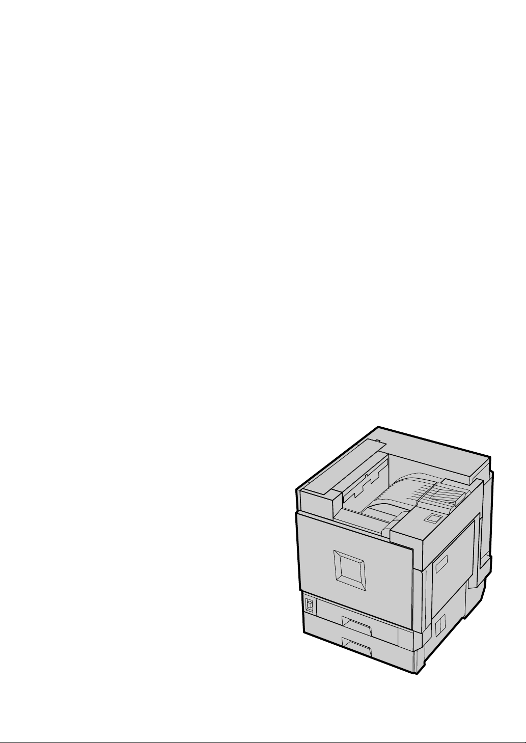
1. Getting Started
Features of this Printer
❖❖❖❖ High Productivity of 28 ppm in Full Color
This printer comes with a four-tandem engine which enables the high performance output of 28 ppm (pages per minute) in full color. You can print conference records, sales promotion ads, etc. in full color, as you would do with
a monochrome printer. The printer's monochrome speed of 38 ppm is equivalent to that of a high-speed monochrome laser printer, enabling you to use
this printer as your high performance network printer for both color and
monochrome printing.
❖❖❖❖ High Image Quality Output in True 1200 dpi
True 1200 dpi resolution makes it possible for this printer to output text documents, documents containing images that are read in with a digital camera
or scanner, and graphics in fine detail. This high resolution can be output at
the speed of 14 ppm.
❖❖❖❖ Versatile Options with the New Generation Controller
With the new high-speed, 64-bit controller architecture, optimized for Windows software, this printer can output at top speed. You can also use "Secure
Print", where the printer does not output unless a password is entered. This
printer answers the controller's needs that only a color printer can do.
❖❖❖❖ First-of-its-Class Finisher
The first-of-its-class Finisher
electronic sort printing, but also corresponds to post process printing. Highspeed Duplex Print, stapling, punching, etc. can be done. The work flow of color documents up until now can be vastly improved.
*1
Optional 2 Tray Finisher is required.
*2
Optional Duplex Unit is required.
*1
is not only compatible with Duplex Print
*2
and
1
Page 10
Getting Started
0
Guide to the Printer
1
Exterior: Front View
1
2
3
4
5
6
15
7
8
9
1
11
12
13
14
ZDJX701cJ
1. Upper Cover
Remove to install the optional 4-bin Mailbox.
2. Control Panel
Contains keys for printer operation and a
panel display that shows the printer status.
⇒ p.5 “Control Panel”
3. Front Cover
Open this cover when replacing the
Waste Toner Bottle, Development Unit or
Photoconductor Unit. A screwdriver is
attached to the front cover.
4. Power Switch
Use this switch to turn the power on and
off.
5. Tray 1
Loads up to 500 sheets of plain paper in
this tray for printing. Exclusive for A4 K
paper.
2
6. Tray 2
Loads up to 500 sheets of plain paper in
this tray for printing.
7. Standard Tray
Output is stacked here with the print side
down.
Note
❒ If printed A3 short-edge feed or 11×17
short-edge feed papers fall off the
standard tray, raise the fence to prevent them from falling.
Page 11
Guide to the Printer
6
7
8. Upper Right Cover
Open this cover to replace toner cartridge.
9. Ventilator
This hole helps to keep components inside the printer from overheating. Do not
block or obstruct the ventilator. A malfunction may occur due to overheating.
10. Parallel Port (IEEE 1284, ECP)
Use a parallel cable to connect the printer
to the host computer.
11. Ethernet Port
Use an network interface cable to connect
the printer to the network.
Exterior: Rear View
1
12. Bypass Tray Extension
Pull out this extension to load paper in
the bypass tray when its length is longer
than A4 L.
13. Bypass Tray
Use to print on thick paper, OHP transparencies, custom size paper, as well as
plain paper. Up to 100 sheets of plain paper can be loaded.
14. Ventilator
This hole helps to keep components inside the printer from overheating. Do not
block or obstruct the opening. A malfunction may occur due to overheating.
15. Right Cover
Open this cover to remove misfed paper.
1
2
3
4
5
1. Ventilator and Dustproof Filter
This hole helps to keep components inside the printer from overheating. Do not
block or obstruct the ventilator. A malfunction may occur due to overheating.
Remove the ventilator to replace the internal dustproof filter.
2. Connector
Connect the main power cable, cables
from options, etc. to the appropriate port.
3. Duplex Unit Port
Connect the cable for the Duplex Reversal Unit to this port.
8
ZDJX702J
4. 4-bin Mailbox/2 Tray Finisher
Port
Connect the cable for the 4-bin Mailbox
or the 2 Tray Finisher to this port.
5. Power Port
Connect the power cable to this port and
the other cable end to the wall outlet.
6. Upper Left Cover
Open this cover to remove misfed paper
or when replacing the Fusing Unit.
3
Page 12
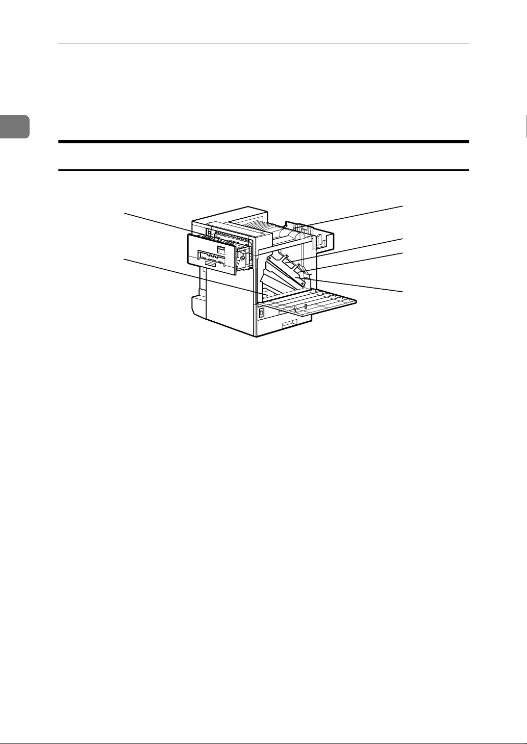
Getting Started
1
7. External Tray
Printed output is stacked here with the
print side up.
Inside
1
2
3
1. Fusing Unit
Fuses the image on paper.
When "Replace Fusing Unit (Type C)" ap-
pears on the panel display, replace this
unit.
2. Fuser Oil Unit
Attach to the Fusing Unit.
When "Replace Fuser Oil Unit (TypeG)"
appears on the panel display, replace this
unit.
3. Waste Toner Bottle
Collects toner that is wasted during
printing.
When "Replace Waste Toner (Type E)"
appears on the panel display, replace
with a new waste toner bottle.
4. Toner Cartridge
Loads from the printer rear in the order
of magenta (M), cyan (C), yellow (Y), and
black (K).
When "Add Toner: color" appears on the
panel display, replace the appropriate
toner cartridge.
8. Ventilators
These holes help to keep components inside the printer from overheating. Do not
block or obstruct the ventilators. A malfunction may occur due to overheating.
4
5
6
7
5. Photoconductor Unit
The printer comes with one black Photoconductor Unit and three color (yellow,
cyan, magenta) Photoconductor Units.
When "Replace Color PCU (Type A)" appears on the panel display, replace the
three color Photoconductor Units.
When "Replace Black PCU (Type F)" appears on the panel display, replace the
black Photoconductor Unit.
6. Development Unit
The printer comes with one black Development Unit and three color (yellow, cyan, magenta) Development Units.
When "Replace Color Dev. Unit(TypeB)"
appears on the panel display, replace the
three color Development Units.
When "Replace Black Dev. Unit(TypeD)"
appears on the panel display, replace the
black Development Unit.
7. Inner Cover
Open this cover when replacing the Photoconductor Unit or Development Unit.
4
Page 13
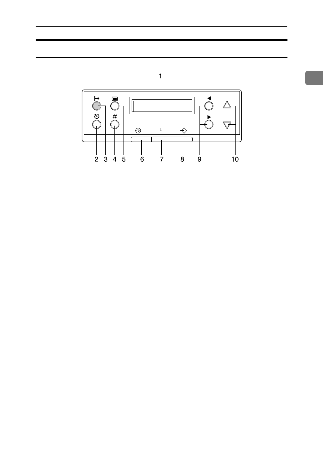
Control Panel
Guide to the Printer
1
1. Panel display
Shows the current status of the printer
and error messages.
{{{{Cancel}}}} key
2.
Press this key to return to the "Ready"
condition on the panel display.
When the printer is online, press this key
to cancel any ongoing print job.
3. {
{On Line}}}} key
{{
Indicates whether the printer is online or
offline.
Press this key to switch between online
and offline.
When the lamp is lit, the printer is online,
enabling data reception from the host
computer.
When the lamp is off, the printer is offline, disabling data reception from the
host computer.
Press this key to return to the ready condition.
4. {
{Enter}}}} key
{{
Press this key to execute menu items selected on the panel display.
Press this key to force the printer to print
the data received in the online status
when the paper size or type dose not
match with the actual set size or type.
5. {
{Menu}}}} key
{{
Press this key to make and check the current printer settings.
6. Power indicator
Power indicator is on while the power
switch is on. Power indicator is off when
the power is turned off or while the printer is in Energy Saver mode.
7. Error indicator
Blinks or lights up whenever any printer
error occurs. However, turns off in the
Energy Saver mode.
8. Data In indicator
Blinks while the printer is receiving data
from a computer. Data In indicator is on
if there is data to be printed.
9. {
}, {{{{VVVV}}}} keys
{{{WWWW}}}
The {{{{WWWW}}}} key advances the cursor in text
entry screens. The {{{{VVVV}}}} key backspaces or
deletes.
10. {
Use these keys to scroll a list of options
or, in text entry, scroll individual characters.
}, {{{{TTTT}}}} Keys
{{{UUUU}}}
5
Page 14

1
Getting Started
6
Page 15

2. Setting Up
R
R
Where to Put the Printer
The printer's location should be carefully chosen because environmental conditions greatly affect its performance.
WARNING:
• Confirm that the wall outlet is near the machine and freely accessi-
ble, so that in the event of an emergency, it can be easily unplugged.
• Only connect the machine to the power source described on this
sheet.
• Avoid multi-wiring.
• Do not damage, break or make any modifications to the power ca-
ble. Do not place heavy objects on it, pull it hard or bend it more
than necessary. These actions could damage the cable. A frayed or
damaged cable might cause an electrical and fire hazard.
CAUTION:
• Do not handle the plug with wet hands. Doing this might cause an elec-
trical shock.
• Keep the machine in an area that is within optimum environmental con-
ditions. Operating the machine in an environment that is outside the recommended ranges of humidity and temperature can cause an electrical
or fire hazard. Keep the area around the socket free of dust. Accumulated dust can become an electrical or fire hazard.
• Place the machine on a strong and level surface. Otherwise, the ma-
chine might fall and injure someone.
• If you use the machine in a confined space, confirm there is a continuous
air turnover.
7
Page 16
Setting Up
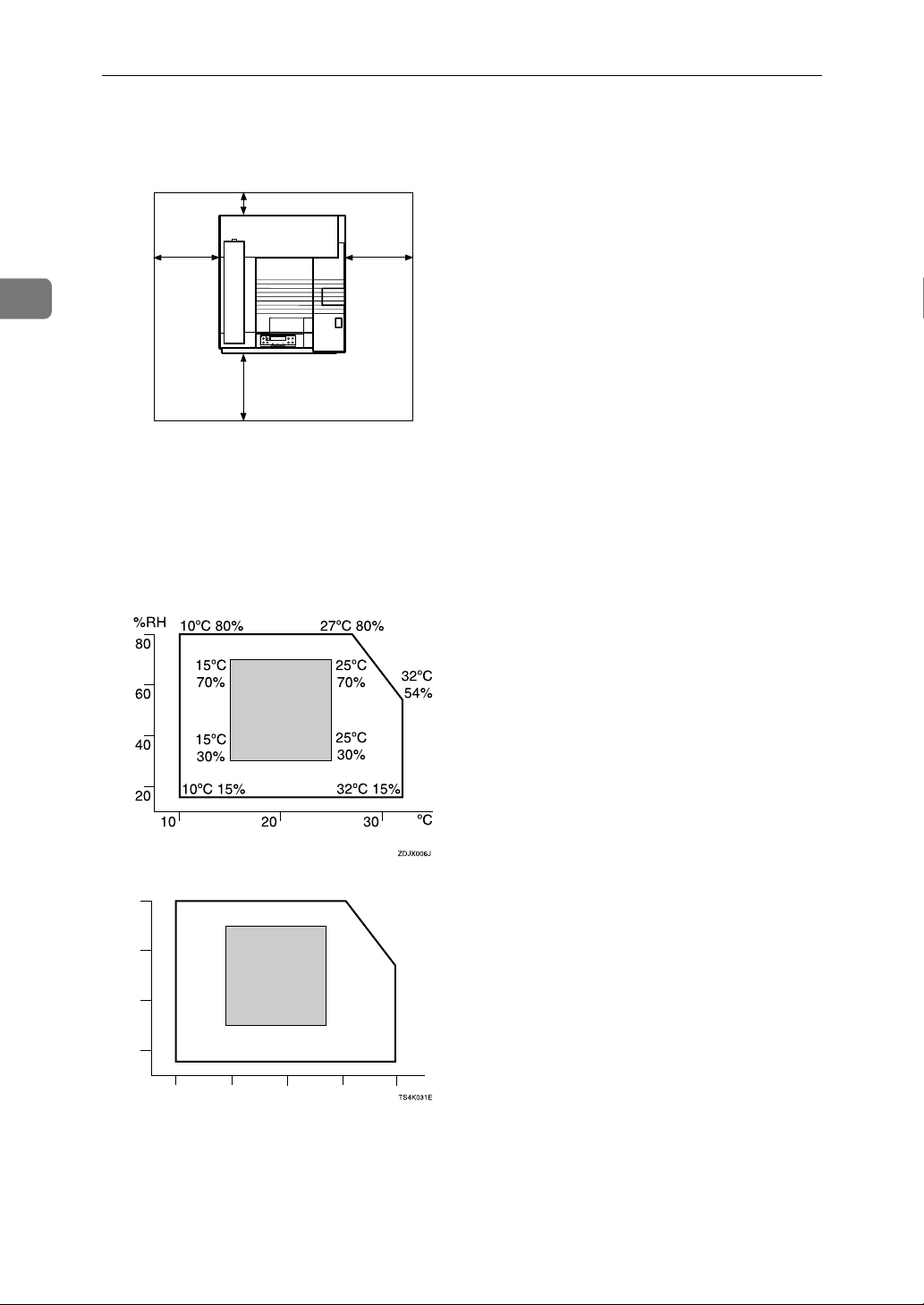
❖❖❖❖ Space Required for Installation
Leave enough space around the printer. This space is necessary to operate the
printer. The recommended (or minimum) space requirements are as follows:
B
2
A
D
C
ZDJX005J
A: 46 cm (19 inch) or more
B: 10 cm (4 inch) or more
C: 55 cm (22 inch) or more
D: 70 cm (28 inch) or more
❖❖❖❖ Optimum Environmental Conditions
Possible and recommended temperature and humidity ranges are as follows:
%RH
50°F 80%
80
60
40
20
59°F
70%
59°F
30%
50°F 15%
50 80 90
60 70
80.6°F 80%
77°F
70%
89.6°F
54%
77°F
30%
89.6°F 15%
°F
• White area: Possible operation Range
• Gray area: Recommended Range
8
Page 17

Where to Put the Printer
Note
❒ The machine must be level within 5 mm, 0.2" both front to rear and left to
right.
❒ To avoid possible build-up of ozone, locate this machine in a large well
ventilated room that has an air turnover of more than 30 m
❒ When you use this machine for a long time in a confined space without
good ventilation, you may detect an odd smell. To keep the workplace
comfortable, we recommend that you keep it well ventilated.
3
/hr/person.
❖❖❖❖ Environments to Avoid
Important
❒ Locations exposed to direct sunlight or strong light
❒ Dusty areas
❒ Areas with corrosive gases
❒ Areas excessively cold, hot, or humid
❒ Locations near an air conditioner or humidifier
❒ Locations near other electronic equipment
❒ Locations where the printer might be subjected to frequent strong vibra-
tion
2
❖❖❖❖ Power Source
Connect the power cable to a power source with the following specifications:
• 120 V, 60 Hz, 10 A or more
9
Page 18
2
Setting Up
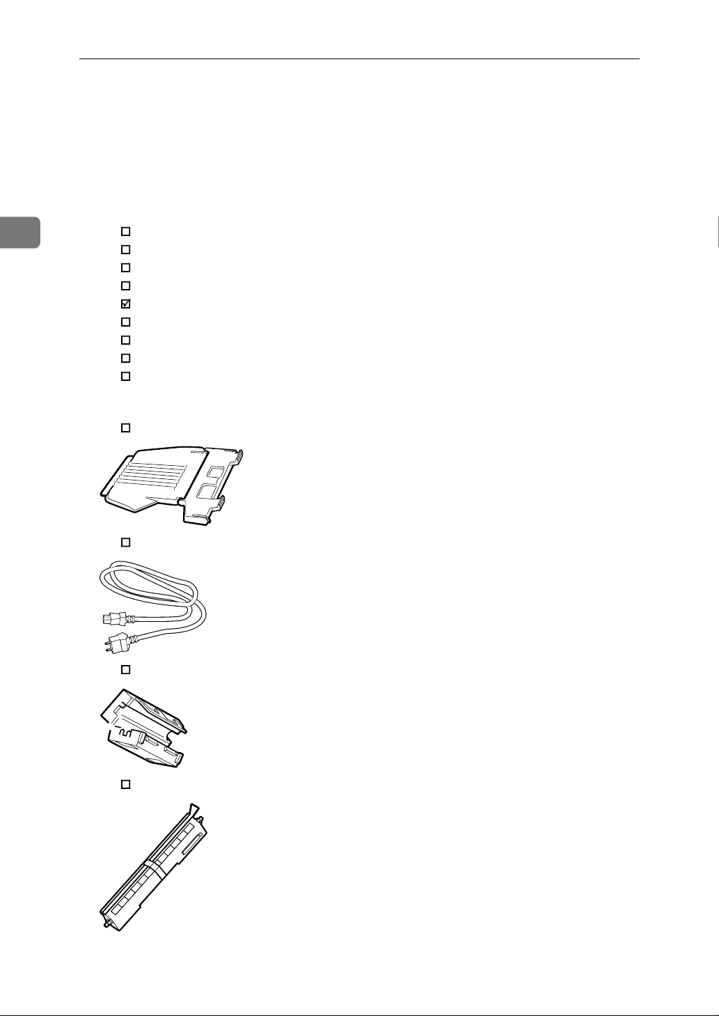
Checking the Contents of the Box
Check the contents of the box for the following items.
AAAA
For missing items, contact your sales or service representative.
❖❖❖❖ Manuals and CD-ROMs
Description form
Manuals for this Printer
Getting Started
Configuration Guide
Setup Guide (This manual)
Maintenance Guide
CD-ROM "Fiery 3850C User Software"
CD-ROM "Fiery 3850C Operating Instructions"
CD-ROM "Fiery 3850C Network Utilities"
❖❖❖❖ Parts
External Tray
Power Cable
Ferrite Core
Fuser Oil Unit
10
Page 19
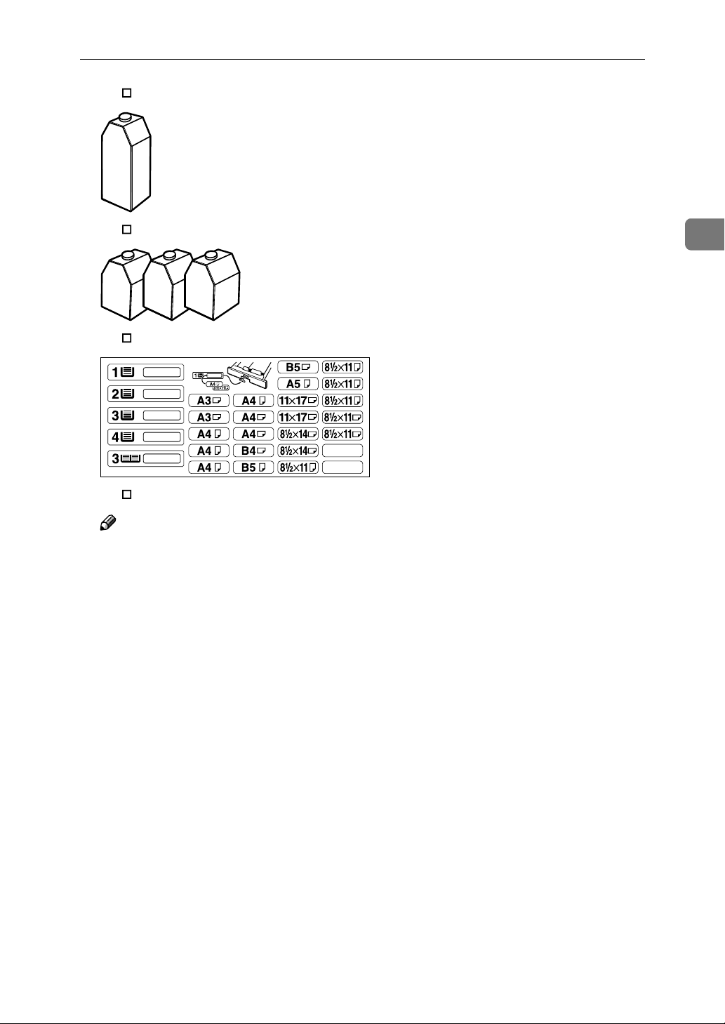
Black Toner Cartridge (K)
Checking the Contents of the Box
Magenta (M), Cyan (C), Yellow (Y) Toner Cartridges
Paper Feed Unit Labels
Additional Documentations
Note
❒ This package does not include an interface cable. Please purchase one for
use with your host computer.
2
11
Page 20
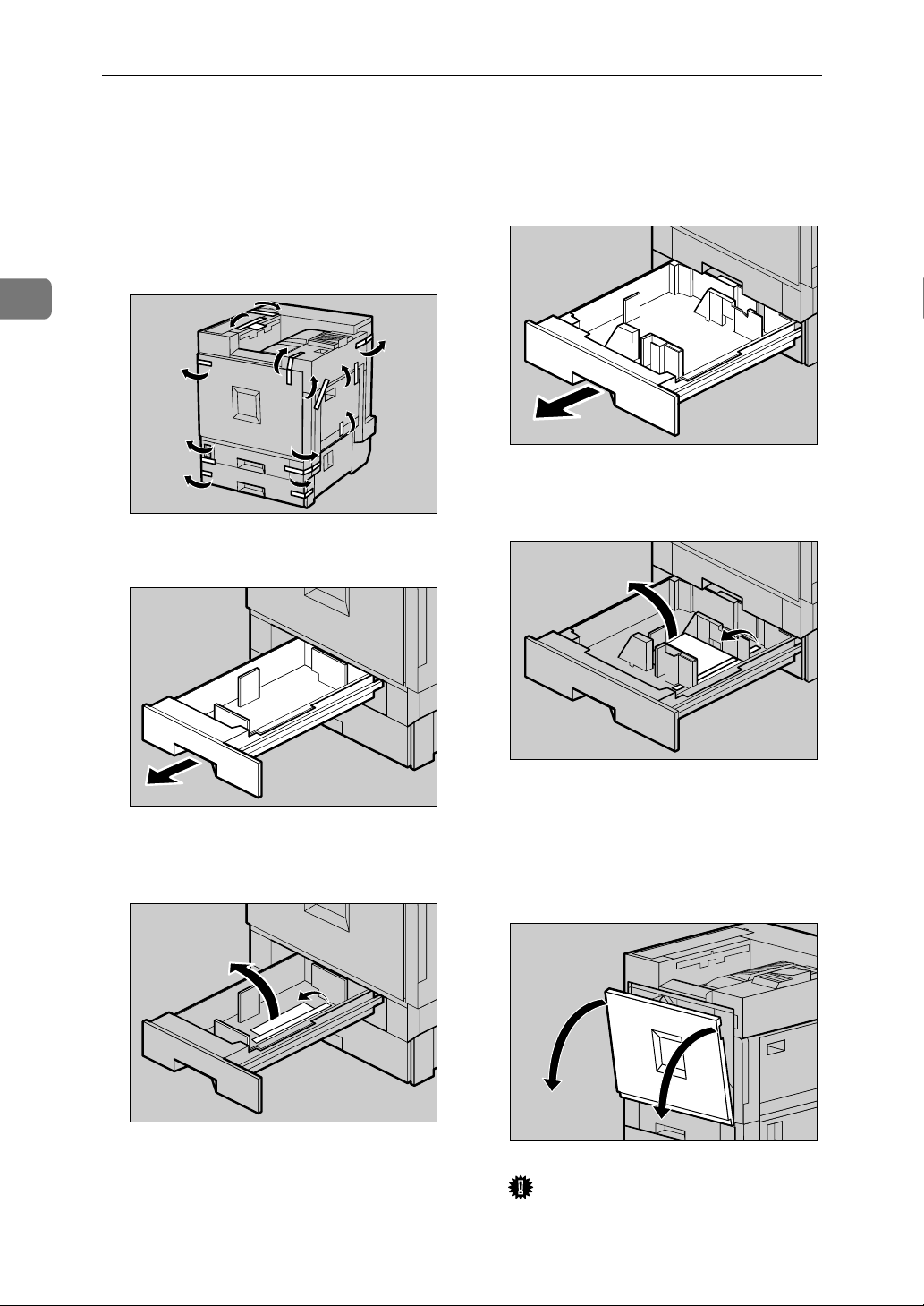
Setting Up
Unpacking the Printer
2
Remove the adhesive tape on the
AAAA
printer body. Remove the cardboard that is taped to the Standard Tray.
Open Tray 1.
BBBB
ZDJH001J
Open Tray 2.
EEEE
Remove the adhesive tape and
FFFF
sheet of paper.
ZDJH005J
12
Remove the adhesive tape and
CCCC
sheet of paper.
Close Tray 1 slowly.
DDDD
ZDJH003J
ZDJH004J
Close Tray 2 slowly.
GGGG
Open the front cover slowly by
HHHH
pulling down from the two areas
on the left and right.
Important
❒ Do not place objects on the
opened front cover.
ZDJH006J
ZDJH007J
Page 21
Unpacking the Printer
Remove the adhesive tape.
IIII
Remove the securing pin, as
JJJJ
shown in the illustration, from
the Transfer Unit. Pinch it, and
then pull it out.
ZDJH008J
Important
❒ Be sure to pull out all four piec-
es of tapes to avoid printer malfunction during operation.
❒ The removed tape is dirty. Be
careful not to let it touch your
hands or clothes.
Close the front cover slowly by
LLLL
pushing the two areas on the left
and right.
2
ZDJH041J
Pull out the four pieces of tapes
KKKK
coming out from the Development Unit slowly, in a level manner.
ZDJX450J
ZDJH702J
Put labels "1" and "2" on the front
MMMM
of the paper trays.
ZDJP129J
13
Page 22
Setting Up
Installing the Fuser Oil Unit
2
Install the Fuser Oil Unit to the Fusing
Unit.
Pull out the left cover slowly.
AAAA
ZDJH047J
Open the upper left cover.
BBBB
Important
❒ Do not touch any areas other
than the handle.
When replacing the fusing unit, do
not turn the blue dial at the side of
the new fusing unit until the power switch is turned on.
Put the removed Fusing Unit in a
DDDD
stable and level place.
Take out the Fuser Oil Unit from
EEEE
the bag, and remove seal (AAAA), and
then seal (BBBB) as shown in the illustration.
14
Holding the green handle, pull
CCCC
up the Fusing Unit slowly in the
direction as shown in the illustration.
ZDJH048J
ZDJH049J
ZDJH053J
Note
❒ Be sure to remove seal (A), and
then pull it out in a level manner.
Important
❒ Be sure to remove the seals to
avoid printer malfunction.
❒ Be sure to remove seal (A) first,
and then remove seal (B) to
avoid an oil leak.
❒ There is oil on the removed
seals. Be careful not to let them
come in contact with your
clothes.
❒ Be sure to put the Fusing Oil in
a stable and level place.
Page 23
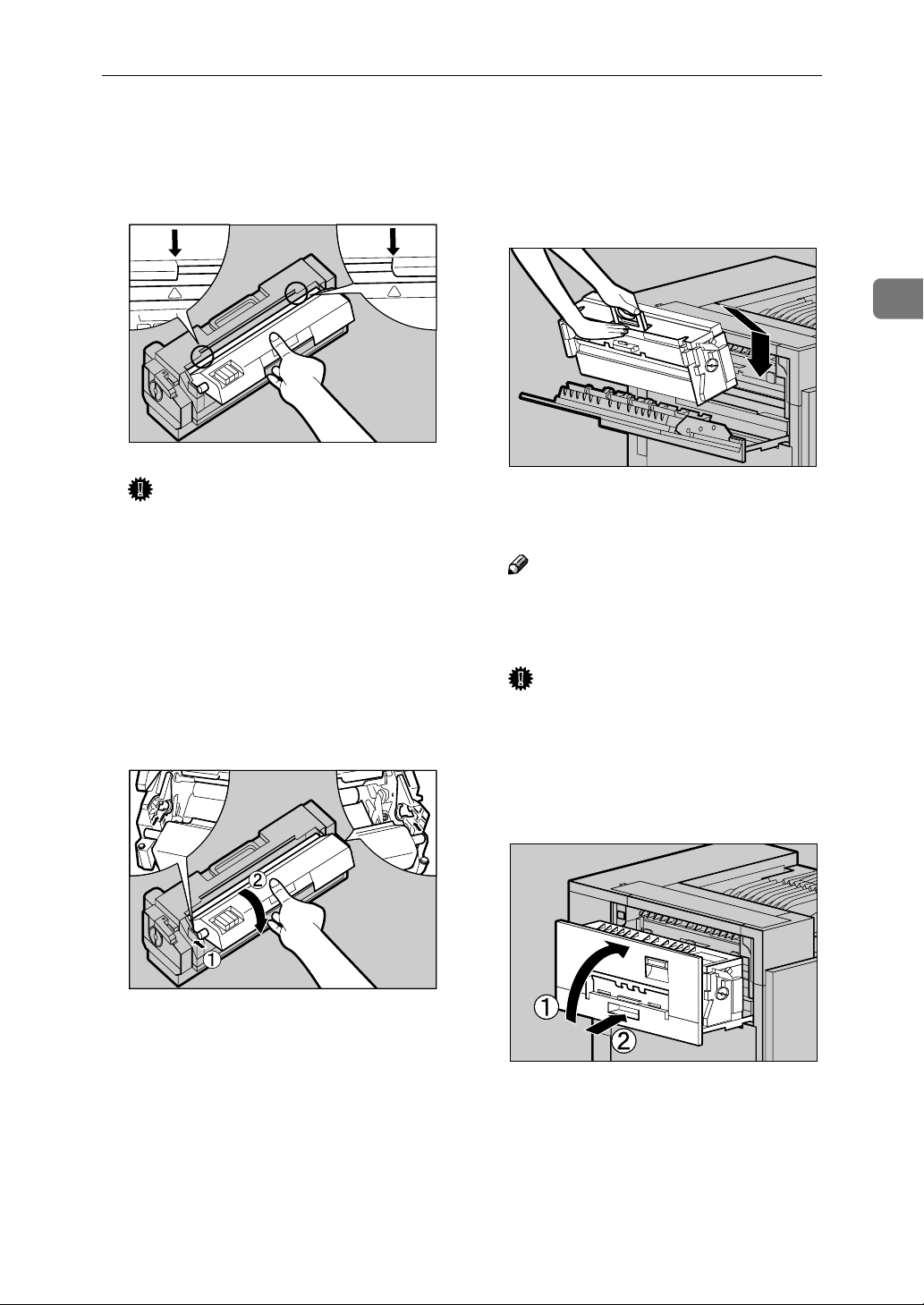
Installing the Fuser Oil Unit
Match (UUUU) on the front of the Fus-
FFFF
er Oil Unit and the arrow on the
Fusing Unit as shown in the illustration.
Important
❒ Be careful not to get oil on the
metal part of the left side of the
Fuser Oil Unit.
Insert the left and right protru-
GGGG
sions of the Fuser Oil Unit into
the white holders of the Fusing
Unit (AAAA), and then move the Fuser Oil Unit in the direction shown
by the arrow (BBBB) to attach the Fuser Oil Unit to the Fusing Unit.
ZDJH055J
Holding the green handle with
HHHH
one hand, use your other hand to
push the front area of the handle
to a slight slant, and then push the
Fusing Unit slowly to the back.
Confirm that the Fusing Unit is set
to the printer vertically.
Note
❒ Confirm that the Fuser Oil Unit
is facing the inside of the printer.
Important
❒ Confirm that the Fusing Unit is
in appropriate position.
Close the upper left cover (AAAA) and
IIII
push the handle (BBBB) slowly to the
back until it clicks.
2
ZDJH050E
ZDJH054J
ZDJH051J
15
Page 24
2
Setting Up
Attach the External Tray to the
JJJJ
printer. Insert the hooks of the External Tray into the printer slits,
and then lower it toward you.
ZDJH010J
16
Page 25

Installing Options
R
Installing Options
CAUTION:
• Before installing options, the machine should be turned off and unplugged
for at least an hour. Components inside the machine become very hot, and
can cause a burn if touched.
• Before moving the machine, unplug the power cable from the outlet. If the
cable is unplugged abruptly, it could become damaged. Damaged plugs or
cables can cause an electrical or fire hazard.
• When lifting the machine, use the grips on both sides. The machine could
break or cause an injury if dropped.
By installing options, you can improve the printer performance and have an expanded variety of features to use.
Important
❒ Rating voltage of the connector for options: Max. DC 24 V.
When installing multiple options on the printer, we recommend the following
order of installation.
❖❖❖❖ Flow of Option Installation
A
Install the 500, 1000-sheet Paper
Feed Unit, or 2000-sheet Large
Capacity Tray.
(PAPER FEED UNIT Type
3800C, Paper Bank PS 470)
T
Install the Paper Feed Unit to the bottom of the printer.
You can choose to install the PAPER FEED UNIT Type
3800C (500 × 1), Type 3800C (500 × 2) or Paper Bank PS470.
If you install the Paper Bank PS470, you can load up to 3,100
sheets of paper at once.
2
B
Install the Duplex Unit.
(Duplex Unit Type 3800C)
T
C
Install the 2 Tray Finisher.
(SR770)
T
D
Install the 4-bin Mailbox.
(Mail Bin Type 3800C)
Attach the Duplex Reversal Unit to the left side of the printer, and the Duplex Feed Unit inside the printer.
Attach the SR770 to the left side of the printer.
You cannot install the SR770 unless both the Paper Feed
Unit and Duplex Unit options are installed.
If you choose to install the 4-bin Mailbox, you cannot install
the SR770.
Remove the upper cover to install Mail Bin Type 3800C.
If you choose to install the 2 Tray Finisher, you cannot install the 4-bin Mailbox.
Install options in the positions as shown in the illustration.
17
Page 26
2
Setting Up
❖❖❖❖ Exterior
1. PAPER FEED UNIT Type 3800C
(500 ×××× 1)
Loads up to 500 sheets (500 sheets × 1
column) of paper.
⇒
p.20 “Installing the PAPER FEED
UNIT Type 3800C (500 x 1)”
2. PAPER FEED UNIT Type 3800C
(500 ×××× 2)
Loads up to 1,000 sheets (500 sheets
2 columns) of paper.
⇒
p.23 “Installing the PAPER FEED
UNIT Type 3800C (500 x 2)”
3. Paper Bank PS470 (2000-sheet
Large Capacity Tray)
Loads up to 2,000 sheets (2,000 sheets
×
1 column) of paper.
⇒
p.25 “Installing the Paper Bank
PS470 (2000-sheet Large Capacity
Tray)”
4. SR770 (2 Tray Finisher)
Performs Job Separation, staples and
punches holes. Install the Finisher on
the left side of the printer.
⇒
p.34 “Installing the SR770 (2 Tray
Finisher)”
5. Mail Bin Type 3800C (4-bin Mail-
box)
×
Sorts printed documents from multiple users. Attach the Mailbox to the
top of the printer.
⇒
p.40 “Installing the Mail Bin Type
3800C (4-bin Mailbox)”
6. Duplex Reversal Unit
Flips over the paper during duplex
printing. Install the unit on the left
side of the printer.
⇒
p.30 “Installing the Duplex Rever-
sal Unit”
ZDJP001J
18
Page 27
Installing Options
7. Duplex Feed Unit
Transports the paper during duplex
printing. Install the unit inside the
printer.
⇒ p.30 “Installing the Duplex Rever-
sal Unit”
Important
❒ You cannot install the 2 Tray Finisher unless both the Paper Feed Unit and
Duplex Unit options are installed.
❒ You cannot install both the 2 Tray Finisher and 4-bin Mailbox at the same
time.
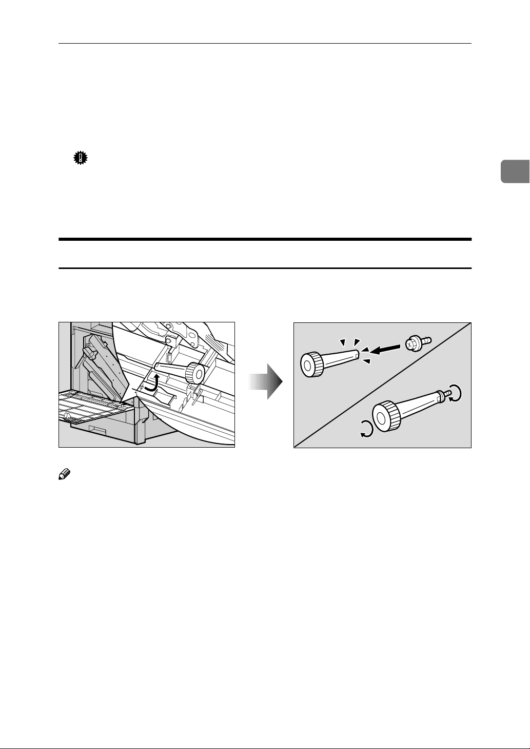
How to Use the Screwdriver
The exclusive screwdriver used for attaching options is attached to the inside of
the front cover. By pushing the screw top into the screwdriver, you can work
without having to worry about dropping the screw.
2
ZDJP003J
Note
❒ After using the screwdriver, return it to its original position on the inside of
the front cover.
19
Page 28
Setting Up
R
R
2
Installing the Paper Feed Unit
Preparation
If you want to use the optional Duplex Unit, 2 Tray Finisher or 4-bin
Mailbox at the same time, install
the optional Paper Feed Unit first,
and then install these options.
If you have already installed the
optional Duplex Unit, 2 Tray Finisher and 4-bin Mailbox, remove
all these options before installing
the optional Paper Feed Unit.
Important
❒ Before installation, check the ori-
entation of the Paper Feed Unit or
2000-sheet Large Capacity Tray
you want to place.
❒ When installing multiple options,
install the Paper Feed Unit first.
❒ Four persons are needed to install
the Paper Feed Unit. Start the installation work after all four persons are ready.
CAUTION:
• When moving the machine, each
person should hold the handle,
where two are located on opposite sides, and lift slowly. Lifting it
carelessly or dropping it may
cause an injury.
Installing the PAPER FEED UNIT Type
3800C (500 x 1)
Preparation
If you want to use the optional Duplex Unit, 2 Tray Finisher or 4-bin
Mailbox at the same time, install
the optional Paper Feed Unit first,
and then install these options.
If you have already installed the
optional Duplex Unit, 2 Tray Finisher and 4-bin Mailbox, remove
all these options before installing
the optional Paper Feed Unit.
Important
❒ Before installation, check the ori-
entation of the Paper Feed Unit
you want to place.
❒ When installing multiple options,
install the Paper Feed Unit first.
CAUTION:
• When moving the Paper Feed
Unit, hold the bottom of both
sides, and lift slowly. Lifting it
carelessly or dropping it may
cause an injury.
Note
❒ The 500-sheet Paper Feed Unit
weights approximately 18 kg (39.7
lbs).
Note
❒ The printer weights approximately
83 kg (183 lbs).
20
Turn off the power switch and
AAAA
unplug the power cable.
Remove the adhesive tape.
BBBB
ZDJP004J
Page 29
Installing Options
Adjust the four corners of the
CCCC
printer to those of the 500-sheet
Paper Feed Unit, and then lower
the printer slowly into place.
Important
❒ Four persons should hold the
handles, located on two sides of
the printer, to move it.
ZDJP006J
Take out the packaged items,
EEEE
making sure there are two thumb
screws and one mounting bracket. Close the tray of the 500-sheet
Paper Feed Unit tightly.
Pull out Tray 2 slowly while lift-
FFFF
ing it up a little.
2
ZDJP005J
Open the tray of the 500-sheet Pa-
DDDD
per Feed Unit.
A Remove the adhesive tape and
sheet of paper.
B Remove the adhesive tape and
the corrugated paper inside the
tray as shown in the illustration.
ZDJP007J
ZDJX801J
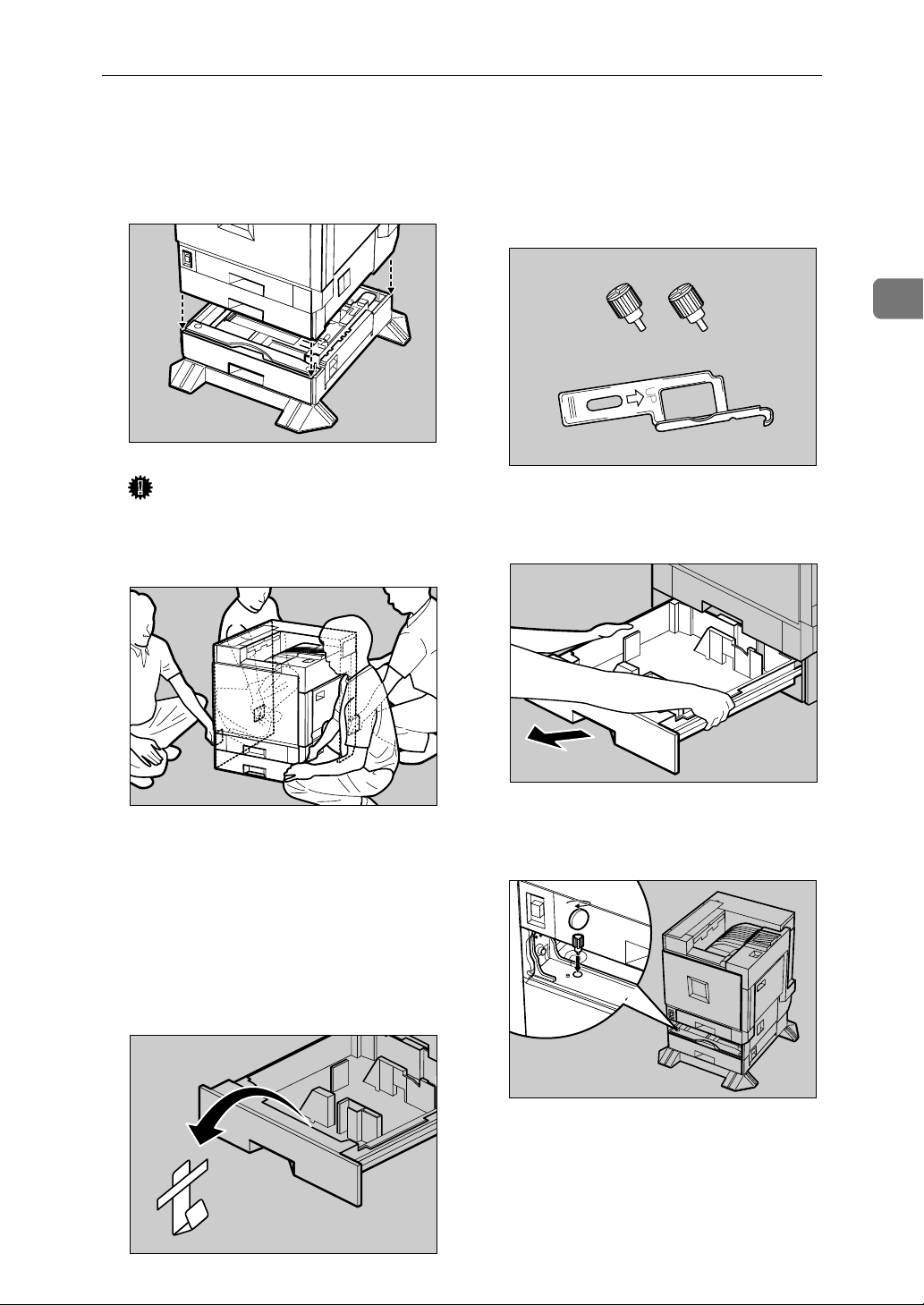
Fasten one thumb screw. Use a
GGGG
coin to fasten it tightly.
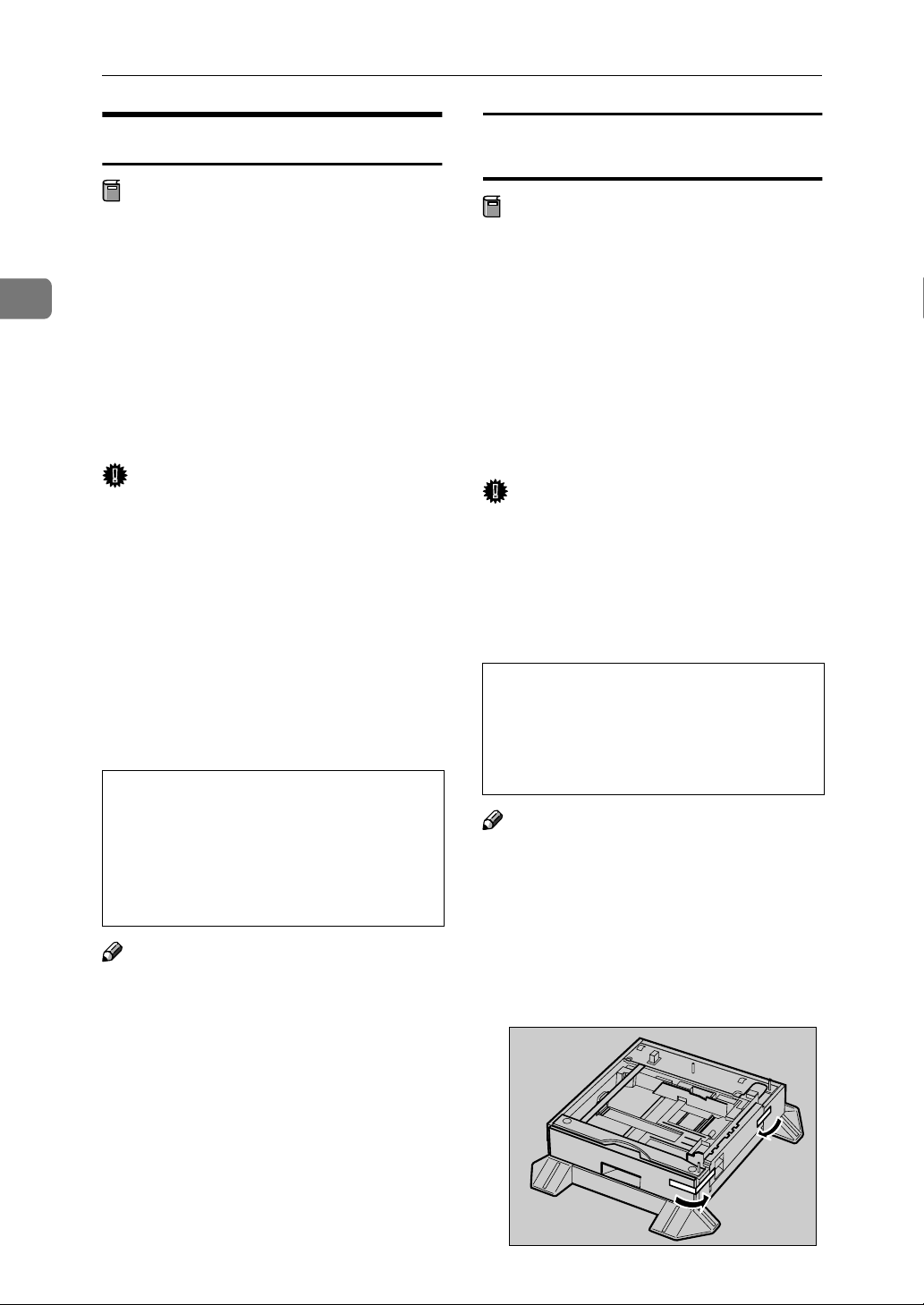
Slide Tray 2 back into the printer
HHHH
slowly until it stops.
ZDJP008J
ZDJP009J
21
Page 30
Setting Up
2
Open the right cover of the 500-
IIII
sheet Paper Feed Unit.
Hook the mounting bracket to the
JJJJ
hole as shown in the illustration.
ZDJP010J
Stick label "3" above the handle
MMMM
on the front of the 500-sheet Paper
Feed Unit.
Note
❒ After finishing all installation
for printing, you can check
whether the 500-sheet Paper
Feed Unit is installed properly.
Print the Configuration Page
from the "Print Menu" menu. If
it is installed properly, you will
see "Tray 3" under the "Paper
Tray Information" list.
ZDJP126J
Fasten the bracket with the other
KKKK
thumb screw. Use a coin to fasten
it tightly.
Close the right cover of the 500-
LLLL
sheet Paper Feed Unit.
ZDJP011J
ZDJP012J
❒ If the Paper Feed Unit is not in-
stalled properly, reinstall from
step
properly even after reinstallation, contact your sales or service representative.
Reference
⇒ p.55 “Printing the Configura-
tion Page”.
. If you cannot install it
A
22
Page 31

Installing the PAPER FEED UNIT Type
R
3800C (500 x 2)
Preparation
If you want to use the optional Duplex Unit, 2 Tray Finisher or 4-bin
Mailbox at the same time, install
the optional Paper Feed Unit first,
and then install these options.
Remove the adhesive tape.
BBBB
Installing Options
2
If you have already installed the
optional Duplex Unit, 2 Tray Finisher and 4-bin Mailbox, remove
all these options before installing
the optional Paper Feed Unit.
Important
❒ Before installation, check the ori-
entation of the Paper Feed Unit
you want to place.
❒ When installing multiple options,
install the Paper Feed Unit first.
CAUTION:
• When moving the Paper Feed
Unit, hold the bottom of both
sides, and lift slowly. Lifting it
carelessly or dropping it may
cause an injury.
Note
❒ The 1000-sheet Paper Feed Unit
weights approximately 25 kg (55.2
lbs).
Adjust the four corners of the
CCCC
printer to those of the 1000-sheet
Paper Feed Unit, and then lower
the printer slowly into place.
Important
❒ Four persons should hold the
handles, located on two sides of
the printer, to move it.
ZDJP013J
ZDJP014J
Turn off the power switch and
AAAA
unplug the power cable.
ZDJP007J
23
Page 32

Setting Up
2
Open the tray of the 1000-sheet
DDDD
Paper Feed Unit.
A Remove the adhesive tape and
sheet of paper.
B Remove the adhesive tape and
the corrugated paper inside the
tray as shown in the illustration.
Take out the packaged items,
EEEE
making sure there are two thumb
screws and one mounting bracket. Close the tray of the 1000-sheet
Paper Feed Unit tightly.
ZDJX801J
Fasten one thumb screw. Use a
GGGG
coin to fasten it tightly.
Slide Tray 2 back into the printer
HHHH
slowly until it stops.
Open the right cover of the 1000-
IIII
sheet Paper Feed Unit.
ZDJP015J
24
Pull out Tray 2 slowly while lift-
FFFF
ing it up a little.
ZDJP005J
ZDJP008J
Hook the mounting bracket to the
JJJJ
hole as shown in the illustration.
ZDJP016J
ZDJP017J
Page 33

Installing Options
R
Fasten the bracket with the other
KKKK
thumb screw. Use a coin to fasten
it tightly.
Close the right cover of the 1000-
LLLL
sheet Paper Feed Unit.
Stick labels "3" and "4" above the
MMMM
handles on the front of the 1000sheet Paper Feed Unit.
ZDJP018J
Reference
⇒ p.55 “Printing the Configura-
tion Page”.
Installing the Paper Bank PS470 (2000sheet Large Capacity Tray)
Preparation
If you want to use the optional Duplex Unit, 2 Tray Finisher or 4-bin
Mailbox at the same time, install
the optional 2000-sheet Large Capacity Tray first, and then install
these options.
If you have already installed the
optional Duplex Unit, 2 Tray Finisher and 4-bin Mailbox, remove
all these options before installing
the optional 2000-sheet Large Capacity Tray.
Important
❒ Before installation, check the ori-
entation of the 2000-sheet Large
Capacity Tray you want to place.
2
ZDJP127J
Note
❒ After finishing all installation
for printing, you can check
whether the 1000-sheet Paper
Feed Unit is installed properly.
Print the Configuration Page
from the "Print Menu" menu. If
it is installed properly, you will
see "Tray 3, Tray 4" under the
"Paper Tray Information" list.
❒ If the Paper Feed Unit is not in-
stalled properly, reinstall from
step
properly even after reinstallation, contact your sales or service representative.
. If you cannot install it
A
❒ When installing multiple options,
install the Paper Feed Unit first.
CAUTION:
• When moving the Paper Feed
Unit, hold the bottom of both
sides, and lift slowly. Lifting it
carelessly or dropping it may
cause an injury.
Note
❒ The 2000-sheet Large Capacity
Tray weights approximately 25 kg
(55.2 lbs).
Turn off the power switch and
AAAA
unplug the power cable.
25
Page 34

Setting Up
2
Remove the adhesive tape.
BBBB
Adjust the four corners of the
CCCC
printer to those of the 2000-sheet
Large Capacity Tray, and then
lower the printer slowly into
place.
ZDJP019J
Take out the packaged items,
DDDD
making sure there are two thumb
screws and one mounting bracket. Close the tray of the 2000-sheet
Large Capacity Tray tightly.
Pull out Tray 2 slowly while lift-
EEEE
ing it up a little.
ZDJP005J
26
ZDJP020J
Important
❒ Four persons should hold the
handles, located on two sides of
the printer, to move it.
ZDJP007J
Fasten one thumb screw. Use a
FFFF
coin to fasten it tightly.
Slide Tray 2 back into the printer
GGGG
slowly until it stops.
ZDJP008J
ZDJP021J
Page 35

Installing Options
Open the right cover of the 2000-
HHHH
sheet Large Capacity Tray.
Hook the mounting bracket to the
IIII
hole as shown in the illustration.
ZDJP022J
Stick label "3" above the handle
LLLL
on the front of the 2000-sheet
Large Capacity Tray.
Note
❒ After finishing all installation
for printing, you can check
whether the 2000-sheet Large
Capacity Tray is installed properly. Print the Configuration
Page from the "Print Menu"
menu. If it is installed properly,
you will see "LCT" under the
"Paper Tray Information" list.
2
ZDJP128J
Fasten the bracket with the other
JJJJ
thumb screw. Use a coin to fasten
it tightly.
Close the right cover of the 2000-
KKKK
sheet Large Capacity Tray.
ZDJP023J
ZDJP024J
❒ If the Paper Feed Unit is not in-
stalled properly, reinstall from
step
properly even after reinstallation, contact your sales or service representative.
Reference
⇒ p.55 “Printing the Configura-
tion Page”.
. If you cannot install it
A
27
Page 36

2
R
R
Setting Up
Installing the Duplex Unit Type
3800C
Preparation
If you want to use the optional Paper
Feed Unit at the same time, install
the optional Paper Feed Unit first,
and then install the Duplex Unit.
CAUTION:
• The inside of the machine becomes very hot. Do not touch the
parts with a label indicating a
"hot surface". Touching a "hot
surface" could result in a burn.
CAUTION:
• Do not let go of the Duplex Reversal Unit until it is fastened in
place. It could drop and cause an
injury.
Installing the Duplex Reversal Unit Stand
Check the contents of the box.
AAAA
❖❖❖❖ Stand
❖❖❖❖ Duplex Reversal Unit
❖❖❖❖ Duplex Feed Unit
Remove the adhesive tape and
BBBB
packing materials.
Important
❒ Do not remove the adhesive
tape which hold the auxiliary
bar at this point. Remove it in
step
Duplex Reversal Unit”
❒ Do not remove the adhesive
tape which hold the cable of the
Duplex Reversal Unit at this
point. Remove it in step
p.30 “Installing the Duplex Reversal Unit”
on p.30 “Installing the
C
G
on
28
❖❖❖❖ Paper Guide
ZDJP711J
❖❖❖❖ One Short Screw, Four Long Screws
ZDJP712J
Page 37

Installing Options
Turn off the power switch and
CCCC
unplug the power cable from the
wall outlet.
Lift the External Tray in the direc-
DDDD
tion of the arrow (AAAA) and remove
(BBBB).
Remove the two small covers on
EEEE
the upper left cover of the printer.
A Open the upper left cover.
ZDJP038J
C Close the upper left cover.
Note
❒ You will not use the removed
two covers.
Remove the protective cover on
FFFF
the left side of the printer. Hold
the protective cover by both sides,
and while pushing the left side of
the cover (AAAA), open it in the direction of the arrow (BBBB), and then remove (CCCC).
2
ZDJP041J
ZDJP039J
B Pinch the two small covers and
pull in the direction of the arrow to remove them.
ZDJP040J
Note
❒ You will not use the removed
protective cover.
Attach the paper guide to the
GGGG
stand. Hold the paper guide so
that its right side bends down as
shown in the illustration, and
while holding it lightly (AAAA), insert it into the holes of the stand
(BBBB).
ZDJP042J
29
Page 38

2
Setting Up
Insert the claws of the stand into
HHHH
the holes on the left side of the
printer (AAAA), and push down (BBBB).
Tighten four long screws to fasten
IIII
the Duplex Reversal Unit Stand
using provided screwdriver. Fasten in the order of AAAA⇒⇒⇒⇒BBBB⇒⇒⇒⇒CCCC⇒⇒⇒⇒DDDD
as shown in the illustration.
ZDJP043J
Installing the Duplex Reversal Unit
Holding the Duplex Reversal
AAAA
Unit in a level position with both
hands, insert the hooks into the
groove of the stand. At this point,
adjust the tip of the hooks to the
line on the stand (AAAA) and insert
slowly (BBBB). Do not let go of the
Duplex Reversal Unit even after
insertion.
ZDJP044J
Reference
See p.19 “How to Use the
Screwdriver”.
This completes the installation of
the stand. Next, install the Duplex
Reversal Unit.
The hooks of the Duplex Reversal
Unit grasp the bar inside the
groove of the stand.
Supporting the Duplex Reversal
BBBB
Unit, remove the stopper of the
mounting bracket on the printer.
This stopper will be used in a later
step
, so be careful not to lose it.
E
ZDJP045J
ZDJP046J
30
Page 39

Installing Options
Supporting the Duplex Reversal
CCCC
Unit, remove the adhesive tape
and hold the auxiliary bar in front
of the hook on the left side, and
then stand it up.
Hook the hole of the auxiliary bar
DDDD
on the mounting bracket of the
printer.
ZDJP047J
Hang the auxiliary bar on the deep
EEEE
left end as shown in the illustration, and then install the stopper
that was removed in step
Make sure the auxiliary bar and
stopper are installed in the positions shown in the illustration.
Raise the Duplex Reversal Unit
FFFF
slowly, and then adhere it to the
printer.
.
BBBB
2
ZDJP049J
ZDJP048J
In step
the position shown with a perforated line in the illustration.
, move the auxiliary bar to
E
ZDJP050J
31
Page 40

Setting Up
2
Remove the adhesive tape which
GGGG
hold the cable, and then connect
the cable of the Duplex Reversal
Unit to the upper connector on the
back of the printer.
This completes the installation of
the Duplex Reversal Unit. Install
the Duplex Feed Unit after installing the External Tray.
Install the External Tray.
HHHH
A Stand the External Tray and in-
sert it from the left side with
both hands.
ZDJP051J
B Pushing the right edge of the
External Tray lightly with your
finger (AAAA), insert it (BBBB).
ZDJP053J
C Lower the External Tray to-
ward you.
ZDJP054J
32
ZDJP052J
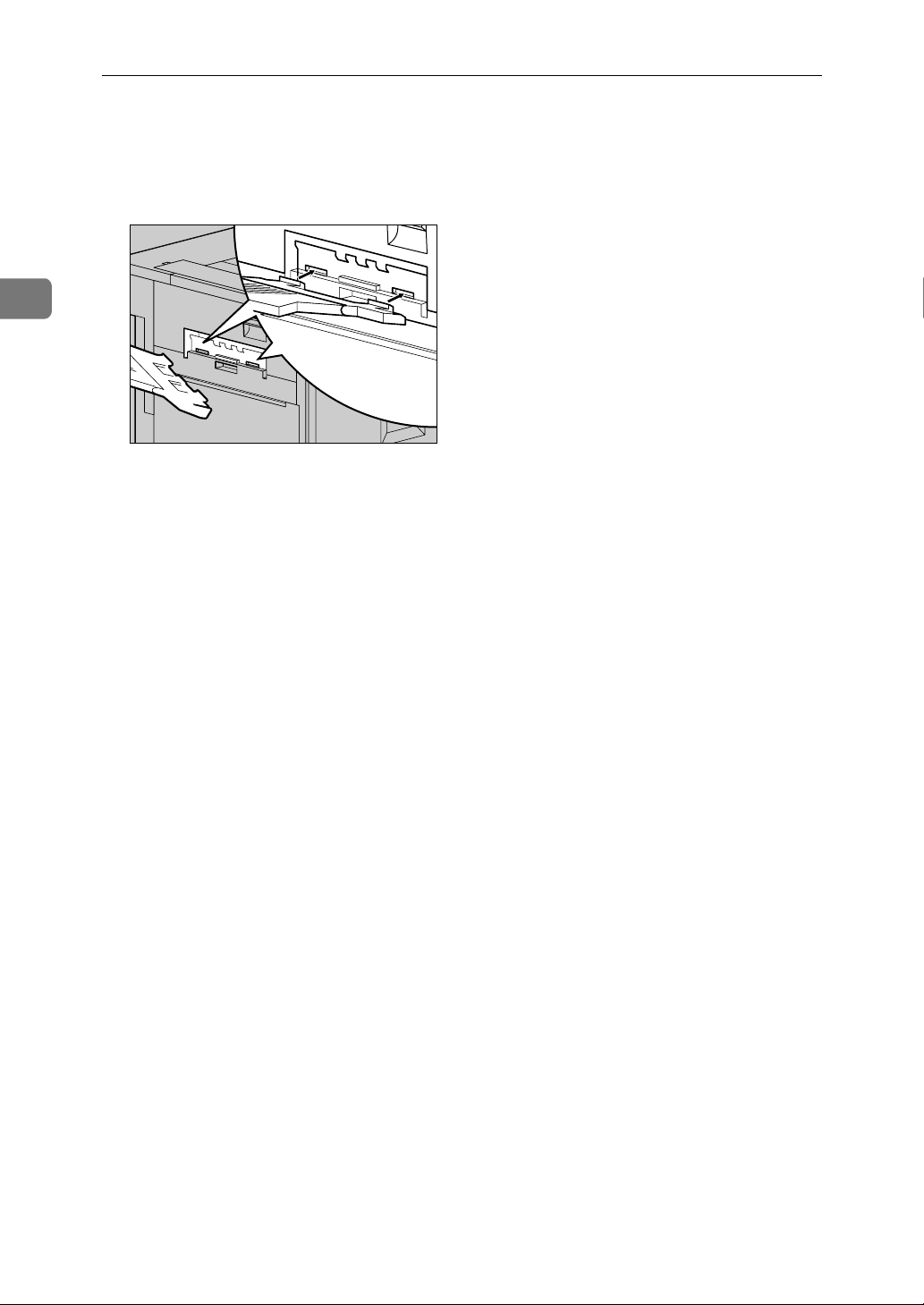
Installing the Duplex Feed Unit
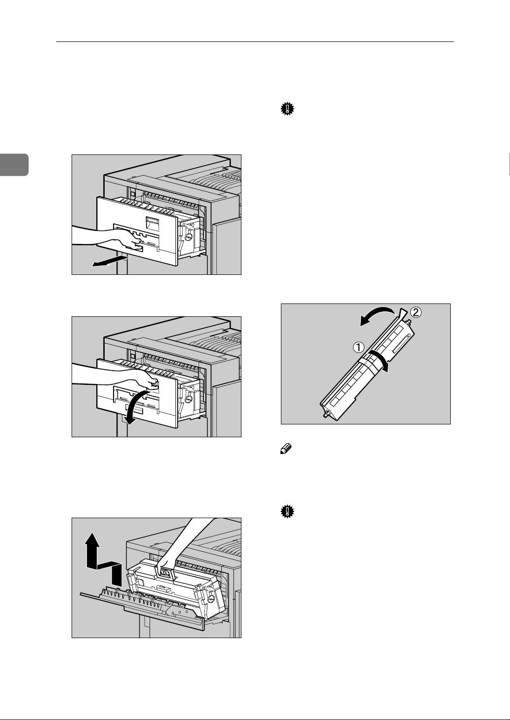
Open the front cover slowly by
AAAA
pulling the two points on the left
and right.
ZDJH007J
Page 41

Installing Options
Holding the Duplex Feed Unit
BBBB
with both hands, place it on the
vertical rail and insert slowly until it stops.
The vertical rail is in the position as
shown in the illustration.
ZDJP056J
Note
❒ Be sure to return the provided
screwdriver to its original position on the inside of the front
cover.
This completes the installation of
the Duplex Feed Unit.
Close the front cover slowly by
DDDD
pressing the two points on the left
and right.
2
ZDJH041J
Fasten the Duplex Feed Unit with
CCCC
one short screw using provided
screwdriver.
ZDJP133J
ZDJP057J
Note
❒ After finishing all installation
for printing, you can check
whether the Duplex Unit is installed properly. Print the Configuration Page from the "Print
Menu" menu. If it is installed
properly, you will see "Duplex
Unit" under the "Installed Options" list.
❒ If the Duplex Unit is not in-
stalled properly, reinstall from
step
⇒ p.28. If you cannot in-
A
stall it properly even after reinstallation, contact your sales or
service representative.
Reference
See p.55 “Printing the Configuration Page”.
33
Page 42

Setting Up
R
2
Check for spare parts. You will
EEEE
not use these spare parts.
Installing the SR770 (2 Tray
Finisher)
Preparation
Install the optional Paper Feed
Unit first, and then install the 2
Tray Finisher.
ZDJP058J
Remove the adhesive tape and
BBBB
packing materials.
Important
❒ Do not remove the adhesive
tape which hold the cable at this
point. Remove it in step
R
❖❖❖❖ Front and Side
.
ZDJP059J
CAUTION:
• When moving the 2 Tray Finisher, hold the center of both sides,
and lift slowly. Lifting it carelessly
or dropping it may cause an injury.
Note
❒ The 2 Tray Finisher weighs ap-
proximately 53 kg (116.9 lbs).
Important
❒ You cannot install the 2 Tray Fin-
isher unless both the Paper Feed
Unit and Duplex Unit options are
installed.
❒ You cannot install the 4-bin Mail-
box and 2 Tray Finisher at the same
time.
Turn off the power switch and
AAAA
unplug the power cable.
ZDJP062J
34
Page 43

Installing Options
❖❖❖❖ Back
❖❖❖❖ Connecting Bracket
❖❖❖❖ Mounting Bracket
2
ZDJP950J
❖❖❖❖ Rail
❖❖❖❖ Two 2 Tray Finisher Trays
ZDJP060J
❖❖❖❖ Interior
Check the contents of the box.
CCCC
❖❖❖❖ Two short screws, six long screws
ZDJP061J
Stand the External Tray of the
DDDD
printer.
A Stand it vertically.
ZDJP064J
35
Page 44

Setting Up
2
B Fold it into printer.
Insert the rail with a wheel in the
EEEE
mounting bracket.
ZDJP065J
Insert the rail, assembled in step
GGGG
, into the bottom area of the
EEEE
printer.
Hook the hole of the mounting
HHHH
bracket on the screw that was
temporarily fastened in step
ZDJP068J
.
FFFF
Temporarily fasten one long
FFFF
screw in the position shown in
the illustration. Turn the screw
three to four times using your
hand.
ZDJP066J
ZDJP067J
Holding the mounting bracket
IIII
with both hands, move it in the
direction of up (AAAA) ⇒⇒⇒⇒ right (BBBB).
ZDJP069J
ZDJP070J
36
Page 45

Installing Options
With the left corner of the mount-
JJJJ
ing bracket adjusted to the position shown by the arrow in the
illustration, fasten the left side of
the mounting bracket with a long
screw using provided screwdriver. Also tighten the screw on the
right side that was temporarily
fastened in step
Reference
See p.19 “How to Use the
Screwdriver”.
.
FFFF
ZDJP071J
Hook the connecting bracket on
LLLL
the screws that were temporarily
tightened in step
Fasten the right side of the con-
MMMM
necting bracket with a long screw
using provided screwdriver. Also
tighten two screws that were temporarily tightened in step
.
KKKK
KKKK
2
ZDJP073J
.
Temporarily fasten the two long
KKKK
screws in the positions shown in
the illustration of the Duplex Reversal Unit. Turn the screws three
to four times with your hand.
ZDJP072J
ZDJP074J
Note
❒ If you have the 1000-sheet Paper
Feed Unit or 2000-sheet Large
Capacity Tray installed, proceed to step
.
O
37
Page 46

Setting Up
2
If you have the 500-sheet Paper
NNNN
Feed Unit installed, change the
position of the connecting bracket on the side of the 2 Tray Finisher to the lower level. Remove two
screws using provided screwdriver, move the connecting bracket
down, and then refasten the
screws.
ZDJP075J
Fasten the rails with a long screw
PPPP
using provided screwdriver.
Push the 2 Tray Finisher slowly
QQQQ
toward the printer until it stops.
ZDJP078J
Place the rail of the printer on the
OOOO
rail of the 2 Tray Finisher, and
then slide until it stops.
ZDJP076J
ZDJP077J
Remove the tape that is fastening
RRRR
the cable to the 2 Tray Finisher.
ZDJP202J
ZDJP080J
38
Page 47

Installing Options
Connect the cable of the 2 Tray
SSSS
Finisher to the lower connector on
the back of the printer.
Install the two 2 Tray Finisher
TTTT
Trays to the 2 Tray Finisher.
Note
❒ The two Finisher Trays are
identical.
A Adjust the notch on the left
side of the 2 Tray Fisher Tray to
the cable coming out from the 2
Tray Finisher.
B With the 2 Tray Fisher Tray
laid horizontally, slide it in at a
slant until it stops.
2
ZDJP083J
C Fasten the Fisher Tray with a
short screw using provided
screwdriver.
ZDJP082J
ZDJP084J
D Use the same steps (steps BBBB
and CCCC) to install the other 2
Tray Fisher Trays.
Note
❒ Be sure to return the provid-
ed screwdriver to its original
position on the inside of the
front cover.
39
Page 48

2
R
R
Setting Up
Return the Fisher Tray that is in-
UUUU
stalled on the Duplex Unit back
into place.
A Lift the top.
B Lower slowly.
ZDJP085J
Installing the Mail Bin Type
3800C (4-bin Mailbox)
Preparation
If you want to use the optional Paper Feed Unit at the same time, install the optional Paper Feed Unit
first, and then install the 4-bin
Mailbox.
CAUTION:
• When moving the 4-bin Mailbox,
hold the center of both sides,
and lift slowly. Lifting it carelessly
or dropping it may cause an injury.
Note
❒ The 4-bin Mailbox weighs approx-
imately 7 kg (15.5 lbs).
ZDJP086J
Note
❒ After finishing all installa-
tion for printing, you can
check whether the Finisher is
installed properly. Print the
Configuration Page from the
"Print Menu" menu. If it is installed properly, you will see
"Finisher: Installed" under
the "Installed Options" list.
❒ If the Finisher is not installed
properly, reinstall from step
. If you cannot install it
A
properly even after reinstallation, contact your sales or
service representative.
CAUTION:
• When installing the 4-bin Mailbox, be sure to hold both sides. If
you hold it by the bottom, you
might get your hand caught and
injured.
Important
❒ You cannot install the 4-bin Mail-
box and 2 Tray Finisher at the same
time.
Turn off the power switch and
AAAA
unplug the power cable.
Remove the attached package.
BBBB
40
Reference
See p.55 “Printing the Configuration Page”.
ZDJP087J
Page 49

Installing Options
Important
❒ Do not remove the adhesive
tape that is fastening the cable at
this point. Remove it in step
Check the contents of the box.
CCCC
❖❖❖❖ Two Screws
❖❖❖❖ Four Output Bins
❖❖❖❖ Labels
Holding both sides of the 4-bin
EEEE
Mailbox with both hands, stand
on the left side of the printer.
.
M
Lower it slowly to fit into the
openings, and then insert until
you hear a click.
2
ZDJP090J
If the Duplex Unit is installed, proceed to step
Pull up the External Tray in the
FFFF
direction of the arrow (AAAA), and
then remove (BBBB).
.
G
>PS< >PS< >PS< >PS< >PS<
>PS< >PS< >PS< >PS< >PS<
>PS< >PS< >PS< >PS< >PS<
Remove the top cover. Draw the
DDDD
lever (AAAA) and lift (BBBB) to remove.
There is an opening for installing
the 4-bin Mailbox.
Note
❒ You will not use the removed
cover.
ZDJP038J
ZDJP089J
41
Page 50

Setting Up
2
If the Duplex Unit is installed,
GGGG
open the Duplex Reversal Unit.
A Push up the lock release but-
ton, and keep in that position.
B Lower the Duplex Reversal
Unit slowly until it stops.
ZDJP092J
Fasten the 4-bin Mailbox with
IIII
two screws using provided screwdriver.
Reference
See p.19 “How to Use the
Screwdriver”.
Note
❒ Be sure to return the provided
screwdriver to its original position on the inside of the front
cover.
ZDJP095J
Open the upper left cover.
HHHH
ZDJP093J
ZDJP094J
Close the upper left cover.
JJJJ
If the Duplex Unit is installed, proceed to step
Install the External Tray to the
KKKK
printer. Hook the External Tray to
the slits of the printer, and then
lower the tray toward you.
.
L
ZDJP096J
42
Page 51

Installing Options
If the Duplex Unit is installed, re-
LLLL
turn the Duplex Reversal Unit to
its original position. Lift it slowly
until you hear a click.
Remove the adhesive tape of the
MMMM
cable of the 4-bin Mailbox.
ZDJP098J
Connect the cable of the 4-bin
OOOO
Mailbox to the lower connector
on the back of the printer.
Insert four output bins in order,
PPPP
starting from the bottom.
2
ZDJP100J
Check that the cable of the 4-bin
NNNN
Mailbox is in the position as
shown in the illustration.
If it is not, change its position in the
direction of (A) ⇒ (B).
ZDJP994J
ZDJP091J
ZDJP099J
Note
❒ If you have decided to assign
Mail Box Bins to individuals
and departments decided, write
their names on the labels provided and stick them to the
sides of the 4-bin Mailbox.
Note
❒ After finishing all installation
for printing, you can check
whether the 4-bin Mailbox is installed properly. Print the Configuration Page from the "Print
Menu" menu. If it is installed
properly, you will see "Mailbox:
Installed" under the "Installed
Options" list.
43
Page 52

2
Setting Up
❒ If the 4-bin Mailbox is not in-
stalled properly, reinstall from
step
properly even after reinstallation, contact your sales or service representative.
Reference
See p.55 “Printing the Configuration Page”.
Check for spare part. You will not
QQQQ
use this spare part.
. If you cannot install it
A
ZDJP101J
44
Page 53

Installing the Toner Cartridge
R
R
Installing the Toner Cartridge
WARNING:
• Do not incinerate spilled toner
or used toner. Toner dust is
flammable and might ignite
when exposed to an open
flame.
• Disposal should take place at
an authorized dealer or an appropriate collection site. If you
dispose of the used toner cartridges yourself, dispose of
them according to local regulations.
CAUTION:
• The inside of the machine becomes very hot. Do not touch the
parts with a label indicating a
"hot surface". Touching a "hot
surface" could result in a burn.
• Keep toner (used or unused) and
the toner cartridge out of reach
of children.
• Our products are engineered to
meet the highest standards of
quality and functionality. When
purchasing expendable supplies, we recommend using only
those provided by an authorized
dealer.
Note
❒ The toner cartridge allows you to
print up to about 20,000 pages in
black, and about 10,000 pages in
color. These numbers were obtained from printing A4K 5%
charts, and the actual number of
pages will differ depending on the
media type, paper size, contents
and settings.
Open the upper right cover.
AAAA
Take out the toner cartridges from
BBBB
the box.
Note
❒ The black (K) toner cartridge
contains more than the other
toner cartridges.
Shake the toner cartridge back
CCCC
and forth about 5 - 6 times.
2
ZDJT006J
ZDJT202J
ZDJT203J
45
Page 54

Setting Up
2
Holding the toner cartridge with
DDDD
the metal contact area in front, attach in the direction of the arrow.
Insert each toner cartridge to the
same color slot.
Important
❒ Be careful not to touch the metal
contact point with your fingers.
Insert the toner cartridge slowly
EEEE
until the green hook snaps on the
metal contact area.
ZDJT004J
Close the upper right cover.
GGGG
Important
❒ Do not turn off the power
switch during "Loading Toner..." appears on the panel display to avoid a printer
malfunction.
ZDJH042J
46
Important
❒ Do not insert and remove the
toner cartridges over and over.
This could result in a toner leak.
Use the same steps to attach the
FFFF
remaining three toner cartridges.
ZDJT005J
Page 55

Loading Paper
Loading Paper
This section shows how to load paper in the paper tray. If you do not load paper,
the setup procedure will not complete properly.
The side guide and end guide of each paper tray is set to the following values at
factory default. The loading procedure is different if you choose to load paper
that is a different size from that of factory default.
⇒ p.47 “Loading Paper in Tray 1”
⇒ p.49 “Changing the settings”
❖❖❖❖ Settings of the Paper Trays at Factory Default
• Tray 1 (Standard): 11" × 81/2"K exclusive
• 2000-sheet Large Capacity Tray (Optional): 11" × 8
Reference
For more information on the size and feed direction of paper that can be loaded in the tray, see "Paper and Other Media" in Maintenance Guide.
For more information on loading paper in the Bypass Tray, see "Load Paper in
the Bypass Tray" in Maintenance Guide.
1
/2"K exclusive
2
Loading Paper in Tray 1
Important
❒ Tray 1 is 11" × 8
Slide the paper tray out slowly until it stops.
AAAA
1
/2"K paper exclusive. Load only the 11" × 81/2" size paper.
ZDJH003J
47
Page 56

2
Setting Up
Align all four sides of the paper stack, and then load it in the tray.
BBBB
ZDJY001J
Important
❒ Confirm that the top of the stack is not higher than the Limit mark inside
the tray.
❒ Be sure to adjust the side guides to the paper size, or paper misfeed might
occur.
Slide the paper tray back slowly until it stops.
CCCC
Tray 2 (Standard), 500-sheet Paper Feed Unit, 1000-sheet Paper
Feed Unit
Slide the paper tray out slowly until it stops.
AAAA
ZDJH005J
48
Page 57

Loading Paper
Align all four sides of the paper stack, and then load it in the tray.
BBBB
ZDJY002J
Important
❒ Confirm that the top of the stack is not higher than the Limit mark inside
the tray.
Slide the paper tray back slowly until it stops.
CCCC
Important
❒ Do not slide the paper tray in with force. If you do, the front and side guide
might move.
2
❒ Be sure to adjust the side guides to the paper size, or paper misfeeds might
occur.
Changing the settings
Important
❒ Tray 1 is 11" × 8
❒ If you want to load A4 paper in 2000-sheet Large Capacity Tray (optional),
contact your sales or service representative.
The following example describes changing the settings for Tray 2.
Slide the paper tray out slowly until it stops.
AAAA
1
/2"K paper exclusive. Load only the 11" × 81/2" size paper.
ZDJH005J
49
Page 58

2
Setting Up
Release the lock of the side guide.
BBBB
ZDJY003J
Align all four sides of the paper stack, and then load it in the tray.
CCCC
ZDJY901J
Important
❒ Confirm that the top of the stack is not higher than the Limit mark inside
the tray.
Pressing the green lever of the side guide (AAAA), adjust it to the loaded paper
DDDD
size (BBBB).
ZDJY006J
Note
❒ To avid paper skew, confirm that there is no space between the side guides
and the paper.
50
Page 59

Loading Paper
After checking that the paper is fixed in place, lock the side guide.
EEEE
ZDJY007J
Gripping both edges of the end guide (AAAA), move it to the position of the
FFFF
loaded paper (BBBB).
2
ZDJY005J
Slide the paper tray back slowly until it stops.
GGGG
Important
❒ Do not slide the paper tray in with force. If you do, the front and side
guides might move.
❒ Be sure to adjust the side guides to the paper size, or paper misfeed might
occur.
51
Page 60

2
Setting Up
2000-sheet Large Capacity Tray
Important
❒ The 2000-sheet Large Capacity Tray is set to 11" × 8
❒ If you want to load A4 paper in the 2000-sheet Large Capacity Tray (optional),
contact your sales or service representative.
Slide the paper tray out slowly until it stops.
AAAA
ZDJY008J
1
/2"K at factory default.
Align all four sides of the paper stack, and then load two stacks next to each
BBBB
other.
ZDJY009J
Important
❒ Be sure to align the paper and load them against the left and right walls, or
it could result in a paper misfeed.
❒ Confirm that the top of the stack is not higher than the Limit mark inside
the tray.
Slide the paper tray back slowly until it stops.
CCCC
Important
❒ Do not forcefully slide in the paper tray. This may skew the paper stack
and cause misfeeds.
52
Page 61

Turning On/Off the Power
R
Turn the power switch to "aaaa On".
Turning On the Power
WARNING:
• Plug and unplug the power cable with dry hands, or it could
result in an electric shock.
Confirm that the power switch is
AAAA
set to "cccc Stand-by" .
ZDJH029E
DDDD
Turning Off the Power
Important
❒ If the printer has just finished process-
ing a job, wait five seconds for the
printer to reach the idle state, and
then turn the power to "
Turning On/Off the Power
ZDJH031E
Stand-by".
c
2
Connect the power cable to the
BBBB
connector on the back of the
printer.
Plug in the power cable.
CCCC
Important
❒ Make sure the power cable is
plugged securely into the wall
outlet.
❒ Turn the power switch off when
plugging and unplugging the
power plug.
ZDJH030J
Turn the power to "cccc Stand-by" .
AAAA
Note
❒ If you turn the printer off in En-
ergy Saver Mode, the message
on the control panel is displayed
for another 10 seconds before
disappearing. Before you turn
the printer back on, make sure
the message is not being displayed. If you turn the printer
back on while the message is still
on the control panel, the printer
remains in Energy Saver Mode.
ZDJH029E
53
Page 62

Setting Up
Selecting the Panel Display Language
2
Select a language following the procedures described.
The message for the selected language will appear on the panel display.
Note
❒ The default setting is English.
❒ If you want to use the English pan-
el display, the following procedures are unnecessary.
Keep pressing {{{{Menu}}}} to display
AAAA
"Panel Language".
The following message appears on
the panel display.
Select
English *
Press {{{{UUUU}}}} or {{{{TTTT}}}} until the lan-
CCCC
guage you want to select appears
on the panel display.
Press {{{{Enter}}}}.
DDDD
"Panel Language" appears on the
panel display.
Press {{{{Cancel}}}} or in a few min-
EEEE
utes, "Ready" appears on the panel display.
Ready
54
Panel Language
Press {{{{Enter}}}}.
BBBB
ZDJS001J
ZDJS021J
Page 63

Printing the Configuration Page
Printing the Configuration Page
Printing the configuration page
checks the printer actions, and does
not test the connection to the host
computer.
Here, you will print the Configuration Page to check the options.
Keep pressing {{{{Menu}}}} to display
AAAA
"Print Menu".
ZDJS001J
Print Menu
Press {{{{Enter #}}}}.
BBBB
The menu for selecting the contents to be test printed is shown.
Press {{{{UUUU}}}} or {{{{TTTT}}}} to display "Print
CCCC
Config Page", and then press {{{{Enter #}}}}.
P11rint Config
Page
The following message appears
and the Configuration Page is
printed.
Processing Job
From Tray 1
Note
❒ If printing is not normal, check
to see if an error message is
shown on the panel display. If
there is an error message, see
"Troubleshooting" in Maintenance Guide.
In a few minutes, "Ready" appears
on the panel display.
2
Print Config
Page
55
Page 64

INDEX
I
4-bin Mailbox/2 Tray Finisher Port
B
Bypass Tray
,
2
C
Caution
Checking the Contents of the Box
Configuration Page
Connector
Control Panel
control panel
,
ii
,
3
,
,
,
55
5
2
D
,
,
,
,
3
4
54
,
19
,
18
3
,
28
Development Unit
Display Language
Duplex Unit
Duplex Feed Unit
Duplex Reversal Unit
Duplex Unit Port
Duplex Unit Type 3800C
Dustproof Filter
E
Energy Star
Ethernet Port
Exclusive Screwdriver
External Tray
,
,
,
iv
2
,
19
3
F
Front Cover
Fuser Oil Unit
Fusing Unit
,
,
2
, 4,
4
14
G
Guide to the Printer
,
Control Panel
Exterior -Front View
Exterior -Rear View
,
Inside
4
5
,
2
,
3
,
,
10
3
Inner Cover
Installing Options
Installing the Duplex Unit
Installing the Paper Feed Unit
,
4
,
17
Duplex Feed Unit
Duplex Reversal Unit
,
Stand
28
,
32
,
30
,
20
L
Loading Paper
,
47
M
Mail Bin Type 3800C (4-bin Mailbox)
, 18,
40
P
Paper Bank PS470 (2000-sheet Large
,
,
3
, 18, 25,
2
,
2
Capacity Tray)
PAPER FEED UNIT Type 3800C (500 × 1)
18, 20, 48
PAPER FEED UNIT Type 3800C (500 × 2)
18, 23, 48
Parallel Port
Photoconductor Unit
Power Port
Power Switch
,
52
,
,
4
S
Safety Information
Setting Up
SR770 (2 Tray Finisher)
Standard Tray
,
,
ii
7
, 18,
34
,
2
T
47
48
, 4,
45
,
,
53
53
Toner Cartridge
, 2,
Tray 1
, 2,
Tray 2
Turning the Power Off
Turning the Power On
56
Page 65

U
Unpacking the Printer
Upper Cover
Upper Left Cover
Upper Right Cover
,
2
,
3
,
W
Warning
Waste Toner Bottle
Where to Put the Printer
,
ii
,
,
12
2
4
,
7
57
Page 66

58
UE USA G082
Page 67

Note to users in the United States of America
Notice:
This equipment has been tested and found to comply with the limits for a Class B digital device, pursuant to Part 15 of the FCC Rules. These limits are designed to provide reasonable protection against
harmful interference in a residential installation. This equipment generates, uses and can radiate radio
frequency energy and, if not installed and used in accordance with the instructions, may cause harmful
interference to radio communications.
However, there is no guarantee that interference will not occur in a particular installation. If this equipment does cause harmful interference to radio or television reception, which can be determined by turning the equipment off and on, the user is encouraged to try to correct the interference by one more of
the following measures:
Reorient or relocate the receiving antenna.
Increase the separation between the equipment and receiver.
Connect the equipment into an outlet on a circuit different from that to which the receiver is
connected.
Consult the dealer or an experienced radio/TV technician for help.
Warning
Changes or modifications not expressly approved by the party responsible for compliance could void
the user's authority to operate the equipment.
Caution (in case of 100BaseTX environment):
Properly shielded and grounded cables (STP) and connectors must be used for connections to host
computer (and/or peripheral) in order to meet FCC emission limits.
Declaration of Conformity
Product Name: Laser Printer
Model Number: Aficio AP3850C/SLP38c DE/DSc38F/2138E
Responsible party: Ricoh Corporation
Address: 5 Dedrick Place, West Caldwell, NJ 07006
Telephone number: 973-882-2000
This device complies with part 15 of FCC Rules.
Operation is subject to the following two conditions:
1. This device may not cause harmful interference, and
2. this device must accept any interference received,
including interference that may cause undesired operation.
Properly shielded cables must be used for connections to host computer (and/or peripheral)
in order to meet FCC emission limits.
Network interface cable with ferrite core must be used for RF interference suppression.
Note to users in Canada
Note:
This Class B digital apparatus complies with Canadian ICES-003.
Remarque concernant les utilisateurs au Canada
Avertissement:
Cet appareil numérique de la classe B est conforme à la norme NMB-003 du Canada.
In accordance with IEC 60417, this machine uses the following symbols for the main power switch:
aaaa means POWER ON.
cccc means STAND-BY
Copyright © 2002
Page 68

Setup Guide
UE USA G082-6657
Page 69

Fiery 3850C
GETTING STARTED
Page 70

Page 71

Copyright © 2002 Electronics For Imaging. All rights reserved.
This publication is protected by copyright, and all rights are reserved. No part of it may be reproduced or transmitted in any form or by any means for any purpose
without express prior written consent from Electronics For Imaging, except as expressly permitted herein. Information in this document is subject to change
without notice and does not represent a commitment on the part of Electronics For Imaging.
The software described in this publication is furnished under license and may only be used or copied in accordance with the terms of such license.
This product may be covered by one of more of the following U.S. Patents: 4,500,919, 4,837,722, 5,212,546, 5,343,311, 5,424,754, 5,467,446, 5,506,946,
5,517,334, 5,537,516, 5,543,940, 5,553,200, 5,615,314, 5,619,624, 5,625,712, 5,666,436, 5,760,913, 5,818,645, 5,835,788, 5,867,179, 5,959,867,
5,970,174, 5,982,937, 5,995,724, 6,002,795, 6,025,922, 6,041,200, 6,065,041, 6,112,665, 6,122,407, 6,134,018, 6,141,120, 6,166,821, 6,185,335,
6,201,614, 6,215,562, 6,219,659, 6,222,641, 6,224,048, 6,225,974, 6,226,419, 6,238,105, 6,239,895, 6,256,108, 6,269,190, 6,289,122, 6,292,270,
6,310,697, 6,327,047, 6,327,050, 6,327,052, RE36,947, D406,117, D416,550, D417,864, D419,185. D426,206, D439,851, D444,793
Trademarks
ColorWise, EDOX, EFI, Fiery, the Fiery logo, Fiery Driven and RIP-While-Print are registered trademarks of Electronics For Imaging, Inc. in the U.S. Patent
and Trademark Office and/or certain other foreign jurisdictions.
The eBeam logo, the Electronics For Imaging logo, the Fiery Driven logo, the Splash logo, AutoCal, ColorCal, Command WorkStation, DocBuilder, DocBuilder
Pro, DocStream, eBeam, EFI Color Profiler, EFI Production System, EFI ScanBuilder, Fiery X2, Fiery X2e, Fiery X2-W, Fiery X3e, Fiery X4, Fiery ZX, Fiery Z4,
Fiery Z5, Fiery Z9, Fiery Z16, Fiery Z18, Fiery Document WorkStation, Fiery Downloader, Fiery Driver, Fiery FreeForm, Fiery Link, Fiery Prints, Fiery Print
Calibrator, Fiery Production System, Fiery Scan, Fiery ScanBuilder, Fiery Spark, Fiery Spooler, Fiery WebInstaller, Fiery WebScan, Fiery WebSpooler, Fiery
WebStatus, Fiery WebTools, NetWise, RIPChips, Splash, Velocity, Velocity Balance, Velocity Build, Velocity Design, Velocity Estimate, Velocity Scan, and
VisualCal are trademarks of Electronics For Imaging, Inc.
All other terms and product names may be trademarks or registered trademarks of their respective owners, and are hereby acknowledged.
Legal Notices
APPLE COMPUTER, INC. (“APPLE”) MAKES NO WARRANTIES, EXPRESS OR IMPLIED, INCLUDING WITHOUT LIMITATION THE
IMPLIED WARRANTIES OF MERCHANTABILITY AND FITNESS FOR A PARTICULAR PURPOSE, REGARDING THE APPLE SOFTWARE.
APPLE DOES NOT WARRANT, GUARANTEE, OR MAKE ANY REPRESENTATIONS REGARDING THE USE OR THE RESULTS OF THE USE
OF THE APPLE SOFTWARE IN TERMS OF ITS CORRECTNESS, ACCURACY, RELIABILITY, CURRENTNESS, OR OTHERWISE. THE ENTIRE
RISK AS TO THE RESULTS AND PERFORMANCE OF THE APPLE SOFTWARE IS ASSUMED BY YOU. THE EXCLUSION OF IMPLIED
WARRANTIES IS NOT PERMITTED BY SOME STATES. THE ABOVE EXCLUSION MAY NOT APPLY TO YOU.
IN NO EVENT WILL APPLE, ITS DIRECTORS, OFFICERS, EMPLOYEES OR AGENTS BE LIABLE TO YOU FOR ANY CONSEQUENTIAL,
INCIDENTAL OR INDIRECT DAMAGES (INCLUDING DAMAGES FOR LOSS OF BUSINESS PROFITS, BUSINESS INTERRUPTION, LOSS OF
BUSINESS INFORMATION, AND THE LIKE) ARISING OUT OF THE USE OR INABILITY TO USE THE APPLE SOFTWARE EVEN IF APPLE
HAS BEEN ADVISED OF THE POSSIBILITY OF SUCH DAMAGES. BECAUSE SOME STATES DO NOT ALLOW THE EXCLUSION OR
LIMITATION OF LIABILITY FOR CONSEQUENTIAL OR INCIDENTAL DAMAGES, THE ABOVE LIMITATIONS MAY NOT APPLY TO YOU.
Apple’s liability to you for actual damages from any cause whatsoever, and regardless of the form of the action (whether in contract, tort [including negligence],
product liability or otherwise), will be limited to $50.
Restricted Rights Legends
For defense agencies: Restricted Rights Legend. Use, reproduction, or disclosure is subject to restrictions set forth in subparagraph (c)(1)(ii) of the Rights in
Technical Data and Computer Software clause at 252.227.7013.
For civilian agencies: Restricted Rights Legend. Use, reproduction, or disclosure is subject to restrictions set forth in subparagraph (a) through (d) of the
commercial Computer Software Restricted Rights clause at 52.227-19 and the limitations set forth in Electronics For Imaging’s standard commercial agreement
for this software. Unpublished rights reserved under the copyright laws of the United States.
Part Number:
Page 72

FCC Information
WARNING: FCC Regulations state that any unauthorized changes or modifications to this equipment not expressly approved by the manufacturer could void
the user’s authority to operate this equipment.
Class B Declaration of Conformity
This equipment has been tested and found to comply with the limits for a class B digital device, pursuant to Part 15 of the FCC rules. These limits are designed
to provide reasonable protection against harmful interference in a residential installation. This equipment generates, uses and can radiate radio frequency energy
and if not installed and used in accordance with the instructions, may cause harmful interference to radio communications. However, there is no guarantee that
interference will not occur in a particular installation.
If this equipment does cause harmful interference to radio or television reception, which can be determined by turning the equipment off and on, the user is
encouraged to try to correct the interference by one or more of the following measures:
Reorient or relocate the receiving antenna.
Increase the separation between the equipment and receiver.
Connect the equipment into an outlet on a circuit different from that to which the receiver is connected.
Consult the dealer or an experienced radio/TV technician for help.
In order to maintain compliance with FCC regulations, shielded cables must be used with this equipment. Operation with non-approved equipment or unshielded
cables is likely to result in interference to radio and TV reception. The user is cautioned that changes and modifications made to the equipment without the
approval of manufacturer could void the user’s authority to operate this equipment.
Industry Canada Class B Notice
This Class B digital apparatus complies with Canadian ICES-003.
Avis de Conformation Classe B de l’Industrie Canada
Cet appareil numérique de la Classe B est conforme à la norme NMB-003 du Canada.
Certificate by Manufacturer/Importer
This is to certify that the FC07 is shielded against radio interference in accordance with the provisions of VFG 243/1991. The German Postal Services have been
advised that this device is being put on the market and that they have been given the right to inspect the series for compliance with the regulations.
Bescheinigung des Herstellers/Importeurs
Hiermit wird bescheinigt, dass der FC07 im Übereinstimmung mit den Bestimmungen der VFG 243/1991 funkentstört ist. Der Deutschen Bundespost wurde
das Inverkehrbringen dieses Gerätes angezeigt und die Berechtigung zur Überprüfung der Serie auf Einhaltung der Bestimmungen eingeräumt.
RFI Compliance Notice
This equipment has been tested concerning compliance with the relevant RFI protection requirements both individually and on system level (to simulate normal
operation conditions). However, it is possible that these RFI Requirements are not met under certain unfavorable conditions in other installations. It is the user
who is responsible for compliance of his particular installation.
Dieses Gerät wurde sowohl einzeln als auch in einer Anlage, die einen normalen Anwendungsfall nachbildet, auf die Einhaltung der Funkentstörbestimmungen
geprüft. Es ist jedoch möglich, dass die Funkentstörbestimmungen unter ungünstigen Umständen bei anderen Gerätekombinationen nicht eingehalten werden.
Für die Einhaltung der Funkentstörbestimmungen einer gesamten Anlage, in der dieses Gerät betrieben wird, ist der Betreiber verantwortlich.
Compliance with applicable regulations depends on the use of shielded cables. It is the user who is responsible for procuring the appropriate cables.
Die Einhaltung zutreffender Bestimmungen hängt davon ab, dass geschirmte Ausführungen benützt werden. Für die Beschaffung richtiger Ausführungen ist der
Betreiber verantwortlich.
Software License Agreement
YOU SHOULD CAREFULLY READ THE FOLLOWING TERMS AND CONDITIONS BEFORE USING THIS SOFTWARE. IF YOU DO NOT
AGREE TO THE TERMS AND CONDITIONS OF THIS AGREEMENT, DO NOT USE THE SOFTWARE. INSTALLING OR USING THE
SOFTWARE INDICATES THAT YOU AGREE TO AND ACCEPT THE TERMS OF THIS AGREEMENT. IF YOU DO NOT AGREE TO ACCEPT
THE TERMS OF THIS AGREEMENT YOU MAY RETURN THE UNUSED SOFTWARE FOR A FULL REFUND TO THE PLACE OF PURCHASE.
Page 73

License
EFI grants you a non-exclusive license to use the software (“Software”) and accompanying documentation (“Documentation”) included with the Product. The
Software is licensed, not sold. You may use the Software solely for your own customary business or personal purposes. You may not rent, lease, sublicense or lend
the Software. You may, however, permanently transfer all of your rights under this Agreement to another person or legal entity provided that: (1) you transfer to
the person or entity all of the Software and Documentation (including all copies, updates, upgrades, prior versions, component parts, the media and printed
materials, and this Agreement); (2) you retain no copies of the Software and Documentation, including copies stored on a computer; and (3) the recipient agrees
to the terms and conditions of this Agreement.
You may not make or have made, or permit to be made, any copies of the Software or portions thereof, except as necessary for backup or archive purposes in
support of your use of the Software as permitted hereunder. You may not copy the Documentation. You may not attempt to alter, disassemble, decompiler, decrypt
or reverse engineer the Software.
Proprietary Rights
You acknowledge that the Software is proprietary to EFI and its suppliers and that title and other intellectual property rights therein remain with EFI and its
suppliers. Except as stated above, this Agreement does not grant you any right to patents, copyrights, trade secrets, trademarks (whether registered or unregistered),
or any other rights, franchises or licenses in respect of the Software. You may not adopt or use any trademark or trade name which is likely to be similar to or
confusing with that of EFI or any of its suppliers or take any other action which impairs or reduces the trademark rights of EFI or its suppliers.
Confidentiality
You agree to hold the Software in confidence, disclosing the Software only to authorized users having a need to use the Software as permitted by this Agreement
and to take all reasonable precautions to prevent disclosure to other parties.
Remedies and Termination
Unauthorized use, copying or disclosure of the Software, or any breach of this Agreement will result in automatic termination of this license and will make available
to EFI other legal remedies. In the event of termination, you must destroy all copies of the Software and all of its component parts. All provisions of this Agreement
relating to disclaimers of warranties, limitation of liability, remedies, damages, and EFI’s proprietary rights shall survive termination.
Limited Warranty and Disclaimer
EFI warrants to the original purchaser (“Customer”) for thirty (30) days from the date of original purchase from EFI or its authorized retailer that the Software
will perform in substantial conformance to the Documentation when the Product is used as authorized by EFI’s specifications. EFI warrants the media containing
the Software against failure during the above warranty period. EFI makes no warranty or representation that the Software will meet your specific requirements,
that the operation of the Software will be uninterrupted or error free, or that all defects in the Software will be corrected. EFI makes no warranty, implied or
otherwise, regarding the performance or reliability of any third party products (software or hardware) not provided by EFI. THE INSTALLATION OF ANY
THIRD PARTY PRODUCTS OTHER THAN AS AUTHORIZED BY EFI WILL VOID THIS WARRANTY. IN ADDITION, USE, MODIFICATION,
AND/OR REPAIR OF THE PRODUCT OTHER THAN AS AUTHORIZED BY EFI WILL VOID THIS WARRANTY.
EXCEPT FOR THE ABOVE EXPRESS LIMITED WARRANTY, EFI MAKES AND YOU RECEIVE NO WARRANTIES OR CONDITIONS ON THE
SOFTWARE, EXPRESS, IMPLIED, STATUTORY, OR IN ANY OTHER PROVISION OF THIS AGREEMENT OR COMMUNICATION WITH YOU,
AND EFI SPECIFICALLY DISCLAIMS ANY IMPLIED WARRANTY OR CONDITION OF MERCHANTABILITY OR FITNESS FOR A PARTICUL AR
PURPOSE OR NONINFRINGEMENT OF THIRD PARTY RIGHTS.
Limitation of Liability
TO THE MAXIMUM EXTENT PERMITTED BY LAW, EFI AND ITS SUPPLIERS SHALL NOT BE LIABLE FOR ANY DAMAGES, INCLUDING
LOSS OF DATA, LOST PROFITS, COST OF COVER OR OTHER SPECIAL, INCIDENTAL, CONSEQUENTIAL OR INDIRECT DAMAGES
ARISING FROM THE SALE, INSTALLATION, MAINTENANCE, USE, PERFORMANCE OR FAILURE OF THE SOFTWARE, HOWEVER CAUSED
AND ON ANY THEORY OF LIABILITY. THIS LIMITATION WILL APPLY EVEN IF EFI HAS BEEN ADVISED OF THE POSSIBILITY OF SUCH
DAMAGE. YOU ACKNOWLEDGE THAT THE PRICE OF THE PRODUCT REFLECTS THIS ALLOCATION OF RISK. BECAUSE SOME
JURISDICTIONS DO NOT ALLOW THE EXCLUSION OR LIMITATION OF LIABILITY FOR CONSEQUENTIAL OR INCIDENTAL DAMAGES,
THE ABOVE LIMITATION MAY NOT APPLY TO YOU.
Export Controls
You agree that you will not export or re-export the Software in any form in violation of any applicable laws or regulations of the United States or the country in
which you obtained them.
U.S. Government Restricted Rights:
The Software and Documentation are provided with RESTRICTED RIGHTS. Use, duplication, or disclosure by the United States Government is subject to
restrictions as set forth in subparagraph (c)(1)(ii) of the Rights in Technical Data and Computer Software clause at DFARS 252.227-7013 or subparagraphs (c)(1)
and (2) of the Commercial Computer Software Restricted Rights at 48 CFR 52.227-19, as applicable.
Page 74

General
The laws of the State of California govern this Agreement. You agree that this Agreement shall not be subject to the United Nations Convention on Contracts for
the International Sale of Goods (1980). This Agreement is the entire agreement held between us and supersedes any other communications or advertising with
respect to the Software. If any provision of this Agreement is held invalid, the remainder of this Agreement shall continue in full force and effect.
If you have any questions, please see EFI’s web site at www.efi.com.
Electronics For Imaging
303 Velocity Way
Foster City, CA 94404
Page 75

Contents
Introduction
Media Pack
About the documentation
Specifications
User software
System requirements
Windows xiii
Mac OS xiv
UNIX (TCP/IP) xv
Parallel port xv
IPX (Novell) xv
Command WorkStation (Option) xvi
xiii
Installing User Software on a Windows Computer
Setting up PostScript or PCL printing with Windows 9x/Me
Completing the Windows 9x/Me printer connection 7
Setting up SMB printing with Windows 9x/Me 15
Setting up PostScript or PCL printing with Windows NT 4.0
Completing the Windows NT 4.0 printer connection 26
Setting up SMB printing with Windows NT 4.0 32
17
ix
ix
x
xi
1
Setting up PostScript or PCL printing with Windows 2000
Completing the Windows 2000 printer connection 40
Setting up SMB printing on Windows 2000 46
Installing Fiery 3850C software
ColorWise Pro Tools 49
Using the software for the first time
Configuring the connection for Fiery utilities 50
Copying color files from the User Software CD
34
49
50
53
Page 76

viii Contents
Installing the printer description files for Windows
Installing the ICM profiles on a Windows computer 54
Loading the monitor settings file 55
Loading the ICM copier device profile 57
Loading monitor settings files and ICM device profiles in Photoshop 6.x 58
54
Installing User Software on a Mac OS Computer
Installing Mac OS software
Setting up the Fiery 3850C as a PostScript printer
Setting up the Fiery 3850C in the Chooser 60
Installing Fiery 3850C software and fonts
Using the software for the first time
Configuring a connection for ColorWise Pro Tools 64
Fonts 67
Copying color files from the User Software CD
Loading ICC profiles 69
Loading the monitor settings file 70
Loading the ICC printer profile 71
Loading the monitor settings file and the ICC device profile in Photoshop 6.x 72
59
59
62
64
68
Fiery WebTools
Setting up Fiery WebTools
73
Troubleshooting
On a Windows computer
Setting up printing on Windows NT or Windows 2000/XP computers 75
Reinstalling the Adobe PostScript Printer Driver on Windows 9x/Me 75
Problems with the Fiery utilities on Windows computers 76
On a Mac OS computer
Setting up the Fiery 3850C in the Chooser 76
75
76
Index
Page 77

ix Media Pack
Introduction
Welcome to
the Fiery 3850C™ and setting up printing from Windows and Mac OS computers.
For information about setting up network servers and clients to use the Fiery 3850C,
see the
computer, your application software, or your network, see the manuals that
accompany those products.
N
OTE
differences are noted. Windows XP is supported. If you are using Windows XP, follow
the procedures for Windows 2000.
Getting Started.
Configuration Guide
:
The term “Windows 9x/Me” is used to refer to Windows 95/98/Me. Individual
This manual describes installing the user software for
. For general information on using the printer, your
Media Pack
Your Fiery 3850C includes:
•User Software CD
•Network Utilities CD
•Documentation CD
•Printed
•Printed
•Printed
Getting Started
Configuration Guide
Release Notes
About the documentation
This manual is part of the set of Fiery 3850C documentation, which includes the
following manuals for users and system administrators:
• The
Configuration Guide
Fiery 3850C for the supported platforms and network environments. It also
includes guidelines for setting up UNIX, Windows NT 4.0, and Novell NetWare
servers to provide Adobe PostScript printing services to clients.
explains basic configuration and administration of the
Page 78

x Introduction
•
Getting Started
describes how to install software to enable users to print to the
Fiery 3850C. Specifically, it describes installation of the PostScript and PCL printer
drivers, printer description files, and other software provided on the User Software
CD. It also explains how to connect each user to the network.
• The
Printing Guide
describes the printing features of the Fiery 3850C for users who
send jobs via remote workstations on the network or via a direct parallel port
connection.
• The
Color Guide
provides information on managing the color output of the
Fiery 3850C. It addresses concepts and issues associated with printing to the
Fiery 3850C and outlines key workflow scenarios. This manual explains how to
calibrate your copier and take advantage of the ColorWise® color management
system as well as features in ColorWise Pro Tools.
• The
Job Management Guide
explains the functions of the Fiery® client utilities,
including Command WorkStation™, and how they can be used to manage jobs.
This book is intended for an operator or administrator, or a user with the necessary
access privileges, who needs to monitor and manage job flow, and troubleshoot
problems that may arise.
•
Release Notes
provide last-minute product information and workarounds for some of
the problems you may encounter.
N
:
OTE
Printing Guide, Job Management Guide
Documentation CD only.
Getting Started
, and
and the
Color Guide
are on the
Configuration Guide
are both printed
and on the Documentation CD.
Specifications
•Supports Windows 9x/Me, Windows NT, Windows 2000/XP, and Mac OS
OTE
For Windows XP, see instructions for Windows 2000.
N
:
•Pentium III 700MHz CPU
• 128MB RAM
• 10 GB (or more) hard disk drive
•Supports AppleTalk, TCP/IP, and IPX protocols simultaneously
•Supports Port 9100
•Supports parallel port communication
Page 79

xi User software
•Supports twisted pair (Fast Ethernet 100BaseTX or Ethernet 10BaseT)
•Supports Adobe PostScript 3
•Includes 136 fonts (126 Adobe Type 1 PostScript and 10 TrueType)
In addition, two Adobe Multiple Master fonts are included and are used for font
substitution in PDF files.
•Supports PCL 5c printing (Windows 9x/Me, Windows NT, and Windows
2000/XP)
•Includes 46 PCL fonts
•Fiery WebTools
• Command WorkStation software (available as an option)
Command Workstation is available for Windows only.
• ColorWise Pro Tools
™
User software
The full set of Fiery 3850C user software is provided on the User Software CD.
Adobe PostScript
Printer Driver
PostScript Printer
Description file
(PPD)
Enables you to print to the Fiery 3850C from
Windows 9x/Me, Windows NT 4.0, and Mac OS
computers; also supports special Fiery and PostScript 3
features. Windows 2000/XP users should use the
Microsoft PostScript Printer Driver provided with those
applications.
For use with the PostScript printer driver that allows the
Fiery 3850C to appear in popular applications’ Print and
Page Setup dialog boxes. The Fiery 3850C PPDs provide
information about the Fiery 3850C and your particular
printer model to the application and printer driver you
are using.
Page 80

xii Introduction
PostScript Fonts
(Mac OS only)
PostScript screen and printer fonts that correspond to
the 136 PostScript printer fonts installed on the
Fiery 3850C (126 Adobe Type 1 and 10 TrueType). See
Appendix B of the
Printing Guide
for a complete list of
PostScript and PCL fonts installed on the Fiery 3850C.
PCL Printer Driver Enables you to print to the Fiery 3850C from
Windows 9x/Me/NT/2000 computers; supports all
special Fiery 3850C PCL 5c print features.
ColorWise Pro Tools ICC-open color management and calibration tools;
enables you to edit and download ICC profiles.
Calibration files Includes measurements files and targets that you can use
with ColorWise Pro Tools.
Color reference files Reference pages that you can print to view the range of
colors available on your Fiery 3850C. For the most
predictable color results, refer to these pages when
defining colors in applications. For more information on
color management, see the
Color Guide
.
MRJ (Mac OS only) Mac OS Runtime for Java installer v 2.2.4 MRJ is
required by all Java-based Fiery utilities. When installing
these utilities, if MRJ is not detected the MRJ installer is
automatically launched.
JavaVM (Windows XP
only)
JavaVM for Windows XP is required to run Fiery
WebTools.
Page 81

xiii System requirements
System requirements
To install the Fiery 3850C user software on a Windows or Mac OS computer, the
computer must be equipped with a built-in or external CD-ROM drive.
Windows
To print to the Fiery 3850C, you need:
•A Windows-based computer with an 80486, AMD, or Pentium processor
•Windows 9x/Me, Windows NT 4.0, or Windows 2000/XP
•At least 32MB of RAM for Windows 9x/Me
•At least 32MB of RAM for Windows NT 4.0
•At least 128MB of RAM for Windows 2000/XP
With Microsoft Windows 9x/Me, you also need:
• IPX/SPX or TCP/IP networking protocol installed
•Adobe PostScript Printer Driver (included with the user software)
• PCL Printer Driver (included with the user software)
With Microsoft Windows NT 4.0 and Windows 2000, you also need:
• IPX/SPX, TCP/IP, or AppleTalk networking protocol installed
•Microsoft PostScript Printer Driver for Windows 2000 (included with your
Windows 2000 operating system)
•Adobe PostScript Printer Driver (included with the user software)
• PCL Printer Driver for Windows NT 4.0 (included with the user software)
To use ColorWise Pro Tools, you also need:
•
Either
Windows 9x/Me, Windows 2000, or Windows NT 4.0 with NT Service Pack
5 or later
•At least 64MB of RAM
Page 82

xiv Introduction
To use Fiery WebTools, you also need:
•
Either
Netscape Communicator v4.5 or later, and Java enabled or Microsoft Internet
Explorer v4.0.1 and Service Pack 1 or later, with Java enabled
•A monitor and video memory that supports 16-bit color at a minimum resolution of
800x600
•A TCP/IP-enabled network and the IP address or DNS name of the Fiery 3850C
Mac OS
To print to the Fiery 3850C, you need:
•A Mac OS-based computer and Apple System software 8.6 or later
•At least 128MB of RAM
•EtherTalk installed
•Adobe PostScript Printer Driver version 8.5 or later (version 8.7.2 is included with
the user software)
To use ColorWise Pro Tools, you also need:
•A Mac OS-based computer and Apple System software version 8.6 or later
•At least 128MB of RAM
To use Fiery WebTools, you also need:
•Netscape Communicator v4.5 or later, with Java enabled, or Internet Explorer
v4.0.1 or later, with Java enabled
•A monitor and video memory that supports 16-bit color at a minimum resolution of
800x600
•A TCP/IP-enabled network and the IP address or DNS name of the Fiery 3850C
Page 83

xv System requirements
UNIX (TCP/IP)
To print to the Fiery 3850C with a UNIX workstation, you need:
•A workstation with standard TCP/IP connectivity (for example, Sun SPARCStation
or Silicon Graphics workstation with Solaris version 7.x)
•TCP/IP printing software that conforms to RFC1179 (Berkeley lpd protocol)
Parallel port
To print to the Fiery 3850C using the parallel port, you need:
•A Windows computer with an 80486, AMD, or Pentium processor
•At least 16MB of RAM for Windows 95
•At least 32MB of RAM for Windows 98/Me
•At least 32MB of RAM for Windows NT 4.0
•At least 128MB of RAM for Windows 2000/XP
• The parallel cable
The included IEEE-1284 cable has a 36-pin mini C connector on one end and a
25-pin D-sub connector on the other.
OTE
Do not use a parallel cable that is longer than 10 feet (3 meters).
N
:
IPX (Novell)
To use the Fiery 3850C with an IPX (Novell) network, you need:
•A Novell server
•Novell NetWare software version 3.x, 4.x, or 5.x
•Support for Ethernet SNAP, Ethernet II, Ethernet 802.3, Ethernet 802.2 frame
types
Page 84

xvi Introduction
Command WorkStation (Option)
To r un the Command WorkStation application (available as an option) from a remote
workstation, you need:
•A Windows-based computer with a 200MHz Pentium processor (at minimum)
•Windows 9x/Me, Windows NT 4.0 with NT Service Pack 5, or Windows 2000/XP
•TCP/IP networking protocol installed
•A video adapter card with at least 2MB of video memory
•At least 64MB of RAM
• 100MB of available hard disk space
•A 2x or faster CD-ROM drive
•A 17" monitor that supports 16-bit color at a minimum resolution of 1024x768
Page 85

1 Setting up PostScript or PCL printing with Windows 9x/Me
Installing
User Software
on a Windows
Computer
This chapter describes installing software and setting up printing from a
Windows-based computer running Windows 9x/Me, Windows NT 4.0, or
Windows 2000/XP.
N
:
OTE
If you are using Windows XP, follow the procedures for Windows 2000.
The general steps for installing the software are:
•Install the PostScript printer driver or PCL5c printer driver (Windows 9x/Me,
Windows NT 4.0, or Windows 2000/XP) and corresponding printer driver files.
•Set up the printer driver to communicate with the Fiery 3850C.
•Install ColorWise Pro Tools.
• Configure the connection for ColorWise Pro Tools.
• Copy additional files from the User Software CD as needed.
Setting up PostScript or PCL printing with
Windows 9x/Me
To set up the Fiery 3850C as a PostScript or PCL printer, you must install the
PostScript or PCL printer drivers for Windows 9x/Me and the corresponding printer
description files from the User Software CD. You must also configure a particular type
of print connection between the workstation and the Fiery 3850C.
If AutoRun is enabled on your computer, the installer runs automatically when the
User Software CD is inserted in the CD ROM drive. You can specify which files to
install on your computer.
OTE
If AutoRun is not enabled, you can run the installer by double-clicking the
N
:
CD-ROM drive icon in My Computer, or by double-clicking the Setup.exe file in the
Installr folder on the User Software CD.
Page 86

2 Installing User Software on a Windows Computer
If you are printing using SMB (Server Message Block), you can connect to the
Fiery 3850C and install the printer drivers in a single procedure. To configure the
Fiery 3850C for SMB printing, see “Setting up SMB printing with Windows 9x/Me”
on page 15, “Setting up SMB printing with Windows NT 4.0” on page 32, or “Setting
up SMB printing on Windows 2000” on page 46.
If you are printing through a Novell server, see “To set up IPX (Novell) printing with
Windows 9x/Me” on page 14, “To set up IPX (Novell) printing for Windows NT 4.0”
on page 29, or “To set up IPX (Novell) printing for Windows 2000” on page 43.
TO
INSTALL THE POSTSCRIPT OR
AUTORUN OR INSTALLER
1. Insert the User Software CD in your CD-ROM drive.
2. Follow the instructions on screen.
3. Choose from the Typical, Compact, or Custom installation options.
Typical The PostScript printer driver and printer description
Compact The PostScript printer driver and printer description
Custom You can select from the following:
PCL P
RINTER DRIVER
Choose this To install
files for the Fiery 3850C and the PCL printer driver and
printer description files for the Fiery 3850C.
files.
PostScript printer driver and printer description files
PCL printer driver and printer description file
USING
Page 87

3 Setting up PostScript or PCL printing with Windows 9x/Me
TO INSTALL THE POSTSCRIPT OR PCL PRINTER DRIVER FOR
WINDOWS 9X/ME USING THE ADD PRINTER WIZARD
NOTE: The procedure for installing printer drivers is similar for the PostScript and PCL
printer drivers. For the purpose of the following instructions, the PostScript printer
driver is used in screen captures.
1. Click Start, choose Settings, and then choose Printers to display the Printers
window.
2. Double-click the Add Printer icon, and click Next.
3. Specify whether you are printing using a Local printer, and click Next.
This procedure describes installing a printer locally. You can modify the connection
later, according to your network type.
4. In the dialog box displaying lists of manufacturers and printers, click Have Disk.
The Install from Disk dialog box prompts you for the disk.
5. If you are installing from the CD, type the name of the CD-ROM drive (for example,
D:\), and click Browse.
To install the PostScript driver, browse to English\Prntdrvr\Ps_drvr\Win_98_ME.
To install the PCL driver, browse to English\Prntdrvr\Pcl_drvr\Win_98_ME.
Make sure “Oemsetup.inf” is selected.
Page 88

4 Installing User Software on a Windows Computer
6. Click OK.
The path is copied to the Install From Disk dialog box.
7. Verify the path is correct, and click OK.
8. In the Printers box, select the Fiery 3850C PS or PCL file and click Next.
Page 89

5 Setting up PostScript or PCL printing with Windows 9x/Me
9. In the Available ports box, select the LPT1 port and click Next.
You will configure the port later, according to your network type.
10. Using a maximum of 31 characters, enter a name for the Fiery 3850C (or leave the
default name) in the Printer Name box.
This name will be used in the Printers and queue windows.
NOTE: Entering more than 31 characters may cause printing problems with some
network applications.
11. If you want the Fiery 3850C to be the default printer select Yes; if not, select No.
Click Next.
12. Select No to printing the test page, and click Finish.
The necessary files are installed to your hard disk.
TO CONFIGURE INSTALLABLE OPTIONS ON THE FIERY 3850C FROM THE
POSTSCRIPT OR PCL PRINTER DRIVERS FOR WINDOWS 9X/ME
NOTE: The procedures for configuring installable options are similar for the PostScript
and PCL printer drivers. For the purpose of the following instructions, the PostScript
printer driver is used in screen captures.
1. In the Printers window, select the icon for the Fiery 3850C PostScript or PCL
printer driver.
Choose Properties from the File menu.
2. Select the Accessories tab.
Page 90

6 Installing User Software on a Windows Computer
3. Select an installed option from the Available Options list, and click Add to move
the option to the Installed Options list.
Option Tray
Finisher Option—Not Installed, 2 Tray Finisher, Mailbox
Duplex Unit—Not Installed, Installed
Punch Option—Not Installed, 2 and 3 holes, 2 and 4 holes, 4 holes
4. Click Apply.
5. Click OK.
—Not Installed, Tray 3, Tray 3 and Tray 4, Tray 3 (LCT)
You are ready for the instructions for connecting to your network type. See
“Completing the Windows 9x/Me printer connection” on page 7.
Page 91

7 Setting up PostScript or PCL printing with Windows 9x/Me
Completing the Windows 9x/Me printer connection
To print from Windows 9x/Me, you need to:
•Set up network servers, if any
•Set up the Fiery 3850C to accept print jobs from your computer
• Configure a port on each Windows computer for the network
Completing the Windows 9x/Me parallel port connection
Preparing a parallel port connection for Windows 95/98 requires specific BIOS
settings on your computer and specific port and printer settings for Windows 95/98.
In addition, a change to one of the Fiery 3850C Setup settings may be required if you
choose to spool files to the Fiery 3850C rather than print directly.
TO PREPARE THE FIERY 3850C AND YOUR COMPUTER FOR
PARALLEL PORT PRINTING
1. Connect the Fiery 3850C to the parallel port on your computer.
For instructions, see the Configuration Guide.
2. In Network Setup>Port Setup>Parallel Port Setup, set Enable Parallel Port to Yes.
For more information about Fiery 3850C Setup, see the Configuration Guide.
3. If you want to spool files to the Fiery 3850C, set Port Timeout in Seconds to 10.
If you want to print directly to the Fiery 3850C, set Port Timeout in Seconds to 5.
Setting this option to 10 seconds ensures that spooling is not interrupted due to
timeout.
4. In your computer’s BIOS settings, set Parallel Port Mode to ECP.
To access the BIOS settings, restart the computer and press the key indicated on your
monitor as soon as the computer starts up. You may have to scroll through several
screens to reach the parallel port settings. After setting the Parallel Port Mode to ECP,
save your changed setting and exit.
Page 92

8 Installing User Software on a Windows Computer
TO PREPARE THE PRINTER FOR PARALLEL PORT PRINTING
1. Click the Start button, point to Settings, and click Printers.
2. Click the Fiery 3850C printer icon and choose Properties from the File menu.
3. Click the Details tab, and in the “Print to the following port” menu, select
LPT 1: (ECP Printer Port).
N
OTE: Check this selection carefully. It may read LPT 1: (Printer Port), which is not
equivalent to LPT 1: (ECP Printer Port).
If this box does not read LPT 1: (ECP Printer Port), change the port setting now, as
described in “To prepare the port for parallel port printing” on page 9
(Windows 98/Me), and then return to this procedure. You may need your Windows
System CD.
4. If you changed the selection in the “Print to the following port” menu, click
Apply.
A Warning dialog box may appear, stating that fonts you downloaded to the previously
selected port may be lost; click OK.
5. Click Spool Settings.
Page 93

9 Setting up PostScript or PCL printing with Windows 9x/Me
6. Select either “Spool print jobs so program finishes printing faster” or
“Print directly to the printer.”
The selection you make depends on the action you took in step 3 on page 7:
•If you set the Port Timeout in Seconds to 10, you can select either option; however,
spooling is faster.
•If you set the Port Timeout in Seconds to 5, select “Print directly to the printer.”
7. Select “Disable bi-directional support for this printer” and click OK.
8. Click Apply.
You are now ready to print from your applications to the Fiery 3850C with the parallel
port. To confirm the connection, print a Windows test page.
9. Click the General tab.
10. Click Print Test Page and click OK.
11. The Job Notes window appears. Enter user and job identification information for
accounting purposes, or whatever information is required at your site, and click
OK.
If the test page prints successfully, you are ready to print from the computer.
TO PREPARE THE PORT FOR PARALLEL PORT PRINTING IN WINDOWS 98/ME
1. Click the Start button, choose Settings, and then choose Control Panel.
2. Double-click System.
The System Properties window appears.
3. Click the Device Manager tab.
Page 94

10 Installing User Software on a Windows Computer
4. Double-click Ports.
5. Double-click the port with LPT1 in its name.
6. In the (LPT1) Properties dialog box, click the Driver tab and then click Update
Driver.
The Update Device Driver Wizard appears.
7. Click Next.
Page 95

11 Setting up PostScript or PCL printing with Windows 9x/Me
8. Choose “Display a list of all the drivers in a specific location, so you can select
the driver you want,” then click Next.
9. Select “Show all hardware.”
10. From the Manufacturers list, select “(Standard port types).” From the Models list,
select “ECP Printer Port” (not Printer Port). Click Next.
11. Click Yes in the Update Driver Warning dialog box.
12. Click Next.
Some files are copied.
Page 96

12 Installing User Software on a Windows Computer
13. Click Finish, and close the Printer Port Properties and System Properties dialog
boxes.
You must restart your computer in order to activate the new settings. After
Windows 98/Me restarts, you can complete the procedure described in “To prepare the
printer for parallel port printing” on page 8.
Completing the Windows 9x/Me IPX/SPX or IPX (Novell) connection
If you are printing through a Novell server, the Novell network and file server should
be set up before you begin. The file server should be configured with a print server and
print connection for the Fiery 3850C. For details, see your NetWare documentation
and the Configuration Guide.
To print from Windows 9x/Me computers over IPX (Novell), you must first set up
IPX/SPX protocols, and then configure the Fiery 3850C by choosing the IPX port
type, and entering the settings for the port you use.
TO SET UP IPX/SPX PRINTING
1. Click the Start button, choose Settings, and then choose Control Panel.
2. Double-click the Network icon.
Make sure that IPX/SPX-compatible Protocol is listed in the Installed Network
Components section.
For instructions, see your Windows 9x/Me documentation.
Page 97

13 Setting up PostScript or PCL printing with Windows 9x/Me
3. Double-click the IPX/SPX-compatible Protocol icon.
4. Click the Advanced tab.
5. In the Property list, click Frame Type. In the Value pop-up menu, select the Frame
Type that corresponds to the one set during Fiery 3850C Network Setup.
Page 98

14 Installing User Software on a Windows Computer
If necessary, print the Configuration page from the Control Panel to check which
Frame Type(s) are configured.
6. Click OK and close the Network Control Panel.
7. When prompted to restart your computer, click Yes.
TO SET UP IPX (NOVELL) PRINTING WITH WINDOWS 9X/ME
1. Click the Start button, choose Settings, and then choose Printers.
2. Right-click the Fiery 3850C printer icon and choose Properties from the File
menu.
3. Click the Details tab and click Add Port.
A list of connection options is displayed.
4. In the Add Port dialog box, specify the network path, or click Browse for a
display of your network environment.
5. If you are using a NetWare file server, double-click the icon of the NetWare file
server you want to use for printing to the Fiery 3850C.
Page 99

15 Setting up PostScript or PCL printing with Windows 9x/Me
6. Click the printer icon labeled with the NetWare print queue you will use and click
OK.
7. In the Add Port dialog box, verify that the network path is updated and click OK.
Your print jobs are transmitted to the specified print queue on the Novell file server.
The Fiery 3850C polls the file server, and if jobs are present, they are transmitted to
the Fiery 3850C.
To confirm the connection, you can print a Windows 9x/Me test page.
8. Click the General tab, click Apply, and click Print Test Page.
If the test page prints successfully, you are ready to print from the computer.
Setting up SMB printing with Windows 9x/Me
If you do not have a Novell network, you can print via SMB printing (also known as
Windows printing or WINS printing). Printing by this method allows you to install
the PostScript or PCL printer driver and printer description files, and print from your
computer to a particular connection (Hold, Print, or Direct) on the Fiery 3850C.
These instructions assume you have the TCP/IP protocol and Client for Microsoft
Networks installed.
To set up printing to a second or third connection on Windows 9x/Me, you must
install a new printer by repeating the procedure “To set up SMB printing on
Windows 9x/Me” on page 16. If you install more than one printer, give each a
descriptive name during printer driver installation, such as Aero-Print or Aero-Hold,
so you can easily identify printers.
BEFORE YOU BEGIN
• Configure the Fiery 3850C for SMB printing in Network Service Setup>SMB Setup.
SMB printing is referred to as Windows Printing in Setup, on the Control Panel Map,
and on the Configuration page. For more information, see the Configuration Guide.
Page 100

16 Installing User Software on a Windows Computer
TO SET UP SMB PRINTING ON WINDOWS 9X/ME
1. Double-click the Network Neighborhood icon to display your network
environment.
2. Browse for the printer you would like to print to.
The printer name you are browsing for is the name entered in Network Setup>Service
Setup>Windows Setup>Server Name. Refer to the Configuration page for this
information.
If you are not able to locate your Fiery 3850C, see your network administrator.
3. Double-click the name of the printer to display enabled print connections.
4. Double-click the name of the connection you want to print to.
The Printers dialog box appears, asking whether you would like to set up the printer.
5. Select Yes to install the PostScript or PCL printer driver and printer description file for
the selected connection.
The Add Printer Wizard appears.
 Loading...