

Ricoh FT9105 Safeti Notices

IMPORTANT SAFETY NOTICES
PREVENTION OF PHYSICAL INJURY
1. Before disassembling or assembling parts of the copier and peripherals,
make sure that the copier power cord is unplugged.
2. The wall outlet should be near the copier and easily accessible.
3. Note that some components of the copier are supplied with electrical
voltage even if the main switch is turned off.
4. If any adjustment or operation check has to be made with exterior
covers off or open while the main switch is turned on, keep hands away
from electrified or mechanically driven components.
5. The inside and the metal parts of the fusing unit become extremely hot
while the copier is operating. Be careful to avoid touching those
components with your bare hands.
HEALTH SAFETY CONDITIONS
1. Never operate the copier without the ozone filter installed.
2. Always replace the ozone filter with the specified one at the specified
interval.
3. Toner and developer are non-toxic, but if you get either of them in your
eyes by accident, it may cause temporary eye discomfort. Try to remove
with eye drops or flush with water as first aid. If unsuccessful, get
medical attention.
OBSERVANCE OF ELECTRICAL SAFETY STANDARDS
1. The copier and its peripherals must be installed and maintained by a
customer service representative who has completed the training course
on those models.
2. The main control board has a lithium battery which can explode if
handled incorrectly. Do not replace the battery. Do not recharge, or burn
this battery. Used batteries must be handled in accordance with local
regulations.
3. The power supply unit should never be disassembled or repaired in the
field.

SAFETY AND ECOLOGICAL NOTES FOR DISPOSAL
1. Do not incinerate toner cartridges or used toner. Toner dust may ignite
suddenly when exposed to an open flame.
2. Dispose of used toner, developer, and organic photoconductors in
accordance with local regulations. (These are non-toxic supplies.)
3. Dispose of replaced parts in accordance with local regulations.
4. When keeping used lithium batteries (main control boards) in order to
dispose of them later, do not put more than 100 batteries (main control
boards) per sealed box. Storing larger numbers or not sealing them
apart may lead to chemical reactions and heat build-up.

SECTION 1
OVERALL MACHINE INFORMATION
6 November 1997 Specificatio ns
1. OVERALL MACHINE INFORMATION
1.1 Specifications
1.1.1 Copier
Main body
Configuration: Console
Copy Process: Dry Electrostatic Transfer System
Originals: Sheet/Book
Original Size: Maximum: 11" x 17", A3
Copy Paper Size: Maximum: 11" x 17", A3
Minimum: B5, 8
Copy Paper Weight: Standard Copying:60 ∼ 163 g/m2, 16 ∼ 43 lb or 90 lb index
Duplex copying: 64 ∼ 120 g/m2, 17 ∼ 32 lb
Warm Up Time: Within 7.0 minutes ( room temp. 20°C, 73°F)
First Copy Time: 6.5 seconds (8
Copying Speed: 105 copies/minute ±2% (A4, B5, 8
84 copies/minute ±2% (B4)
63 copies/minute ±2% (A3, 11" x 17")
Optional Equipment: Finisher
Large Capacity Tray
Key Counter
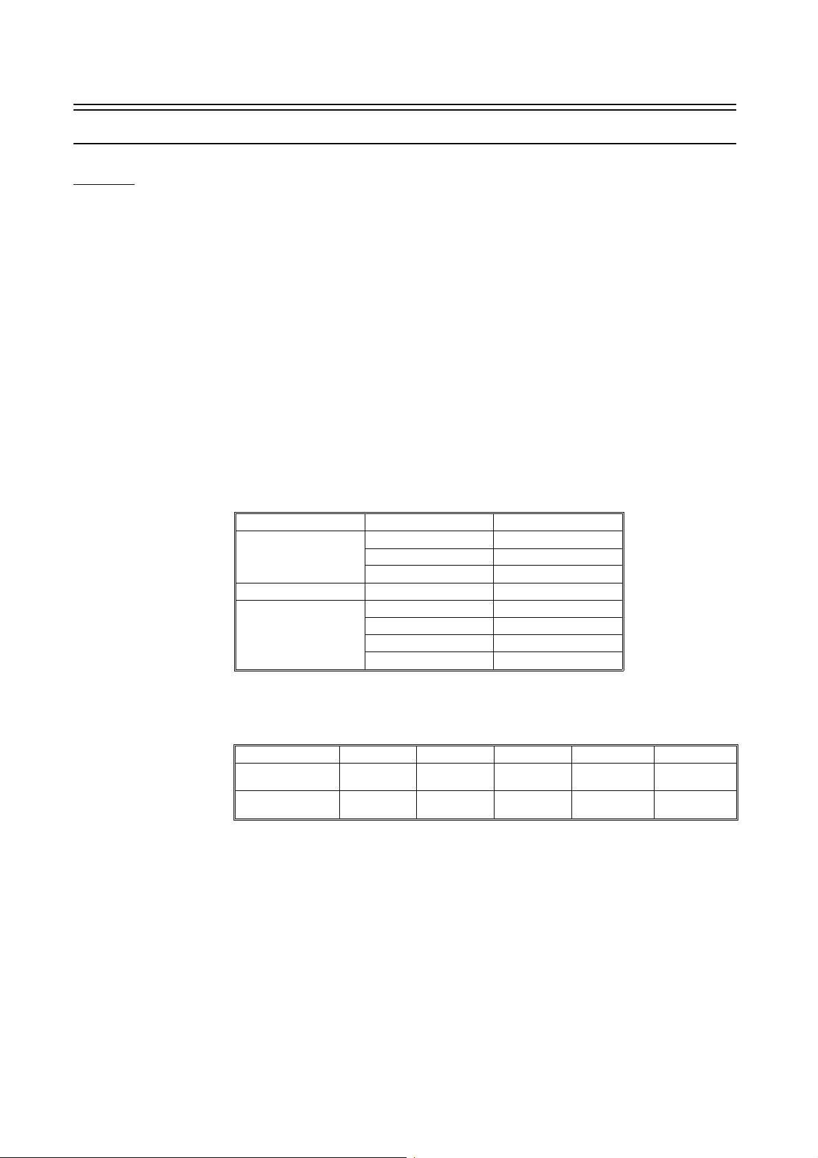
Reproduction Ratios: See the following table:
" x 11"
1/2
" x 11", A4, feed from 3rd tray)
1/2
" x 11", 8
1/2
" x 14", 8
1/2
" x 13")
1/2
LT/DLT version A4/A3 version
Enlargement
Full Size
Reduction
141% 141%
129% 122%
121% 115%
100% 100%
93% 93%
77% 82%
74% 71%
65% 65%
* Desired reproduction ratio(s) can be selected from 3 enlargements and 4 reductions.
Zoom: 64 ∼ 142% (1%/step)
Copy Tray Capacity: 200 sheets (80 g/m2 paper, in continuous copying mode)
Duplex Tray Capacity:
A3, B4, 11" x 17",
1/2
x 14"
8
1/2
" x 11"
1/2
" x 13",
A4, B5, 8
8
64 g/m2, 17 lb 80 g/m2, 20 lb 90 g/m2, 24 lb 105 g/m2, 28 lb 120 g/m2, 32 lb
50 40 35 30 26
80 80 70 61 53
Toner Replenishment: Cartridge exchange
Paper Feed: 1st tray: 500 sheets (80 g/m2, 20 lb paper, not exceeding load limit decal)
2nd tray:1,000 sheets (80 g/m2, 20 lb paper, not exceeding load limit decal)
3rd tray: 1,000 sheets (80 g/m2, 20 lb paper, not exceeding load limit decal)
Oil Tank Capacity: 3,000 cc
Power Source: 240 V, 60 Hz, 30 A
380/400/415 V, 50 Hz, 3 phase, 16 A/phase
Maximum Power 4.4 kW (Full system)
Consumption: 3.9 kW (Copier with RDH)
Weight: 499 kg, 1,100 lb (including RDH)
Environmental Conditions: Temperature: 10 ~ 30°C
Humidity: 15 ~ 90%
Standard Condition: 23°C, 65%
1-1
Specifications 6 November 1997
RDH
Original Size: Maximum: 11" x 17", A3
Minimum: B5
Original Weight: 64 ~ 120 g/m2, 17 ~ 32 lb
Original Set Capacity:
Original Weight
2
120 g/m
105 g/m
80 g/m
64 g/m
, 32 lb
2
, 28 lb
2
, 20 lb
2
, 17 lb
A3 or 11" x 17" B4 or 8
20 originals 20 originals 50 originals 50 originals
30 originals 40 originals 60 originals 60 originals
40 originals 60 originals 80 originals 80 originals
50 originals 100 originals 100 originals 100 original s
Original Size
1/2
" x 14" A4 or 8
1/2
" x 11" B5
Original Set: Face down
Original Feed Speed: 105 originals/minute (A4, 81/2" x 14" or smaller)
84 originals/minute (B4)
63 originals/minute (A3)
Power Source: 24 V, 3.6 A (from copier)
40 V, 1.5 A (from copier)
Maximum Power 130 W, 40 V, 1.5 A
Consumption:
Weight: 25 kg, 55.1 lb
ADF
Original Size: Maximum: 11" x 17", A3
Minimum: B5
Original Weight: 52 ~ 128 g/m2, 14 ~ 34 lb
41 ~ 157 g/m2, 11 ~ 43 lb or 90 lb index (when one original is set)
Original Set Capacity:
Original Weight
2
128 g/m
105 g/m
80 g/m
64 g/m
52 g/m
, 34 lb
2
, 28 lb
2
, 20 lb
2
, 17 lb
2
, 14 lb
A3 or 11" x 17" A4 or 8
18 originals 29 originals 29 originals
21 originals 36 originals 36 originals
27 originals 45 originals 45 originals
30 originals 50 originals 30 originals
30 originals 30 originals 30 originals
Original Set: Face down
Original Feed Speed: 84 originals/minute (A4, 8
63 originals/minute (A3)
21 originals/minute (2-up mod e)
Power Source: 24 V, 2.0 A (from copier)
Maximum Power 40 W
Consumption:
Weight: 12 kg, 26.5 lb
" x 14" or smaller)
1/2
Original Size
1/2
" x 11" B5
1-2
6 November 1997 Specificatio ns
1.1.2 LCT
Copy Paper Size: Legal (8
B4 (257 mm x 364 mm), A4 (210 mm x 297 mm),
B5 (182 mm x 210 mm)
Copy Paper Weight: Same as copier
Tray Capacity: Approximately 4,500 sheets (80 g/m2 paper, not exceeding upper limit decal)
Power Source: 100 V, 50/60 Hz (from copier)
Weight: 78 kg, 172 lb
" x 14"), Letter (8
1/2
" x 11"),
1/2
1.1.3 Finisher
Paper Size: Maximum: 11" x 17"/A3
Minimum: B5 sideways
Paper Weight: Standard copying: 52 ∼ 163 g/m2, 14 ∼ 43 lb or 90 lb index
Staple mode: 64 ∼ 80 g/m2, 17 ∼ 20 lb
Paper Capacity: Standard copying: 2,000 sheets: 8
1,000 sheets: Other sizes (20 lb/80 g/m2)
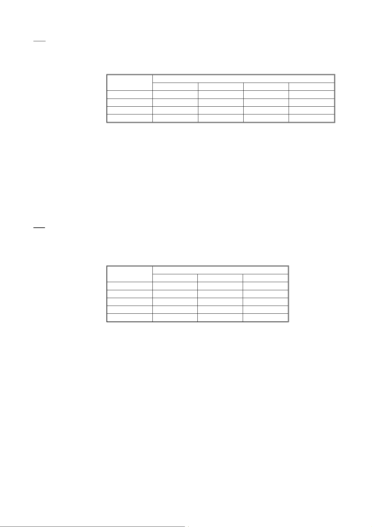
Staple mode: See the following table:
" x 11"/A4 or smaller size (20 lb/80 g/m2)
1/2
Number
of Originals
2 ∼ 10 sheets
11 ∼ 20 sheets
21 ∼ 30 sheets
31 ∼ 40 sheets
41 ∼ 50 sheets
Size
1/2
" x 11"/A4
8
or smaller size
100 sets* 100 sets 100 sets
100 sets 50 sets 50 sets
67 sets 34 sets 34 sets
50 sets 25 sets 25 sets
40 sets 20 sets —
*: Up to 100 stapled copy sets can be stacked because the stapled copy set makes an
uneven stack on the tray.
Stapling Capacity: 11" x 17"/A3 (20 lb/80 g/m2): from 2 to 30 sheets
Other sizes (20 lb/80 g/m2): from 2 to 50 sheets
Staple Replenishment: Cartridge exchange (5,000 pieces/cartridge)
Power Source: AC 100 V (from the copier)
Maximum Power 150 W
Consumption:
Weight 78 kg, 172 lb
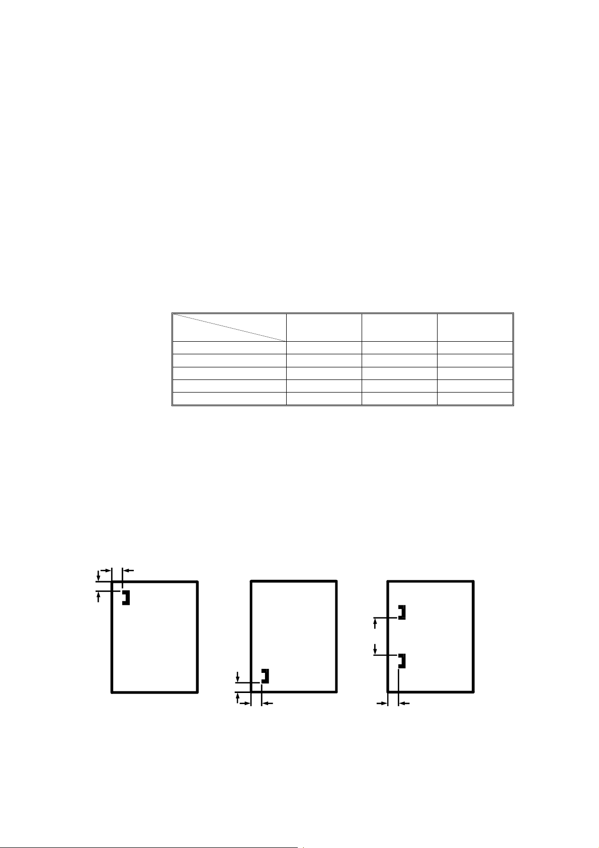
Stapling Position:
a
b
(1 staple) (2 staples)
1/2
x14"/B4 11" x 17"/A3
8
a = 0.2" ± 0.08" (5 ± 2 mm)
b = 0.2" ± 0.1" (5 ± 2.5 mm)
b
b
aa
a = 0.2" ± 0.08" (5 ± 2 mm)
b = 0.2" ± 0.1" (5 ± 2.5 mm)
a = 0.2" ± 0.08" (5 ± 2 mm)
b = 5.20" ± 0.08" (132 ± 2 mm)
(8
" x 11"/A4 or smaller size)
1/2
b = 10.5" ± 0.08" (265 ± 2 mm)
(8
" x 14"/B4 or larger size)
1/2
1-3

Noise 6 November 1997
1.2 Noise
During warm-up: 64 dB
During standby: 54 dB
Sound pressure level (The measurements are made according to ISO 7779.)
Full system
Operation position
bystander position
74 dB (A)
74 dB (A)
Sound power level (The measurements are made according to ISO 7779.)
Full system
Stand-by
Copying
67 dB (A)
85 dB (A)
1.3 Power Consumpti on
Copier only Full system*
Warm-up
Stand-by
Copying
Maximum
2.3 kW 2.4 kW
0.33 kW 0.41 kW
3.4 kW 3.6 kW
3.9 kW 4.4 kW
*Full system: Copier with large capacity tray and finisher.
1.4 Machine Dimensions
1.4.1 Full System
1-4
6 November 1997 Main Unit Layout Diagram
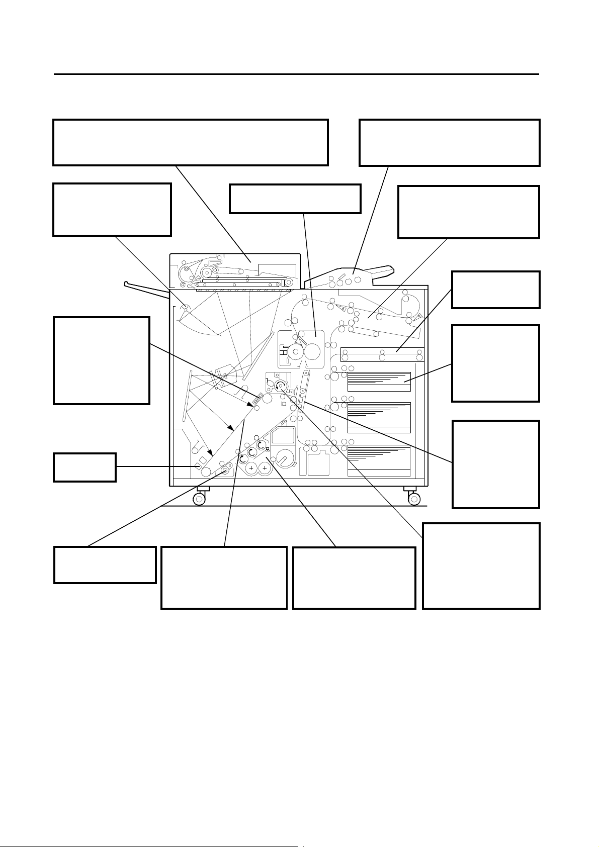
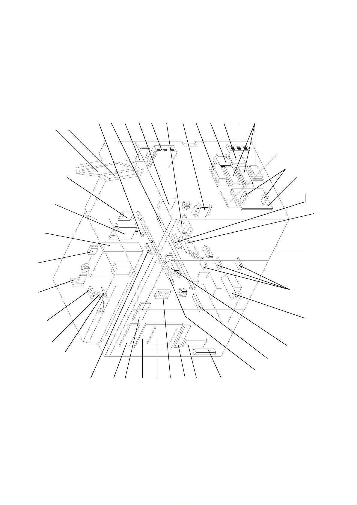
1.5 Main Unit Layout Diagram
RDH
The air knife separates the leading edges of the originals. The lowest
original is held against the trans port belts by the suction of the vacuum fa n
and fed by the belts. Even in one-to-one copying, this high-speed RDH can
meet 105 CPM. Automatic duplex copying is a lso available.
Exposure unit
A xenon lamp is used for flash
exposure. A stepper motor
moves mirrors and lens for the
desired magnification:
0.64 to 1.42
Charge corona unit
Scorotron system is
employed to gi ve a
uniform and constant
electric charge on the
OPC. (–) dc high voltage
is applied to a tungsten
wire, and the OPC is
charged negatively by
corona discharge.
Fusing unit
Heat and pressure roller system is
used with silicon oil.
ADF
The ADF accepts wider range of paper
thickness than the RDH. Friction separation
system is used and maximum 45 sheets (80
2
g/m
, 20 lb) of original can be set at a time.
Duplex unit
The air kni fe separates the leading
edge of the copies. The lowest copy
is held against the transport belts by
the suction of the vacuum fan and
fed by the bel ts .
Horizontal transport
unit
Transpor t s pa per from
the LCT.
Paper feed tray
The upper tray stacks
up to 500 sheets. The
middle and lower
trays stack up to
1,000 sheets. FRR
system is used as the
paper feed
mechanism.
Eraser unit
Erase system
employs LEDs.
OPC cleaning brush
Removes filming material
from the OPC surface and
refreshes OPC surface.
Photoconductor
An OPC belt is used as the
photoconductor. Its image
producing area is equally divided
into 5 A4/B5 segments, 4 B4
segments, or 3 A3 segments,
accordin g to the copy pap er size.
Development unit
Employs a magnetic brush
system using 3 magnetic rollers.
For toner density control, toner
density and ID sensors are
used. Toner is replenished from
a cartridge.
Transfer an d
separation unit
A high voltage
negative corona
transfers positively
charged toner to
paper. A high voltage
ac corona br ea k s t he
attraction between the
paper and OPC.
Cleaning unit
Magnetic brush system for
cleaning. Scavengin g roller
collects toner from the
magnetic brush. (–) dc bias
voltage is applied to the
cleaning roller and scavenging
roller. (+) dc is applied to the
PCC to increase cleaning
efficiency.
1-5
Electrical Component Layout 6 November 1997
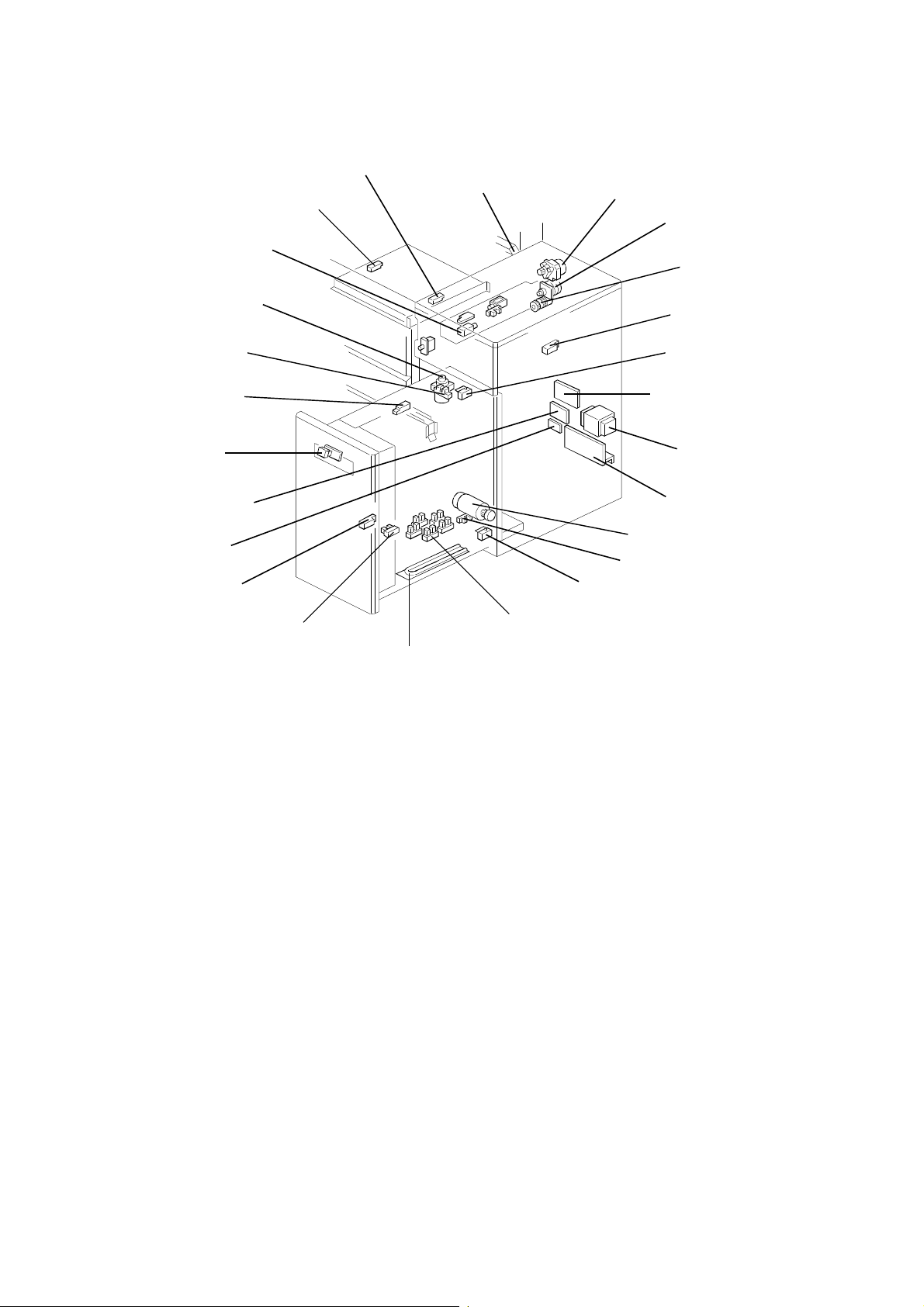
1.6 Electrical Component Layout
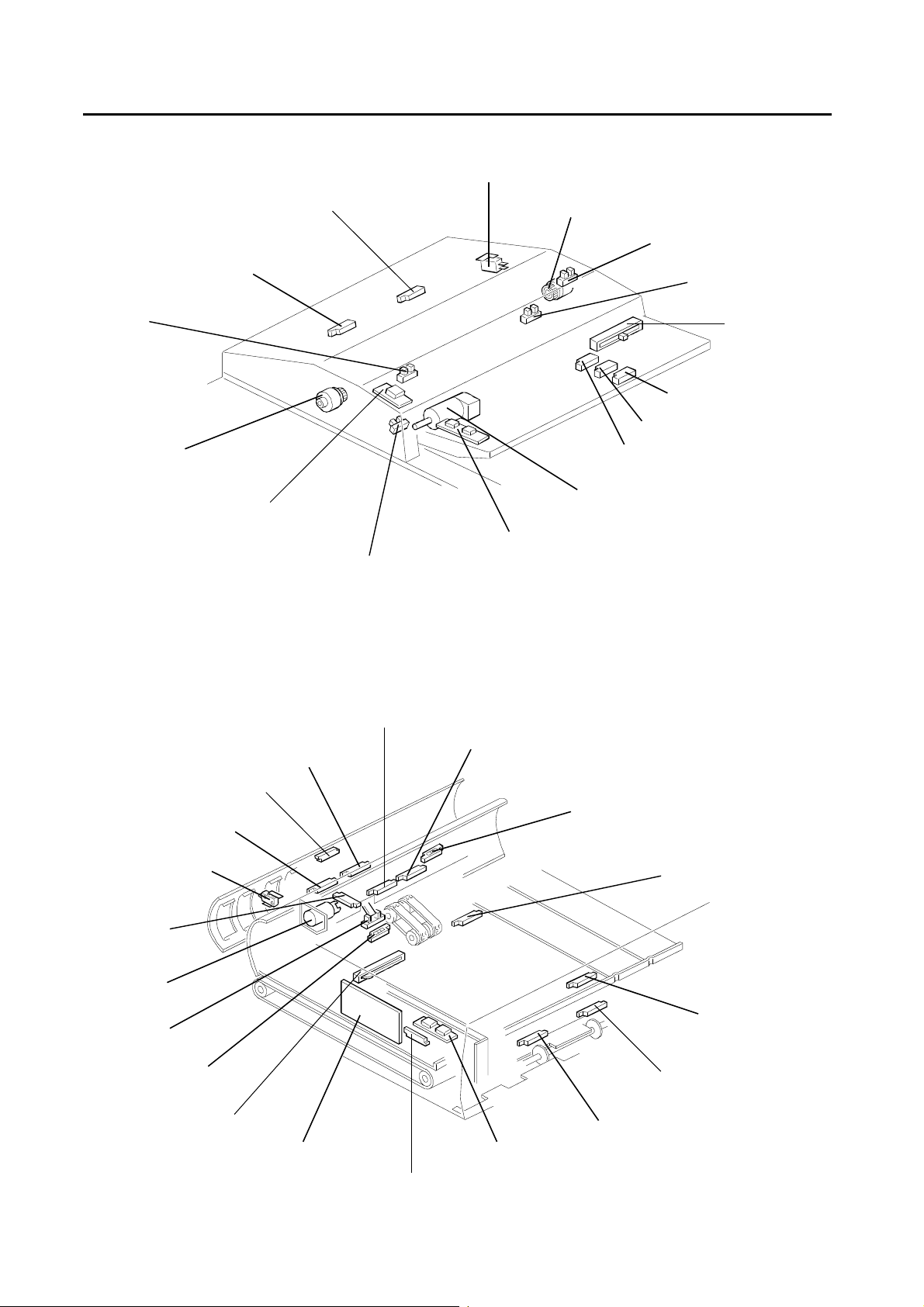
1.6.1 ADF
Feed Cover Safety Switch
Original Feed Sensor: Front
Original Sensor: Front
Separation Roller Clutch: Front
1 to 1 Start key
Original Feed Sensor: Rear
Pick-up Roller H.P. Sensor
Separation Roller Clutch: Rear
Entrance Cover Sensor
Original Sensor: Rear
ADF Size
Detection Sensor
Trailing Edge Sensor: B4
Trailing Edge Sensor: A4
Trailing Edge Sensor: B5
ADF Motor
Display Board
1.6.2 RDH Front View
2nd Reverse Sensor
1st Reverse Sen sor
Inverter C over Switch
Recycle Arm
Height Sensor
Recycle Arm
Solenoid
Recycle Arm
Sensor
Original Set Sensor
Original Size Sensor
ADF Exit Sensor: Front
ADF Exit Sensor: Rear
Entrance Sensor
Exit Sensor
1st Transport Sensor
2nd Transport Sensor
Registration Sensor: Rear
Registration Sensor: Front
Harness Relay Board
Display Board
Length Sensor
1-6
6 November 1997 Electrical Comp on en t La yo ut
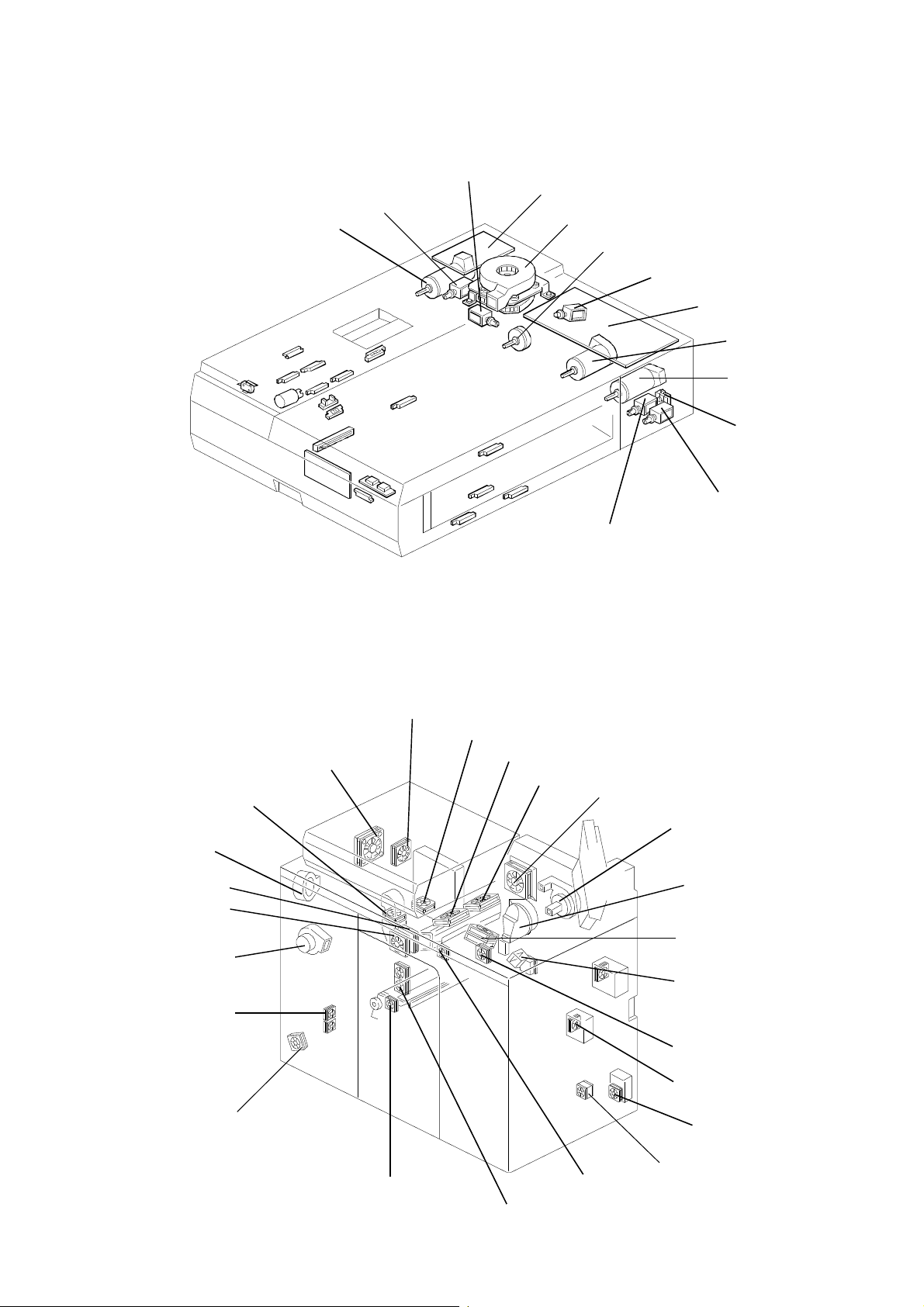
1.6.3 RDH Rear View
Reverse Junction Solenoid
ADF Exit Gate Solenoid
Revers e M o tor
Blower Control Board
Blower Motor
Original Feed Clutch
Shutter Solenoid
RDH Control Board
Original Feed
Motor
Transport Motor
Lift Switch
1.6.4 Fan Motor s
Rear Cooling fan
Flash Blower
2nd Fusing Cooling Fan
1st Fusing Cooling Fan
Front Cooling Fan
Flash Power Cooling Fan
Exposure Cooling Fan
Entrance Gate Solenoid
Registration Gate Solenoid
Flash Cooling Exhaust Fan
Front Curl Remover Fan
Rear Curl Remover Fan
Fusing Cooling Exhaust Fan
Duplex Blower
Vacuum Fan
Ozone Exhaust Fans
Cleaning Coil Cooling Fan
Inner Cover Cooling Fan
Eraser Blower
Cleaning Inside Cooling Fan
DC Power Cooling Fan
1-7
ID Sensor Blower
Paper Tray
DC Cooling Fan
Development
DC Cooling Fan
PCB Cooling Fan
Cleaning Cooling Fan
Electrical Component Layout Diagram 6 November 1997
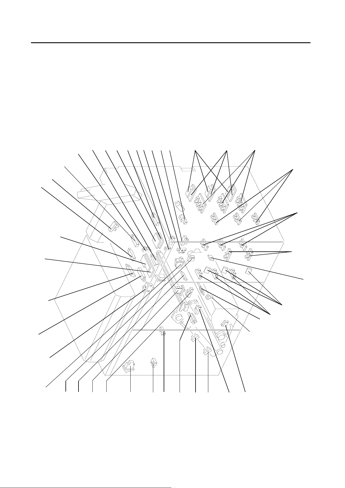
1.7 Electrical Component Layout Diagram
1.7.1 Copier
Switches and Se ns or s
Duplex Exit Sensor
Cleaning Coil Sensor
Eject Tray Sensor
Copy Tray Sensor
Duplex Entrance Junction Sensor
Upper Duplex Feed
Sensor Board
Lower Duplex Feed
sensor Board
Lower Duplex End Sensor
Eject Junction Sensor
Upper Duplex End Sensor
Separation Pawl Sensor
Jogger H.P. Sensor
Separation Motor Rotation Sensor
Back Fence H.P. Sensor
Right Upper Door Sensor
Paper Volume Sensor
DC Drive Board For Paper Tray
Paper Width Sensor Board
Paper Length Sensor
Paper Set Sensor
Lower Limit Sensor
Toner Near End Sensor
Fusing Exit Sensor
Tray Lowering Switch
ID Sensor
ADF Size Sensor
Upper Limit Sensor
Copy Tray Switch
Main Switch
Front Door Switch
Separation Sensor
Right Upper Door Switch
Cartridge Set Switch
Front Door Sensor
Flash Safety Switch
OPC Sensor
Magnification Sensor
Right Shield H.P. Sensor
Left Shield H.P. Sensor
Sector Sensor
Toner Density Sensor
Cartridge Shutter Switch
1-8
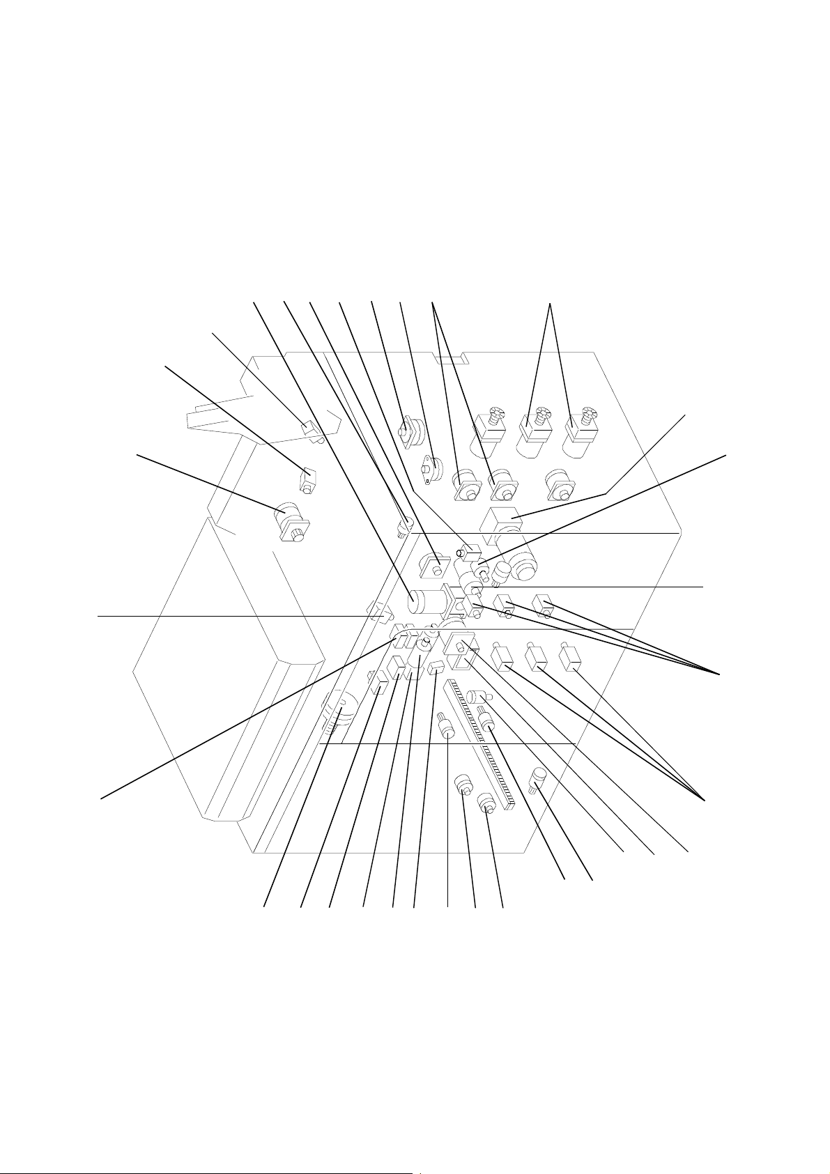
6 November 1997 Electrical Component Layout Diagram
Motor and Soleno ids
Back Fence Motor
Development Motor
Duplex Jab Separation Motor
Air Knife Solenoid
Duplex Vacuum Solenoid
Eject Junction Solenoid
Registration Motor
Jogger Motor
Paper Feed Motor
Tray Motor
Main Motor
Duplex Feed Motor
Relay 1
Duplex Entrance Junction Solenoid
Agitator Motor
Toner Supply Motor
Pick-up Solenoid
Reverse Roller Replace Solenoid
Oscillating motor
Tracking Motor
OPC Cleaning Motor
OPC Cleaning Brush drive Solenoid
Relay 3
Relay 2
Noise Filter
Mirror/lens motor
Circuit Breaker
Charge Wire Cleaner Motor
OPC Cleaning Brush Pressure
Left Shield Motor
Right Shield Motor
OPC Motor
1-9
Electrical Component Layout Diagram 6 November 1997
Others
Timer Board
Quenching Lamp
Thermistor
LCD Display
Operation Unit PCB
Cleaning Power Pack
Charge Power Pack
Flash Power Supply
SSR
ADF DC Power Supply
Paper Feed DC Power Supply
Power Transformer
Development Power Pack
Main/OPC Motor Drive Board
Duplex Blower Drive Board
Development DC Power Supply
Jogger Motor Drive Board
Paper Feed Motor Drive Board
Solenoid Drive Board
Dehumidification Heater
Paper Feed Control Board
QL Stabilizer
T & S Power Pack
Registration Sensor
Relay Board
Trigger Transformer
Xenon Lamp
Thermofuse
Potential Sensor
Thermofuse
Interface Board
Main Control Board
DC Motor Drive Board
Total Counter
Anticondensation Heater
Potential Control Board
Mirror/lens Motor Drive Board
Outside Ozone Exhaust Fan Battery
Fusing Lamp
Paper Feed Sensor
Toner Density Control Board
PCC Power Pack
1-10
6 November 1997 Electrical Component Layout Diagram
LCT
Entrance Sensor
Pick-up Solenoid
Horizontal Transport Exit Sensor
Paper Feed Sensor Board
Paper Feed Motor
Transport Motor
Paper Feed Clutch
Back Fence Motor
Back Fence Set Sensor
Upper Limit Sensor
Tray Lowering Switch
Transport Motor Drive Board
Relay Board
Paper End Sensor
Lower Limit Sensor
Back Fence H.P. Sensor
Upper Limit Overrun Switch
Paper Feed M oto r D r iv e B o ard
Transform er (A6595500)
LCT Board (A6595110)
Tray Motor
Paper Volume Sensor
Lower Limit Overrun Switch
LCT Size Sensors
Defumidification Heater
1-11

NEW FEATURES OF THE BIG BIRD (comparing with the F5) 6 November 1997
1.8 NEW FEATURES OF THE BIG BIRD (comparing with the F5)
Item Description
OVERALL
ADF The SADF mechanism has been modified into ADF whi ch enables maximum 45 (80
Copy Speed The copy speed has been increased from 101 CPM to 105 CPM.
Operatio n Unit To improve operation, a large LCD operatio n unit has been applied.
Paper Feed
Reverse roller pressure adjustment
mechanism
Reverse roller releas e mechanism This mechanism prevents paper, which is caught between the feed roller and the rev erse
The humidity sensor The humidity sensor has been removed. A swi tch to turn on/of f the paper tray heater has
Fusing
Oil collecting tube To prevent the oil collecting tube from cloging, the shape of the oil collection part has
Serviceability of f using unit The metering blade removal procedure has become easier.
2
g/m
, 20 lb) continuous original feed.
The reverse roller pressure adjustment mechanism has been added to counter paper
multi-feeds or misfeeds due to various friction of the paper surface.
roller, from tearing when the paper tray is pulled out. W hen a paper feed operation is
finishe d, the reverse roller release solenoid (2-way solenoid) is energized to release the
reverse roller from the feed roller.
been added instead.
been modified.
Duplex
Duplex multi-feed detection mechanism Duplex multi-feed detection mechanism has been added. Number of a copy set i s
Reverse roller pressure adjustment
mechanism
Modification of the duplex vacuum unit To increa se the margin for the duplex multi-feeds, the shape of the duplex vacuum unit
LCT
Paper Tray Capacity The paper tray capacity has been increased from 3,000 sheets to 4,500 sh eets.
Unifying the rear side fence for LT version
and A4 version
Doors for Jam Removal The upper cover has been fixed. The upper front door can be opened instead.
Electr ical Component Layout The positions of the LCT control board and the transformer have been changed to the
Manual Tray Unlock Mechanism To enable pulling out the paper tray when the power is off, even if the paper table is up,
Reverse Roller release Mec hanism Same as the copier paper feed.
Reverse roller pressure adjustment
mechanism
Finisher
Stapler The type of the stapler has been changed. (Refer to Sectional Description)
detected by this mechanism, and duplex multi-feed is d etected if the number is less than
the number of the original.
Same as the paper feed unit
has been modified. Additi onally, to counter the misfeeds of A3 copies in the duplex unit,
the speed of t he duplex vacuum fan motor has been changed.
The two types of the rear side fence have been unified into 1 type which can be used for
both LT version and A4 version.
rear side of the LCT to inc rease tray paper capacity.
the manual tray unlock mechanism has been added. (Refer to Sectional Descriptions)
Same as the co pier paper feed.
1-12

6 November 1997 NEW FEATURES OF THE BIG BIRD (comparing with the F5)
1.8.1 SPEC UP POINTS (Comparing with F5)
Item Big Bird F5
Copy Speed 105 cpm (A4/LT) 101 cpm (A4/LT)
First Copy T ime 6.5 seconds 6.7 seconds
ADF Yes (Max. 50 sheets) No (SADF only)
2-up Mode Yes No
LCT Paper Capacity 4,500 sheets 3,000 sheets
Preset Mode Yes No
Sample Copy Yes No
Margin Erase Yes No
Program Mode 25 job settings 10 job settings
Manual Image S etting 13 steps 7 steps
Tab Copy Yes No
1-13

SECTION 2
DETAILED SECTIONAL DESCRIPTIONS
6 November 1997 Paper Feed
2. DETAILED SECTIONAL DESCRIPTIONS
2.1 Paper Feed
2.1.1 Reverse Roll er Release Mechanism
To prevent the paper getting caught between the feed
roller [A] and the reverse roller [B] and tearing when the
paper tray is pulled out, a reverse roller release
mechanism is used.
At 20 ms after the Print key is pressed, the reverse roller
release solenoid [C] is energized for 540 ms to pull the
link [D]. The reverse roller is pushed up to the feed roller
due to the spring tension. Th e soleno id keeps its
position after it is de-energized.
At 8 seconds after the last paper of the copy job is fed
(or 8 seconds after a paper jam is detected), the
solenoid is energized to move the link in the direction of
the arrow, and the reverse roller is released from the
feed roller.
[A]
[B]
[D]
[C]
2.1.2 Separation Pressure Adjustment Mechanism
To counter paper misfeed or mult i-fe ed caused by
variations in the friction of paper surfaces, a separation
pressure adjustment mechanism has been added.
By changing the positions of the gears [E] which transfer
the motor drive to the reverse roller [F], the pressure
between the feed roller and the pressure roller will be
changed.
To counter paper multi-feed, the gear position should be
shifted to the rear side to decrease the pressure.
2.1.3 Anti-humidity Heater Switch
To prevent the paper from absorbing moisture,
anti-humidity heaters are installed in the 2nd tray and
the 3rd tray.
The heaters can be turned on and off with the switch on
the left side of the machine independent from the main
switch.
[E]
[F]
2-1
Duplex Unit 6 November 1997
2.2 Duplex Unit
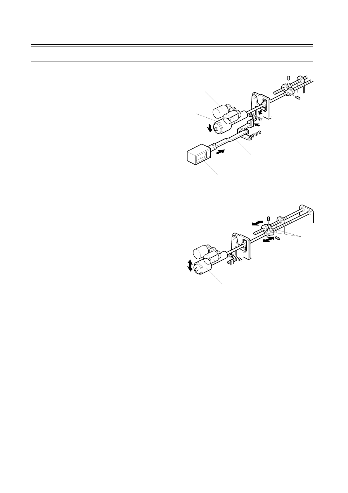
2.2.1 Duplex Multi-feed Detection Me chanism
To detect paper multi-feeds in single-sided to
double-sided copies, a detection mechanism has been
installed in the duplex unit.
When the last page of a set of copies has been
delivered to the duplex unit, the duplex separation motor
[A] is energized, and the separation pawl [B] is set on
the top of the paper stack. The motor stops when the
separation motor rotation sensor [C] is actuated.
When the last paper of the set is fed out, the sepa rat i on
pawl rotates in the direction of the arrow, and the
separation pawl sensor [D] is activated.
The CPU counts the number of the copies, and if the
number is less than the number of the originals, a duplex
multi-feed is detected and copying stops.
To recover a duplex multi-feed, the operator should
remove the set of copies in the shift tray, and the original
should be reset on the RDH in the original order.
[D]
[B]
[A][C]
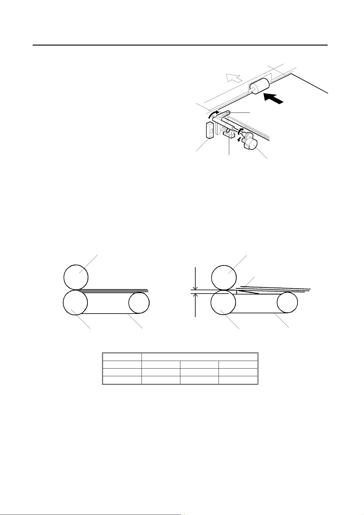
2.2.2 Duplex Vacuum Un it (The Difference Betw een the F5 model and the Big Bird)
To reduce the possibility of duplex multi-feeds, the shape of the duplex vacuum unit guide [E] has been changed.
Also, the angle of the paper which goes in the separation section has been changed.
Additionally, to reduce misfeeds when A3/DLT size paper is used, the vacuum fan speed has been changed as shown
below.
Reverse Roller
Feed Roller
Paper Stack
F5
Big Bird
3.5 mm
Transport Belt
Vacuum Fan Speed (rpm)
1 to 20 21 to 35 36 or more
4,500 6,000 7,000
6,000
←
Feed Roller
7,000
Reverse Roller
[E]
Transpor t Be lt
2-2
6 November 1997 Operation Unit
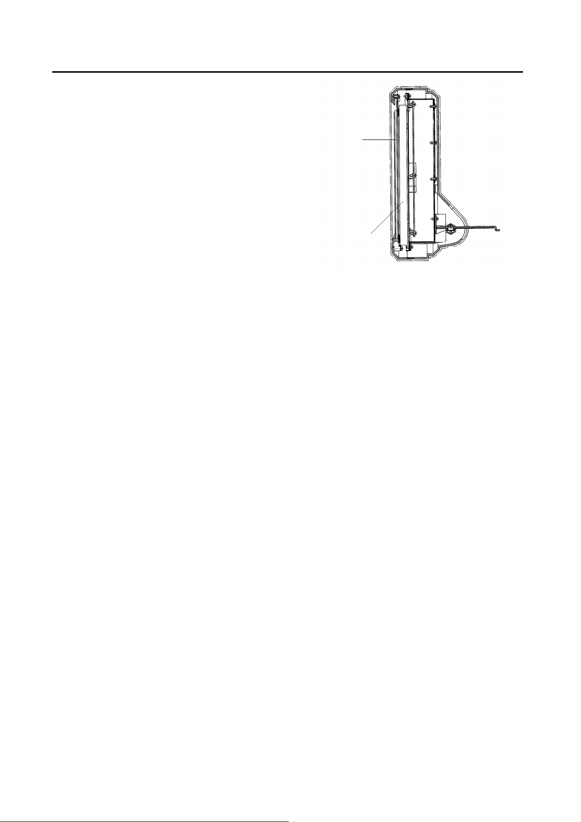
2.3 Operation Unit
The 680 x 480 dot LCD [A] is used for the operation unit.
The display is covered by the touch panel [B] which is an
analog resistor type.
The operation unit control board detects the position that
an operator touches by scanning the matrix of the touch
panel.
A LED indicator is installed on the top of the operation
unit. The indicator shows the conditions of the machine
as follows:
Green: The machine is in the ready condition.
Red (lights): The machine is operating.
Red (blinks): The machine is has a problem.
[B]
[A]
2-3
RDH/ADF 6 November 1997
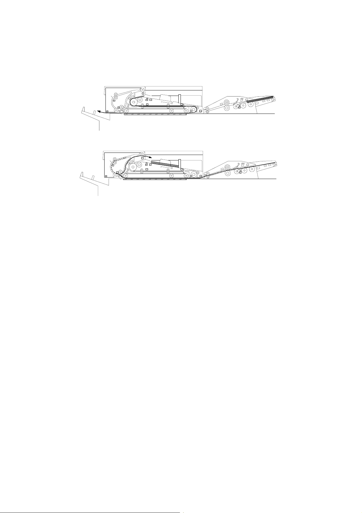
2.4 RDH/ADF
A newly added ADF, which transports originals straight
through, accepts thinner originals which cannot be used
in the RDH. As only 1 set of copies can be made using
the ADF at a time, this should be used to make a copy of
a fragile original. Multiple copies of this can then be
make with the RDH.
2.4.1 Overall
When the Start key (or the 1-to-1 Copy Start key) is
pressed after the original is set in the ADF, the bottom
page is separated from the original stack and
transported to the exposure glass.
In the 1-to-1 mode, after the original is exposed, it is
transported to the original exit tray.
In the duplex mode, the original is inverted in the RDH
after the front side is exposed and transported to the
exposure glass again. Then the reverse side is exposed
and inverted. Then original is transported to the original
tray.
The original feed interval of the ADF is longer than the
RDH, so the A4 1-to-1 copy speed of the ADF is 84 cpm.
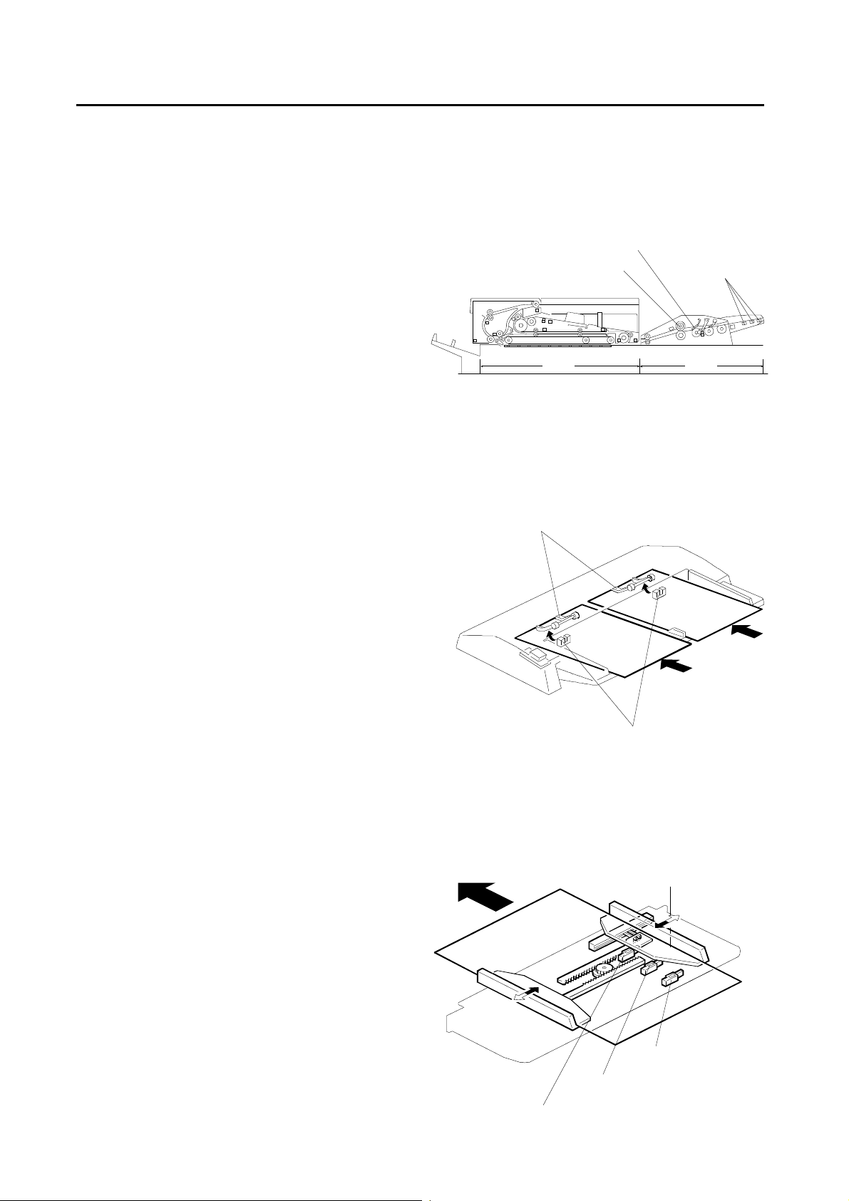
2.4.2 ADF Original Detection
When an original stack is set on the original table, the
original sensor feeler [A] is pushed up by the original
and the original sensor [B] is activated.
To detect two sets of originals separately in the ADF
2-up mode, two original feelers are used for original
detection. If 2-up mode is not selected, the original is
detected when one of the sensors is activated.
There are two indicators on the ADF original feed
section: Original Set and Auto Feed. The Original Set
indicator turns off when an original is inserted. The Auto
Feed indicator lights for 5 seconds after the last copy
using the ADF is finished. If an original is set while this
indicator is lit, the machine automatically starts feeding
the original.
If the "1-to-1 Copy Start key" is pressed while an original
is set, one if copies is made from the original, ignoring
the operation panel setting.
If original stacks are set both in the ADF and the RDH,
the machine starts copying the originals in the RDH
when the Start key is pressed.
2.4.3 ADF Size Detection
When one of the side guides is slid, the other guide also
moves due to the rack and pinion. The lever of the ADF
size detector (a variable resistor) [C] moves with the rear
guide. The original width is detected by checking the
potential of the sensor terminal. As the difference of the
width between LG and B4 is too small to detect,
reflective photo-sensor (trailing edge sensor - B4) is
used to distinguish between B4 and LG.
The three reflective photo-sensors are used to detect the
trailing edge of the last original. The paper feeding must
be stopped just after the last original is started (paper is
fed before the original is fed, because the paper path is
long).
Relay Roller
RDH
[A]
Friction Blade
Trailing Edge
Sensors
ADF
[B]
[C]
Trailing Edge Sensor: B4
Trailing Edge Sensor: A4/LT
2-4
Trailing Edge Sensor: B5
6 November 1997 RDH/ADF
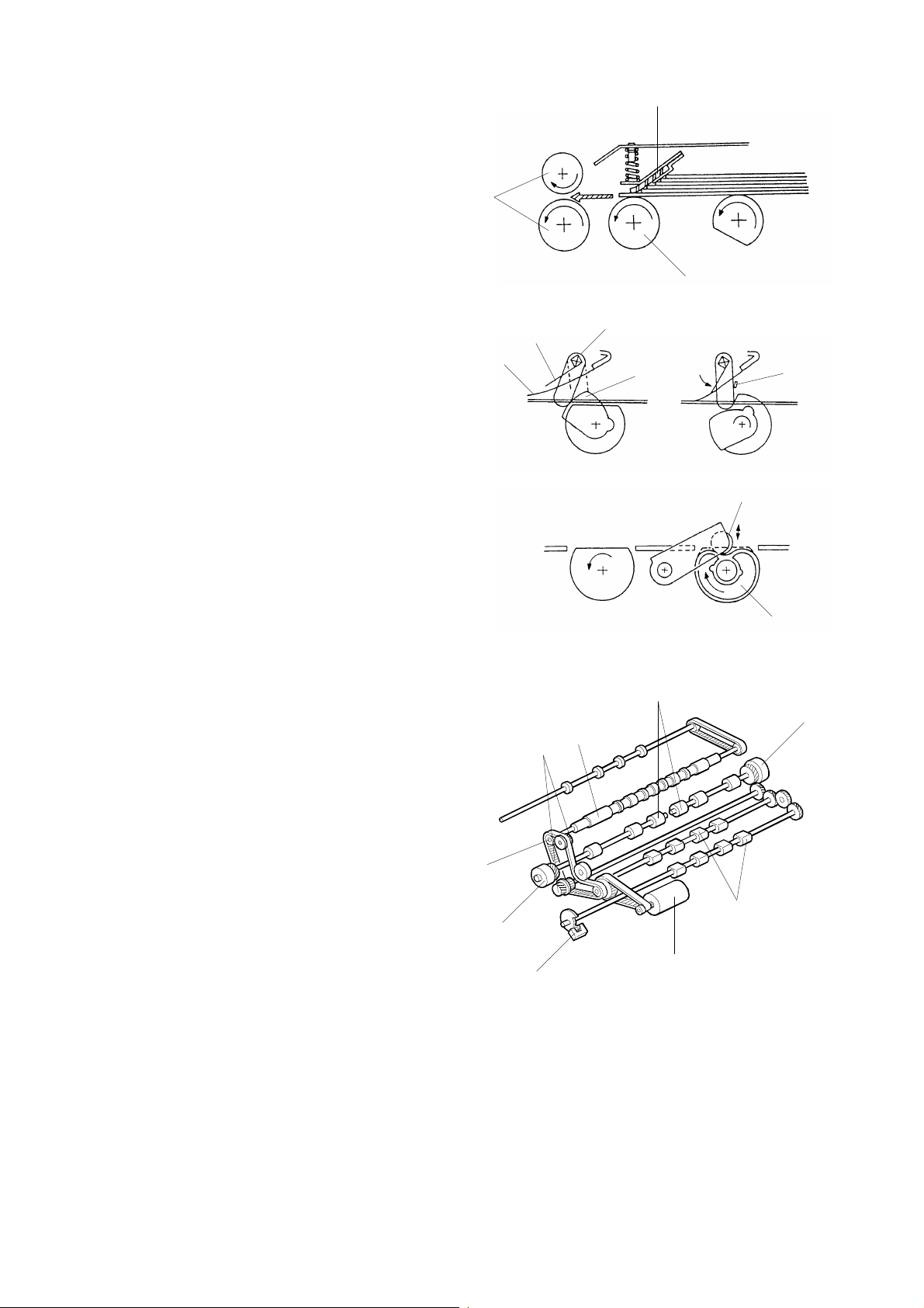
2.4.4 ADF Separatio n M echanism
After the Start key is pressed, the bottom original is
separated by the separation rollers [A] and the friction
blade [B] and it is transported to the relay rollers [C].
The separation rollers have a one- way clutch inside .
After the drive motor stops, the rollers continue to turn in
the feed direction.
The friction blade is pressed against the separation
rollers by two adjustment screws at the front and rear of
the blade holder.
2.4.5 Pick-up Roller
The entrance guide mylar [D] holds the originals against
the pick-up rollers to facilitate paper feed.
The pressure release cam lobe [E] pushes the lever [F]
upward to release the pressure mylar [G]. This makes it
easier to set the originals.
During paper feed, the cam rotates and the pressure
mylar pushes down the entrance guide mylar because of
the force of the return spring. The pressure mylar lever
stops at the stopper [H] to prevent too much pressure
being applied.
A heart shape cam [I] is installed on the pick-up roller
shaft. When the cam follower [J] drops into the
depressed portion of the heart-shaped cam, the pick-up
roller stops. At this time, the flat surface of the pick-up
rollers is level with the original table.
[C]
[D]
[G]
[F]
[E]
[B]
[A]
[H]
[J]
[I]
2.4.6 ADF Drive Mechanism
The two-directional original feed motor [K] drives the
pick-up rollers [L], the separation rollers [M], and the
lower relay roller [N]. Two one-way gears [O] and a
one-way pulley [P] control the roller rotation.
Upon receiving the paper-feed signal from the copier,
the original feed roller rotates clockwise, and the pick-up
rollers and the upper relay roller rotates in the paper
feed direction. The pick-up roller has a home position
sensor [Q]. When the sensor detects that the roller has
completed a full turn, the original feed motor starts
reversing.
When the motor reverses, the one-way pulley and the
gear driving the pick-up and separation rollers become
idle and the rollers stop. The relay rollers continue to
turn in the paper feed direct ion beca use of the one-wa y
clutched.
Two separation shafts and two electromagnetic clutches
[R] are used to control the front and rear separation
rollers separately. In normal mode, the two clutches are
energized at the same time to transmit the rotation of the
original feed motor. In ADF 2-up mode, when one of the
original stacks is finished, the clutch for the finished
original is de-energized to prevent the separation rollers
from wearing.
[P]
[R]
[Q]
[O]
[N]
[M]
[R]
[L]
[K]
2-5
RDH/ADF 6 November 1997
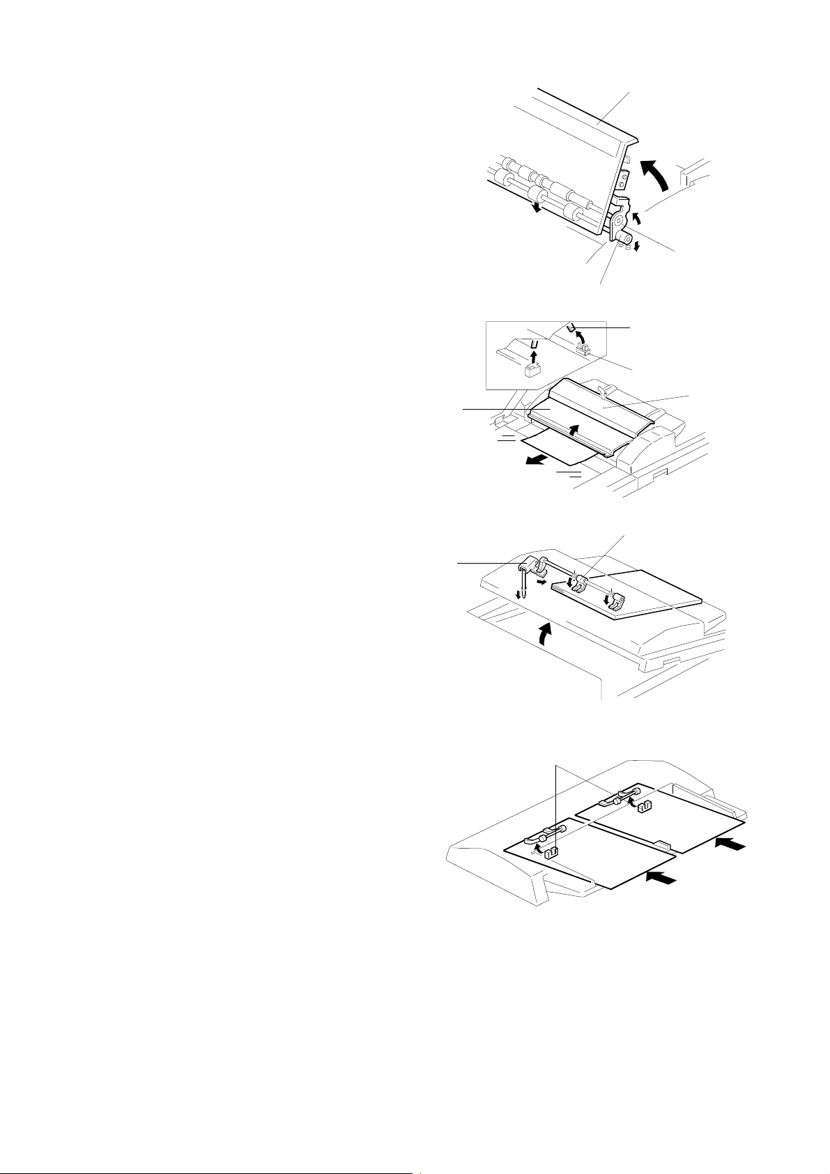
2.4.7 Relay Roller Pressure Release Mechanism
When the ADF right cover [A] is opened, the bushing [B]
of the pull-out roller is pressed down by the raised
portion of the friction blade frame [C]. This releases the
pull-out roller pressure to make misfed originals removal
easier. The feeler [D] moves away from the entrance
cover sensor [E], and the machine detects that the cover
is open.
The ADF left cover [F] also can be opened for easy jam
removal.
[A]
[C]
[B]
[D]
[E]
[A]
[F]
2.4.8 ADF Original Hold Mechanism
To prevent the originals in the ADF from dropping when
the duplex door is opened, an original hold mechanism
is installed.
While the duplex door is closed, the lever [G] is pushed
up by the shaft, and the original holding arms [H] are
released from the originals.
When the duplex door is opened, the shaft moves down
and the originals are held by the arms.
2.4.9 ADF 2-up Mode
In ADF 2-up mode, two originals (lengthwise) are fed
together to the exposure glass, and the originals are
copied together on one sheet.
To detect the front and rear originals separately, two
photosensors [I] and two actuators are used, and the
front and rear separation rollers are controlled
separately using two electromagnetic clutches.
When both front and rear original set sensors are
actuated, the front and rear separation roller clutches
are energized at the same time. When one of the
originals is finished, copying stops. If the Print key is
pressed in this condition, copying starts again by driving
only the separation rollers for the remaining originals.
In normal copying, the original runs 7 mm after the
trailing edge of the original passes the right scale, then it
is reversed 12 mm make sure it steps against the right
scale.
In ADF 2-up mode, the original runs 15 mm and
reversed 30 mm This extra reverse feed ensures that
the original steps against the right scale. It is needed
because the original is fed lengthwise an has less
contact with the rollers, so slippage is more.
"Center Erase" is automatically selected in 2-up mode.
[H]
[G]
[I]
2-6
6 November 1997 RDH/ADF
2.4.10 Preset Mode
Using Preset mode, the second copy job, which automatically starts after the 1st job is finished, can be set while the 1st
copy job is in progress.
To enter the Preset mode, the operator should press the "Preset" key on the display while the machine is operating in the
RDH mode.
In Preset mode, the RDH and the ADF operate in the following steps:
After the RDH job is finished, the originals in the RDH are delivered to the original exit tray one by one.
The originals in the ADF are transported into the RDH one by one.
The 2nd job is operated in RDH mode.
After the job is finished, the originals stay in the RDH.
There are several limitations and notes concerning the Preset mode.
•
The original size for the 2nd job must be the same as the 1st job.
•
Cover Sheet mode, Slip Sheet mode, and size magnification cannot be used in the 2nd job.
•
The Interrupt key is disabled while the Preset mode is used.
•
The Energy Saver key is disabled while the Preset mode is used.
•
Preset mode cannot be used with Stack mode.
•
Preset mode cannot be used with 2-up mode.
•
Preset mode cannot be used with Thin Paper mode.
The machine checks if the 2nd job is possible, after the 1st job is finished.
The 2nd job is automatically canceled in the following conditions.
•
If a User Program is operated or the RDH original is removed while the machine is standing by.
•
If the front door is opened while setting up the 2nd job at the operation panel.
•
If a paper jam occurs during the 1st job.
•
If an original jam occurs while the original in the ADF is transported to the RDH.
2-7

RDH/ADF 6 November 1997
2.4.11 ADF Electrical C omponent Defects
The table below shows the expected symptoms when a photosensor is defective.
Sensor Sensor Status Expected Symptom
Trailing Edge
Sensor (B4)
Trailing Edge
Sensor (A4/LT)
Trailing Edge
Sensor (B5)
Pick-up Roller
H.P. Sensor
Original Set
Sensors
Original Feed
Sensors
ON
OFF
ON
OFF
ON
OFF
ON
(Interrupted)
OFF
(Not interrupted)
ON
OFF The machine works normally in normal mode. If 2- up mode is used, the original is not fed.
ON An original ja m is detecte d after the Start key is pressed.
OFF An original jam is dete cted after the Start key is pressed.
When an A4/LT or smaller original is used, the machine works normally. I f a l arger original is used,
an original jam is detected.
When an A4/LT or smaller original is used, the machine works normally. I f a l arger original is used
and the number of sheets is more than 2,copying stops after 2 sheets are copied. Even if the
original is larger than A4, the machine works normally if the number of the originals is 2 or less.
When an A4/LT s ize original is used, the machine work s normally. If the original size is not A4, an
original ja m is detected.
When an A4/LT or smaller original is used, the machine works normally. I f a l arger original is used
and the number of sheets is more than 2, copying stops afte r 2 sheets are copied. Even if the
original is larger than A 4/LT, the machine works normally if the number of sheets is 2 or less.
When an A4/LT or la rger original is used, the machine works normally. If B5 size paper is used,
paper jam is detected.
When A4/LT or larger size original is used, the machine works normally. If B5 size paper is used, a
paper jam is detected. If B5 size paper is used and the number of sheets is more tha n 2, copying
stops afte r 2 sheets are copied. Even if the original is B5, the machine works normally if the
number of sheets is 2 or less.
The pick-up roller turns for 1 second, then the "READY" lamp turns off.
The pick-up roller turns for 1 second, then an original jam is detected.
The machine works normally in normal mode. If 2-up mode is used, an original jam is detec ted
after the last original is fed.
2-8

6 November 1997 LCT
2.5 LCT
2.5.1 Manual Tray Un l ock Mechanism
To enable the paper tray to be pulled out when the
power is off, even if the paper table is up, a manual tray
unlock mechanism has been added.
Normally, when the paper table is up, the lever [A] locks
the paper tray and it cannot be pulled out.
If the release lever [B] is pushed up, the arm [C] pushes
down the lock lever, and the paper tray is unlocked.
[C]
[A]
[B]
2-9
Finisher 6 November 1997
2.6 Finisher
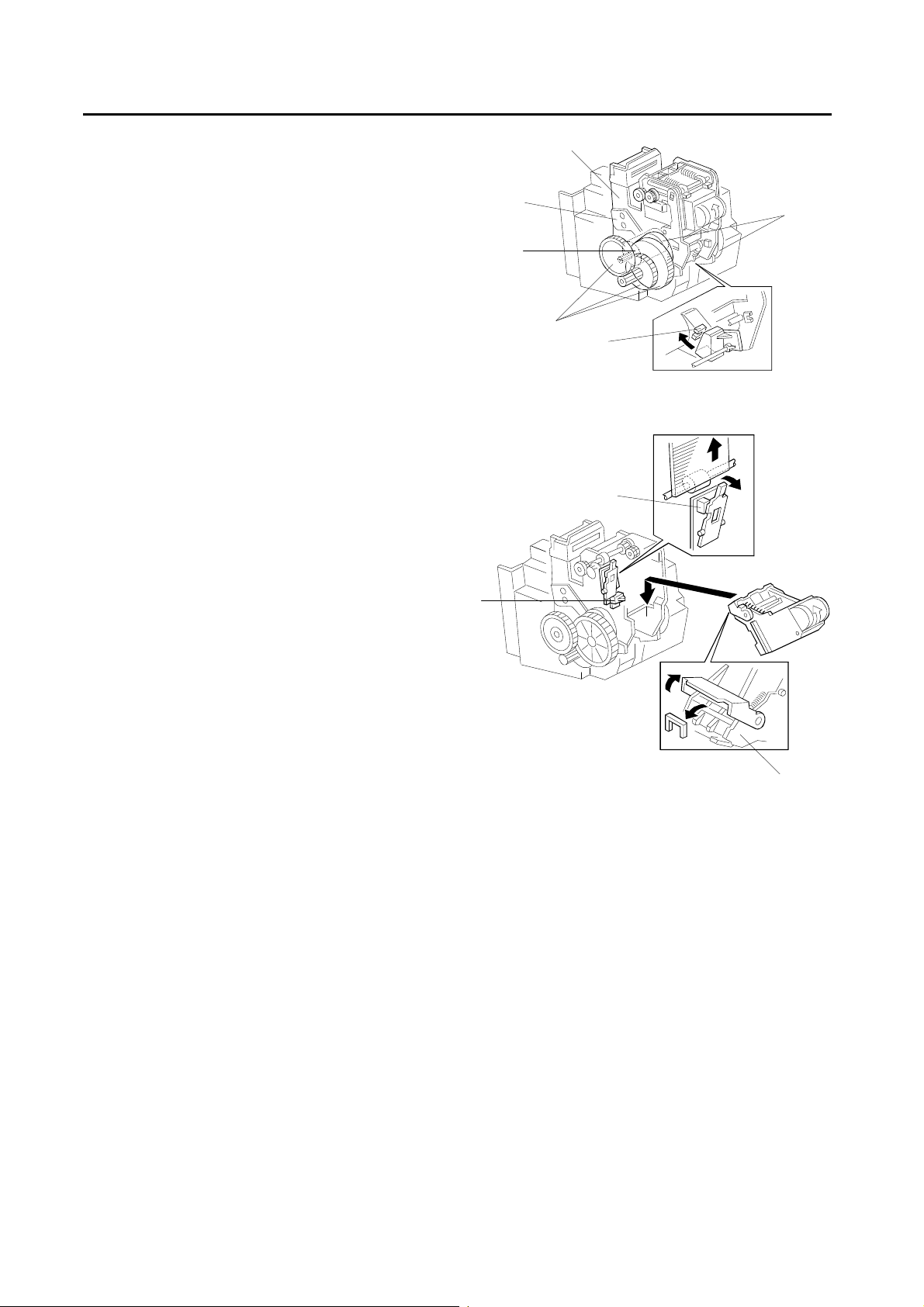
2.6.1 Stapler
The staple hammer [A] is driven by the stapler motor [B]
via gears [C], two eccentric cams [D], and two links [E].
When the aligned copies are brought to the stapling
position by the positioning roller, alignment brush roller
and jogger fences, the stapler motor starts. When the
cams complete one rotation, the staple hammer home
position sensor [F] turns on, detecting the end of the
stapling operation. The stapler motor then stops.
There are two sensors in the stapler unit. One is the
staple end switch [G] for detecting staple end conditions
(it detects when there is only one sheet of staples left in
the cartridge). The other is the cartridge set switch [H]
for detecting whether a staple cartridge is installed.
When a staple end or no staple cartridge condition is
detected, a message is displayed advising the operator
to install a staple cartridge. If this condition is detected
during a copy job, the indication will appear, but will not
stop the copy job.
The staple cartridge has a clinch area [I], in which the
jammed staples are left. Operators can remove the
jammed staples from the cartridge.
[E]
[B]
[A]
[D]
[C]
[F]
[G]
[H]
[I]
2-10

SECTION 3
INSTALLATION
6 November 1997 Installation Requirements
3. INSTALLATION
3.1 Installation Requirements
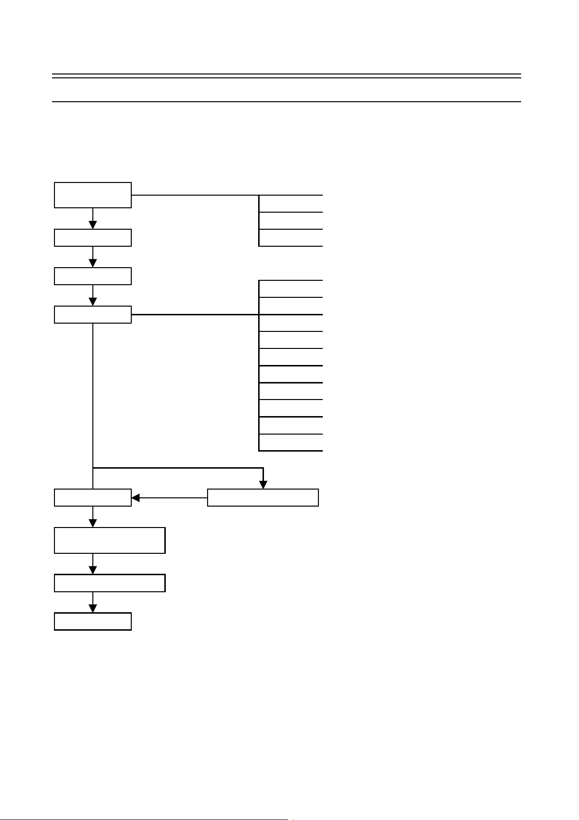
3.1.1 Delivery And Ins tallation Work Flow
Installation
condition check
Delivery
Clamp removal
Main body setup
•
Installation environment, floor strength
•
Space around the machine, delivery route
•
Power supply
•
The user's acceptance of the limited items for
using the machine (See User Guidance
Items section for the limited items.)
•
Supply developer
•
Supply cleaning carrier
•
Set the OPC belt
•
Supply silicone oil
•
Install the cleaner carrier and development vessels
•
Install the operation unit
•
Install the power plug and cord
•
Leveling
•
Install the original stacker
•
Install the toner cartridge
•
Add copy paper
Machine power on
Operation check as far as the
machine stand-by condition
Machine operation check
User guidance
Installation of peripherals
3-1

Installation Requirements 6 November 1997
3.1.2 Environment
Select the conditions which fully satisfy the following items at installation.
1.
Avoid a place exposed to direct sunlight or other strong light (should be below 1500 lux).
2.
Avoid locations with high temperatures or high humidity, or low temperatures and low humidity. (Standard range of
temperature and humidity: 10°C to 30°C, 15% to 90%)
3.
Avoid places with hot air or strong heat sources.
4.
Avoid locations subject to abrupt temperature changes.
5.
Avoid small or dusty rooms.
6.
Avoid poorly ventilated locations. (Air turnover should be 3 times or more per hour per person.)
7.
Install the machine flat on the floor. It must be level within 5 mm front to rear and 5 mm left to right. This is mainly
to prevent tilt from affecting the tracking operation of the OPC belt.
8.
Align the position of the LCT and finisher with the copier. First, adjust the height of the peripherals on the basis of
the exterior cover position. Finally, align the paper transport guide plate height between each unit. This is to
prevent paper misfeeds where each unit connects.
9.
The unit must be installed on a floor which can support its total weight: copier including ADF 499 kg, finisher 77
kg, and LCT 78 kg.
10.
Provide enough space, 100 cm in front, 60 cm in rear, and 30 cm on both sides for operation and service. No
fluorescent lights should be installed above the operation unit. (This is to make it easier to see the operation
display.)
3.1.3 Power connection (For the European version machine only)
1.
Plug
The plug must be approved under the TÜV safety standard and for a three-phase power supply.
2.
Power supply cord
1) The cord must be approved under the TÜV safety standard and have five wires inside. The cross-sectional
area of each wire must be 2.5 mm2, and the outside diameter of the cord must be 14 to 18 mm. (The capacity
must be over 600 volts and 16 A for each phase.) The length must be 5 m or less even if an extension cord is
used.
2) The socket outlet of the power source must be installed near the copier and must be easily accessible. (If the
power supply cord is permanently connected, a readily accessible disconnect device must be incorporated in
the fixed wiring.)
3-2
 Loading...