

Page 1
RICOH FT9101
FIELD SERVICE MANUAL
LARGE CAPACITY TRAY RT32
FINISHER SR500
PRINTER CONNECTOR UNIT PCU10
KEY COUNTER/PRINTER
CONNECTOR BRACKET KP10
COMPANY, LTD.
Page 2

Read This First
A few simple symbols and notations are used to help you read faster and find the information you
need. Before you use this guide, glance over this list of special notations and be sure you
understand what they mean.
NOTE
Information under this heading describes helpful hints, restrictions, and how to avoid difficulties.
CAUTION
Failure to pay attention to CAUTION notices can
result in damage to the equipment.
WARNING
Warnings are for your safety. Failure to pay
attention to WARNING information can be
dangerous to you and others.
Page 3

IMPORTANT SAFETY NOTICES
PREVENTION OF PHYSICAL INJURY
1. Before disassembling or assembling parts of the copier and peripherals,
make sure that the copier power cord is unplugged.
2. The wall outlet should be near the copier and easily accessible.
3. Note that some components of the copier are supplied with electrical
voltage even if the main switch is turned off.
4. If any adjustment or operation check has to be made with exterior covers
off or open while the main switch is turned on, keep hands away from
electrified or mechanically driven components.
5. The inside and the metal parts of the fusing unit become extremely hot
while the copier is operating. Be careful to avoid touching those
components with your bare hands.
HEALTH SAFETY CONDITIONS
1. Never operate the copier without the ozone filter installed.
2. Always replace the ozone filter with the specified one at the specified
interval.
3. Toner and developer are non-toxic, but if you get either of them in your
eyes by accident, it may cause temporary eye discomfort. Try to remove
with eye drops or flush with water as first aid. If unsuccessful, get medical
attention.
OBSERVANCE OF ELECTRICAL SAFETY STANDARDS
1. The copier and its peripherals must be installed and maintained by a
customer service representative who has completed the training course
on those models.
2. The main control board has a lithium battery which can explode if handled
incorrectly. Do not replace the battery. Do not recharge, or burn this
battery. Used batteries must be handled in accordance with local
regulations.
Page 4

SAFETY AND ECOLOGICAL NOTES FOR DISPOSAL
1. Do not incinerate the toner cartridge or the used toner. Toner dust may
ignite suddenly when exposed to open flame.
2. Dispose of used toner, developer, and organic photoconductors
according to local regulations. (These are non-toxic supplies.)
3. Dispose of replaced parts in accordance with local regulations.
4. When keeping used lithium batteries (main control boards) in order to
dispose of them later, do not put more than 100 batteries (main control
boards) per sealed box. Storing larger numbers or not sealing them apart
may lead to chemical reactions and heat build-up.
Page 5

SECTION 1
OVERALL MACHINE INFORMATION
Page 6
1 July 1994 Installation Requirements
1. INSTALLATION
1.1 Installation Requirements
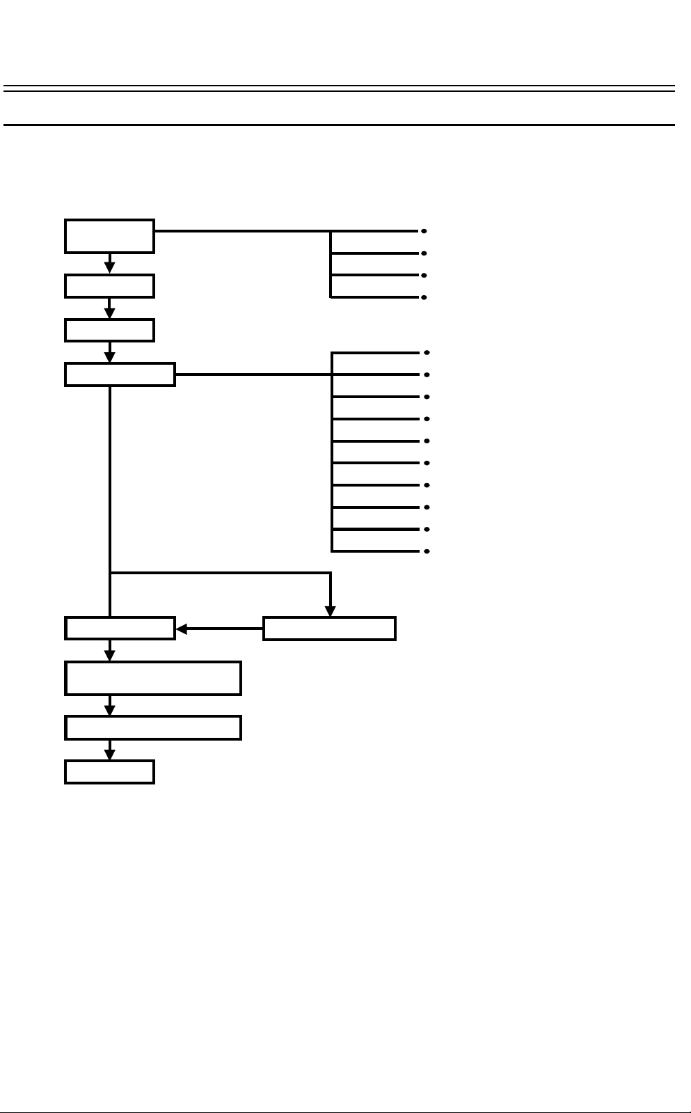
1.1.1 Delivery and installation work flow
Installation
condition check
Delivery
Clamp removal
Main body setup
Machine power on
Installation environment, floor strength
Space around machine, delivery route
Power supply
The user’s acceptance of the limited items
for using the machine (See User Guidance
Items section for the limited items.)
Supply developer
Supply cleaning carrier
Set OPC belt
Supply silicon oil
Install power plug and cord
Leveling
Installing original stacker
Installing sub-tray
Installing toner cartridge
Setting copy paper
Installation of peripherals
Operation check as far as the
machine stand-by condition
Machine operation check
User guidance
1-1
Page 7

Installation Requirements 1 July 1994
1.1.2 Environment
Select the conditions which fully satisfy the following items at installation.
Avoid a place exposed to direct sunlight or other strong light (should be below 1500 lux).
1.
Avoid locations wit h hi gh tem pe r at ure s or hi gh hum id it y, or low te mp era tu r es and low
2.
humidity. (Standard ran ge of te mp era ture and humidity: 10
Avoid places with hot air or strong heat sources.
3.
Avoid locations subject to abrupt temperature changes.
4.
Avoid small or dusty roo ms .
5.
Avoid poorly ventilated locations. (Air turno ve r sho ul d be 3 tim es or more per ho ur pe r
6.
person.)
Install the machin e flat on the floor. It must be level within 5 mm front to rear and 5 mm left
7.
to right. This is mainly to prevent affecting the tracking operation of the OPC belt.
Align the position of the LCT and finisher with the copier. First, adjust the height of
8.
peripherals on the basis of the exterior covers position. Finally, align the paper transport
guide plate height between each unit. This is to prevent paper misfeeds where each unit
connects.
The unit must be insta lled on a floor which can support its total weight : copier including ADF
9.
482 kg, finisher 77 kg, and LCT 75 kg.
Provide enough space, 100 cm in front, 60 cm in rear and 30 cm on both side s for operation
10.
and service. No fluorescent lights should be installed above the operation unit. (This is to
make it easier to see the operation display.)
o
C to 30oC, 15% to 90%)
1.1.3 Power connection (For the European version machine only)
Plug
1.
The plug must be approved under the TÜV safety standard and for a three-phase power supply.
Power supply cord
2.
The cord must b e approved unde r the TÜV safety standard and have five wire s inside. The
cross-sectional area of ea ch wire must be 2. 5 mm
be 14 to 18 mm. (The capa city must be over 6 00 volt s and 16 A for each ph ase. ) The lengt h
must be 5 m or less even if an extension cord is use d.
2
, and the outside diameter of the cord must
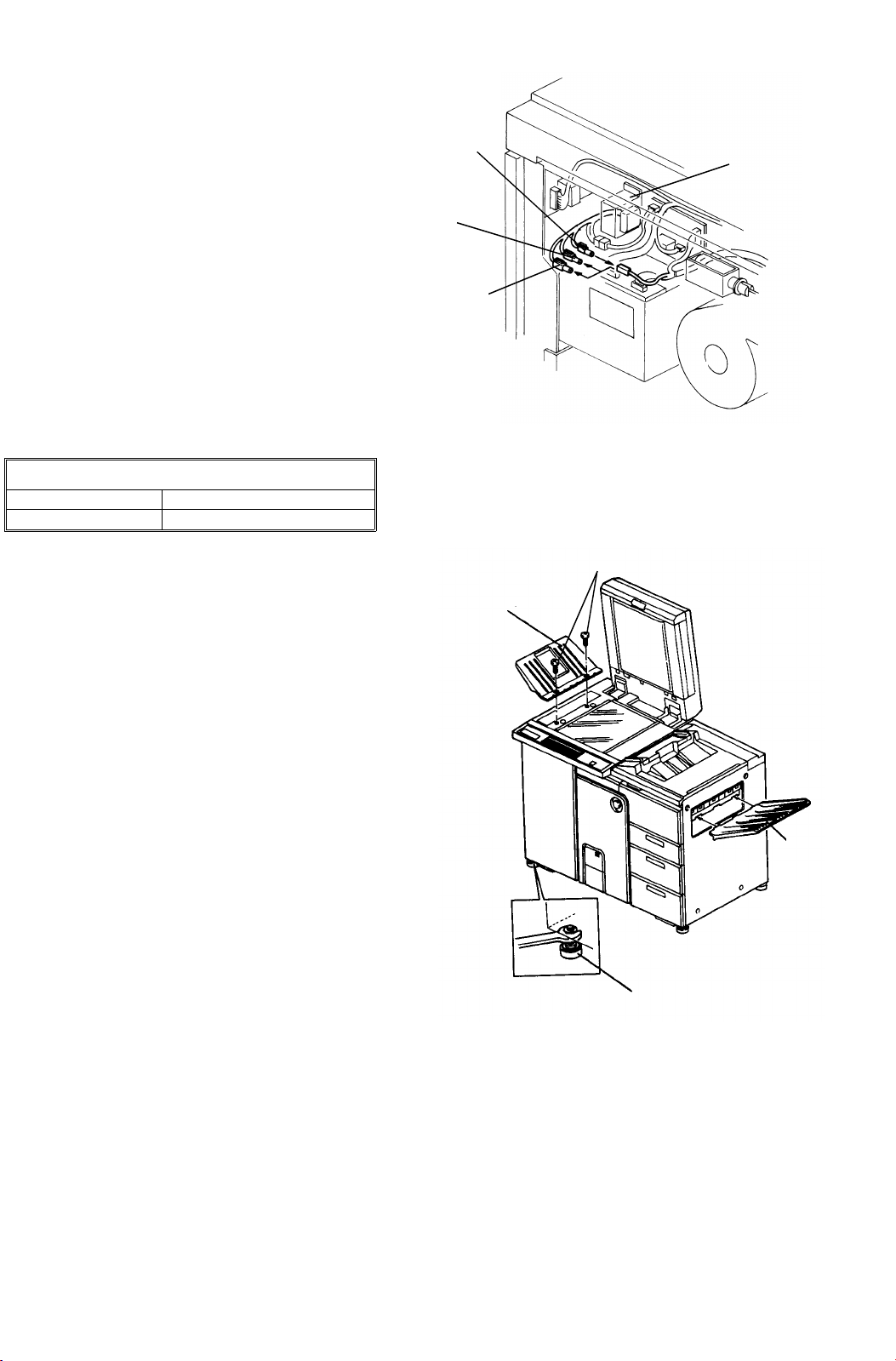
1.1.4 Transportation
Remove the operation unit before
transporting the copier if the copier cannot
get into the elevat or or co py room . Thi s
reduces depth to 775 mm from 830 mm.
Remove the cardboard packing in advance.
Remove four screw s (M4 x 6) from the operation
1.
unit.
Remove the connector for the operation unit and
2.
remove the operation unit.
CAUTION
Never carry the copier side down.
Connector
1-2
Operation unit
4 screws (M4 x 6)
Page 8
1 July 1994 Copier Installation
1.2 Copier Installation
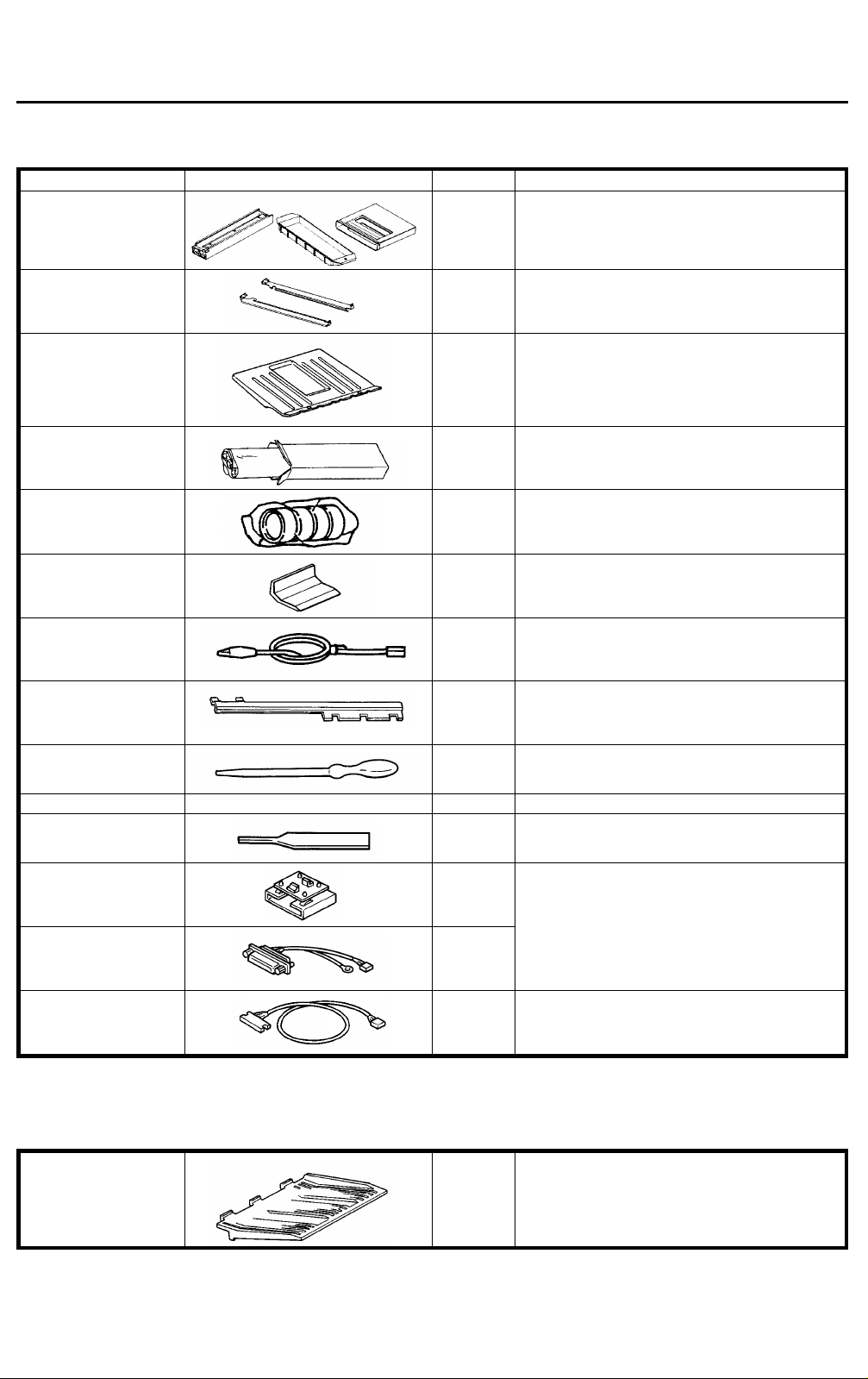
1.2.1 Accessory list
Name Diagram Quantity Use
Developer vessel
Cleaning carrier vessel
Cleaning carrier magnet
1 of each To collect the developer and cleaning carrier.
Vessel rail
Original stacker
OPC belt
Leveling shoe
Original back fence
Development unit
grounding harness
Tray fences fixing plate 3 To fix the paper tray side fences.
Syringe
2 To set the developer vessel.
1 To receive originals from the ADF.
1
4 For the docking position adjustment.
1 To install on the original stacker.
1 To avoid damage of the image density sensor board
when a vacuum cleaner is used.
1 To apply silicon oil in the fusing unit.
Plated screw M 4 x 8 4 To secure the vessel rails.
Counter reset key
Printer interface board 1 To connect a printer using service tool [6]. These
Short printer harness
Long printer harness
1 To reset the total counter to 0.
parts are needed when the optional printer
connector unit is installed. Keep these parts for
future use.
1
1 To connect a printer using service tool [6].
NOTE
When the optional fin is he r is no t us ed , the sub-tray (P/N-A029146 0) mu st be ord ere d and used.
Sub-tray 1 To receive copies fed out. (Not required when the
sorter is used.)
1-3
Page 9
Copier Installation 1 July 1994
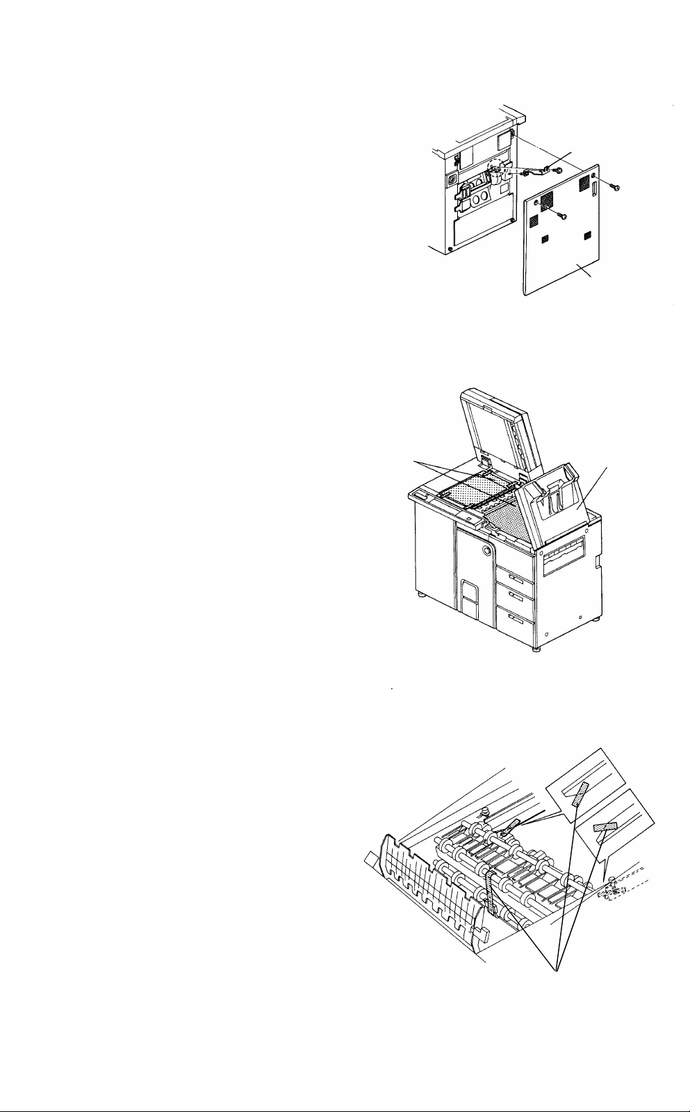
1.2.2 Removing the clamps
ADF
Remove the cushions from the paper feed tray, the
1.
cushion from the co py tray, and the strips of
filament tape from the exterior.
Cushions (2)
Cushion Cushions (3)
Open the center door and remove the 7 strips of
2.
filament tape and a cushion from the transport unit.
Remove the right cover (2 screws). Then, remove
3.
the clamps from tray 1, tray 2 and tray 3 using a
slot head screwdriver.
Center door
Cushion
Clamp
Right cover
1-4
Page 10
1 July 1994 Copier Installation
Take off the left cover and remove the red bracket
4.
holding the second mirror.
Remove the protective sheets of the expo sure
5.
glass and copy tray.
Protective sheet
Holder bracket
Copy tray
Remove the strips of filament tape from the duplex
6.
unit.
Filament tape
1-5
Page 11
Copier Installation 1 July 1994
To remove the inner cover, remove the left door
7.
fixing screw (2 screws), and di sc on ne ct the cooling
Left door
fan connector.
Cooling fan
connector
Inner cover
Remove the first mirror bracket (red bracket).
8.
To enable accessing the service tool password,
9.
turn on DIPSW101-2.
Remove the OPC cleaning unit fixing screw to pull
10.
Mirror
bracket
out the unit, and cut the unit fastener.
To pull out the fusing unit, remove the front fusing
11.
cover (2 screws) and one unit fixing screw.
Remove the cover from the right side of the unit (4
12.
screws).
Loosen the pressure fixing screws to remove the
13.
wedges on the front and far side. Re-tighten the
pressure fixing screws.
Install the fusing right side cover.
14.
NOTE
Install the front fusing cover after pouring silicon oil.
Peel off the plain sheet behind the fusing oil pan.
15.
Unit fixing screw
Unit fixing screw
(before removal)
Front fusing cover
Wedge
Unit fixing screw
Unit fastener
Wedges
Pressure
fixing screw
Pressure fixing screw
1-6
Sheet
Page 12
1 July 1994 Copier Installation
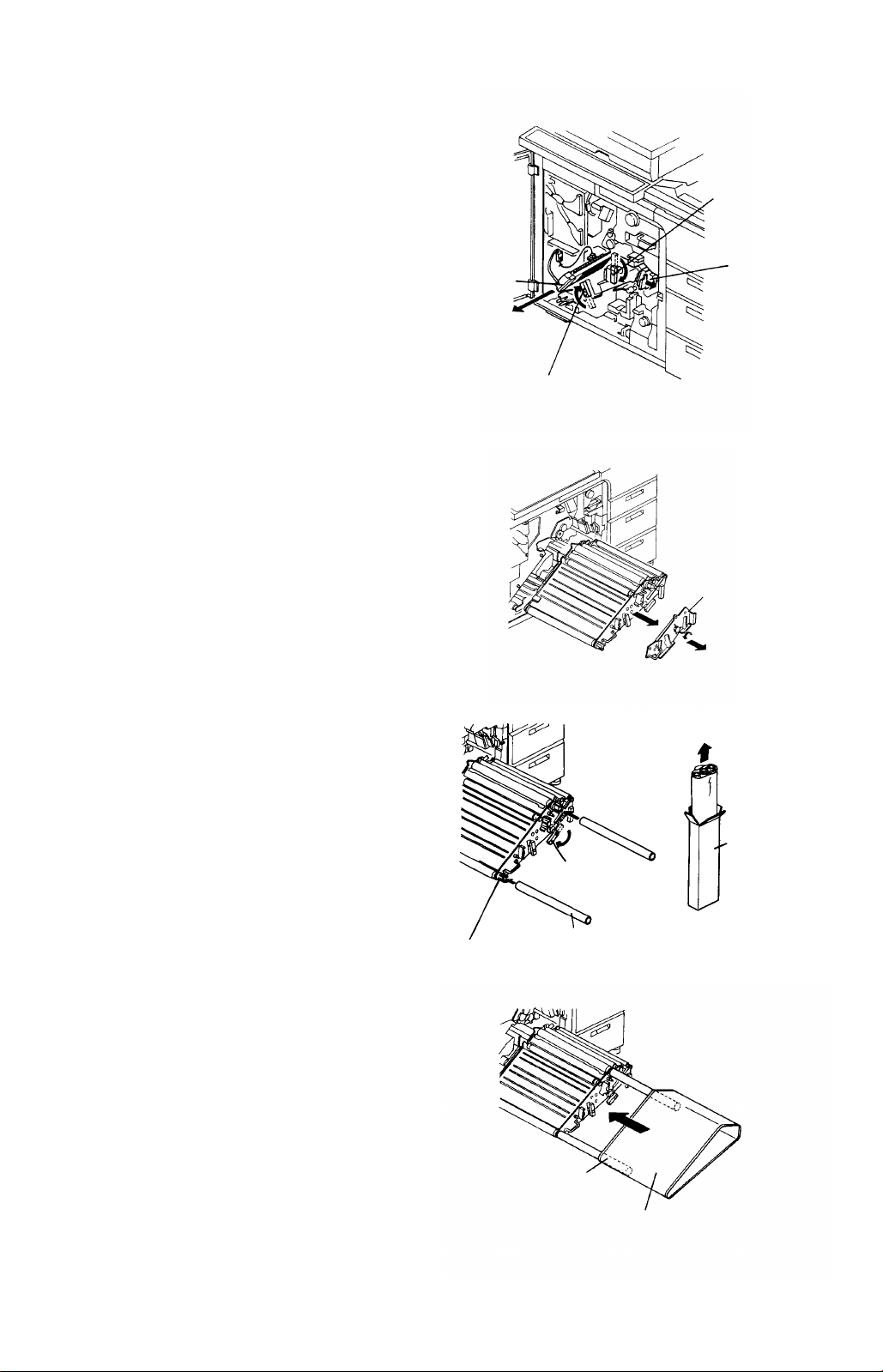
1.2.3 Setting up the copier
Release the development backup rollers by the
1.
lever, and remove the development unit fixing
bracket. Then, slide out the unit.
Development
backup lever
Fixing bracket
Remove the filter cover from the developer supply
2.
port (2 screws). While turning the development
knob in the direction opposite to the arrow, put in 4
bags (1 kg/bag) of developer from the supply port.
CAUTION
• Clean off the developer on the unit casing.
It may touch the OPC surfa ce.
• Do not put in another compound (cleaning
carrier, etc.) by mistake.
Filter cover
Developer
Developer
supply port
Casing
Reinstall the fi lter cover.
3.
Turn the development knob in the direction of the
4.
arrow and return the developer from the
development roller to the unit inside.
Development knobDevelopment knob
Filter cover
Development knob
1-7
Page 13
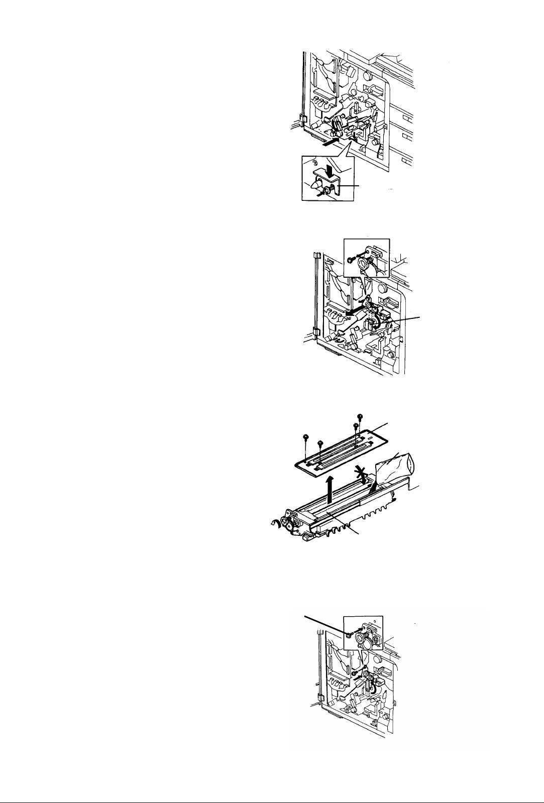
Copier Installation 1 July 1994
Slide in the development unit, and fix it with the
5.
fixing bracket.
Fixing bracket
Release the cleaning backup roller by the lever,
6.
Cleaning fixing screw
and remove the cleaning fixing screw to pull out
the cleaning unit.
Remove the upper cover from the cleaning unit (4
7.
screws). Put in one bag of cleaning carrier (700 g)
on the cleaning roll er (rig ht sid e of t he uni t).
CAUTION
• Be sure that the carrier is not in the
scavenging roller side.
• Do not put in another compound by
mistake, such as developer, etc.
• Distribute the carrier evenly by turning the
knob. This unit has no agitation mechanism
as the development unit does.
Upper cover
Cleaning carrier
Cleaning roller
Cleaning
backup lever
Close the upper cover, set the unit in the main
8.
body, and secure it with the fixing screw.
Fixing screw
1-8
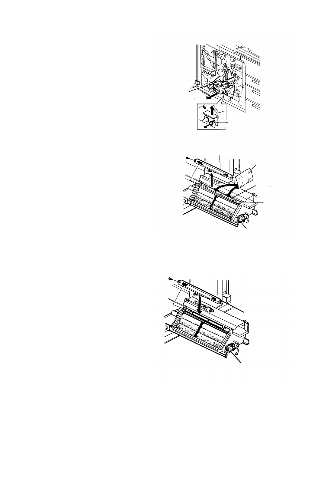
Page 14
1 July 1994 Copier Installation
Pull out the charge corona unit, and release the
9.
transport unit.
Release the development and cleaning back-up
10.
levers, and turn the development knob in the
direction of the arrow. Then, remove the OPC unit
stay to pull out the OPC unit.
CAUTION
Charge corona unit
Development back-up lever
Cleaning
back-up lever
Transport unit
Be sure to return the developer from the
development roller to the inside of the unit
before pulling out the OPC unit. Do this by
turning the development knob.
Insert two paper tubes (OPC belt accessories) in
11.
the two guide holders of the OPC unit. Then,
release the pressure rele as e le ve r t o lo os en the
tension, and pull the OPC belt out of the case.
Use the paper tubes as guides to fit the OPC belt
12.
to the unit.
CAUTION
• As you fit the OPC belt, be sure to prevent
folds and contact between the side plate of
the OPC unit and the belt end. Do not
touch the OPC surface directly.
•
Set the OPC belt so that the OPC home
mark is on the rear side of the machine.
• The rear side of the OPC belt must be und er
the OPC sensor.
Guide holder
Pressure
release lever
Paper tube
OPC home
mark side
OPC unit stay
OPC belt case
OPC belt
1-9
Page 15
Copier Installation 1 July 1994
Set the OPC belt in the center of the unit and
13.
restore tension to the belt with the pressure
release lever.
Pressure release lever
OPC sensor
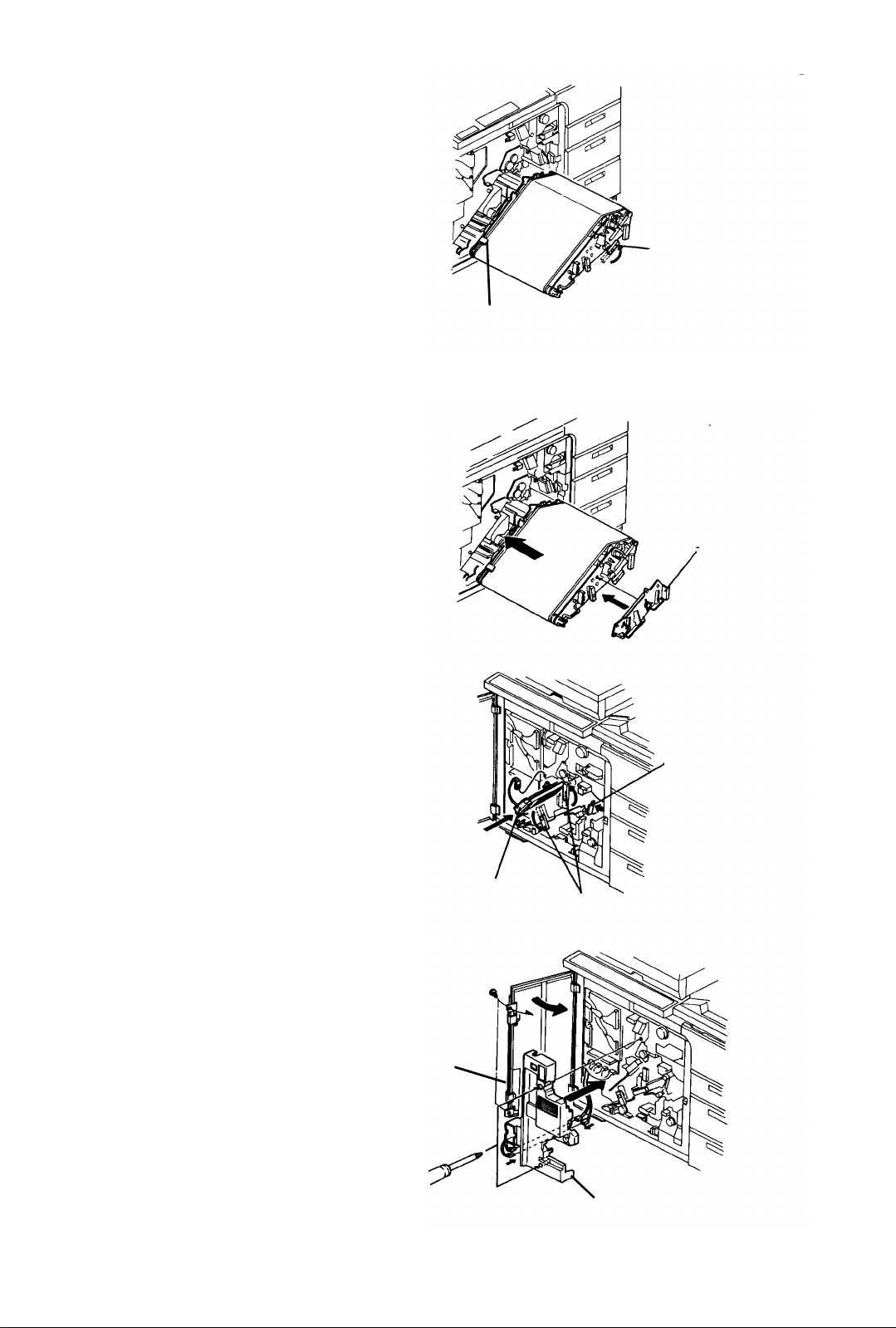
Set the OPC unit in the main body and install the
14.
OPC unit stay.
Set two backup levers, and position the charge
15.
corona unit, its connector, and transpo rt unit.
Install the inner cover (2 screws and a connector)
16.
and left door (2 screws).
Charge corona unit
OPC unit stay
Transport unit
Backup levers
Left door
1-10
Inner cover
Page 16
1 July 1994 Copier Installation
Pull out the fusing unit and remove the front fusing
17.
cover.
Put silicon oil in the oil sump. About 80 g of oil is
18.
sufficient.
Install the front cover and set the unit in the main
19.
body.
Put two cans of silicon oil in the oil tank. (2/3 of
20.
capacity make s ab out 200,000 copies .)
CAUTION
Never remove the oil supply unit from the fusing
unit to prevent oi l marks on copies. It can be
removed only when the oil blade, metering
blade, and oil supply felt are replaced with new
ones.
Oil tank
Tighten the screw (M4 x 8 plated screw:
21.
accessory) on the rear of the vessel rails
(accessories). Put the screws in the hole at the
bottom rear of the machine frame.
Fit the vessel rails on the bottom of the machine,
22.
and secure each of them with the screw (M4 x 8
plated screw) from the front of the machine. Set
the developer vessel (accessory) on the rail. Put
the cleaning carrier vessel and magnet (both
accessories) in the developer vessel.
Cleaning
carrier vessel
Cleaning
carrier magnet
Vessel rail
Developer vessel
1-11
Page 17
Copier Installation 1 July 1994
European version machine only (Steps 23 to 27)
CAUTION
The power supply cord and plug for the
European version machine must meet the
following requirements:
•
The plug must be approved under the TÜV
safety standard and for a three-phase
power supply.
• The cord must be approved under the TÜV
safety standard and have five wires inside.
The cross-sectional area of each wire must
be 2.5 mm
cord must be 14 to 18 mm. (The capacity
must be over 600 volts and 16 A for each
phase.) The length must be 5 m or less
even if an extension cord is used.
2
, and the outside diameter of the
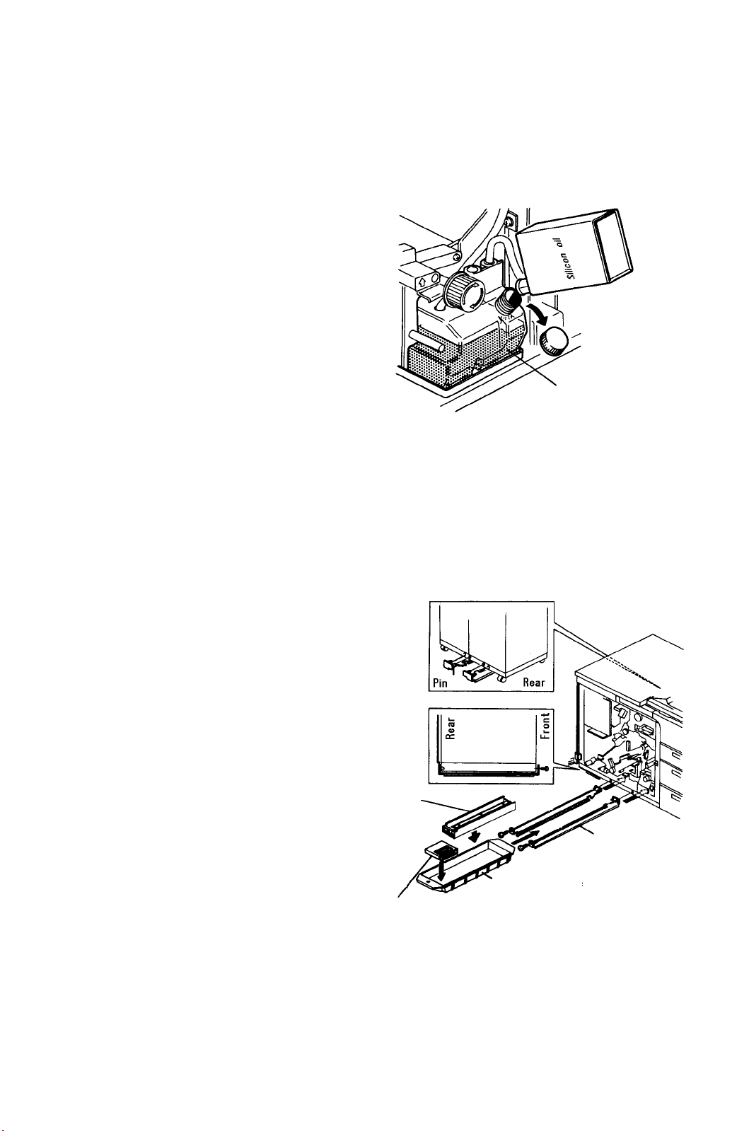
Remove the rear left cover (2 screw).
23.
Remove the power supply cord bracket (2 screws).
24.
Then, pass the power supp ly cord t hro ug h th e co rd
bushing.
Connect the five wires of the power supply cord to
25.
the appropriate terminals as shown.
CAUTION
• Secure each wire to the terminals firmly
with screws.
• The grounding wire is green and yellow.
Reinstall the power supply cord bracket. Then,
26.
tighten the nut to secure the bushing with the cord.
CAUTION
Be sure that the cord bu shin g se cures the cord
firmly.
Install a plug on the other end of the power supply
27.
cord.
CAUTION
• Connect five wires to each of the terminals
’L1’, ’L2’, ’L3’, ’N’, and "Grounding" in the
same order as on the machine.
•
Secure each wire to the plug firmly with
screws.
The machine is set up for a 400 volts 3-phase
power supply (Eu ropean version) or 240 vo lts
single phase powe r supply (U.S.A. ver sion) at
the production li ne. To install the machine in
areas where the power supply is 380 or 415 volts
(220 or 230 volts single phase), follow the steps
below:
Loose the screw and disconnect the wire from the
28.
400 volts (or 240 volts) terminal.
Connect the wire to an appropriate terminal and
29.
tighten the screw. The terminal to be connected
depends on the power supply from the wall outlet.
CAUTION
The 200 volts terminal ne ver be used. The copier
requires 380 volts (or 220 v olts sin gle pha se) at
least.
Cord fixing nut
220 or
380V
230 or
400V
240 or
415V
Cord bushing
Power supply cord bracket
1-12
Page 18
1 July 1994 Copier Installation
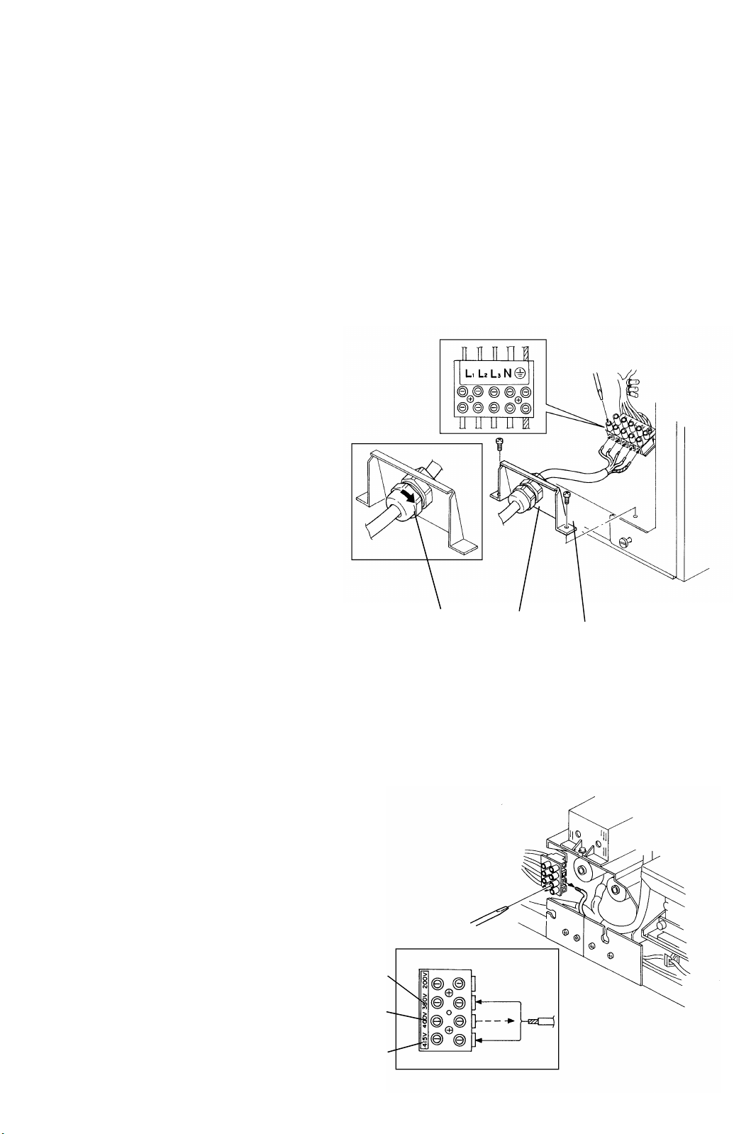
Remove the rear right cover (2 screws).
30.
Be sure that the proper connector of the harness
31.
from the timer board is set. The color of each
connector means the following:
Black: for 380 or 220V power su pp ly
Red: for 400 or 230V power supp ly
Red
connector
Black
connector
Timer board
transformer
Yellow: for 415 or 240V power su pp ly
If the connector setting does not meet the power
32.
supply, connect an appropriate connector.
Yellow
connector
Set the leveling shoes (accessories) to level the
33.
machine.
STANDARD
Difference, front to rear Within 5 mm
Difference, left to right Within 5 mm
Screws securing
upper left cover
CAUTION
Using a level gauge, level the machine flat on
Original stacker
the floor. This is mainly to pre vent affectin g the
tracking operation of the OPC belt.
Install the exterior covers.
34.
NOTE
Do not install the exterior covers at this stage if the
finisher or LCT is to be installed.
Fit the original stacker (accessory) and sub-tray
35.
(must be ordered separately if necessary). To fit
the original stacker, use screws which secu red the
upper left cove (M4 x 12 plated screw).
Put the original back fence (accessory) on the
36.
original stacker.
NOTE
The sub-tray i s no t req uired if the fi nish er is u sed.
It is installed i n the LCT if the LC T is us ed and the
finisher is not.
Sub-tray
Leveling shoe
1-13
Page 19
Copier Installation 1 July 1994
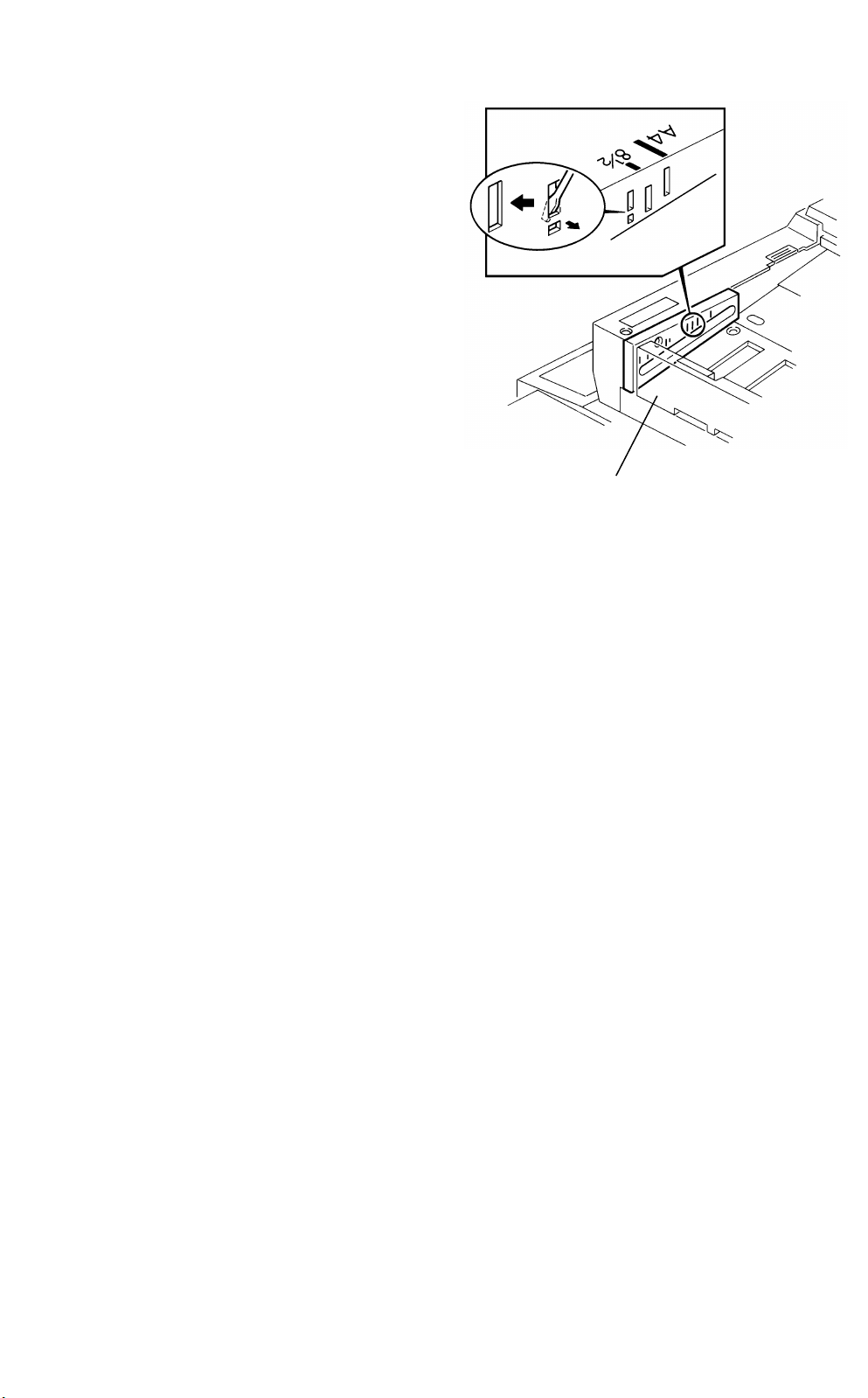
When inch size originals are used, make a slot as
37.
shown to stop the original stopper at the 8
1/2
inch
position.
CAUTION
When the slot is made, opera ting cautions must
be instructed to operators, so that operators
can adjust the original stopper position
correctly according to the original size set in the
ADF. The A4 position and 8
1/2
inch position are
very close. If the o riginal stopp er position is not
proper, original misfeeds will occur.
Set the toner cartridge.
38.
CAUTION
Shake the toner cartridge well be fore you s et it.
Set paper in each paper tray.
39.
CAUTION
Original stopper
Do not block the fan filter windows of the left
and rear exterior covers.
1-14
Page 20
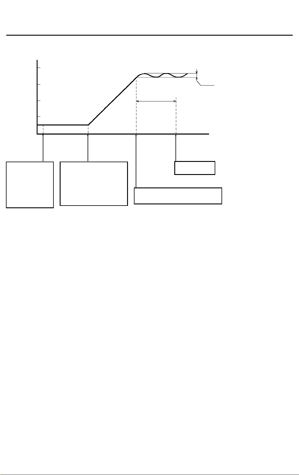
1 July 1994 Machine Operation Check
1.3 Machine Operation Check
1.3.1 Stand-by operation check
200
Fusing Temp.
[° C]
100
Power
connection
The cleaning coil
cooling fan, two
ozone exhaust fans
(behind the rear left
cover), and
cleaning unit
cooling fan (behind
the left cover) start
turning.
Main switch
ON
1. Configuring the first and
second mirrors.
2. The fusing heater ON.
3. The OPC belt ON (2 turns).
4. The Tracking motor ON .
5. All the fans ON except for
the duplex and ADF blowers.
1.3.2 Copier operation check
CAUTION
175 ° C
175 to 180 ° C
Approx.
30 sec.
The Start key
turns green.
The idling mode starts (30 seconds).
The main motor repeats turning on and
off four times during this period.
Before making copies, carry out forming for the developer, OPC belt, and cleaning
carrier (in this order) using service tool [3-04].
1.
Check the stand-by operation referring the above. Connect the power plug, then turn on the
main switch.
2. Access the service tool, and do all formings.
3. Check that all the keys on the operation panel and paper tray down keys work properly.
4. Check that safety switches of the center door, upper right door, and copy tray work properly.
5. Place a sheet on the original table of the ADF and check that the ADF mode is selected.
Also, insert a sheet in the SADF table and check that the SADF mode is selected.
1-15
Page 21

Machine Operation Check 1 July 1994
1.3.3 Copy quality check
CAUTION
Before checking copy image quality, check the toner density control data in the
service tool [4-02] screen. Perform setting C if the data is not correct. Also, check the
AID reference voltage in the [4-03] screen using the PC-1 chart. Perform setting A if
the value is not correct. (If the AID reference voltage is within the standard, you do
not have to perform setting A.)
1.
To check the copy image quality and paper transportation in the copier, make some copies
in the platen cover (no ADF and SADF) and AID (Auto Image Density) modes using a test
chart.
2. Follow the steps below to complete the image quality adjustment. (Refer to the following
page for the standards.)
1) Position a test chart on the exposure glass. Make copies to check the side-to-side registration.
Adjust it by changing the paper tray position, if necessary. Repeat this step for all paper trays.
2) Select the paper tray which has the largest paper size.
3) Access the service tool and select the [5-02] screen. Check and adjust all items in that screen.
4) Leave the service tool, and select the paper tray which has another paper size.
5) Again, check and adjust the erase margin and duplex side fences width on the [5-02] screen.
Repeat this step for each paper size which will be used by the customer.
6) To check and adjust the side-to-side registration of the back side of the copy, make copies
in the duplex mode.
7) Remove the test chart from the exposure glass and insert an original in the SADF. Make
copies to check and adjust the leading edge and side-to-side registration in the SADF mode.
8) Place some originals in the ADF. Make copies to check and adjust the side-to-side registration
in the ADF mode.
CAUTION
a) The side-to-side registration must be checked for all paper trays.
b) The erase margin and duplex side fence width must be checked for all paper sizes.
c) If the erase margin is not sufficient, thin black lines may sometimes appear on
copies (especially on the side edges of copies in the ADF mode). This is because the
side-to-side registration varies slightly on each copy if an operator does not set the
original side guides securely. You have to make more than 10 copies and check that
all of them are within specifications after the adjustment.
d) Check the side-to-side registration of the back side of the copy in the duplex mode
before installing the peripherals. If the value is outside specifications, you have to
remove the copier right cover.
3.
Put about 20 originals on the ADF and make one set of copies in the single original duplex
mode. Repeat this procedure for all paper trays.
4. Put about 100 originals on the ADF and make one set of copies in the 2-sided original du-
plex mode.
5. Insert an original in SADF and check that copying is normal.
6. If peripherals are installed, check that they works properly.
1-16
Page 22
1 July 1994 Table of Image Quality Standards
1.4 Table of Image Quality Standards
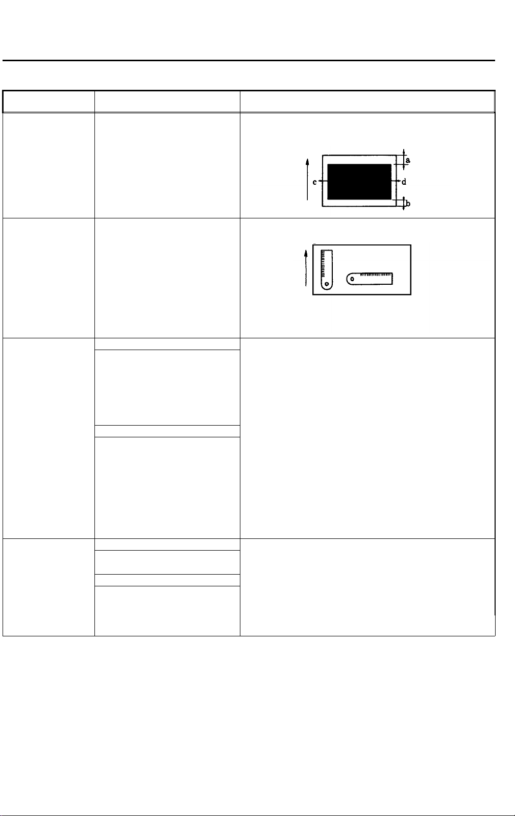
Item Standard Measuring Method
Erase margin a) Leading edge 1
b) Trailing edge 1
c) Left side edge 1
d) Right side edge 1
< c+d ≤ 7 mm
2
≤a≤7 mm
≤b≤5 mm
≤c≤5 mm
≤d≤5 mm
Make one solid black copy and measure blank dimensions at four
edges. After the adjustment, make more than 10 copies and check
the variation.
Error in magnification In full size mode: Within
In magnification mode: Within
Registration Platen cover mode
a) Leading edge: 0
b) Left and right edges: 0
These values also valid on the 2-sided
copy.
ADF/SADF mode
a) Leading edge:
--3 to +5 mm (ADF mode)
--4 to +6 mm (SADF mode)
b) Left and right edges: 0
The difference of the side-to-side
registration between the front and
back side must be within 5 mm.
± 2 mm
± 0.5%
± 2 mm
± 5 mm
Copy a scale and measure copy dimensions.
±1.0%
Copy a test chart and compare the image position difference
between the original and the copy. After the adjustment, make more
than 10 copies and check the variation.
Skew Platen cover mode Copy a test chart and compare the image position difference
± 1 mm/200 mm or less. between the original and the copy.
a)
ADF/SADF mode
± 1.5 mm/100 mm or less (on
a)
smaller than A4/Letter paper).
± 1 mm/100 mm or less (on
b)
A4/Letter or larger paper).
1-17
Page 23
User Guidance Items 1 July 1994
1.5 User Guidance Items
This section contains important information regarding efficient operation of the machine.
1.5.1 Guidance items prior to the installation
Items requiring user approval after explanation. This has to be done before machine installation.
Paper to use
1. We recommend using neutral paper as copy paper to prevent abnormal images. Some acid
papers contain talc, and this white powder will appear on the OPC surface as spots. This
causes abnormal copies, which have dirty spots on the background.
2. We recommend using lengthwise grain in all cases to prevent creased copies.
How the original influences copy images
1. In patched originals, shadows around the patched part appear on copies as black lines.
2. In OHP originals, drawn pictures and characters are copied double.
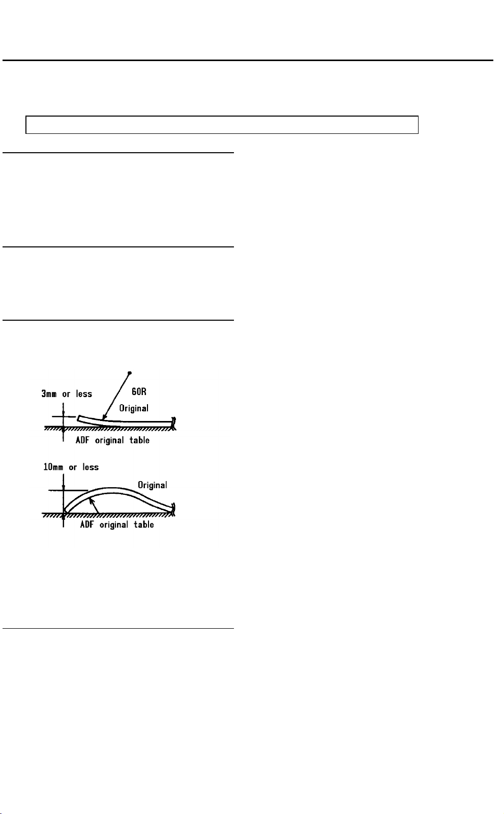
Smoothing original curls
To avoid transport trouble, advise users to correct large curls before setting the original. Refer to
the illustrations and information given below.
Face curl (3 mm or less)
No curl is acceptable for thick
originals of 65 g/m
Back curl (10 mm or less)
1.
The original cannot be transported if it curls (face curl).
2
or heavier.
2. The original cannot be transported if it curls down (back curl) 10 mm or more.
Original to use
There are some types of paper that should not to be used as originals with the ADF. The following
are some examples:
1. Dog-eared, torn, or creased paper
2. Coated paper (carbon paper, thermal paper, etc.)
3. Curled paper
4. Originals that are glued or taped
1-18
Page 24
1 July 1994 User Guidance Items
5. Translucent paper (including OHP)
NOTE
The above types of paper may be used as an
original in the SADF mode.
6. Damp paper
7. Bound originals
8. Paper that is thicker or thinner than specified for this machine
Originals that have holes as shown cannot be used in
the ADF mode.
A: No holes are allowed on the leading
edge. (To prevent multifeeding.)
B: No holes are allowed in these areas.
(The recycle arm may be caught in the
holes.)
C: Holes larger than 6 mm in diameter are
not allowed on the trailing edge.
D: Holes larger than 10 mm in diameter are
not allowed in the center. (To prevent sensor’s misdetection.) This type of paper cannot be used in the SADF mode either.
[Leading edge]
[Leading edge]
A
100 mm
100 mm
10 mm
B
C
D
B
10 mm
50 mm
Paper replenishment
When the 2nd or 3rd paper tray runs out of paper and the indication Add paper lights in red, this
means there are still about 50 sheets of paper left in the tray.
Fusing oil
The pick-off pawls of the fusing unit sometimes make slight oil marks on the leading edge of copies .
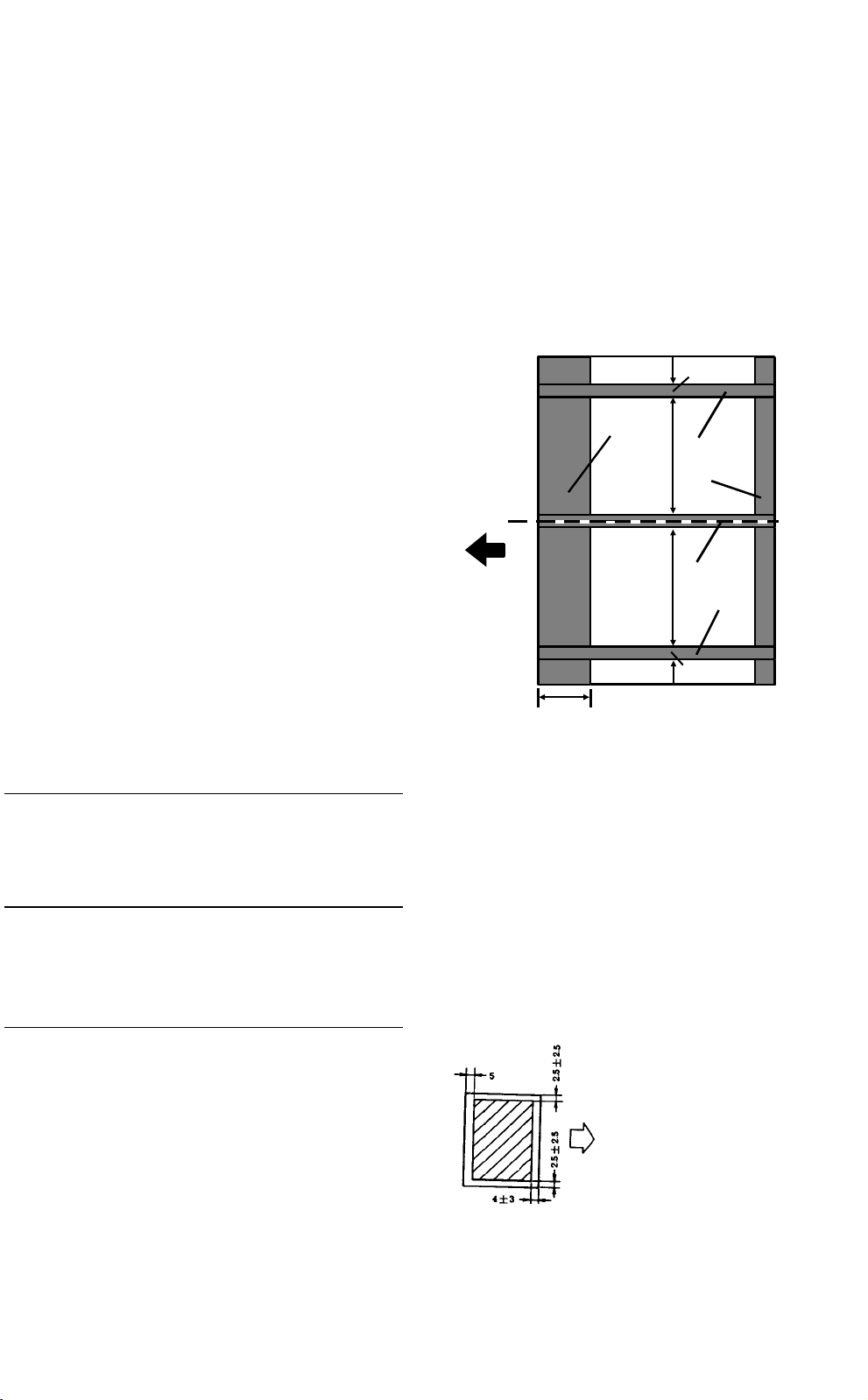
Copy image area
1. The blank range is provided as shown to prevent
original shadows on copies.
2. Damp copy paper will have an 8 mm blank margin
(or less) at the trailing edge of the front side, and if
duplex copying, the back side will have a blank
margin of 10 mm (or less) at the trailing edge.
Total of left and right
should be 7 mm or
less.
1-19
Page 25

User Guidance Items 1 July 1994
1.5.2 Additional guidance items
Explain the following if the user is unfamiliar with the subject items.
Stacking duplex copies
When a large number of duplex copies (100 copies or more) are produced, we recommend using
the finisher so they are stacked in the shift tray because toner from the stacked copies on the copier’s copy tray may be deposited by heat.
How the main switch is used
The ozone exhaust fans and transport vacuum fan continue to operate when the main switch is
OFF to discharge air from the machine. This prevents image deterioration on the OPC caused by
fumes, which is produced by the corona discharge. Also, heaters turn on when the main switch is
OFF and prevent condensation on the mirror and lens and damp paper in trays. Advise users never
to pull out the power plug or shut off power from the source. Tell them to use the main switch to
power off.
Toner cartridge replacement
Used toner is collected in the toner cartridge and is never used again because it cannot be used for
copying. Direct users about the following points.
1. Never pull the shutter again after the cartridge is set. If the shutter is pulled, the collected
toner is used again.
2. Firmly pull the vinyl sheet on the shutter when installing a new cartridge. If not, only about
half the amount of toner in the cartridge will fall to the development unit. This may cause a
used toner blockage on the way from the cleaning unit.
Loading paper
When loading paper in the paper trays, do not exceed the load limit. It is indicated by a decal. If paper is excessively loaded, the top of the paper stack may hit the pick-up roller and damage it when
the paper tray is set.
Loading original
When loading paper on the original table of the ADF, keep the maximum capacity (40 sheets for A3
or 11" x 17" original and 80 sheets for the other sizes original). The load limit is indicated by a decal. If originals are excessively set in the ADF, original misfeeding or multifeeding may occur because of the original separation system. The air knife cannot separate the originals when weight of
the original stack is too heavy.
1-20
Page 26
1 July 1994 Setting User and Service Tools
1.6 Setting User and Service Tools
Explain all user tool items and some of the service tools to the customer. Then, listen to the customer’s requests and set the copier accordingly.
Keep the set items using the following format. (If the main control board is replaced, you can set all
items again using the format.)
1.6.1 User tools
* Bold letters in "Set Data" shows the initial setting.
Menu
no.
1 Total sheets copied ---2 Auto image density level selection [Lighter] [Normal] [Darker]
3 Copy/Original size selection [A3] [11 x 17] [A4] [8
4 Segment skip ---5 Date/Time setting ---6 Disable display Margin adjustment [ON] [OFF]
7 Disable units ---8 Select special tray Cover [Tray 1]
9 User access code ----
10 User Utility Select the finisher mode [Sort] [Stack]
11 Set staple position 1 staple upper 0 to 20 [ ] 10
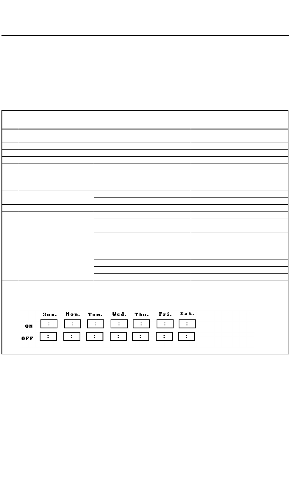
12 Weekly timer
Description Set Data
Duplex [ON] [OFF]
Magnification [ON] [OFF]
Slip sheet [Tray 1] [Tray 2] [Tray 3]
Staple in stack mode [Yes] [No]
Auto tray switching [Yes] [No]
3-side full image copy [Yes] [No]
Select count up or down mode [Up] [Down]
Display the number of originals [Yes] [No]
Exit originals to tray [Yes] [No]
Select face up/down in stack mode [Face up] [Face down]
Reverse back cover sheet [Yes] [No]
Copy onto slip sheets [Yes] [No]
1 staple lower 0 to 20 [ ] 10
2 staples 0 to 20 [ ] 10
ON: 00:00, OFF: 23:59
1/2 x 13]
1-21
Page 27
Setting User and Service Tools 1 July 1994
1.6.2 Service tools
* Bold letters in "Set Data" shows the initial setting.
Menu no. Description Set Data
1-01 Key operator access code 000 to 099 [ ] 000
1-02 Service access code 99900 to 99999 [ ] 99900
1-03 Service telephone number [ ]
1-04 Disable display Full size indicator: [OFF] [ON]
Tray keys in APS mode: [OFF] [ON]
Density keys in AID mode: [OFF] [ON]
1-05 Weekly timer This function can be set with user tool no. 12.
1-06 Toner supply amount [15%] [30%] [45%] [60%]
1-07 Charge wire cleaning [YES] [NO]
1-08 Option installation [Tray 4] [Finisher] [Key Counter]
2-01 Count up/down [UP] [DOWN]
2-02 Set user program number 0 to 10 [ ] 10
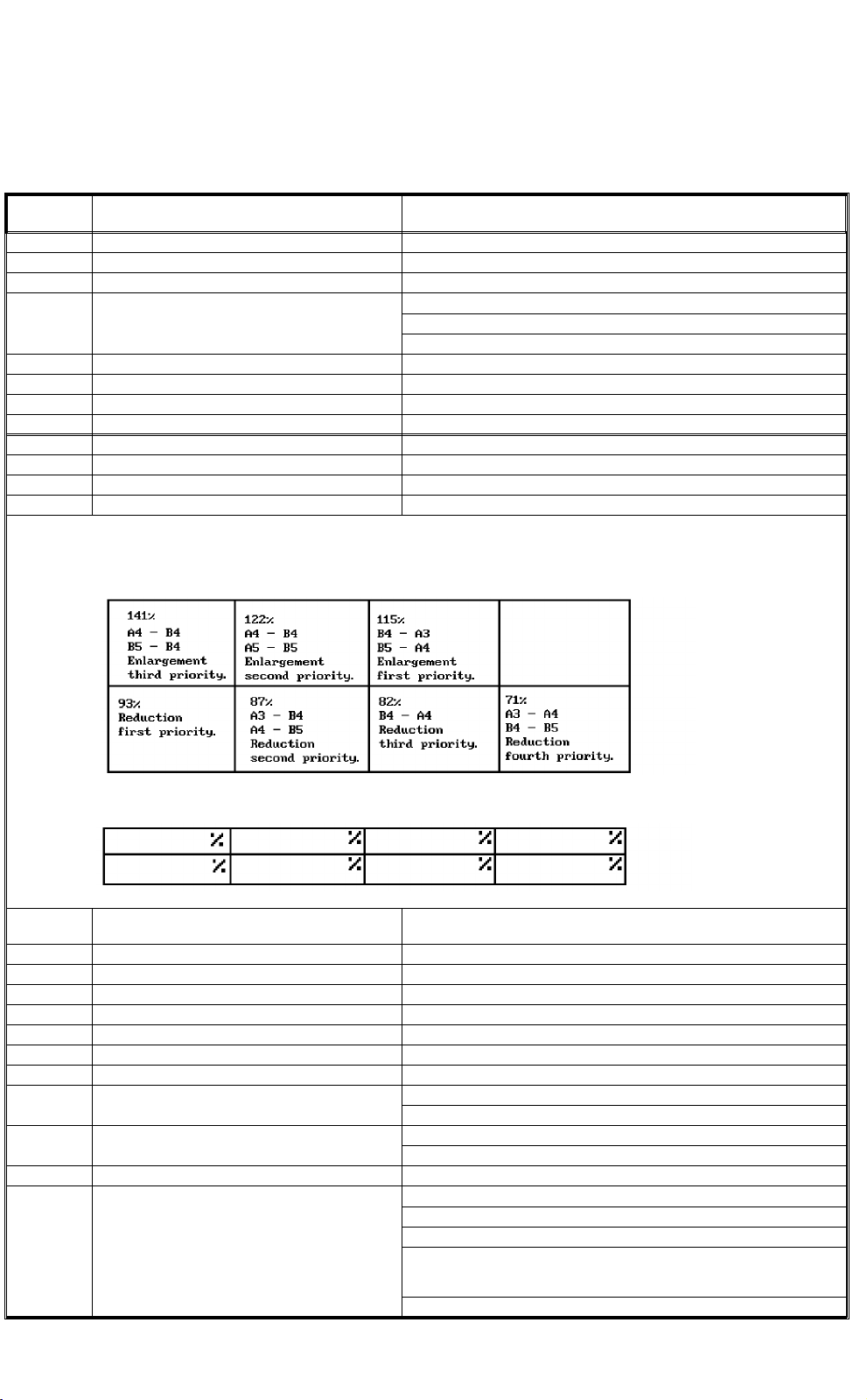
2-03 Set fixed reproduction ratios See the table below.
2-04 Delete fixed reproduction ratios No delete
[Initial Data]
[Set Data]
2-05 Set back side margin 0 to 21 mm in left or right.
2-06 Maximum copy number 1 to 9999 [ ] 9999
2-07 Staple copy limit 1 to 50 [ ] 50
2-08 Free/user access code operation [Free use][Access code] [Access code/super user mode]
2-09 3-side full image [YES] [NO]
2-10 Auto tray switching [YES] [NO]
2-11 Original count display [YES] [NO]
2-12 Set special paper tray [NO] [Tray 1] [Tray 2] [Tray 3] [Tray 4]
2-13 Auto reset , auto off Auto reset: [5 sec.] [1 min.] [3 min.] [
2-14 Key tone Loudness: [OFF] [Low] [Normal] [High]
2-15 Set exit tray copy limit [300] [350] [400] [NO]
2-16 Set initial display Display type selection: [Key operator] [Operator]
[ ] mm [Left] [Right] 5 mm Right
∞ ]
Auto off: [30 min.] [1 hr.] [3 hr.] [
Tone pitch: [1] [2] [3] [4] [5]
Auto tray selection: [YES] [NO]
Tray selection priority: [APS] [Tray 1] [Tray 2] [Tray 3] [Tray 4]
Image density level selection:
[AID]
Density levels [1] [2] [3] [4] [5] [6] [7]
Finishing: [No Staple] [1 upper] [1 lower] [2]
∞ ]
1-22
Page 28

1 July 1994 Setting User and Service Tools
Menu no. Description Set Data
2-16 Set initial display Margin adjustment mode selection:
4-01 Process control Grid: [ ] step
4-02 Toner density control Target toner density: [ ] volts
4-04 OPC cleaning operation [OFF] [5K] [10K] [20K] 10K
4-05 Utility Mode no. 1 (0 to 15): [ ] 0
[No]
Front side:
0 to 21 mm in left or right
[ ] mm [Left] [Right] 0 mm
Back side:
0 to 21 mm in left or right
[ ] mm [Left] [Right] 5 mm Right
Duplex mode selection:
[No]
⇒ Duplex mode]
[Single
⇒ Duplex mode]
[Duplex
⇒ Single mode]
[Duplex
Reproduction mode selection:
[Full-size]
Fixed reproduction [ ] %
Zoom reproduction [ ] %
Auto paper selection [A3] [B4] [A4] [B5]
Copies number setting: 1 t0 9999 [ ] 1
Flash: [ ] step
Bias: [ ] step
Pcc: [ ] step
VD: [ ] volts
VL: [ ] volts
VPCC: [ ] volts
ID pattern level: [1] [2] [3] [4]
Mode no. 2 (0 to 15): [ ] 10
Mode no. 3 (0 to 15): [ ] 0
Mode no. 4 (0 to 15): [ ] 0
Mode no. 5 (0 to 15): [ ] 0
Mode no. 6 (ON or OFF): [ ] OFF
Mode no. 7 (ON or OFF): [ ] ON-8, 10
Mode no. 8 (ON or OFF): [ ] ON-10
Mode no. 9 (ON or OFF): [ ] OFF
Mode no. 10 (ON or OFF): [ ] ON-9
Mode no. 11 (ON or OFF): [ ] OFF
Mode no. 12 (ON or OFF): [ ] OFF
Mode no. 13 (ON or OFF): [ ] OFF
Mode no. 14 (ON or OFF): [ ] OFF
NOTE: When mode no. 5 is set at 8 to 15, modes no. 6 to 14 have
different functions. So, describe the set number of mode no. 5 with
"ON" when filling in the set data of modes no. 6 to 14. For example, if
mode no. 6 is turned ON while mode no. 5 is set at 8, describe the set
data of mode no. 6 as "ON-8".
5-02 Copy image Lead/trail edge erase: Lead [ ] mm, Trail [ ] mm
Side edge erase: Front [ ] mm, Rear [ ]mm
Lead edge registration: [ ] mm
Reproduction: [ ] %
Duplex side fences width: [ ] mm
5-03 Fusing temperature 0 to 15 [ ] 8 or 9
5-07 Set staple position This function can be set with user tool no 11.
1-23
Page 29
Fusing
High
Voltage
Drive
Optics
Imaging
Process
Paper Feed
Du-
plex
Control
Develop-
ment
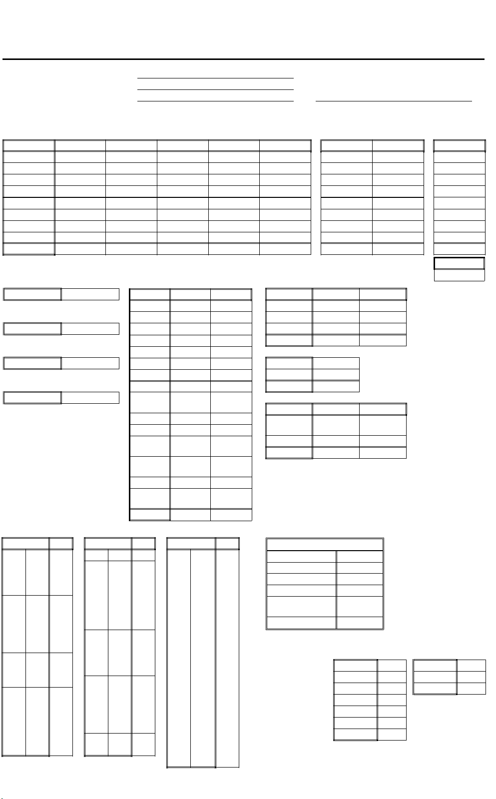
Logging Data Sheet 1 July 1994
1.7 Logging Data Sheet
[3-01] Tray Copies
Size Tray 1 Tray 2 Tray 3 Tray 4 Total Duplex Finisher RDH
A3 -------B4
A4
B5
Sub Total --------
11 x 17 --------
1/2 x 14
8
1/2 x 11
8
Total
[3-04] Supply yield
OPC
Developer
CL Carrier
Staple 1
[3-07] Service Calls
Code Code Code
1 36 80
2 40 81
3 41 82
4 42 83
10 43 84
11 44 85
12 45 86
13 50 87
17 51 88
20 52 89
22 55 90
23 60 91
30 61 93
31 62 94
32 63 95
33 64 96
34 70 97
35 71 98
Date:
Customer:
Serial No. Copy Counter:
[3-02]
Duplex/Finishing Copies
[3-05] Copier Misfeeds
Location ON OFF
Tray 1
Tray 2
Tray 3
Tray 4
Regist
Pick-off
Fusing
Sub Total
Duplex
gate
Exit gate
Exit tray
Horz.
Trans 1
Horz.
Trans 2
LCT Top
Duplex
Feed
Total
99
[3-06] RDH/Finisher Misfeeds
Location ON OFF
RDH Feed
RDH Trans
RDH Exit
Total
SADF Feed
SADF Exit
Total
Location ON OFF
Inverter
Unit
Finisher
Total
[3-08] Operation Time
Hours
Power ON
Fusing Lamp
Main Motor
OPC Belt Motor
Development
Motor
Wire Motor
Mark cleared item(s)
Developer
CL Carrier
[3-03]
Original Feeds
3-01 3-05
3-02 3-06
3-03 3-07
OPC
Staple 1
1-24
SADF
Page 30
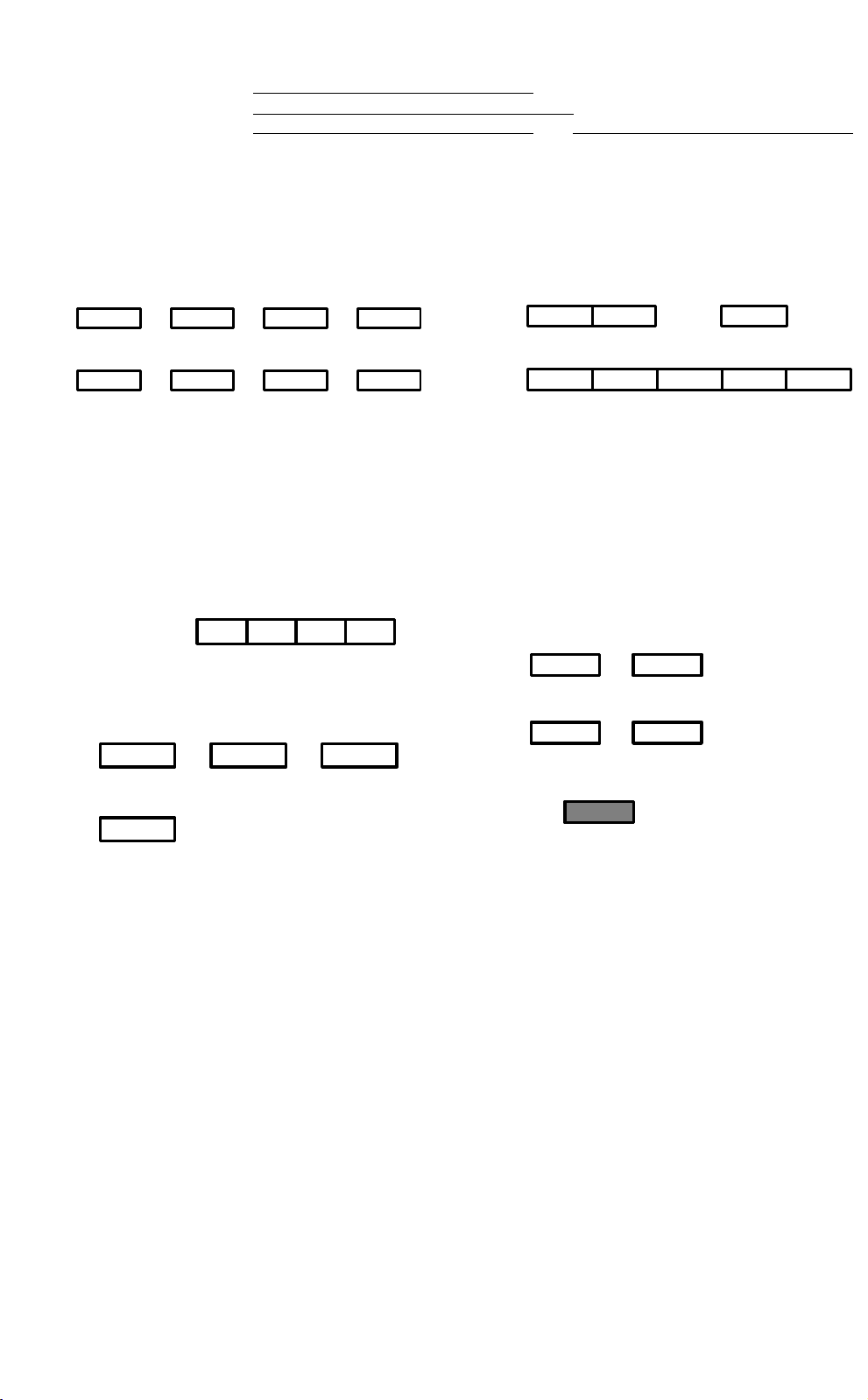
1 July 1994 Logging Data Sheet
[4-01] Process Control
Setting
Grid
(step)
Shift
(step)
Flash
[4-02] Toner Density Control
Date:
Customer:
Serial No. Copy Counter:
Bias
PCC
Target
(volts)
Actual
(volts)
VD VL VR
VPCC
ID
Sensor
Actual
SG/VSP
V
ID Pattern Level
SP
V
(volts)
Lighter
1 2 3 4
V
SG
(volts)
Darker
T. D.
Sensor
Setting
Actual
Developer
Forming
Target T. D.
(volts)
ON
Pattern
Potential
(volts)
1-25
Page 31

Logging Data Sheet 1 July 1994
Logging Data Sheet (Misfeeds)
Item
Mark for data clear
Tray 1 ON
Tray 2 ON
Tray 3 ON
Tray 4 ON
Regist ON
Pick-off ON
Fusing ON
Sub total ON
Duplex
Gate
Exit
Gate
Exit Tray ON
Horz.
Trans. 1
Horz.
Trans. 2
LCT Top ON
Duplex
Feed
Total ON
RDH Feed ON
RDH Trans ON
RDH Exit ON
Total ON
SADF Feed
SADF Exit
Total
Inverter
Unit
Finisher ON
Total ON
Date
Counter
OFF
OFF
OFF
OFF
OFF
OFF
OFF
OFF
ON
OFF
ON
OFF
OFF
ON
OFF
ON
OFF
OFF
ON
OFF
OFF
OFF
OFF
OFF
OFF
ON
OFF
OFF
OFF
Customer
Serial No.
1-26
Page 32

1 July 1994 Logging Data Sheet
Logging Data Sheet (Service Calls)
Item
Mark for data clear
1
2
3
4
10
11
12
13
17
20
22
23
30
31
32
33
34
35
36
40
41
42
43
44
45
50
51
52
55
60
61
62
63
64
70
71
80
81
82
83
84
85
86
87
88
89
90
91
93
94
95
96
97
98
99
Date
Counter
Customer
Serial No.
1-27
Page 33

Tray 1
Tray 2
Tray 3
Tray 4
Duplex
Finisher
RDH
Logging Data Sheet 1 July 1994
Logging Data Sheet (Copies/Originals)
Item Date
Counter
Mark for data clear
A3
A4
B5
11" x 17"
1/2 x 14"
8"
1/2 x 11"
8"
Sub total
A3
A4
B5
11" x 17"
1/2 x 14"
8"
1/2 x 11"
8"
Sub total
A3
A4
B5
11" x 17"
1/2 x 14"
8"
1/2 x 11"
8"
Sub total
A4
B5
1/2 x 14"
8"
1/2 x 11"
8"
Sub total
Total
A3
B4
A4
B5
11" x 17"
1/2 x 14"
8"
1/2 x 11"
8"
Total
A3
B4
A5
B5
11" x 17"
1/2 x 14"
8"
1/2 x 11"
8"
Total
A3
B4
A4
B5
11" x 17"
1/2 x 14"
8"
1/2 x 11"
8"
Total
SADF
Customer
Serial No.
1-28
Page 34

Operation Time
Supply Yield
1 July 1994 Logging Data Sheet
Logging Data Sheet (Others)
Item Date
Counter
Power ON
Fusing Lamp
Main motor
OPC Belt motor
Development motor
Wire Cleaner Motor
OPC
Developer
Cleaning Carrier
Staple 1
[4-01] Process Control
Grid Setting (step)
Shift (step)
Flash Setting (step)
Shift (step)
Bias Setting (step)
Shift (step)
PCC Setting (step)
Shift (step)
VD Target (volts)
Actual (volts)
VL Target (volts)
Actual (volts)
VR Actual (volts))
VPCC Target (volts)
Actual (volts)
ID sensor Actual (volts)
[4-02] Toner Density Control
SP Actual (volts)
V
SG Actual (volts)
V
T.D. Sensor (volts)
SG/VSP
V
Target
T. D.
Pattern
Potential
Target (volts)
Actual (volts)
Target (volts)
Actual (volts)
Remarks
Customer
Serial No.
1-29
Page 35

1.8 LCT Installation
LCT Installation
1 July 1994
1.8.1 Accessories list
Name Diagram Quantity Use
Horizontal transport unit 1 This is the relay transport part between LCT
and the copier and is attached to the copier.
Rear side fence 1 Rear side fence for the tray when 11" x 8 1/2"
Lock lever assembly 1 Guide plate open/close lever to be attached
Knob assembly 1 Manual drive knob to be attached to the
Sub-tray auxiliary plate 1 Auxiliary stay when the sub-tray is fitted to
Docking pin 2 This is used for docking between LCT and
Zinc plated
Fixing stepped screw 2 Stud to install the sub-tray auxiliary plate.
Leveling shoe 4 For the docking position adjustment.
Wire saddle 2 For clamping the power harnesses of the
or 14" x 81/2" size paper (A4 size for the
U.S.A. version machine) is used. (Not
required if such paper is not used.)
to the horizontal transport unit.
horizontal transport unit.
LCT. (Not required when the finisher is used.)
the copier and is attached to the copier.
(Not required if the finisher is used.)
LCT and finisher to the exterior cover.
Pan head machine screw M4 x 6 6 For fixing the horizontal transport unit, lock
Grounding screw M4 x 8 1 For fixing the protective earth wire of the
Plated screw M4 x 6 2 For fixing the sub-tray auxiliary plate.
Upper cover stopper 1 To prevent fall of something placed on the
lever and knob.
power supply harness (The copier side).
LCT upper cover when the cover is opened.
NOTE:
When the optional finisher is not used, the
sub-tray (P/N-A0291460) must be ordered and
used with the LCT.
1-30
Page 36

1.8.2 Removing the clamps
1 July 1994
LCT Installation
1. Remove the strips of filament tape holding the
upper cover.
2. Open the upper cover, and remove the filament
tape and cushion.
Cushion
Filament tape
Filament tape
3. Remove the two screws so that the upper front
cover can slide up.
NOTE
The LCT upper front cover can be slid up to remove
the misfed paper at the paper feed section.
4. Remove the right cover and rear cover.
5. Remove the rear side fixing bracket (4 screws).
6. Remove the front fixing bracket (2 screws) from
the right side.
7. Pull out the tray, and remove the two screws so
you can remove the front fixing bracket.
8. Reinstall the exterior covers.
Back side of front cover
Front
Upper cover
Upper
front cover
Front fixing bracket
1-31
Front fixing bracket
set screw
Fixing bracket
Page 37

9. Pull out the paper feed tray, and remove the back
LCT Installation
1 July 1994
fence fixing cushion.
10. Remove the strips of filament tape from the table
bottom plate.
Cushion material
Filament tape
11. Take the horizontal transport unit out of the
accessory box, and remove the mylar protecting
cardboard and strips of filament tape.
Filament tape
Mylar protecting cardboard
Filament tape
Filament tape
1-32
Page 38

1.8.3 Setting up the LCT
1 July 1994
LCT Installation
1. Remove the copier right cover, rear right cover and
sub-tray auxiliary plate.
NOTE
The sub-tray auxiliary plate is no longer needed.
2. Insert the horizontal transport unit (accessory) in
the lower side of the duplex unit, and fasten the
unit with the two M4 x 6 screws (accessory). At
the same time, connect 4P connector of the unit to
the copier.
Sub-tray auxiliary plate
Right cover
Horizontal transport unit
3. Open the right cover and fasten the lock lever
assembly and knob assembly with each of two M4
x 6 screws (all are the accessories).
CAUTION
While holding down the small white roller of the
upper left guide plate, tighten the lock lever
assembly. Be sure that the lock lever bracket
pushes down the upper left guide plate when it
is locked.
M4 x 6 (2)
4P connector
Right cover
Knob assembly
Lock lever assembly
1-33
Page 39

4. Remove the shielding cover for the LCT harness
LCT Installation
1 July 1994
and the rear right cover from the copier.
Remove one screw to remove the connector cover.
Connector cover
5. Pass the LCT power and signal harnesses through
the copier frame hole, and fix the harness fixing
bracket with the two truss screws removed above.
6. Connect the 15P and 34P connectors respectively.
NOTE
The maximum load current of the LCT is 0.95 A.
7. Take the protective earth wire, feed it through
holes provided as shown, and fix it with the
grounding screw (accessory).
8. Fit the connector cover and copier rear right cover
if the finisher will not be installed.
9. Set the two wire saddles (accessories) in the hole
of the LCT rear cover, and put the power cord from
the LCT in it.
NOTE
One of the wire saddles is for the harness from the
finisher.
M4 x 6 truss screws (2)
Protective earth wire
Grounding screw
Truss screw
LCT power and
signal harnesses
15P connector
Harness
fixing
bracket
Shielding cover for
LCT (lower side)
Frame hole
34P connector
Connector cover
10. Remove two blind caps from the copier right cover,
and reinstall the right cover. Then, install the
docking pins to the copier base.
Right cover
Main body
Docking pin
1-34
Page 40

11. Be sure the linking stay of the LCT is locked. Align
1 July 1994
LCT Installation
the copier docking pins with the LCT linking holes,
and press the LCT until the pins click.
NOTE
If the finisher will be fitted, dock it with the copier
after the finisher’s harnesses are connected to the
copier.
12. Place the leveling shoes (accessories) under the
stands. Then, turn the stand nuts to align the
docking position.
CAUTION
Align the position of the LCT with the copier.
First, roughly adjust the LCT height on the basis
of the exterior covers position. Then, open the
LCT upper cover and check the lower paper
guide plate position using a flat plate like a
scale. Finally, align the paper transport guide
plate height between the LCT and copier. This
is to prevent paper misfeeds where the units
connect.
NOTE
LCT
Linking stay
If the finisher is to be installed, do the position
adjustment procedure after installing the finisher.
13. If the finisher is not used, remove the two screws
from the sub-tray auxiliary plate fitting holes. Then,
fit the sub-tray auxiliary plate with the fixing
stepped screws (both accessory), and set the
sub-tray.
NOTE
The sub-tray must be ordered separately. The part
number is A0291460.
14. Access service tool [1-08], and set the LCT
function.
Fixing stepped
screw
LCT right cover
Sub-tray
Sub-tray auxiliary plate
1-35
Page 41

1.9 Finisher Installation
Finisher Installation
1 July 1994
1.9.1 Accessories list
Check the quantity and condition of the accessories in
the box according to the following list.
1. Cushion (575 x 15 x 5 mm) 1
2. Docking Pin 2
3. Docking Support Plate 1
4. Wire Clamp 1
5. Panhead Screw with Washer 1
6. Optical Fiber Cable 1
7. Power Harness 1
8. Panhead Screw M4 x 6 4
9. Ground Screw M4 x 8 (with Lock Washer) 2
10. Shift Tray 1
11. Plated Panhead Screw M4 x 8 4
12. Staple Cartridge 1
13. Original Set Position Decal 1
1-36
Page 42

1.9.2 Removing the clamps
1 July 1994
Finisher Installation
CAUTION
Unplug the copier power cord before starting
the following procedure.
1. Remove the strips of filament tape on the finisher
and remove the styrofoam blocks.
Filament
tape
Filament
tape
Styrofoam
blocks
Filament
tape
2. Remove the fixing screw and cut the bind for the
stapler using pliers.
Fixing screw
Filament
tape
Filament
tape
Bind
1-37
Page 43

1.9.3 Harness connection to the copier
Finisher Installation
1 July 1994
1. Remove the copier right cover (2 screws). If the
LCT is not used, remove the two blind caps in the
right cover and sub-tray auxiliary plate.
NOTE
The sub-tray auxiliary plate can no longer be used.
Auxiliary plate
Right cover
Blind caps
2. Remove the blind cover (upper side).
3. Remove the rear right cover (2 screws), then
remove the connector cover.
Rear right cover
Connector cover
Blind cover
1-38
Page 44

4. Install the harness bracket of the power cord
1 July 1994
Finisher Installation
(accessory) with the two M4 x 6 pan head screws
(accessories).
5. Take the grounding wire, feed it through hole
provided as shown. Secure it with the M4 x 8
grounding screw (accessory). The grounding
screw must be firmly secured in place with a force
10 to 15 kgfcm torque.
6. Set the optical fiber cable connectors from the
copier and finisher in the sockets of the harness
bracket. Also, connect 3P connector to the power
cord.
CAUTION
The connectors (male) and sockets (female)
must be set as shown.
Grounding
wire
Harness
bracket
Connector
cover
3P connector
7. Reinstall the connector cover and rear right cover.
8. Install the copier right cover. If the LCT is not used,
install the two docking pins (accessories).
Optical
fiber cable
connectors
Right
cover
Docking
pins
1-39
Page 45

1.9.4 Docking preparation
Finisher Installation
1 July 1994
NOTE
This procedure is required only when the LCT is
used with the finisher.
1. Remove the right cover (5 screws) then remove
the two blind caps.
2. Install the two docking pins (accessory).
3. Remove the 4 screws.
4. Install the docking support plate (accessory).
Tighten the 4 screws removed in the above step
while holding the plate up.
NOTE
The docking support plate is required to strengthen
the docking parts in the LCT. The left side of the
finisher is supported only by the two docking pins.
5. Reinstall the LCT right cover.
1.9.5 Harness connection and docking
1. Remove the inverter rear cover (4 screws).
Docking pins
Screws
Docking support
plate
2. Pass the power cord and optical fiber cable
(connected to the copier side) through the harness
docking hole. Then, secure the harness bracket
with the two M4 x 6 screws (accessories). At the
same time, bring the optical fiber cable into the
clamp in the harness bracket and secure it with the
wire clamp and panhead screw with washer
(accessories).
CAUTION
Clamp the optical fiber cable in the harness
bracket so that the portion between the finisher
and LCT (or copier) is longer than that of the
power cord.
3. Connect the power cord connector to the dc power
supply PCB and the optical fiber cable connector
to the inverter control PCB. Then, secure the
grounding wire with the M4 x 8 grounding screw
(accessory) as shown. The grounding screw must
be firmly secured in place with a force of 10 to 15
kgfcm torque.
CAUTION
The optical fiber cable connector must be set to
the socket on the PCB properly as it has the
setting direction.
4. Bind the power cord with the wire clamp.
5. Reinstall the inverter rear cover.
Inverter
rear cover
Optical
fiber cable
connector
Harness
bracket
Clamp
Wire clamp
Grounding
screw
Harness
docking hole
Wire
clamp
Power cord
connector
1-40
Page 46

6. Stick the cushion (accessory) on the left side of the
1 July 1994
Finisher Installation
finisher as shown.
7. Open the finisher and inverter front doors. Then
remove the linking stay access hole cover (2
screws).
8. Be sure that the linking stay of the finisher is in the
lock position. Align the docking pins with the
linking holes of the finisher, and press the finisher
until the docking pins click. Reinstall the linking
stay access hole cover.
9. Install the finisher shift tray with four M4 x 8 plated
panhead screws (accessories).
Cushion
0 to 2 mm
5 to 10 mm
Shift tray
Linking stay
10. Open the finisher front door and install the staple
cartridge (refer to the instruction decal on the rear
side of the front door):
a) Pull out the staple unit.
b) Release the lock lever and turn the
stapler counterclockwise until it locks.
c) Remove the green plastic clip from the
staple cartridge, and install the cartridge
in the stapler.
d) Set the stapler to its original position.
e) Push the staple unit in its original posi
tion.
Staple unit
Cover
Green
plastic
clip
Lock lever
1-41
Page 47

11. Put the two leveling shoes (accessories) under the
Finisher Installation
1 July 1994
stands.
12. From the front and rear, check the clearance
between the exterior covers of the finisher and
copier (or LCT). It must be 3 to 7 mm. To adjust
the position of the finisher with the copier (or LCT),
turn the stand’s nuts as shown.
5 ± 2 mm
5 ± 2 mm
Leveling shoe
13. From the top of the finisher, check the position of
the finisher with the copier (or LCT). The finisher
must be aligned with the copier (or LCT) as shown
in the upper illustration. Adjust the finisher height
by turning the stand’s nuts again, if necessary.
14. Stick the original set position decal (accessory) on
the RDH as shown.
15. Plug the power cord and turn on the main switch of
the copier. Wait for the copy stand-by condition.
16. Access service tool [1-08] and set the finisher
function.
17. Test the operation of the finisher.
NOTE:
• Select the staple mode (2 staple mode) and
make more than 10 sets of copies before starting the stapling operation test. This is because
the staple unit performs stapling motion without
staples until the first staple from the cartridge
reaches the proper position for stapling. This
procedure is required only after installing the
first staple cartridge.
• If customer prefer the shift tray rise mode,
which is to rise the shift tray when the paper on
the tray is removed during a copy run, turn on
dip switch 101-1 on the finisher control PCB.
100 mm
0 ± 1 mm
Decal
0 ± 1 mm
10 mm
1-42
Page 48

1.10 Printer Installation
1 July 1994
Printer Installation
1.10.1 Accessories list
Check the quantity and condition of the accessories in
the box according to the following list.
Key counter bracket accessory check
1. Snap Bushing 1
2. Wire Clamp 2
3. Philips Sunken Head Screw - M3 x 8 2
4. Philips Pan Head Screw - M4 x 8 4
5. Philips Plated Screw - M4 x 8 4
6. Grounding Screw with Star Washer 2
7. Philips Plated Screw - M3 x 6 2
8. Key Counter Hole Blind Cover 1
9. Key Counter Fixing Plate 1
10. Printer Connector Hole Blind Cover 1
Printer connector unit accessory check
1. Grounding Screw with Star Washer 2
2. Philips Plated Screw - M4 x 8 1
3. Wire Clamp 1
NOTE:
The printer interface board (P/N A112 5060), printer
harness (P/N A531 5420), 2 connector joint studs
(2 x P/N 1102 4039), and 4 nylon studs (4 x P/N
1105 0193), which are the copier’s accessories, are
required for the printer connector unit installation.
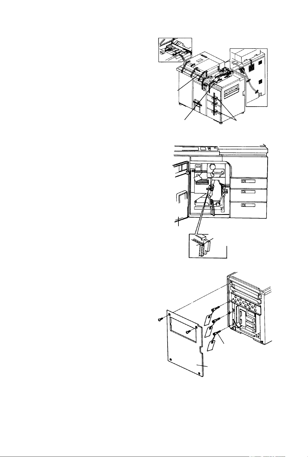
1.10.2 Installation procedure
1. Remove the exterior cover in the rear of the copy
tray (3 screws). Then, remove the two cover
brackets (2 screws each).
2. Install the key counter/printer connector bracket
with four M4x8 philips pan head screws and one
grounding screw (accessories).
3. Install the snap bushing (accessory) as shown.
4. Remove the copier rear right cover (2 screws).
5. Take the two connectors which are clamped
behind the key counter/printer connector bracket,
then feed them through the hole in the bottom of
the bracket as shown.
Exterior
cover
Cover
bracket
Snap bushing
Grounding
screw
Connector
bracket
Cover
bracket
1-43
Page 49

6. If an optional key counter is installed, install the
Printer Installation
1 July 1994
key counter receptacle with the two M3x8 philips
sunken head screws and key counter fixing plate
(accessories).
NOTE
The key counter must be one of the following:
- Hengstler (For the European version machine only)
- Hecon
- Veeder Root
Shorting
connector
Key
counter
receptacle
Key counter
fixing plate
7. Remove the shorting connector, then connect the
connectors from the key counter and copier.
8. Install the two wire clamps (accessories) and
clamp the harness as shown.
9. If the optional printer connector unit is not
installed, install the printer connector hole blind
cover with the two M3x6 philips plated screws (all
are accessories).
10. If the optional printer connector unit is
installed, install it with the grounding screw and
M4x8 philips plated screw (accessories).
11. Connect the connector of the harness form the
copier to the PCB on the printer connector unit.
12. Install the 4 nylon studs, then the printer interface
board. Connect the connector of the harness from
the printer connector unit to the interface board.
13. Install the printer harness with the two connector
joint studs.
NOTE
The printer interface board (P/N A112 5060), printer
harness (P/N A531 5420), 2 connector joint studs
(2 x P/N 1102 4039), and 4 nylon studs (4 x P/N
1105 0193), which are copier accessories, are
required for the printer connector unit installation.
Connector
joint studs
Grounding
screw
Wire clamp
Connector
[E]
Optional printer
connector unit
Blind cover
Printer interface
board
Grounding
screw
Nylon
studs
Wire
clamp
Printer
harness
Blind cover
Fixing
plate
14. Connect the other end of the printer harness to the
connector on the printer interface board.
15. Fix the grounding wire with the grounding screw
(accessory). Then, install the wire clamp
(accessory) then clamp the printer harness with
the clamp as shown.
16. 1If an optional key counter is not installed, install
the key counter hole blind cover with the two M3x8
philips sunken head screws and key counter fixing
plate (accessories).
1-44
Page 50

17. Install the key counter/printer connector bracket
1 July 1994
Printer Installation
cover [A] with the grounding screw [B] and the 4
M4x8 philips plated screws (accessories).
NOTE
If the optional printer connector is installed, a printer
with a standard RS232C interface is required. Use
a printer with the following functions:
Mode: Asynchronous
Data format: Start/Stop/Data: 1 bit each
Data bit length: 8 bits
Parity permission: With
Parity setting: Even parity
Baud rate setting: 1,200 bps
Connector: 25 pins, D-connector
Bracket
cover
Grounding
screw
1-45
Page 51

SECTION 2
REPLACEMENT AND ADJUSTMENT
Page 52

2. REPLACEMENT AND ADJUSTMENT
1 July 1994
Paper Feed
2.1 Paper Feed
2.1.1 Replacing the feed, reverse and pick-up rollers
PM cycle: Replace every 400K
NOTE
One set of the feed, reverse and pick-up rollers can
feed up to approximately 150,000 sheets of paper.
If the paper trays are not used evenly, replace the
rollers that are worn more with the rollers that are
worn less. Do this before any rollers wear out.
1. Press the tray down keys for all paper trays.
2. Turn off the main switch.
3. Pull out and remove the 1st tray (2 screws).
CAUTION
Note that the unit fixing screws are the stepped
screw on the right side and the plated screw on
the left side.
4. Pull out the 2nd and 3rd trays.
Stepped screw
Plated screw
5. Remove stop rings from rollers in the 1st, 2nd, and
3rd feed station.
6. Slide and remove rollers and replace rollers.
CAUTION
• Do not touch the new roller surfaces with
bare hands.
• Install the feed roller in the correct direction.
Paper feed roller
Pick-up roller
Reverse roller
2-1
Page 53

2.1.2 Replacing parts in the paper feed unit
Paper Feed
1 July 1994
Replace parts in the paper feed unit when:
• Electric parts are changed (paper feed motor,
various sensors and pick-up solenoid).
• The grip roller is replaced.
Removing paper feed unit
1. Remove the inner cover(s) from the vertical
transport unit.
2. Remove the paper tray from the paper feed station
as it is required to remove the feed unit.
3. Disconnect and put the paper feed connector to
the far side.
4. Loosen the slot head fixing shaft and pull it about
10 mm in the direction of the arrow.
Remove for the
1st tray
Remove for the
2nd or 3rd tray
1st tray
2nd tray
3rd tray
Paper feed connector
5. When you need to remove the feed unit at the third
feed station, remove the oil pump unit bracket (2
screws).
(-) fixing shaft
Fitting screw
Oil pump unit bracket
Oil tube
2-2
Page 54

6. Remove the screws from the paper feed unit fixing
1 July 1994
Paper Feed
bracket.
7. Hold the far side of the unit to move it to the right
and push the front to the far side to remove the
unit.
Checking the unit
Bracket
fixing
screw
Bracket fixing screw
1. Remove the paper tray.
2. Loosen and pull the (slot head) fixing shaft without
removing the two screws from the paper feed unit
fixing bracket.
3. The far side of the unit can be opened and closed
using the front as a fulcrum.
Replacing the torque limiter
1. Remove the paper feed unit.
2. To pull out the reverse roller, remove the stop ring.
3. Remove the reverse roller pressure arm stopper
(one screw).
4. To replace the torque limiter, lower the reverse
roller pressure arm.
CAUTION
• Because the torque limit pressure is
properly adjusted, do not loosen the torque
limiter stopper screws.
• Never touch the reverse roller surface with
bare hands.
Breaker
fixing
screw
Reverse roller
pressure arm
Stopper
Stop ring
Reverse
roller
(Minus head) fixing shaft
[NG]
Stopper
Torque limiter
2-3
Page 55

Replacing the pick-up solenoid
Paper Feed
1 July 1994
1. Remove the paper feed unit.
2. Mark the position of the solenoid bracket.
3. Remove the two solenoid bracket fixing screws
(gold color).
4. Remove the pick-up solenoid from the bracket and
replace it.
CAUTION
• Pull out one side of the plunger spring pin
about 4 mm and put it in the pick-up roller
arm hole.
• The solenoid bracket should be in the
marked-off position. The pick-up roller rise
amount various with the position.
5. Remove the E-ring from both sides and replace
the grip roller.
6. Assemble in the reverse order.
NOTE
The golden screw (zinc plated) shows the location
adjusted at assembly during manufacture.
Therefore, pay attention to how the screw is set
originally before you start working. When the screw
is loosened, adjustment is required.
4 mm
Pick-up solenoid
Gold screw
Pick-up roller arm
Solenoid bracket
2-4
Page 56

2.1.3 Replacing parts in the paper trays
1 July 1994
Paper Feed
PM cycle: Lubricate the tray motor worm
gear every 800K
1. Pull out the tray.
2. Remove the front and rear knobs (2 screws each),
and the tray bottom plate (6 screws). You can
replace the anti-condensation heater and paper
size sensors.
3. Remove the front tray cover (4 screws). You can
replace the front tray drive wire.
4. Remove the paper tray from the rails (2 screws)
when:
• Replacing the rear tray drive wire
• Replacing the tray motor and DC drive board
• Lubricating the worm gear
Tray drive wire layout diagram
The numbers shows the assembly steps.
FRONT REAR
Knob
Tray bottom
plate
Front tray cover
2 turns
clockwise
(blue wire)
Secure the
tension pulley
2 turns counterclockwise (blue wire)
2.5 turns counterclockwise
2.5 turns
clockwise
Secure the tension
pulley
2-5
Page 57

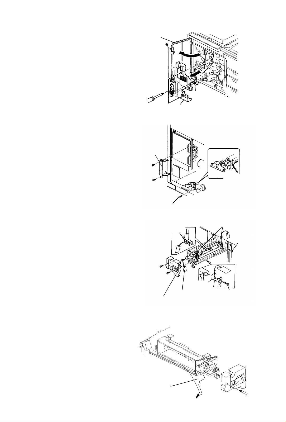
2.1.4 Replacing the registration sensor
Paper Feed
1 July 1994
1. Turn off the main switch. Open the front door, and
remove two screws to allow it to open further.
2. Remove the inner cover (2 screws and one
connector).
CAUTION
Do not pull the harness to the cooling fan in the
inner cover.
3. Turn the lever to release the development backup
roller of the OPC unit.
4. Remove the development unit fixing plate (one
screw), and slightly pull out the unit to disengage
the joint gear at the rear of the unit.
5. Turn the development knob to collect the
developer on the development sleeve.
CAUTION
Be sure to collect the developer, because the
developer may attach to the side plate of the
OPC unit, fraying or damaging the OPC belt.
Lever
Development knob
Fixing bracket
6. Slide out the development unit.
7. Remove the registration sensor (2 screws and one
clamp).
8. Remove the main body rear left cover (2 screws).
9. Remove the connector going to the registration
sensor from the back.
10. Reassemble in the reverse order.
CAUTION
Never touch the OPC belt.
2.1.5 Replacing the registration motor
1. Turn off the main switch.
2. Remove the rear left cover, then remove the
cleaning coil cooling fan.
3. Disconnect the connector from the registration
motor.
4. Loosen two screws of the universal joint attached
to the registration motor shaft.
5. Remove two screws fixing the registration motor.
6. Replace the registration motor and reassemble it
in the reverse order.
Clamp
Fixing screw
Registration motor
Fixing screw
Registration sensor
Connector for
registration motor
2-6
Page 58

2.1.6 Cleaning the paper dust collecting vessel
1 July 1994
Paper Feed
PM cycle: Clean every 1,200K
1. Pull out the 3rd tray.
2. Turn off the main switch. Open the front door, and
remove two screws to allow it to open further.
3. Remove the inner cover from the lower of the
vertical transport unit (3 screws).
4. Remove the OPC unit inner cover (2 screws and a
connector).
CAUTION
Do not pull the connector of the cooling fan in
the machine.
5. Turn the lever to release the development backup
roller of the OPC unit.
6. Remove the development unit fixing plate (one
screw), and slightly pull out the unit to disengage
the joint gear at the rear of the unit.
7. Turn the development knob to collect the
developer on the development sleeve.
CAUTION
Be sure to collect the developer because it may
stick to the side plate of the OPC unit, fraying or
damaging the OPC belt.
Paper dust
collecting vessel
Fixing screw
8. Slide out the development unit and remove the unit
from the rails.
9. Remove the vessel fixing screw from the front, and
remove the paper dust collecting vessel.
10. Clean inside of the vessel using a dry cloth, and
reassemble in the reverse order.
2-7
Page 59

2.1.7 Removing the vertical transport unit
Paper Feed
1 July 1994
You will have to remove the vertical transport unit when:
• Replacing the drive system
• Replacing each roller
WARNING
• Due to the weight, two operators are required.
• Be sure to pull out the power cord during work.
1. Pull out all paper trays.
2. Turn off the main switch.
3. Open the upper right door.
4. Open the front door.
5. Remove all inner covers: fusing, vertical transport
upper and vertical transport lower.
6. Remove two screws each to remove all paper
trays.
CAUTION
Vertical transport
upper inner cover
Plated screw
Fusing
inner
cover
Vertical transport
lower inner cover
Stepped screw
Tray fixing screws are stepped screws on the
right side and plated screws on the left side.
Take care during reinstallation.
7. Remove the upper and lower door catch magnets
with their brackets.
Door catch
magnet, upper
bracket
Door catch
magnet, lower
bracket
2-8
Page 60

8. Remove the horizontal transport unit inner cover.
1 July 1994
Paper Feed
9. Disconnect the front door switch harness
connectors.
CAUTION
Terminals on both sides are blue and the two
center terminals are yellows. Re-install them
correctly.
10. Disconnect the connector from the front door
sensor.
11. Mark off the position of the front door switch
bracket.
12. Remove the front door switch bracket (2 screws).
Front door
sensor
Horizontal
transport inner
cover
Front door switch
13. Remove the fusing unit fixing stepped screw to
remove the unit.
14. Remove the transport unit inner cover.
15. Remove the oil receiver (2 screws).
16. Remove the oil pump unit bracket (2 screws) and
the tube on the oil tank side.
Fixing
stepped
screw
Oil receiver
Transport unit inner
cover
Oil pump unit bracket
Oil tube
2-9
Page 61

17. Remove the male and female connectors for all
Paper Feed
1 July 1994
paper feed units.
18. Remove the three cord clamp screws.
19. Remove the grounding screw from the ground wire
of the connector to the transport unit.
20. Remove the male and female connectors for the
transport unit from the stay.
21. Release the transport unit to the right.
22. Hang the dismounting and mounting arm of the
transport unit on the pin.
23. Remove the fixing screws from the transport unit to
remove the unit.
CAUTION
Connector for
transport unit
Connector for paper
feed unit
Grounding screw
Cord clamp screw
Stay
Carefully pull out the units so that the transfer
and separation corona unit casing does not
touch the rollers or pressure springs of the
vertical transport unit.
24. Turn the lever to release the development backup
roller of the OPC unit.
25. Remove the development unit fixing plate (one
screw), and slightly pull out the unit to disengage
the joint gear at the rear of the unit.
26. Turn the development knob to collect the
developer on the development sleeve.
CAUTION
Be sure to collect the developer because it may
stick to the side plate of the unit, fray or damage
the OPC belt.
Transport unit
Pin
Dismounting and
mounting arm
Stay fixing screw
Stay fixing screw
27. Slide out the development unit and remove the unit
from the rails.
28. Remove five M5 screws fixing the vertical transport
stay.
2-10
Page 62

29. From the back of the machine, remove the
1 July 1994
Paper Feed
transformer then remove the three M5 screws
holding the vertical transport unit.
30. Disconnect the connectors of the harnesses from
the registration motor and registration sensor.
31. Disconnect the connector to paper feed motors in
all paper trays.
32. From the front, pull the vertical transport unit.
CAUTION
The unit is heavy so you will need a helper to
lift it away.
33. Reinstall the unit in the reverse order.
CAUTION
• Fix the front door switch in the marked-off
position.
• Remove the pulley after the tension pulley
bracket is marked off.
• Do not loosen the two bracket fixing screws
(golden screws) on the front side at the
same time when the registration roller or
like is replaced. If they are removed,
clearance with the OPC unit changes and
transport trouble or skew in registration
may occur.
• Tubes leading to the oil tank should not
sink below the oil level.
M5 screw
Connector for
paper feed
motor
Registration motor
Connectors
Timing belt layout diagram
Paper feed
motor (No. 1)
Vertical
transport
roller
Grip roller drive
Pinch roller
Bracket fixing screw
Tension pulley bracket
Joint gear
Registration
Paper dust
collecting roller
Registration roller
Paper
dust
collecting
roller
Registration knob
Golden screw
2-11
Page 63

Belt tension standard
Paper Feed
1 July 1994
3 mm deflection at 140 ± 90 g pressure.
2.1.8 Adjusting the side-to-side registration
100 mm
140 ± 90 g
3 mm
Standard value: 0 ± 2 mm in the platen
cover mode.
1. Set paper in the paper tray to be checked.
CAUTION
Be sure to set the paper side guides of the paper
tray securely.
2. Set the test chart on the exposure glass correctly.
3. Make a copy and measure the difference of the
side-to-side registration between the original and
copy.
4. If the value does not match the standard value
then the following steps should be taken:
1) Pull out the paper tray and remove the
tray front cover.
2) Loosen the lock nut and turn the tray
stopper to change the paper tray position
when set.
5. Make more than 10 continuous copies to check the
variation.
6. Be sure that all copies are within the standard
value. If problems still occur, repeat step 3 to 5.
CAUTION
Lock nut
Tray stopper
• An adjusting mechanism for the
side-to-side registration is provided for
each tray.
• Because the side-to-side registration
adjustment mechanism is also provided on
the original side (ADF and SADF), make
adjustments for each tray on the basis of
the platen cover mode.
2-12
Page 64

2.1.9 Adjusting the leading edge registration
1 July 1994
Paper Feed
Standard value: 0 ±2 mm in the platen
cover mode.
1. Set paper in the paper tray.
CAUTION
Be sure to set the paper side guides of the paper
tray securely.
2. Set the test chart on the exposure glass correctly.
3. Make a copy and measure the difference between the leading edge registration of the origi-
nal and the copy.
4. If the value does not match the standard, access service tool [5-02] and press the Registra-
tion key.
5. Change the value on the screen.
6. Make more than 10 continuous copies to check the variation.
7. Be sure that all copies are within the standard value. If problems still occur, repeat step 3 to
6.
2-13
Page 65

2.2 Optics
Optics
1 July 1994
2.2.1 Replacing the xenon lamp
PM cycle: Replace every 1,000K or when:
[(set value) + (shifted value)]
of the flash voltage step (Service tool [4-01]) exceeds 28.
CAUTION
If the cooling air flow to the xenon lamp and
flash power supply unit becomes low, the flash
voltage step will exceed 28 earlier than normal.
Be sure to do the following PM.
PM: Every 200K clean the filters for the
rear cooling fan, flash blower, exposure
cooling fan, flash power cooling fan
inside the left cover, and the flash power
inside blower on the rear left cover.
WARNING
After you turn off the power, wait at least 1 minute
for discharge before you start working.
1. Turn off the main switch.
2. Remove the left cover (2 screws).
3. Disconnect the two connectors to the exposure
cooling unit.
4. Remove the exposure cooling unit (4 screws).
5. Remove the xenon lamp connector (2 screws).
6. Remove the xenon lamp unit (2 screws).
Exposure cooling unit
Connector
2-14
Page 66

WARNING
1 July 1994
Optics
• To avoid wiring problems of high voltage parts,
never disassemble the connector.
• Working near the lamp is dangerous. Never
work near the lamp without turning off the main
switch and waiting at least 1 minute for
discharge.
• Take care and check the position of the lamp
harness. (See illustration below.)
[OK]
Lamp harness
Xenon lamp
connector
Connector
fitting screw
Xenon lamp unit
Flash safety switch
Unit fitting screw
[NG]
7. Remove the xenon lamp upper cover (2 screws).
8. Remove the thermofuse.
9. Remove the roof reflector (2 screws).
10. Remove lamp cooling guide seal.
11. Remove the lamp clamps from the front and rear
(one screw each).
12. Replace the lamp and reassemble in reverse order.
13. When the machine is in the stand-by condition,
access service tool [4-03]. Using the PC-1 chart
check the AID reference voltage. Perform setting A
if the value is not correct.
Xenon lamp upper cover
Thermofuse
Roof reflector
Cooling guide seal
Lamp clamp
Xenon lamp
2-15
Page 67

CAUTION
Optics
1 July 1994
• To avoid xenon lamp damage, firmly fit the
xenon lamp connectors to the sockets.
Push each connector end with your fingers
as shown. Then tighten two screws.
• When reinstalling the xenon lamp in the
unit, position the lamp exactly as shown. If
the position is not correct, the life time of
the lamp might be reduced. Insufficient
light intensity will increase the lamp voltage
rapidly due to the process control.
Xenon
lamp
connector
• If the lamp positioning tool (P/N-A0289330)
is available, the lamp installation becomes
much easier. Fix the tool with the two
screws and install the xenon lamp while
pushing the lamp against the tool (see the
illustration to the right). At that time, be
sure that both the right and left edges of the
lamp ("a" in the illustration) are the same
length.
Same length at
the right and
left edges.
13.5 mm
a
Lamp positioning tool
a
2-16
Page 68

2.2.2 Replacing the exposure glass
PM cycle: Clean it and check the
resistance at every visit. Wipe with silicon
oil to prevent original misfeeds caused by
static electricity.
WARNING
Working near the xenon lamp is dangerous after
removing the exposure glass. Never work near
the lamp without turning off the main switch and
waiting at least 1 minute for discharge.
1. Turn off the main switch.
2. Open the ADF unit.
3. Remove the front upper cover (2 screws).
4. Open the copy tray and remove the SADF
transport plate (one stepped screw on the rear and
one plated screw on the front).
5. Loosen two screws of the back upper cover.
6. Remove the exposure glass. Clean it if necessary.
7. Check the resistance of the glass upper surface
using the beckman multimeter. Replace the
exposure glass if necessary.
SADF transport plate
Front upper cover
Exposure glass surface resistance
standard: 55 KΩ or less.
8. When the machine is in the stand-by condition,
access service tool [4-03]. Using the PC-1 chart,
check the AID reference voltage. Perform setting A
if the value is not correct.
2.2.3 Replacing the mirror/lens motor
PM cycle: Lubrticate the motor worm
gear every 1,200K
1. Remove the exposure glass.
2. Loosen two screws (1) to remove the opposite
reflector. Clean the reflector as required.
3. Remove four screws (2) to remove the front
reflector. Also, remove the rear reflector.
CAUTION
Be careful not to scratch the lamp reflector
when removing the front and rear reflectors.
After removing screws, pull out the reflector
with the left side first.
Back shield cover
1st mirror
shield unit
Lamp reflector
Front
shield
cover
Opposite
reflector
4. Remove one screw (3) to remove the front shield
cover.
5. Remove one screw (4) to remove the back shield
cover.
6. Remove 8 fixing screws (5) to remove the 1st
mirror shield unit. Remove the unit upwards while
raising the inside plate.
Front reflector
2-17
Page 69

CAUTION
Optics
1 July 1994
The shaft should not come out of the shield unit.
7. To remove the fusing unit, pull out the unit and
remove one stepped screw.
8. Peel off three sheets of shielding mylar for the
mirror/lens motor fixing screws.
9. Remove the connectors for the mirror/lens motor
and mirror/lens home position sensor.
Connector for
magnification
home position
sensor
Connector for
mirror/lens
motor
Shielding mylar
Two stepped screws
M5 screw
10. Put a screwdriver through the blind to loosen the
mirror/lens motor fixing screws (2 stepped screws
and one M5 screw).
CAUTION
The 1st mirror unit drops if the screw is
completely removed. Before removing the
screws for the worm gear disengage, insert a
screwdriver in the mirror unit fixing hole to hold
the unit.
11. While holding the mirror/lens motor with one hand,
remove the three screws securing the motor.
CAUTION
Lubricate the worm gear of the mirror/lens
motor with Mobil Temp. 78 every 1200 K. You
do not have to remove the motor at that time.
12. Replace the motor and reinstall it in the reverse
order.
CAUTION
• Check and be sure that the worm gear of
the mirror/lens motor is correctly engaged.
• When power is turned ON, the mirror/lens
motor starts and stops when the 1st mirror
unit activates the magnification home
position sensor.
Mirror unit
fixing hole
1st mirror unit
2-18
Page 70

2.2.4 Replacing the first mirror
1 July 1994
Optics
PM cycle: Clean the 1st mirror every
200K
NOTE
To clean the 1st mirror, it does not need to be
removed. Just remove the exposure glass to clean.
1. Remove the 2nd mirror according to the
instructions described below.
2. Remove the two set screws from the underside of
the 1st mirror.
3. Hold the underside of the mirror and slide it down
to remove it.
CAUTION
1st mirror
Take care not to drop the mirror.
4. Reinstall the mirror after cleaning.
5. When the machine is in the stand-by condition,
access service tool [4-03]. Using the PC-1 chart,
check the AID reference voltage. Perform setting A
if the value is not correct.
2.2.5 Replacing and cleaning the 2nd mirror
PM cycle: Clean as necessary at PM
1. Turn off the main switch.
2. Remove the left cover (2 screws).
3. Remove two set screws from the 2nd mirror.
CAUTION
Hold the 2nd mirror with one hand so it does not
fall.
4. Move the 2nd mirror to the left (outside) to avoid
the DC power source, pulling it out then down.
5. After cleaning, reinstall it in the reverse order.
CAUTION
Set screw
Set screw
Locating pin
Set the locating pin first to install the 2nd mirror
unit. (See illustration.)
6. When the machine is in the stand-by condition,
access service tool [4-03]. Using the PC-1 chart,
check the AID reference voltage. Perform setting A
if the value is not correct.
2nd mirror
2-19
Page 71

2.2.6 Replacing parts in the shield unit
Optics
1 July 1994
Removing the shield unit
1. Turn off the main switch.
2. Remove the left cover (2 screws).
3. Open the front door and remove two screws to
allow it to open further.
4. Remove the inner cover (2 screws and one
connector).
5. Remove the four connectors of the DC power
source.
6. Remove four fixing screws and loosen the lower
side screws to remove the DC power source.
7. Remove the two screws fixing the shield unit from
the left.
DC power
source
Shield unit
fixing screw
8. Disconnect the connector for the shield unit from
the front.
9. Remove the shield unit fixing screws (M6).
10. Pull out the shield unit to the left along the rail.
CAUTION
• Hold the front and back side plates, not the
shield screen to pull out the shield unit.
• Press the upper stays of the shield unit
against the far side of the front and rear
rails, and fix the shield unit.
Shield unit
Rail
Shield unit
Shield unit
fixing screw
Stay
Connector for
shield unit
2-20
Page 72

Replacing the shield motor
1 July 1994
Optics
1. Remove the shield unit.
2. Remove the shield motor cover (one screw).
3. Remove two fixing screws from the shield motor
and replace the motor.
Replacing the shield screen
1. Remove the shield unit.
2. Remove the timing belt fixing screws, front and
back, from the shield screen unit to enable
replacement.
CAUTION
[FRONT SIDE]
Shield motor cover
Shield motor left and right
Timing belt fixing screw
Spring washer
Slider
[REAR SIDE]
Rail
• Do not lose the spring washer under the
fixing plate.
3. Remove one stepped screw and one pan head
screw to remove the back side of the timing belt
tension. Remove the belt.
4. Loosen one tension fixing screw to remove the
front side belt.
5. Remove E-rings from the shield roller and pull out
the roller.
6. Move the shield screen slider to the center along
the rail and remove it from the back side. Clean
the rail and slider with alcohol.
7. Replace the shield screen unit and re-install it in
the reverse order.
Adjusting belt tension
1. Loosen all tension fixing screws.
2. Tighten the screws when the tension spring works.
Shield screen
Shield roller
Stepped screw
Timing belt
2-21
Page 73

Adjusting the shield screen position
Optics
1 July 1994
1. Adjust belt tension.
2. Move the slider to the center.
3. Turn the shield motor shaft gear by hand to move
the slider. Let it slide until the front or back slider is
brought in contact with the stopper.
4. Bring the other slider in contact with the stopper
and turn the motor gear further by two teeth of the
belt gear.
5. Tighten the fixing screw.
6. Turn the motor gear by hand again and check that
the shield screen moves smoothly without rolling.
NOTE
• If you detect rolling, repeat this procedure.
Dirt, toner, etc., should not be on the rail.
• To check tension of the shield screen, fully
close the leading and trailing edge of screen,
and lightly press the center with your finger.
Tension is OK if the screen returns easily and
is not slackened when it is released.
7. The stays on the shield unit should fit to the main
body side rails first when the shield unit is
reinstalled.
Timing belt
fixing screw
Shield motor shaft
Slider
Slider
Stopper
2-22
Page 74

2.2.7 Replacing the flash power supply unit
1 July 1994
Optics
WARNING
Before you start working, turn off the main switch
and wait for at least one minute to allow for
discharge.
1. Turn off the main switch.
2. Remove the left cover (2 screws).
3. Disconnect the connector from the flash exhaust
unit and remove four screws to remove it.
4. Remove the connectors for the xenon lamp
(2 screws).
5. Disconnect the 2P connector to the trigger
transformer.
Trigger transformer
Red
2P connector White line
Black
Flash power
source line
(trigger)
Red wire (tape
indicates polarity)
Black line (tape
indicates polarity)
(+)
(-)
6. Remove three lines connected from the flash
power supply unit to xenon lamp connector
together with the terminal fixed with two screws
each.
7. Remove the rear left cover.
8. Disconnect two connectors (15P and 3P) from the
upper part of the flash power supply unit.
9. Remove the air blow guide (2 screws) from the
lower part of the flash power supply unit.
10. Remove the flash power supply unit.
Remove the upper two screws and only loosen the
lower two.
11. Replace the flash power supply unit and
reassemble in the reverse order.
CAUTION
• Be sure to wire the three flash power
source lines correctly, the white wire (from
the trigger transformer), red line and black
line from the top. If wired incorrectly, the
lamp may burn up.
• To avoid xenon lamp damage, firmly fit the
lamp connector to the socket. Push each
connector end with your fingers. Then,
tighten two screws.
Connector
Flash power
supply unit
2-23
Page 75

2.2.8 Checking the flash power supply output
Optics
1 July 1994
1. Remove the clear cover from the flash power
supply unit.
2. Connect the Beckman multimeter between J1(+)
and J2(-). (Range: 20V)
3. Access service tool [5-04], input/output test.
4. Select Lamp/Sol menu and press Charge key.
5. It is normal if the 1/1,000 value of the lamp output
can be read according to the combination of bits
[0][1][2][3][4] as follows:
* About 1.07V with [0] to [4] all OFF
* About 2.00V with [0] to [4] all ON (full power)
2.2.9 Adjusting the uneven illuminance
CAUTION
This adjustment is usually prohibited.
It seems difficult to return the illuminance to the
original setting if you change the position of the
front and rear reflectors.
CAUTION
Never work near the xenon lamp after the flash power
is charged. Be sure to discharge it using the
Discharge key ("Dis" key) in the service tool screen.
Hex socket screw
Reflector adjusting nut
Reflector adjustment shaft
Reflector adjustment bracket
1. Use graph paper of A3 size as the original.
2. Copy at the second level of the image density.
3. Check uneven illuminance and make adjustment
with front and rear reflectors.
CAUTION
At this time, set the whole density to the dark
part at the trailing edge of the copy image.
4. After the adjustment, access service tool [4-03]
and check the AID reference voltage using the
PC-1 chart. Perform setting A if the value is not
correct.
CAUTION
When you cannot set the V L target data in the
[4-01] screen due to too low value of the V L
measured data, light quantity to the pattern may
be too high. Therefore, adjust illuminance
again to lower the light quantity to the pattern.
Front reflector
Set the whole to
this density
Reflector
Reflector
adjusting
mechanism
Rear reflector
2-24
Page 76

2.2.10 Adjusting the magnification
1 July 1994
Optics
Standard value:
±0.5% or less at length and at width in
the full size mode.
±1.0% or less at length and at width in
any other magnification ratios.
1. Copy a scale as an original.
2. Measure copy dimensions, and calculate the error
in magnification.
3. Access service tool [5-02]. Press the Magnification
key, and adjust the magnification.
4. Repeat this procedure to set the standard value.
2-25
Page 77

2.3 OPC Unit
OPC Unit
1 July 1994
2.3.1 Replacing the OPC belt
PM cycle: Replace every 200K
1. Turn off the main switch.
2. Open the front door, then remove two screws to
allow it to open further.
3. Disconnect the connector from the fan and remove
the inner cover (2 screws).
4. Disconnect the charge corona connector.
5. Pull out the charge corona unit.
6. Release the cleaning backup roller by turning lever
(1).
7. Release the development backup roller by turning
lever (2).
8. Release the transport unit to the right side.
9. Turn the development knob and collect the
developer on the development sleeves.
CAUTION
• Be sure to collect the developer because it
may stick to the side plate of the OPC unit,
damaging the OPC belt.
• To turn the development knob, slightly pull
out the unit and disengage the joint gear at
the rear of the unit.
Charge corona
connector
Charge
corona unit
Development
knob
Lever (1)
Transport unit
Lever (2)
10. Remove the OPC unit stay by turning the knob.
11. Slide out the OPC unit.
12. Turn lever (3) to loosen the tension of OPC belt.
13. Insert two OPC mounting/dismounting tubes in the
bosses and pull out the OPC belt this way.
OPC unit
OPC unit stay
Knob
Lever (3)
OPC mounting/dismounting tube
2-26
Page 78

14. Set a new OPC belt.
1 July 1994
OPC Unit
CAUTION
• Set the OPC belt so the mark is on the far
side.
• Put far side of the OPC in the OPC sensor
and set it in the center.
• Never touch the OPC surface, and position
the OPC belt carefully to prevent bending it.
• Do not expose the OPC belt to daylight for
more than a few minutes. When not
installed, keep the OPC belt in its case and
store it in a cool, dark place. If copying is
done while the exterior covers are off and in
slight daylight, even after it is set in the
copier, the copy image becomes extremely
light.
• Never use alcohol or other chemicals to
clean the OPC.
15. Slowly turn lever (3) back to its original position
and put tension the OPC belt.
16. Press and set the OPC unit.
17. Fit the OPC unit stay.
18. Turn levers (1) and (2) to set the development and
cleaning backup rollers.
19. Shift the transport unit to the left.
20. Fit the charge corona unit and the connector.
21. Install the inner cover and doors in the reverse
order.
22. Turn on the main switch and wait for the machine
stand-by.
23. Access service tool [3-04] (or [4-04]) and perform
the OPC forming. Reset the supply yield counter
for the OPC to 0 at the same time.
24. Select service tool [5-06] and check the tracking
operation. If necessary, adjust the tracking amount
(see Adjusting the tracking amount section).
25. Select service tool [4-02] and check the VSG. If
the value is not between 2.5 and 4.5 volts or it is
locked, perform setting C.
Mark
Lever (3)
OPC sensor
Charge
corona unit
2-27
Lever (1)
Transport unit
Lever (2)
Page 79

2.3.2 Replacing parts in the OPC unit
OPC Unit
1 July 1994
PM cycle: Every 400K clean: The OPC
back cleaning pad, all rollers, OPC
sensor, and quenching lamp filter.
Every 800K: Lubricate the tracking
sliders, and check the timing belt tension.
1. Remove the OPC belt by following the procedure
on the preceding page. Keep the OPC belt in its
case.
2. Clean each part as follows:
Cleaning pad Wipe with a cloth damp with alcohol. Reverse
Drive and
driven rollers
OPC sensor Blower brush
Replacing the quenching lamp
if it becomes dirty.
Wipe with a dry cloth. Never use either,
toluene or another organic cleaning solvent.
PM cycle: Clean the lamp filter every
400K
1. Remove the OPC belt.
2. Pull down the two lamp connectors.
3. Remove two screws to remove the lamp fixing
bracket.
4. Remove three screws to remove the lamp filter.
5. Remove and replace the quenching lamp.
OPC belt
Packing case
Lamp fixing bracket
Quenching lamp
Lamp connector
Lamp filter
Removing the OPC unit
1. Remove the OPC belt.
2. From the back of the OPC unit, while holding down
the lock pawl with your fingers, pull out the OPC
unit.
3. Erect the unit on the floor with the far side down.
WARNING
• Do not hold the frame and stays inside the unit
when you pull out it. Their edges are very sharp.
• If the slide guides keep slid out, it is dangerous
during working. Set the release lever on the far
side of the rail parallel, and put slide guide on
the main body side.
CAUTION
To reinstall the OPC unit, bring the roller
bearing unit inside the slide guide to the front
end of the rail. If the roller baring unit is kept on
the far side, the roller bearings may drop when
the unit is inserted.
Lock pawl
Release lever
2-28
Page 80

Replacing the development backup roller
1 July 1994
OPC Unit
1. Remove the OPC unit.
2. Turn the lever to apply tension to the development
backup rollers.
3. While holding down the backup rollers with your
hand, set free the release hook.
Lever
Development
backup roller
4. Remove the roller unit.
5. Replace the rollers.
CAUTION
If the backup rollers are changed or the
arrangement of the three rollers are changed,
this may affect the PG (Photoconductor Gap).
Check copy image, and adjust the development
motor speed if necessary (see Development
unit section for the adjustment).
Release hook
Backup roller unit
2-29
Page 81

Replacing the sector sensor and tracking motor
OPC Unit
1 July 1994
Fixing bracket
1. Remove two screws to remove the tracking motor
fixing bracket.
2. Remove two screws to replace the motor and
remove one screw to replace the sector sensor.
Replacing the quenching lamp stabilizer
1. Remove three screws to remove the QL stabilizer.
Lubricating the tracking slider
PM cycle: Lubricate every 800K
1. Lubricate the moving parts (front and rear of the
OPC unit) using G-40M.
Tracking
motor
Sector sensor
QL stabilizer
Tracking slider
Replacing the OPC motor and timing belt
PM cycle: Check tension of the timing
belt every 800K
1. Remove two screws to remove the motor.
2. When the motor is removed, the drive belt can be
also replaced.
Belt tension standard
Adjust by moving the OPC motor.
2 mm deflection at 200 ± 50 g pressure.
2 mm
OPC motor
OPC sensor
Drive roller
Drive belt
Set screw
200 ± 50 g
2-30
Page 82

2.3.3 Cleaning the ground brush
1 July 1994
OPC Unit
PM cycle: Clean every 400K.
1. Pull out the OPC unit.
2. Wipe the ground brush at the front with a dry cloth.
3. Slightly pull out the development unit and turn the
development knob to collect the developer on the
sleeves.
4. Pull out the development unit to clean the ground
brush at the rear.
2.3.4 Replacing the slide guide
Front ground brush
1. Remove the OPC unit.
2. Remove the stepped screw holding the slide guide.
3. Replace the slide guide.
CAUTION
Replace the slide guides as a set of the main
body and OPC unit sides. If the fit is poor, the
roller bearings inside the rail may get out of
alignment when the unit is set.
Stepped screw
2-31
Page 83

2.3.5 Adjusting the tracking amount
OPC Unit
1 July 1994
1. Access service tool [5-06].
2. Turn OPC motor ON.
3. Tracking from the front side to back side will start
displaying the transfer time on the screen.
Tracking from the back to front then occurs.
4. If the transfer time is within the standard time, 60
sec. (120 sec. both ways), OK is displayed.
If it is longer than the standard time, or if
there is a significant difference in the timing
from one side to the other (more than 20
sec.), you will have to follow the adjustment
procedure below.
5. If the interval from the front side to the back side is
too long, tighten the nut.
6. If the interval from the back side to the front side is
too long, loosen the nut.
7. Check the tracking time again. Leave the service
tool if it becomes OK.
2.3.6 Checking the tracking motor operation
OPC belt
Tracking
adjusting nut
1. Access service tool [5-06].
2. Turn Tracking motor ON.
3. Read the measured and displayed tracking time.
4. The time is usually about 0.5 sec. If the time is 1
sec. or more, check the following items.
• Tracking motor damaged?
• Gears failing to mesh?
• Carrier sticking to worm gear?
• Slider lacks lubrication?
• Sector sensor defective?
2-32
Page 84

2.4 Charge Corona Unit, Eraser, and Potential Sensor
1 July 1994
Charge Corona Unit, Eraser, and Potential Sensor
2.4.1 Replacing the charge corona wires and wire cleaners
PM cycle: Clean every 200K and replace
every 400K.
1. Turn off the main switch. Open the front door, and
remove two screws to allow it to open further.
2. Remove the inner cover (2 screws and one
connector).
3. Disconnect the connector from the charge corona
unit, and pull out the unit.
4. Remove the motor cover from the charge corona
unit.
5. Remove four screws to remove the cleaner unit.
6. Remove the two flat head screws to remove the
wire cleaners.
7. Clean the grid wires, end blocks, and casing.
8. Clean or replace the charge corona wires, corona
wire cleaner, and grid wire cleaner.
CAUTION
• Every 200K use a cloth damped with water
to clean the casing. Use a dry cloth to clean
the corona wires.
• The corona wire joint should be in the end
block and the wire should be in the L
groove corner.
• To prevent breaking the corona wire, turn
the screw shaft by hand and fit the cleaner
bracket with the front end block. Then,
install the wire cleaners and cleaner unit.
• Pay attention to the fitting direction of the
wire cleaner.
Cleaner unit
Motor cover
Grid wire cleaner
Corona wire cleaner
Cleaning motor
Flat head screw
Cleaner bracket
Corona
wire cleaner
Screw shaft
Corona wire cleaner
End block
L groove
Cleaner bracket
9. Reassemble in the reverse order of disassembly.
10. Check the copy image. Loose the height fixing
screws and turn the cam to adjust the position of
the front side of the unit if there is difference in
density between the front and rear of the copy
image.
Height adjusting cam
2-33
Height fixing screw
Page 85

2.4.2 Cleaning the eraser and potential sensor
Charge Corona Unit, Eraser, and Potential Sensor
1 July 1994
PM cycle: Clean every 200K
1. Turn off the main switch. Open the front door, and
remove two screws to allow it to open further.
2. Remove the inner cover (2 screws and one
connector)
3. Disconnect a connector from the eraser blower.
4. Remove one screw to remove the eraser blower.
5. Pull out the eraser and wipe it off with a damp
cloth.
6. Pull the sensor connector out of the potential
control board.
7. Pull out the potential sensor and clean it.
CAUTION
Blow air to remove toner and dust from the
electrode. To prevent clogging or jamming, do
not use a rag.
8. Assemble in the reverse order of disassembly.
NOTE
Potential sensor
Clear by blowing air
The copy image density may change slightly after
the potential sensor is replaced because the read
potential value may differ slightly from the old
sensor. Check data in the [4-02] screen after
replacing it.
2.4.3 Checking the potential sensor
1. In the copy stand-by condition, measure the voltage between TP6 and TP1 (Ground) on the
interface board. If it is between 1.99 and 2.01 volts, the sensor B is normal. (If the sensor is
defective, it will be 7 to 9 volts or 0 volt.)
2. To turn on the sensor A, short connector CP2-2 and CP2-3 (Ground) on the potential control
board. Otherwise, select "Lamp/Sol" in service tool [5-04] and press "VD Sensor" key. Fol-
low the same procedure as the above to check the sensor A.
2-34
Page 86

2.5 Transfer/Separation Corona Unit and Transport Unit
1 July 1994
Transfer/Separation Corona Unit and Transport Unit
2.5.1 Replacing the transfer and separation corona wires
PM cycle: Clean every 200K and replace
the corona wires every 400K.
Replace the receptacle and its two
springs on the corona unit every 1,200K.
1. Turn off the main switch and open the front door.
2. Remove the screws to remove the knob (C) of the
transport unit.
3. Pull out the T/S corona unit.
4. Pull out the covers at the front and rear, and
remove the separation guides. Clean every 600K.
5. Replace or clean the corona wires with a cloth
damp with water. Also, clean the end blocks and
casing.
6. Put anti-vibration rings in new wires and assemble
in the reverse order.
7. Replace the receptacle and its two springs on the
corona unit as required.
CAUTION
• Every 200K use a cloth damped with water
to clean the casing. Use a dry cloth to clean
the corona wires.
• The corona wire has no directional
requirements but the anti-vibration ring
should be in the space of the end block.
• The wire should be put in the L groove
corner of the end block.
Anti-vibration
ring
Spring
Separation guide
Receptacle
Front end
block cover
2-35
Page 87

2.5.2 Replacing parts in the transport unit
Transfer/Separation Corona Unit and Transport Unit
1 July 1994
Removing the transport unit
1. Pull out first paper tray.
2. Turn off the main switch, and open the front and
upper right doors.
3. Remove each inner cover from the fusing, upper
vertical transport, and transport units.
4. Pull out the connector of the transport unit.
5. Shift the transport unit to the right.
6. Loosen the fixing screw of the mounting and
dismounting arm, and hook the arm on the pin.
7. Remove one screw fixing the transport unit.
8. Draw the fusing unit and pull out the transport unit.
CAUTION
Carefully pull out the unit so that the casing of
the T/S corona unit is not brought in contact
with rollers and pressure springs of the vertical
transport unit.
Removing the vacuum unit
Drive joint
Fixing screw
Unit fixing screw
Connector
Pin
Mounting and
dismounting arm
PM cycle: Clean the fusing entrance
guide plate every 200K
1. Remove three screws (two on the front and one on
the far side) fixing the vacuum unit.
2. Slide the vacuum unit to the front to disengage the
drive joint.
3. Disconnect the connector from the separation
sensor.
4. Remove the unit and clean the fusing entrance
guide plate on the main body side. If the unit is not
removed every 200K, remove the fusing unit and
clean it from the top.
Transport belt
Fixing screw
Connector for
separation
sensor
2-36
Page 88

Replacing the transport belt and roller
1 July 1994
Transfer/Separation Corona Unit and Transport Unit
PM cycle: Clean every 600K
1. Pull the joint side of the transport roller and slide
the roller.
2. Move the transport roller to the underside of the
guide plate.
3. Replace the transport belts and assemble them in
the reverse order.
NOTE
Drive the transport roller by hand and check that the
transport belts are not put aside and rotate
smoothly.
Transport belt
Transport roller
Joint
Replacing the separation sensor
1. Remove the transport belts.
2. Remove four screws to divide the transport guide
plate into upper and lower parts.
3. Replace the separation sensor and assemble in
the reverse order.
Replacing the transfer and separation power pack
1. Remove the transport unit and place it up side
down. Remove three screws to remove the power
pack inner cover.
2. Pull out the power pack connector.
3. Disconnect the ground wire.
4. Remove the cord clamp and disconnect the cord
terminals.
5. Remove three screws to remove the power pack
and assemble in the reverse order.
Separation sensor
Power pack inner cover
Ground wire
Power pack
2-37
Page 89

2.5.3 Replacing the transfer entrance guide mylar
Transfer/Separation Corona Unit and Transport Unit
1 July 1994
PM cycle: Replace every 800K
1. Measure the length between the leading edge of
the mylar and the corona unit casing as shown.
2. Replace the mylar and its bracket with new ones
(2 pan head screws).
3. Loosen the 2 flat head screws (mylar position
fixing screws) and turn the adjusting knobs so that
the length between the mylar and corona unit
casing becomes the same as the old one’s.
NOTE
The clearance between the mylar and OPC belt is
1.45 ± 0.1 mm when fitted to the main body. Note
that transport trouble, irregular transfer, etc. may
occur when the value changes.
4. If the whole T/S corona unit is replaced, adjust the
mylar position as follows:
(1) Loosen the 2 flat head screws (mylar
position fixing screws) and install the T/S
corona unit in the machine.
(2) Using the tracking motor ON key on the
service tool [5-06], move down the front
side of the tracking rollers. The OPC
surface comes close to the leading edge of
the transfer entrance guide mylar.
(3) Turn the front side of the adjusting knob
so that the leading edge of the mylar is just
in contact with the OPC surface.
(4) Remove the T/S corona unit.
OPC belt
Adjusting knob
Measuring
Front adjusting
knob
(5) Turn the rear side of the adjusting knob
to level the front and rear of the leading
edge of the mylar. To do so, refer to the
edge of the corona unit casing as shown.
(6) Turn the front and rear adjusting knobs
28 notches (2 turns) and 3 notches counter
clockwise. Then, turn them 2 notches
clockwise and tighten the mylar position
fixing screws. (One notch turn of the knob
moves the mylar 0.05 mm.)
NOTE
If the mylar position is not proper, an insufficient
image transfer may occur on the leading edge of
copies (blank or faint image).
Rear adjusting knob
2-38
Page 90

2.6 Cleaning Unit
1 July 1994
Cleaning Unit
CAUTION
When you pull out the cleaning unit and turn the
cleaning knob, toner will fall from the toner exit
pipe of the unit. When you do this, place a sheet
under the toner exit pipe to prevent the OPC unit
from becoming dirty by toner.
2.6.1 Replacing the cleaning carrier
PM cycle: Replace every 400K
Cleaning unit
fixing screw
Cleaning knob
1. Turn off the main switch. Open the front door, and
remove 2 screws to allow it to open further.
2. Remove the inner cover (2 screws and one
connector).
3. Remove the cleaning unit fixing screw.
4. Turn the lever to release the cleaning backup roller
of the OPC unit.
5. Grasp the knob of the cleaning unit and pull it out.
6. Put the cleaning carrier collecting vessel on the
bottom of the unit. Set its lever to the carrier
collecting position to erect the rubber blade.
Cleaning carrier
collecting vessel
lever
7. Loosen the main pole adjusting plate fixing screw
(gold screw) and move the main pole adjusting
plate to the carrier collecting side.
CAUTION
Remember the position of the main pole
adjusting plate. This position is sometimes
different from one machine to another.
8. Turn the cleaning knob toward the arrow and
collect the cleaning carrier.
9. Remove the cleaning filter cover (4 screws), and
clean the inside from the above using the carrier
collecting magnet.
10. Return the main pole adjusting plate to its original
position. Tighten the gold screw.
Cleaning roller gear
Main pole
adjusting plate
Carrier collecting direction
2-39
Original
position
Main pole
position decal
Gold screw
Page 91

11. Put one bag of cleaning carrier in the right side
Cleaning Unit
1 July 1994
spread evenly.
CAUTION
Never put in cleaning carrier on the left side
(scavenging roller side).
12. Turn the cleaning knob to circulate the cleaning
carrier evenly on the cleaning roller.
NOTE
The cleaning unit has no agitation mechanism like as the
development unit.
13. Assemble in the reverse order.
14. Turn on the main switch and wait for the copy
stand-by.
15. Access service tool [3-04] and perform the
cleaning carrier forming. At the same time, reset
the supply yield counter for the cleaning carrier to
0.
2.6.2 Replacing the air filters
Cleaning filter cover
Cleaning knob
Cleaning
carrier
PM cycle: Rotate between left and right
every 200K. Replace every 400K.
1. Slide out the cleaning unit.
2. Remove the filter cases (2 screws).
3. Rotate the filter right to left, or replace them.
CAUTION
The filters have a setting direction. Be sure that
the side with a red line on the edge is facing the
inside of the unit.
2.6.3 Replacing the scavenging blade
PM cycle: Inspect every 200K. Replace
every 600K.
1. Slide out the cleaning unit, and remove cleaning
filter cover.
2. Remove the blade bracket (3 screws).
3. To replace the blade, remove the blade support
plate (4 screws).
NOTE
Projection
Hole
Scavenging blade
Blade bracket
Blade
support plate
Filter case
Air filter
• Align the holes of the scavenging blade with
the projections of the blade support plate.
• If the blade is dirty, clean it with alcohol.
2-40
Page 92

2.6.4 Replacing the scavenging roller
1 July 1994
Cleaning Unit
PM cycle: Inspect every 200K. Replace
every 600K.
1. Remove the unit fixing screw and slide out the
cleaning unit.
2. Remove the filter cover, and remove the cleaning
carrier.
3. Remove the cleaning knob with the E-ring.
4. Remove the E-ring and drive gear from the
scavenging roller shaft.
5. Remove the other E-ring from the shaft, then take
off the two screws to remove the bearing case.
Pull out the scavenging roller to replace it if
required.
NOTE
If the scavenging roller is dirty, clean it.
6. Wipe off the internal air guide mylar with a dry
cloth.
7. Assemble in the reverse order.
NOTE
• Do not remove the doctor blade. If it is
removed, adjust the doctor gap to 2 ± 0.15 mm
after the cleaning carrier is cleaned from
between the doctor blade and the cleaning
roller, after the unit is divided into two parts.
(See Replacing the cleaning roller section)
• Clean the area near the scavenging roller
bearing thoroughly to remove any remaining
cleaning carrier.
Scavenging roller
Bearing case
Doctor blade
Cleaning knob
Drive gear
Cleaning roller
2-41
Page 93

2.6.5 Replacing the PCC wire
Cleaning Unit
1 July 1994
PM cycle: Clean every 200K. Replace
every 400K.
1. Remove the PCC corona unit fixing screw on the
cleaning unit and pull out the unit.
2. Remove the end block covers (front and rear).
3. Clean the PCC wire and casing, or replace the
PCC wire if required.
4. Assemble in the reverse order.
CAUTION
• Every 200K use a cloth damped with water
to clean the casing. Use a dry cloth to clean
the corona wire.
• Check and be sure that the wire on the far
side is in the V-groove of the end block.
• Height adjustment is possible on this side
but is normally not done. Adjust to height
of 10 ±1 mm if the end block is replaced.
2.6.6 Removing the cleaning unit
Rear end block cover
PCC wire
Front end block cover
1. Remove the cleaning unit fixing screw, and slide
out the unit.
2. To pull the cleaning unit out of slide guide, pull the
cleaning unit while holding down the lock pawl.
CAUTION
• Because the slide guides have sharp edges,
keep them in the main body.
• Lay paper in place where the cleaning unit
is put. Be sure there is no metal debris
present that can cause damage. Metal
screws, paper clips, etc. attracted by the
cleaning roller can scratch the roller and
blade.
• Because the cleaning unit has no horizontal
agitating roller, do not tilt the unit when the
cleaning carrier is in the unit.
• When the cleaning carrier is in the cleaning
unit, do not turn the unit up side down.
Slide guide
Lock pawl
2-42
Page 94

2.6.7 Replacing the cleaning roller
1 July 1994
Cleaning Unit
1. Remove the cleaning carrier, then remove the unit.
2. Remove three screws to move the rear magnet
holder bracket together with the V-seal at the back
of the unit.
3. Remove the C-ring, drive gear and V-seal. If too
tight, this can be done after dividing the unit casing.
V-seal
Drive gear
Rear magnet
holder bracket
V-seal
4. Remove the front magnet holder bracket (4
screws) from the front of the unit, together with the
main pole adjusting plate.
CAUTION
• Do not loosen the main pole adjusting plate
fixing screw (gold screw). If it needs to be
loosened, remember the original position of
the adjusting plate.
5. Remove the C-ring and the relay gear. It can be
done after dividing the unit casing if too tight.
Relay gear
Front magnet
holder bracket
Main pole
adjusting plate
2-43
Page 95

6. Tilt the unit 90
Cleaning Unit
1 July 1994
the top.
o
so that the cleaning roller moves to
7. Disconnect the PCC power pack connector.
8. Remove the drawing rail (2 screw).
9. Divide the cleaning unit into two parts (4 screws).
10. Remove the front and rear bearings and bearing
cases (one C-ring each front and rear).
11. Remove the cleaning roller, and replace it.
12. Reassemble in the reverse order.
CAUTION
Drawing rail
Connecting screw
PCC power
pack connector
Cleaning roller
Shaft
• Use a dry cloth to wipe and clean the inside.
• Confirm that the bias terminal board is in
close contact with the bearing case.
• Because the cleaning roller shaft moves, fit
the rear magnet holder bracket after the
front magnet holder bracket is fitted.
• Take care that the two V-seals have the
different setting direction as shown.
• Use three M4 x 14 screws to fit the rear
magnet holder bracket. Gradually, tighten
the three screws so that the inside V-seal
just fits the cleaning roller shaft.
2.6.8 Replacing the slide guide
1. Remove the cleaning unit from the slide guides.
2. Remove the stepped screw from the front side and
replace the slide guide on the main body side.
3. Replace the guides as a pair on the main body
side, and on the cleaning unit side in the same
way as the slide guide of the OPC unit. This is
because the roller bearing inside the rail may
come out of place when the unit is set.
M4 x 14 (3)
V-seal
2-44
Page 96

2.6.9 Replacing the PCC power pack
1 July 1994
Cleaning Unit
1. Pull out the cleaning unit.
2. Take off the two power pack fitting screws.
3. Remove ground wire fixing screw, and disconnect
the connector and harness.
2.6.10 Checking the cleaning and scavenging bias
1. Pull out the cleaning unit.
2. Remove the varistor.
NOTE
PCC power pack
Power pack fitting screw
Although the cleaning power pack is a constant
current type, the varistor makes the bias voltage to
the cleaning roller constant. Removing the varistor
allows for adjusting the amperage.
3. Remove the rear left cover and set an ammeter to
the cleaning power pack as shown.
NOTE
To measure the cleaning roller side, disconnect the
wire from the "CL" terminal (indicated on the power
pack). Then, set an ammeter between the wire
connector and terminal. To measure the
scavenging roller side, use the "S" terminal.
WARNING
When the main switch is ON, never touch
anything inside the rear left cover to avoid
possible injuries.
4. Turn on the main switch. After the copier enters
the stand-by condition, access the service tools.
5. Select [5-04] "I/O Test". Press the "Motor" key,
then press the "Main" and "OPC" keys. Press the
"Lamp/Sol" key, then press the "QL" key.
NOTE
This procedure is necessary to avoid OPC
deterioration.
VR
CL S
A
A
Varistor
Cleaning power
pack
Ammeter
2-45
Page 97

6. Press the "P. Pack 2" key, then press the
Cleaning Unit
1 July 1994
"Cleaning Bias" key to measure the amperage. It
must be --20 ± 0.5 µA.
7. Set an ammeter to the "S" terminal side, then
press the "Scav. Bias" key. The amperage must be
--10 ± 0.5 µA.
8. If the values do not meet the standards, adjust the
amperage by turning the VR above each terminal.
Standards
Cleaning Bias --20 ± 0.5 µA
Scavenging Bias --10 ± 0.5 µA
Scavenging roller
Carrier (R1)
Cleaning roller
NOTE
When both the "Cleaning Bias" and "Scav. Bias"
keys are ON, both amperages become --10 µA.
Therefore, if the cleaning bias is measured while in
a copy run, be sure to disconnect the scavenging
bias terminal from the power pack.
SW1 in the middle figure to the right represents the
"Scav. Bias" key and SW2 represents the "Cleaning
Bias" key.
Ammeter
SW1
A1
A2
Carrier
R2
SW2
OPC
Cleaning
power pack
20µA -- 10µA = 10µA
2-46
10µA
A1
10µA
A2
20µA
When both SW1 and
SW2 are turned on.
R1
R2
Page 98

2.7 OPC Cleaning Unit
1 July 1994
OPC Cleaning Unit
2.7.1 Replacing the OPC cleaning brush
PM cycle: Replace the brush roller and
lubricate the gear every 600K.
Clean the brush fibers scattered inside
and around the unit using a vacuum
cleaner every 600K.
1. Turn off the main switch.
2. Open the front door. Remove two screws to allow
it to open further.
3. Pull out the 2P connector for the oscillating motor.
4. Remove the OPC cleaning unit fixing screw.
5. Pull out the OPC cleaning unit.
6. Remove the oscillating motor assembly (3 screws).
7. Remove the brush roller set screw.
8. Pull the brush roller drive joint toward the front and
pull out the brush roller.
9. Replace the brush roller and assemble it in the
reverse order.
CAUTION
Give the oscillating gear and its groove
(including the pin) a thin coat of grease (G-40M)
every 600K.
NOTE
Unit fixing screw
Brush roller set screw
Oscillating motor
assembly
Drive joint
2P connector for
oscillating motor
Brush roller
If the scattered brush fibers are not cleaned every
600K copies, the transfer or separation corona
leakage tends to occur.
2.7.2 Replacing the oscillating motor
1. Remove the oscillating motor assembly.
2. Remove the gear cover (one screw).
3. Remove the oscillating gear (one Allen screw).
4. Remove the motor support plate (2 screws).
5. Remove the oscillating motor (2 screws) and
replace the motor.
6. Reassemble in the reverse order.
Motor gear
Gear cover
Fixing screws (3)
Oscillating motor
assembly
Motor support
plate
Oscillating
motor
2-47
Page 99

2.7.3 Replacing the OPC cleaning brush motor
OPC Cleaning Unit
1 July 1994
1. Turn off the main switch, and remove the rear left
cover (2 screws).
2. Remove the power cord clamp bracket (2 screws).
3. Remove the terminal block (2 screws).
4. To access the four screws securing the drive unit,
remove the arrester board with its bracket
(2 screws).
5. Remove the OPC cleaning brush drive unit (four
M5 screws).
6. Remove the OPC cleaning brush motor (4 screws)
and replace the motor.
OPC cleaning
brush motor
7. Reassemble in the reverse order.
2.7.4 Replacing the OPC cleaning brush pressure solenoid
OPC cleaning
brush drive unit
Power cord
clamp bracket
Terminalblock
1. Remove the OPC cleaning brush drive unit.
2. Remove the solenoid plunger (one E-ring).
3. Mark off the position of the OPC cleaning brush
pressure solenoid. Remove the solenoid (2
screws) and replace it.
4. Reassemble in the reverse order.
2.7.5 Replacing the OPC cleaning brush drive solenoid
1. Remove the OPC cleaning brush drive unit.
2. Mark the position of the OPC cleaning brush drive
solenoid, and remove the solenoid (2 screws).
3. Remove the plunger spring and replace the
solenoid.
4. Reassemble in the reverse order.
NOTE
OPC cleaning brush
pressure solenoid
Lightly press down the OPC cleaning brush drive
solenoid, and fix it when the plunger stroke comes
to between 6.5 and 7.0 mm.
OPC cleaning brush
drive solenoid
2-48
Plunger spring
Page 100

2.8 Development Unit
1 July 1994
Development Unit
2.8.1 Replacing the developer and air filter
PM cycle: Replace the developer every
400K and air filter every 200K.
CAUTION
When you use a vacuum cleaner to clean the
development unit, heavy electrostatic will
occur. To avoid damage of electrical parts, be
sure to do the following:
• Pull out the toner density control board.
• Disconnect the harness from the ID sensor
board and ground the board using the
development unit grounding harness (main
body’s accessory).
1. Turn off the main switch.
2. Open the front door, and remove two screws to
allow it to open further.
3. Remove the inner cover (2 screws and one
connector).
4. Turn the lever and release the development
backup roller of the OPC unit.
5. Remove the development unit fixing bracket (one
screw). Then, slightly pull out the unit to disengage
the joint gear at the rear of the unit.
6. Turn the development knob to collect developer
from the development sleeves.
CAUTION
Fixing bracket
If you do not collect the developer, it might
scatter or damage the OPC.
7. Slide out the development unit.
8. Put the developer collecting vessel under the unit,
and lay a vinyl sheet (developer’s accessory) on
the collecting vessel.
9. Remove the developer collecting shutter fixing
screw and pull out the shutter.
10. To dump all the developer, turn the development
knob in the direction of the arrow.
11. Clean the developer collecting shutter using a dry
cloth.
12. Clean the side seals of the development unit.
NOTE
Clean the side seals every 200K to remove toner
and paper dust. Replace the side seals if they are
warped, or if there is a contact failure.
Side seal
Vinyl sheet
Developer collecting
vessel
Developer collecting
shutter
Development knob
2-49
 Loading...