

Page 1

IMPORTANT SAFETY NOTICES
PREVENTION OF PHYSICAL INJ URY
1. While the machine warms up, it will suddenly start turning to perform the
process control data initializa tio n. Keep hands away from any mechanical
and electrical components during this perio d.
2. Before disassembling or assembling parts of the copier and periph erals,
make sure that the copie r and the secon d sorter power cord is unplugged.
3. The wall outlet should be near the copie r and easily acce ssible .
4. Note that some comp onen ts of the copier, the paper tray un it, and the
2nd sorter are supplied with electrical volta ge even if the main switch is
turned off.
5. If any adjustment or operation check has to be made with exte rior cove rs
off or open while the main switch is turned on, keep hands away from
electrified or mechanically driven components.
6. The inside and the meta l pa rt s of the fusing unit become ext reme ly hot
while the copier is operating. Be careful to avoid touch ing tho se
components with your bare hands.
HEALTH SAFETY CONDITIONS
1. Never operate the copier without the ozone filte rs in sta lled.
2. Always replace the ozo ne filte rs wit h th e specified ones at the specified
intervals.
3. Toner and developer a re non-toxic, but if you get either of them in your
eyes by accident, it may cause tempo rary eye discomf ort. Try to remove
with eye drops or flush with water as f irst aid . If unsu ccessful, get medical
attention .
Page 2

OBSERVANCE OF ELECTRICAL SAFETY S TANDARDS
1. The copier and its peripherals must be inst alle d and main ta ine d by a
customer service represent at ive who has completed the training course
on those models.
2. The RAM board on the main contro l board ha s a lithium battery which can
explode if replaced incorrectly. Replace the battery only with an ide nt ical
one. The manufacture r recomme nd s replacing the entire RAM board. Do
not recharge or burn this battery. Used batteries must be handled in
accordance with local regulations.
SAFETY AND ECOLOGICAL NOTES FOR DI S POSAL
1. Do not incinerate the ton er cartridge or the used tone r. Ton er du st may
ignite suddenly when exposed to open flame.
2. Dispose of used toner, developer, and photoconductors according to local
regulations.
3. Dispose of replaced part s in accord an ce with local regulations.
4. When keeping used lithium batteries in order to disp ose of them later, do
not put more than 100 batteries per sealed box. Storing larger numb ers or
not sealing them apart may lead to chemica l re act ions and heat build-up.
Page 3

Table of Contents
This manual describes new items for th e Thund erb ird II type X (A170).
Please refer to the Thunderbird II type Y (A171) manual for the descriptions
marked with "*" in the page column.
1. OVERALL MACHINE INFORMATION
1. SPECIFICATIONS . . . . . . . . . . . . . . . . . . . . . . . . . . . . . . . . . . . . . . 1-1
2. COPY PROCESSES AROUND THE DRUM . . . . . . . . . . . . . . . . . . . . *
3. MECHANICAL COMPONENT LAYOUT . . . . . . . . . . . . . . . . . . . . . . . *
3.1 COPIER . . . . . . . . . . . . . . . . . . . . . . . . . . . . . . . . . . . . . . . . . . . . . . . . . . . . . . . . *
3.2 RDH . . . . . . . . . . . . . . . . . . . . . . . . . . . . . . . . . . . . . . . . . . . . . . . . . . . . . . . . . 1-5
4. ELECTRICAL COMPONENT DESCRIPTIONS. . . . . . . . . . . . . . . . . . *
4.1 COPIER . . . . . . . . . . . . . . . . . . . . . . . . . . . . . . . . . . . . . . . . . . . . . . . . . . . . . . . . *
4.1.1 Copier . . . . . . . . . . . . . . . . . . . . . . . . . . . . . . . . . . . . . . . . . . . . . . . . . . . . 1-6
4.2 RDH . . . . . . . . . . . . . . . . . . . . . . . . . . . . . . . . . . . . . . . . . . . . . . . . . . . . . . . . . 1-6
5. DRIVE LAYOUT . . . . . . . . . . . . . . . . . . . . . . . . . . . . . . . . . . . . . . . . . . *
6. PAPER PATH. . . . . . . . . . . . . . . . . . . . . . . . . . . . . . . . . . . . . . . . . . . . *
2. DETAILED SECTION DE SCRIPTIONS
1. PROCESS CONTROL . . . . . . . . . . . . . . . . . . . . . . . . . . . . . . . . . . . . . *
2. DRUM . . . . . . . . . . . . . . . . . . . . . . . . . . . . . . . . . . . . . . . . . . . . . . . . . . *
3. DRUM CHARGE. . . . . . . . . . . . . . . . . . . . . . . . . . . . . . . . . . . . . . . . . . *
4. ERASE . . . . . . . . . . . . . . . . . . . . . . . . . . . . . . . . . . . . . . . . . . . . . . . . . *
5. OPTICS. . . . . . . . . . . . . . . . . . . . . . . . . . . . . . . . . . . . . . . . . . . . . . . . . *
6. DEVELOPMENT. . . . . . . . . . . . . . . . . . . . . . . . . . . . . . . . . . . . . . . . . . *
6.4.3 Bias for the ID Sensor Pattern . . . . . . . . . . . . . . . . . . . . . . . . . . . . . . . . . 2-1
7. TONER DENSITY DETECTION AND SUPPLY. . . . . . . . . . . . . . . . . . *
8. IMAGE TRANSFER AND PAPER SEPARATION. . . . . . . . . . . . . . . . *
9. CLEANING . . . . . . . . . . . . . . . . . . . . . . . . . . . . . . . . . . . . . . . . . . . . . . *
Page 4

10. QUENCHING. . . . . . . . . . . . . . . . . . . . . . . . . . . . . . . . . . . . . . . . . . . . *
11. PAPER FEE D . . . . . . . . . . . . . . . . . . . . . . . . . . . . . . . . . . . . . . . . . . . *
12. TRANSPORT UNIT AND REGISTRATION . . . . . . . . . . . . . . . . . . . . *
13. FUSING. . . . . . . . . . . . . . . . . . . . . . . . . . . . . . . . . . . . . . . . . . . . . . . . *
14. INVERTER AND PAPER EXIT. . . . . . . . . . . . . . . . . . . . . . . . . . . . . . *
15. DUPLEX . . . . . . . . . . . . . . . . . . . . . . . . . . . . . . . . . . . . . . . . . . . . . . . *
15.8 DUPLEX END FENCE AND 2ND PAPER END SENSOR. . . . . . . . . . . . . . . 2-2
16. RDH. . . . . . . . . . . . . . . . . . . . . . . . . . . . . . . . . . . . . . . . . . . . . . . . . 2-4
16.1 OVERVIEW. . . . . . . . . . . . . . . . . . . . . . . . . . . . . . . . . . . . . . . . . . . . . . . . . . . 2-4
16.1.1 No Inversion Original Cycle. . . . . . . . . . . . . . . . . . . . . . . . . . . . . . . . . . . 2-4
16.1.2 Inversion Original Cycle . . . . . . . . . . . . . . . . . . . . . . . . . . . . . . . . . . . . . 2-6
16.1.3 Sided Original 2 Sided Copy Mode (one set of copies) . . . . . . . . . . . . . 2-7
16.1.4 Two or More copies (alternate paper feed). . . . . . . . . . . . . . . . . . . . . . . 2-7
16.1.5 2 Sided Original 2 Sided Copy Mode . . . . . . . . . . . . . . . . . . . . . . . . . . 2-10
16.1.6 2 Sided Original 1 Sided Copy Mode . . . . . . . . . . . . . . . . . . . . . . . . . . 2-11
16.2 ORIGINAL SET. . . . . . . . . . . . . . . . . . . . . . . . . . . . . . . . . . . . . . . . . . . . . . . 2-12
16.2.1 Stack Feed Mode . . . . . . . . . . . . . . . . . . . . . . . . . . . . . . . . . . . . . . . . . 2-12
16.2.2 Single Feed Mode. . . . . . . . . . . . . . . . . . . . . . . . . . . . . . . . . . . . . . . . . 2-14
16.3 ORIGINAL FEED . . . . . . . . . . . . . . . . . . . . . . . . . . . . . . . . . . . . . . . . . . . . . 2-15
16.3.1 Original Separation/Feed (Original Stack Mode). . . . . . . . . . . . . . . . . . 2-15
16.4 SINGLE FEED MODE . . . . . . . . . . . . . . . . . . . . . . . . . . . . . . . . . . . . . . . . . 2-17
16.4.1 Registration. . . . . . . . . . . . . . . . . . . . . . . . . . . . . . . . . . . . . . . . . . . . . . 2-17
16.4.2 Feed . . . . . . . . . . . . . . . . . . . . . . . . . . . . . . . . . . . . . . . . . . . . . . . . . . . 2-18
16.5 DRIVE MECHANISM . . . . . . . . . . . . . . . . . . . . . . . . . . . . . . . . . . . . . . . . . . 2-19
16.5.1 Feed Motor Drive . . . . . . . . . . . . . . . . . . . . . . . . . . . . . . . . . . . . . . . . . 2-19
16.5.2 Belt Drive Motor Drive. . . . . . . . . . . . . . . . . . . . . . . . . . . . . . . . . . . . . . 2-20
16.5.3 Inverter Motor Drive . . . . . . . . . . . . . . . . . . . . . . . . . . . . . . . . . . . . . . . 2-21
16.6 ORIGINAL POSITIONING . . . . . . . . . . . . . . . . . . . . . . . . . . . . . . . . . . . . . . 2-22
16.7 CFF MODE. . . . . . . . . . . . . . . . . . . . . . . . . . . . . . . . . . . . . . . . . . . . . . . . . . 2-23
17. OPERATION UNIT . . . . . . . . . . . . . . . . . . . . . . . . . . . . . . . . . . . . . . . *
Page 5

18. MOVING ORIGINAL SCAN AND BY-PASS FEED TABLE . . . . . . . *
19. ENERGY START COMPLIANT MACHINES
(NORTH AMERICAN VERSION ONLY) . . . . . . . . . . . . . . . . . . . 2-24
3. INSTALLATION
1. INSTALLATION REQUIREMENT . . . . . . . . . . . . . . . . . . . . . . . . . . 3-1
1.1 ENVIRONMENT . . . . . . . . . . . . . . . . . . . . . . . . . . . . . . . . . . . . . . . . . . . . . . . . 3-1
1.2 MACHINE LEVEL . . . . . . . . . . . . . . . . . . . . . . . . . . . . . . . . . . . . . . . . . . . . . . . 3-1
1.3 MINIMUM SPACE REQUIREMENTS . . . . . . . . . . . . . . . . . . . . . . . . . . . . . . . 3-2
1.4 POWER REQUIREMENTS . . . . . . . . . . . . . . . . . . . . . . . . . . . . . . . . . . . . . . . 3-3
2. ACCESSORY CHECK . . . . . . . . . . . . . . . . . . . . . . . . . . . . . . . . . . . 3-4
3. INSTALLATION PROCEDURE (COPIER). . . . . . . . . . . . . . . . . . . . 3-5
3.1 A3/11" x 17" COUNTER INSTALLATION. . . . . . . . . . . . . . . . . . . . . . . . . . . . 3-12
3.2 KEY COUNTER HOLDER INSTALLATION . . . . . . . . . . . . . . . . . . . . . . . . . . 3-13
4. INSTALLATION PROCEDURE (LCT) . . . . . . . . . . . . . . . . . . . . . . 3-14
4. SERVICE TABLES
1. SERVICE REMARKS . . . . . . . . . . . . . . . . . . . . . . . . . . . . . . . . . . . . 4-1
1.12 RDH . . . . . . . . . . . . . . . . . . . . . . . . . . . . . . . . . . . . . . . . . . . . . . . . . . . . . . . . 4-1
1.13 FINISHER. . . . . . . . . . . . . . . . . . . . . . . . . . . . . . . . . . . . . . . . . . . . . . . . . . . . 4-1
2. SERVICE PROGRAM MODE. . . . . . . . . . . . . . . . . . . . . . . . . . . . . . 4-2
2.1 SERVICE PROGRAM MODE OPERATION . . . . . . . . . . . . . . . . . . . . . . . . . . 4-2
2.1.1 To Access SP Mode . . . . . . . . . . . . . . . . . . . . . . . . . . . . . . . . . . . . . . . . . 4-2
2.1.2 To Exit SP Mode. . . . . . . . . . . . . . . . . . . . . . . . . . . . . . . . . . . . . . . . . . . . 4-2
2.1.3 Change the Menu Screen. . . . . . . . . . . . . . . . . . . . . . . . . . . . . . . . . . . . . 4-2
2.2 SP MODE FUNCTION . . . . . . . . . . . . . . . . . . . . . . . . . . . . . . . . . . . . . . . . . . . 4-3
2.3 SP MODE INDEX . . . . . . . . . . . . . . . . . . . . . . . . . . . . . . . . . . . . . . . . . . . . . . 4-34
3. DIP SWITCH TABLE . . . . . . . . . . . . . . . . . . . . . . . . . . . . . . . . . . . 4-38
3.3 RDH MAIN CONTROL PCB. . . . . . . . . . . . . . . . . . . . . . . . . . . . . . . . . . . . . . 4-38
3.4 RDH LEDs . . . . . . . . . . . . . . . . . . . . . . . . . . . . . . . . . . . . . . . . . . . . . . . . . . . 4-38
Page 6

4. PREVENTIVE MAINTENANCE SCHEDULE. . . . . . . . . . . . . . . . . 4-39
4.1 PM TABLE . . . . . . . . . . . . . . . . . . . . . . . . . . . . . . . . . . . . . . . . . . . . . . . . . . . 4-39
4.2 REGULAR PM SCHEDULE . . . . . . . . . . . . . . . . . . . . . . . . . . . . . . . . . . . . . . 4-42
5. REPLACEMENT AND ADJUSTMENT
1. EXTERIOR AND INNER COVERS. . . . . . . . . . . . . . . . . . . . . . . . . . . . *
2. OPTICS. . . . . . . . . . . . . . . . . . . . . . . . . . . . . . . . . . . . . . . . . . . . . . . . . *
3. DEVELOPMENT. . . . . . . . . . . . . . . . . . . . . . . . . . . . . . . . . . . . . . . . . . *
4. CLEANING . . . . . . . . . . . . . . . . . . . . . . . . . . . . . . . . . . . . . . . . . . . . . . *
5. AROUND THE DRUM. . . . . . . . . . . . . . . . . . . . . . . . . . . . . . . . . . . . . . *
6. LCT . . . . . . . . . . . . . . . . . . . . . . . . . . . . . . . . . . . . . . . . . . . . . . . . . . . . *
7. 1ST, 2ND, AND 3RD TRAYS . . . . . . . . . . . . . . . . . . . . . . . . . . . . . . . . *
8. REGISTRATION AND TRANSPORT. . . . . . . . . . . . . . . . . . . . . . . . . . *
9. IMAGE FUSING . . . . . . . . . . . . . . . . . . . . . . . . . . . . . . . . . . . . . . . . . . *
9.3 OIL SUPPLY ROLLER REPLACEMENT (European Version Only). . . . . . . . . 5-1
10. INVERTER & PAPER EXIT . . . . . . . . . . . . . . . . . . . . . . . . . . . . . . . . *
11. DUPLEX . . . . . . . . . . . . . . . . . . . . . . . . . . . . . . . . . . . . . . . . . . . . . . . *
12. ARDF. . . . . . . . . . . . . . . . . . . . . . . . . . . . . . . . . . . . . . . . . . . . . . . . . . *
13. RDH. . . . . . . . . . . . . . . . . . . . . . . . . . . . . . . . . . . . . . . . . . . . . . . . . 5-2
13.1 TRANSPORT BELT REPLACEMENT . . . . . . . . . . . . . . . . . . . . . . . . . . . . . . 5-2
13.2 FEED-IN BELT REPLACEMENT . . . . . . . . . . . . . . . . . . . . . . . . . . . . . . . . . . 5-3
13.3 SIDE-TO-SIDE REGISRATION ADJUSTMENT. . . . . . . . . . . . . . . . . . . . . . . 5-4
13.4 ORIGINAL HEIGHT SENSOR POSITION ADJUSTMENT . . . . . . . . . . . . . . 5-5
13.5 RDH UNIT REMOVAL . . . . . . . . . . . . . . . . . . . . . . . . . . . . . . . . . . . . . . . . . . 5-6
13.6 RDH LEVELING PROCEDURE . . . . . . . . . . . . . . . . . . . . . . . . . . . . . . . . . . . 5-7
13.7 SINGLE FEED TABLE REMOVAL. . . . . . . . . . . . . . . . . . . . . . . . . . . . . . . . . 5-8
13.8 SINGLE FEED SET SENSOR AND REGISTRATION SENSOR
REPLACEMENT. . . . . . . . . . . . . . . . . . . . . . . . . . . . . . . . . . . . . . . . . . . . . . . 5-9
13.9 VACUUM SHUTTER SOLENOID ADJUSTMENT . . . . . . . . . . . . . . . . . . . . 5-11
Page 7

13.10 EXIT ROLLER SOLENOID ADJUSTMENT . . . . . . . . . . . . . . . . . . . . . . . . 5-12
13.11 INVERTER BLOWER MOTOR BELT TENSION ADJUSTMENT . . . . . . . 5-13
13.12 BELT DRIVE, FEED, AND INVERTER BLOWER MOTOR TENSION
ADJUSTMENT . . . . . . . . . . . . . . . . . . . . . . . . . . . . . . . . . . . . . . . . . . . . . . 5-14
13.13 BELT TENSION ADJUSTMENT FOR BELT DRIVE MOTOR . . . . . . . . . . 5-15
14. OTHERS . . . . . . . . . . . . . . . . . . . . . . . . . . . . . . . . . . . . . . . . . . . . . . . *
6. TROUBLESHOOTING
1. SYSTEM ERROR AND SERVICE CALL CONDITIONS . . . . . . . . . 6-1
2. BLOWN FUSE TABLE. . . . . . . . . . . . . . . . . . . . . . . . . . . . . . . . . . . 6-6
FINISHER
1. OVERALL MACHINE INFORMATION. . . . . . . . . . . . . . . . . . . . . . . . 1
1.1 SPECIFICATION . . . . . . . . . . . . . . . . . . . . . . . . . . . . . . . . . . . . . . . . . . . . . . . . . 1
1.2 MECHANICAL COMPONENT LAYOUT . . . . . . . . . . . . . . . . . . . . . . . . . . . . . . . 3
1.3 ELECTRICAL COMPONENT DESCRIPTION . . . . . . . . . . . . . . . . . . . . . . . . . . . 4
1.4 DRIVE LAYOUT . . . . . . . . . . . . . . . . . . . . . . . . . . . . . . . . . . . . . . . . . . . . . . . . . . 6
1.5 BASIC OPERATION. . . . . . . . . . . . . . . . . . . . . . . . . . . . . . . . . . . . . . . . . . . . . . . 7
2. SECTIONAL DESCRIPTION . . . . . . . . . . . . . . . . . . . . . . . . . . . . . . . 8
2.1 PAPER DELIVERY SWITCHING . . . . . . . . . . . . . . . . . . . . . . . . . . . . . . . . . . . . . 8
2.2 SHIFT TRAY UP/DOWN MECHANISM . . . . . . . . . . . . . . . . . . . . . . . . . . . . . . . . 9
2.3 SHIFT TRAY SIDE TO SIDE SHIFT MECHANISM . . . . . . . . . . . . . . . . . . . . . . 10
2.4 STAPLE UNIT PAPER POSITIONING. . . . . . . . . . . . . . . . . . . . . . . . . . . . . . . . 11
2.5 JOGGER MOVEMENT. . . . . . . . . . . . . . . . . . . . . . . . . . . . . . . . . . . . . . . . . . . . 12
2.6 STAPLER . . . . . . . . . . . . . . . . . . . . . . . . . . . . . . . . . . . . . . . . . . . . . . . . . . . . . . 13
2.7 STAPLER UNIT SIDE TO SIDE MOVEMENT . . . . . . . . . . . . . . . . . . . . . . . . . . 14
2.8 FEED-OUT TO SHIFT TRAY . . . . . . . . . . . . . . . . . . . . . . . . . . . . . . . . . . . . . . . 15
3. INSTALLATION . . . . . . . . . . . . . . . . . . . . . . . . . . . . . . . . . . . . . . . . 17
3.1 ACCESSORY CHECK . . . . . . . . . . . . . . . . . . . . . . . . . . . . . . . . . . . . . . . . . . . . 17
3.2 INSTALLATION PROCEDURE . . . . . . . . . . . . . . . . . . . . . . . . . . . . . . . . . . . . . 18
Page 8

4. SERVICE TABLES. . . . . . . . . . . . . . . . . . . . . . . . . . . . . . . . . . . . . . 21
4.1 TEST POINT TABLE (Main Board). . . . . . . . . . . . . . . . . . . . . . . . . . . . . . . . . . . 21
4.2 FUSE TABLE . . . . . . . . . . . . . . . . . . . . . . . . . . . . . . . . . . . . . . . . . . . . . . . . . . . 21
4.3 DIP SW TABLE. . . . . . . . . . . . . . . . . . . . . . . . . . . . . . . . . . . . . . . . . . . . . . . . . . 21
4.3.1 Motor Test Mode. . . . . . . . . . . . . . . . . . . . . . . . . . . . . . . . . . . . . . . . . . . . . 21
4.4 Free Run Test Mode. . . . . . . . . . . . . . . . . . . . . . . . . . . . . . . . . . . . . . . . . . . . . . 22
4.5 PM TABLE . . . . . . . . . . . . . . . . . . . . . . . . . . . . . . . . . . . . . . . . . . . . . . . . . . . . . 23
4.6 LUBRICATION POINTS . . . . . . . . . . . . . . . . . . . . . . . . . . . . . . . . . . . . . . . . . . . 23
4.6.1 Shift Tray Positioning Roller Arm . . . . . . . . . . . . . . . . . . . . . . . . . . . . . . . . 23
4.6.2 Jogger/Staple Unit Shafts . . . . . . . . . . . . . . . . . . . . . . . . . . . . . . . . . . . . . . 24
4.6.3 Shift Tray Drive Gears. . . . . . . . . . . . . . . . . . . . . . . . . . . . . . . . . . . . . . . . . 24
5. REPLACEMENT AND ADJUSTMENT . . . . . . . . . . . . . . . . . . . . . . 25
5.1 EXTERIOR REMOVAL. . . . . . . . . . . . . . . . . . . . . . . . . . . . . . . . . . . . . . . . . . . . 25
5.2 STAPLE UNIT REMOVAL . . . . . . . . . . . . . . . . . . . . . . . . . . . . . . . . . . . . . . . . . 26
5.3 SHIFT TRAY UNIT REMOVAL. . . . . . . . . . . . . . . . . . . . . . . . . . . . . . . . . . . . . . 27
5.4 JOGGER UNIT REMOVAL. . . . . . . . . . . . . . . . . . . . . . . . . . . . . . . . . . . . . . . . . 28
5.5 ALIGNMENT BRUSH ROLLER REPLACEMENT . . . . . . . . . . . . . . . . . . . . . . . 29
5.6 JOGGER DRIVE BELT REPLACEMENT. . . . . . . . . . . . . . . . . . . . . . . . . . . . . . 30
5.7 EXIT ROLLER REPLACEMENT. . . . . . . . . . . . . . . . . . . . . . . . . . . . . . . . . . . . . 31
5.8 SHIFT TRAY POSITIONING ROLLER REPLACEMENT. . . . . . . . . . . . . . . . . . 32
5.9 SENSOR REPLACEMENT. . . . . . . . . . . . . . . . . . . . . . . . . . . . . . . . . . . . . . . . . 33
5.10 BELT TENSION ADJUSTMENT. . . . . . . . . . . . . . . . . . . . . . . . . . . . . . . . . . . . 36
Page 9

SECTION 1
OVERALL MACHINE
INFORMATION
Page 10

31 January 1996 SPECIFICATIONS
1. SPECIFICATIONS
Main Copier
Copier
Configuration: Console
Copy Process: Dry Electrostatic Transfer S yste m
Originals: Sheet/Book
Original Size: Maximum: 11" x 17", A3
Copy Paper Size: Maximum: 1st and 2nd tray 11" x 17", A3
3rd tray 81/2" x 14", B4
Minimum: 51/2" x 81/2", A5
Copy Paper Weight: Standard Copying: 14 ~ 42 lb, 52 ~ 157 g/m
Duplex Copying: 17 ~ 28 lb, 64 ~ 105 g/m
2
2
Warm Up Time: Within 8.0 minutes (room temp. 68°F, 20°C)
First Copy Time: 4.7 seconds (81/2" x 11", A4, feed from 3rd tray)
Copying Speed: 80 copies/minute (81/2" x 11", A4)
60 copies/minute (11" x 17", A3)
Optional Equipment: Finisher (A593)
Large Capacity Tray (A592)
Key Counter Bracket Set (A59 8 - 02)
Key Counter (Procured locally)
Key Counter Holder (Procured loca lly)
Receiving Tray (spare part)
Guidance ROM Kit (A603)
Reproduction Ratios: See the following table:
LT/DLT version A4/A3 version
200% 200%
Enlargement
Full Size 100% 100%
Reduction
155% 141%
129% 122%
121% 115%
93% 93%
77% 82%
74% 71%
65% 65%
50% 50%
1-1
Page 11

SPECIFICATIONS 31 January 1996
Zoom: 50 ~ 200%
Toner Replenishment : Cartridge exchange (1, 50 0 g)
Paper Feed: 1st tray (500 sheets)
2nd tray (500 sheets)
3rd tray (1,700 Sheets)
Power Source: 240 V, 20 A or more (LT/DLT version)
220, 230, 240 V, 13 A or more (A4 /A 3 version)
Power Consumption:
LT/DLT version
Copier only Full system*
Warm up less than 2.10 kW less than 2.15 kW
Stand-by less than 0.50 kW less than 0.55 kW
Copying less than 2.50 kW less than 2.60 kW
Maximum less than 2.60 kW less than 2.70 kW
* Full system: Copier with RDH, large capacity tray, and a finisher.
A4/A3 version (at 230 V)
Copier only Full system*
Warm up less than 2.10 kW less than 2.15 kW
Stand-by less than 0.50 kW less than 0.55 kW
Copying less than 2.50 kW less than 2.60 kW
Maximum less than 2.60 kW less than 2.70 kW
* Full system: Copier with RDH, large capacity tray, and a finisher.
Dimensions:
Width Depth Height
Copier with RDH and copy tray 1,215 mm
47.8"
Copier with RDH, large capacity tray, and a
finisher
2,110 mm
83.1"
760 mm
29.9"
760 mm
29.9"
Weight:
1,445 mm
56.9"
1,445 mm
56.9"
A4\A3 version
Copier with RDH 378 kg
835.4 lb
Copier with RDH, large capacity tray, and a
finisher
1-2
469 kg
1036.5 lb
Page 12

31 January 1996 SPECIFICATIONS
Noise Emission:
Sound pressure level
(The measurements are made according to ISO 7779 at the operator position.)
Copier only Full system*
Stand-by less than 43 dB (A) less than 43 dB (A)
Copying
* Full system: Copier with RDH, large capacity tray, and a finisher.
less than 69 dB (A)
(average)
less than 75 dB (A)
(average)
Sound power level (The measurements are made according to ISO 7779.)
Copier only Full system*
Stand-by less than 57 dB (A) less than 57 dB (A)
Copying less than 75 dB (A) less than 83 dB (A)
* Full system: Copier with RDH, large capacity tray, and a finisher.
1-3
Page 13

SPECIFICATIONS 31 January 1996
Recycling Document Handler
Original Size:
Stack feed mode Single feed mode CFF mode
Maximum 11" x 17", A3 11" x 17", A3 11" x 9
8
Minimum 8" x 10
1/2", A4 51/2" x 81/2", A5
11" x 14
1/2"
1/2" x 12"
7/8"
Original Weight:
Stack feed mode Single feed mode CFF mode
Maximum 28 lb, 105 g/m
Minimum 17 lb, 64 g/m
2
2
43 lb, 165 g/m
14 lb, 52 g/m
2
2
20 lb, 75 g/m
17 lb, 64 g/m
2
2
Number of originals to be set:
RDH mode
Size
Weight
64 g/m
17 lb
2
75.2 g/m
20 lb
2
80 g/m
2
21 lb
A4
8" x 10
1/2" x 11"
8
8
1/2" x 13"
1/2" x 14"
8
B4
10" x 14"
A3
11" x 17"
1/2"
100 sheets 100 sheets 100 sheets 80 sheets
100 sheets 90 sheets 80 sheets 60 sheets
80 sheets 70 sheets 70 sheets 50 sheets
60 sheets 50 sheets 50 sheets 40 sheets
SADF mode: 1 sheet
Number of Recycles: Maximum: 60 times
CFF Original Stack Height:Maximum: 76 mm
Original Set: First sheet on top, stack face down
104.7 g/m
28 lb
2
1-4
Page 14

31 January 1996 MECHANICAL COMPONENT LAYOUT
3. MECHANICAL COMPONENT LAYOUT
3.2 RDH
1
15
2
14 13
3456
12
11
10
7
9
A170V500.img
8
1. Inverter Roller
2. Inverter Exit Roller
3. Air Knife Nozzle
4. Exit Roller
5. Original Guide
6. Feed-in Belt
7. Original Stopper
8. Right Turn Roller
9. Belt Drive Roller
10. Transpo rt Belt
11. Transport Rollers
12. Original Feed Roller
13. Inverter Entrance Roller
14. Single Feed Exit Gat e
15. Inverter Middle Roller
1-5
Page 15

ELECTRICAL COMPONENT DESCRIPTIONS 31 January 1996
4. ELECTRICAL COMPONENT DESCRIPTIONS
Refer to the electrical compon en t layo ut on the reverse side of the Point to
Point (Water proof paper) index numbers.
4.1.1 Copier
Name Function Index No.
Sensors
2nd Paper End - Duplex Detects whether any paper is left in the duplex unit or
not.
4.2 RDH
Name Function Index No.
Motors
Feed Drives the feed and transport rollers. 3
Belt Drive Drives the transport belt. 7
Inverter Drives the inverter and exit rollers. 34
Blower Supplies air to the air knife and draws air from the
vacuum section.
Separator Drives the original separator. 21
153
5
Sensors
Original Set Detects if the original is set on the document handler. 31
Entrance Detects the original leading edge and de-energizes
the feed belt drive clutch.
1st Transport Detects jams in the transport section. 16
2nd Transport Detects the original leading edge and lowers the
original feed motor speed.
Registration Detects the original trailing edge for the original stop
position calculation.
Inverter Entrance Detects jams in the transport belt section. 24
1st Inverter Detects the original trailing edge and reverses the
inverter drive motor rotation.
2nd Inverter Detects the original leading edge and energizes exit
roller release solenoid.
Exit Detects the original leading edge and lowers the
inverter drive motor speed.
Single Feed Set Detects the leading edge of the original in the single
feed table and turns the original feed motor.
Single Feed Exit Detects jams in single feed mode. 25
Lift Detects if the RDH is open. 2
33
15
12
29
30
32
13
1-6
Page 16

31 January 1996 ELECTRICAL COMPONENT DESCRIPTIONS
Name Function Index No.
CFF Detects if the computer form is set in the CFF guide.
Counts the holes lined up to the computer form.
Original Length Detects if the original stopper is set for 8
1/2" position. 19
9
Original Height Detects the original height on the RDH. 20
Separator H.P. Detects if the original separator is in the home
position.
22
Separator Detects if the last original of the original stack is fed. 23
Inverter Unit Cover
(Switch)
Original Width
(Potentiometer)
Single Feed Original
Width (Potentiometer)
Original Incorrect
Positioning
Detect if the inverter unit cover is opened.
Detects the original width in the stack feed mode.
Detects the original width in the single feed mode.
Detects when an original has been placed incorrectly
on the RDH original table.
27
17
14
35
Solenoids
Vacuum Shutter Closes the vacuum shutter. 4
Single Feed Gate Lowers the single feed gate. 8
Single Feed Exit Lifts the single feed exit gate. 26
Exit Roller Releases the exit driven rollers from the exit drive
rollers.
28
Clutches
Feed Belt Drive Transmits the original feed motor drive to the feed
belt rollers.
10
Feed Belt Brake Stops the feed belt rotation. 11
PCBs
Main Control Controls overall RDH operation. 6
Blower Motor Control Controls the vacuum motor operation. 1
Indicator Indicates the single feed mode indicators. 18
1-7
Page 17

SECTION 2
DETAILED SECTION
DESCRIPTIONS
Page 18

31 January 1996 DEVELOPMENT
6. DEVELOPMENT
6.4.3 Bias for the ID Sensor Pattern
ID Sensor
Full Size
Enlargement
Reduction
VL Pattern
ID Sensor Pattern
Exposure Glass
A170D500.wmf
Outside
The ID sensor pattern canno t alwa ys be use d for t he ima ge den sity dete ctio n
due to the position of th e ID sen sor an d bo th the positioning and size of the
ID sensor pattern on the dru m.
The outside of the exposure glass (no light) is exposed on th e drum and used
as the ID sensor pattern in redu ctio n mode.
No light: Reproduction ratio < 77%
ID pattern: Reproduction ratio ≥ 77%
The ID sensor bias (VBP) is determined using the following base voltage in
every case.
VBP = –360 + V0
V01 and V02, which are explained in the process control section, are used for
the VBP calculation as the V0 (drum potential af te r t he ch arg e coro na ) value.
The VBP can be changed by the SP mode (Toner Densit y Correct ion).
The following compensation will be applied to the above VBP.
Setting L N H VH
(V) –60 0 +60 +120
Default: H (+60 V)
2-1
Page 19

[A]
[D]
DUPLEX 31 January 1996
15. DUPLEX
15.8 DUPLEX END FENCE AND 2ND PAPER END SENSOR
[B]
[C]
[A]
[E]
After the duplex paper e nd senso r [ A] det ect s t hat there is no paper in the
paper feed section, th e du ple x end fen ce [B] moves the stack copy to the
paper feed section [C] in th e du ple x unit in the alternate paper fe ed mode .
The 2nd paper end sensor [D] detect s whet he r or not any sta ck co py is left in
the stack position [E] or not after duplex paper end sensor de te cts that there
is no paper in the paper feed section.
[C]
A170D529.wmf
2-2
Page 20

31 January 1996 DUPLEX
A170D527.wmf
A170D530.wmf
2-3
Page 21

[J]
RDH 31 January 1996
16. RDH
16.1 OVERVIEW
16.1.1 No Inversion Original Cycle
[B]
[E]
When the start key is pressed, the blowe r mo to r start to rotate. It supplies air
to the air knife and draws air from the vacuum section. Sheets are separated
at the leading edge [A] of the paper sta ck. The air comes from the nozzle [B]
and the bottom sheet of th e stack paper is held against the fee d-in belts [C]
by air suction [D]. The feed moto r d rives th e feed drive [E], transport [F], and
right turn [G] rollers. The botto m sh eet of the paper is delivered through the
feed drive, transport, right turn rollers to the registration section [H] and is
stopped. To stop the original shee t at the prop er po sitio n in th e reg istra tio n
section, the feed mo to r ro ta tion speed is reduced by half when the 2nd
transport sensor [I] detects the leading edge of the original. The belt drive
motor then starts to rotate the tra nsp ort belt [J] to direct the sheet of paper
onto exposure glass. At the same time, the next original is fed.
[A]
[D]
[F]
[C]
[H]
[I]
[G]
A170D501.img
2-4
Page 22

31 January 1996 RDH
[H]
[G]
[F]
[D]
[A]
[E]
[B]
[C]
A170D502.img
At the appropriate time, the transport belt delivers the original on the
exposure glass to the inverter section [A], and the following origin al is mo ved
onto the exposure glass, and the 3rd sheet of original is fed. The 1st original
is passed into the inverte r section through the inverter en tra nce [B], inverter
middle [C], and inverter [D] rolle rs u nt il the trailin g edge of th e orig inal is
detected by the 1st in vert er sensor [E]. The inverter mid dle [C] an d inverter
[D] rollers then rotate in the opposite direction. The inverter exit rollers [F]
rotates only in the paper exit direction . However, the contact between the
inverter exit roller [F] and inverter exit driven roller [G] is released whe n the
2nd inverter sensor [H] is activa te d by th e original. This way, the inverter exit
roller does not interfere with the original switch back cycle while the inverter
middle and inverter rollers begin reverse rotation. The original is delivered
through the inverter entrance [B] and inverter exit [F] rollers to the orig ina l
table. This continues until all o rigin als ha ve been retu rne d to the origin al
table. The originals are stacked on the original table where they wait fo r t he
next copy cycle.
2-5
Page 23

RDH 31 January 1996
16.1.2 Inversion Original Cycle
[A]
[B]
[B]
[C]
A170D503.img
Until the original reaches to th e inve rte r sectio n [A], the sequence is the same
as for no inversion original cycle. The inve rte r rollers [B ] rotate in the original
exit direction. The original is now inve rted and exited to the original table [C].
This continues until all originals have be en invert ed . The inverted originals
are then fed from the origin al table for copying of the reve rse side. The
sequence is the same as for th e front side copying. The origin als ret urn and
are stacked on the original table where they wait for the next copy cycle.
2-6
Page 24
[C]
31 January 1996 RDH
16.1.3 1 Sided Original 2 Sided Copy Mode (one set of copies)
[A]
[B]
A170D504.img
A170D505.img
No inversion original cycle is used for this mo de.
All the originals [A] are fed starting from the botto m origin al she et . First, odd
numbered originals (in case of the illust ration: 1st and 3rd originals) are
copied and even numbered orig ina ls copy is skip ped. The cop ied pap er [B ] is
stacked in the duplex tray. The origin als are re tu rn to the origin al ta ble, and
the original feed is then repeated. This time the odd numbered origin als cop y
is skipped and even numbered originals are copie d on the reverse sid e of the
copy paper [C], which is fed from the duplex tray.
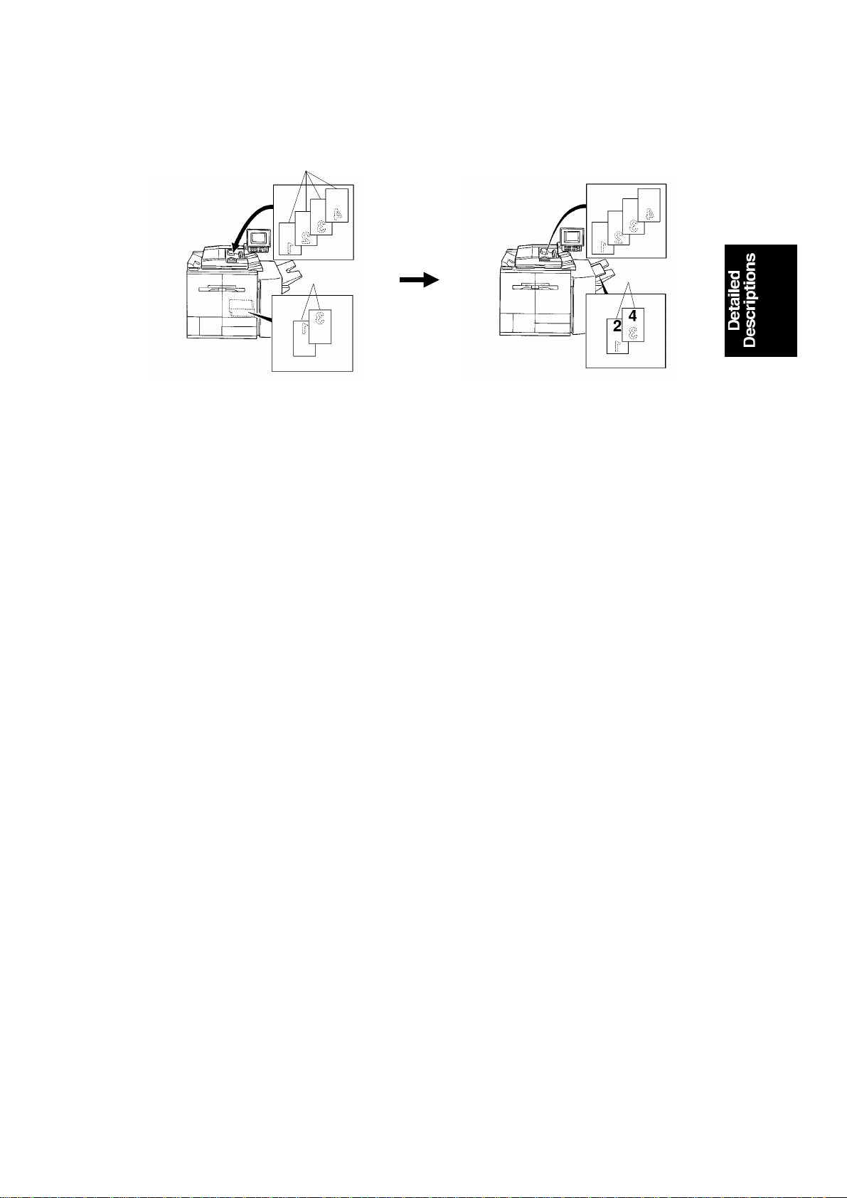
16.1.4 Two or More Copies (alternate paper feed)
An alternate paper fe ed system can be used when the RDH and Finishe r are
installed.
This alternate paper feed system is a relatively efficient way to make two or
more two-sided copies from two or more one-sided origin als whe n the cop ier
is equipped with an RDH.
No inversion original cycle is used for this mo de.
When making two-sided copies, first of all, the odd pages of the originals
placed on the RDH are copied on paper from th e paper t ray. They are then
stored in the duplex tray. Then the orig inals are recirculated, and the even
pages of the originals are copied on the sheets store d in th e du plex tray.
When making two or more sets of copies, the odd pages of the origin als are
copied and the copies are sto red in the duplex tray. Then all the pa ges o f th e
recirculated original are copie d. Odd pages are copied onto new copy paper.
Even pages are copied onto paper from th e duple x t ray. Finally th e eve n
pages of the recirculated originals are copie d on the sheets stored in the
duplex tray. See the next page for example.
This system has many benefits.
2-7
Page 25

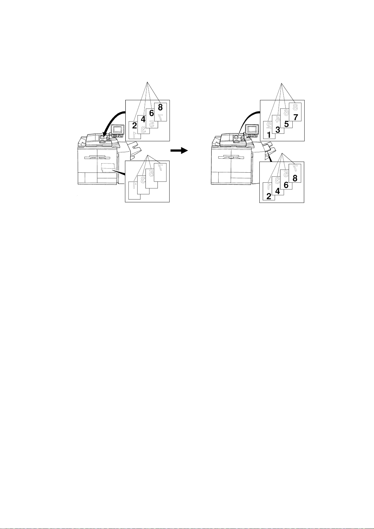
RDH 31 January 1996
– Operation –
Example:
Two sets of two-sided copies are made from four one-sid ed originals.
1) When the start key is pressed, th e 1st and 3rd orig inals are scanned,
then the copies are stacked in the duplex tray. The 2nd and 4th originals
have only passed over the expo sure glass [Fig 1].
2) The 1st original is scanned. The copy is stacked in the duplex tray.
Soon after this, the bo tt om copy in the duplex tray is fed [Fig 2].
3) The 2nd original is scanned. The copy which has been fed rea che s the
drum for copying the 2nd original, and is then fed out onto the copy tray
[Fig 3].
4) The 3rd original is scanned, and th e cop y is stacked in the duplex tray.
Soon after this, the bo tt om copy in the duplex tray is fed [Fig 4].
5) The 4th original is scanne d. The copy which has been fed reaches the
drum for copying the 4th original, and is then fed out onto the copy tray
[Fig 5]. The stack in the duplex un it is moved to the duplex paper feed
section by the duplex end fence.
6) The 1st original is fed into the scanner and is fed out from the RDH
without exposing. After this, the bottom cop y in the dup lex tra y is fed in
preparation for th e reve rse side copying [Fig 6].
7) The 2nd original is scanned. The copy which has been fed rea che s the
drum for copying the 2nd original, and is then fed out onto the copy tray
[Fig 6].
8) The 3rd original passes over the expo sure glass. Aft er this, the bottom
copy in the duplex tray is fed in preparat ion for the reverse side copying
[Fig 7].
9) The 4th original is scanne d, the copy which has been fed reaches the
drum for copying the 4th original, and is then fed out onto the copy tray
[Fig 7].
2-8
Page 26

31 January 1996 RDH
4
3
2
1
3
1
C
B
3
1
1
1
3
1
A
Fig 3Fig 2Fig 1
3
3
1
3
1
3
3
1
2
1
Fig 7
Fig 6Fig 5Fig 4
A: Paper Tray
B: Duplex Unit
C: RDH
3
1
m
: Recirculated
l
: 3rd recirculated
: Without exposing
(for RDH)
A170D506.wmf
2-9
Page 27
RDH 31 January 1996
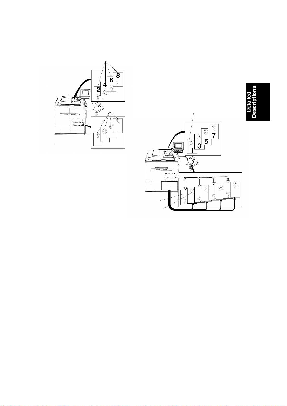
16.1.5 2 Sided Original 2 Sided Copy Mode
[A]
[B]
A170D507.img
[C]
[D]
A170D508.img
Inversion original cycle is used for this mode. All the origin als [A ] are fed
starting from the bottom o rigin al she et. First, the front side of the originals are
copied. The copied paper [ B] is stacked in the duplex tray. The originals [C]
are inverted and return to the origin al ta ble . The origin al fe ed is then
repeated. This time the reverse side of the originals are copied on the
reverse side of the copy paper [D], which is fed from the duplex tray.
2-10
Page 28
[E]
31 January 1996 RDH
16.1.6 2 Sided Original 1 Sided Copy Mode
[A]
[B]
A170D507.img
[D]
[C]
A170D509.img
Inversion original cycle is used for this mode. All the origin als [A ] are fed
starting rom the bottom original sheet. First ly, the fro nt sid e of all the originals
are copied and the cop ied pap er [B ] is st acke d in the duplex tray. The
originals [C] are inverted and re turn to the origin al ta ble . The origin al fe ed is
then repeated. This time, the bott om cop y sh eet is fed from th e duple x tr ay
and exited from the copier with ou t copying [C]. The reverse side of th e
bottom original sheet [D] is then copie d to paper [E ], which is fed from the
paper tray, and the copy is exited from the copie r [E] . This cop y se quen ce
exiting from the duplex tray followed by the paper tray is alte rna te ly repe ated .
2-11
Page 29
RDH 31 January 1996
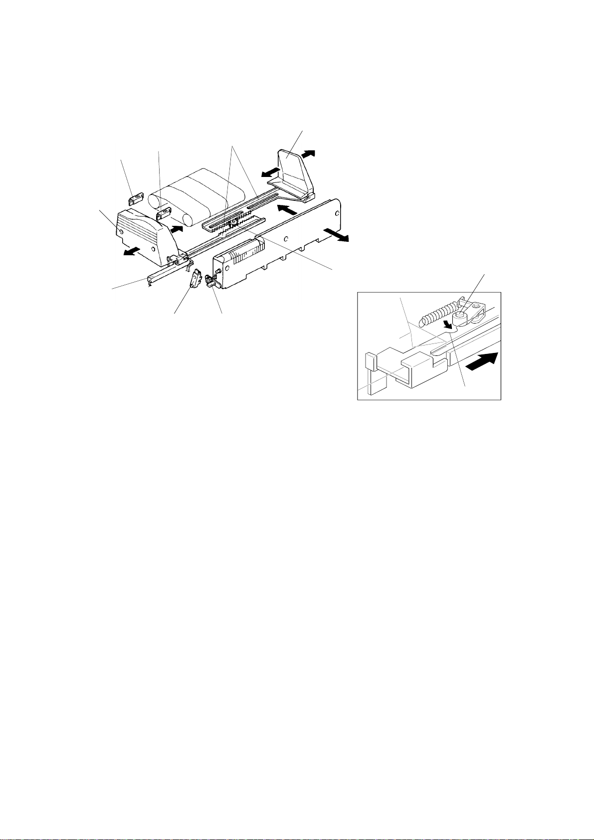
16.2 ORIGINAL SET
16.2.1 Stack Feed Mode
[D]
[B]
[A]
[D]
[E]
[G]
[J]
[C]
[I]
[H]
A170D510.img
[K]
1. Original set detection
A170D528.wmf
The originals are detected by the original set sensor [A] when they are
stacked on the original t ab le. If the original incorrect positio nin g sensor [B]
detects originals placed inco rrectly on the RDH original table, a messa ge is
displayed advising the user to set th e originals at the correct position.
2. Size detection
The original width is detected by the origin al width sensor [B] under the front
original guide [D]. Movin g the guide changes the value of th e sen sor. (The
sensor is a potentiometer.) Th e fro nt origin al gu ide and rear orig inal guide [E]
are moved by the racks [F] and pin ion [G] at the same time. The act ua to r [ H]
of the original stopper activat es th e original length sensor [I]
(photo-interrupte r) t o dete ct if the original stopper is set for the 81/2 inch
position. LG (81/2" x 14" = 216 x 356 mm) or B4 (257 x 364 mm) size is
distinguished by the combination of the origina l leng th se nso r (a ctiva ted or
not) and the value of the origin al widt h sensor. This is because the LG and
B4 widths are very close.
The original guides are stopped at the pape r size posit ion (A 4 for EU/LT, LG
for USA). They click into position when the roller [J] on the lock arm dro ps
into the semicircular stopper [K].
2-12
Page 30

[C]
31 January 1996 RDH
[B]
[E]
[E]
[A]
[D]
[F]
[E]
A170D511.img
A170D512.img
3. Original separator
The original stack which has been fed and return ed to the orig inal table, and
the original stack which has no t been fed yet, are separated by the original
separator [A] mechanism.
When the start key is pressed, the sepa rator motor [B] rotates un til th e
original separator act ua to r [ C] act ivates the separator home position sensor
[D]. The original separato r is set on the original top sheet. The originals which
are fed and returned to the origin al table are stacked on the original
separator. When the last original (to p sheet under the orig ina l sepa rat or) is
fed from the original table, the orig inal separator drops and activates th e
separator sensor [E].
If the next copy cycle continues, th e sep ara to r moto r rota te s and the origin al
separator is set on the original top sheet ag ain aft er th e tra iling edge of the
last original sheet passe s thro ug h the exit sensor [F].
2-13
Page 31

[E]
RDH 31 January 1996
16.2.2 Single Feed Mode
[A]
[C]
A170D513.img
[D]
[B]
[F]
A170D514.img
1. Original set detection
The original is detected by the single feed set sensor [A] when the original is
set on the single feed tab le.
2. Size detection
The original width is detected by the sin gle feed orig inal width sensor [B]
under the rear original guide [C]. Moving the guide chan ges t he value of th e
sensor. (The sensor is a potentiometer.) The front original guide [D] and rea r
original guide are moved by the racks [E] and pinion [F] at the same time. As
the original length sensor is not use d for t he single feed mode, the original
length is not detected . When the B4 or LG original is set on th e sing le feed
table, the origina l size is dete rmine d by the machine version.
(U.S.A. version machine ... LG, Euro pe version ma chin e .. . B4 ).
2-14
Page 32

31 January 1996 RDH
16.3 ORIGINAL FEED
16.3.1 Original Separation/Feed (Original Stac k Mode)
[A]
[B]
[E]
[F]
[D]
[B]
[C]
A170D515.img
[F]
[G]
[H]
A170D516.img
1. Air knife and shutter
The air from the blower motor [A] is blown thro ug h the air knif e nozzles [B] to
the leading edge [C] of the original stack. The blowe r moto r keeps blowin g air
from the beginning to the end of the origin al stack mode to prevent
multi-feeding.
After the originals are separated by the air knife, the vacuum shutter solenoid
[D] is energized by a paper feed signal from the main PCB. The vacuum
shutter [E] closes the air hole on th e vacu um du ct [F] . The blowe r draws air
from the vacuum section [F] . The botto m shee t orig inal [G] is held against the
feed-in belts by the suction . Until, the feed-in belt rotat es. The bottom sheet
original [H] is then fed.
2-15
Page 33

RDH 31 January 1996
[A]
Table 1
Table 2
Small
Size
Large
Size
Small
Size
Large
Size
A4
1/2
8 x 10
81/2 x 11
1/2 x 13
8
B4
A3
1/2 x 14
8
10 x 14
11 x 17
A4
1/2
8 x 10
81/2 x 11
1/2 x 13
8
B4
A3
1/2 x 14
8
10 x 14
11 x 17
A170D517.img
Original Height Sensor
OFF ON
3000 rpm
7000 rpm
3500 rpm
Number of Originals
5 or less from 6 to 12 13 or more
3000 rpm
7000 rpm
3500 rpm
2. Blower motor speed
To ensure good original separation and origin al re-st ackin g on the origin al
table, the blower motor speed is chang ed accord ing to the original stack
height, or the number of originals stacked. The blower motor speed is
determined for the 1st copy cycle by the original stack height as detected by
the original height sensor [ A] (Table 1). From th e 2nd cop y cycle, th e blo wer
motor speed is determined by the numbe r of orig ina ls coun te d by the main
PCB (Table 2).
When the number of the originals is 3 or less, the origin al set sensor is
de-activated when the last original is fed and before the 1st origin al ret urn s to
the original table. During this pe riod the blowe r motor stops rotating to ensure
correct stacking the originals.
2-16
Page 34

[D]
[E]
31 January 1996 RDH
16.4 SINGLE FEED MODE
16.4.1 Registration
[B]
[A]
[C]
[D]
A170D518.img
When the single feed set sensor [A] detects the leading edge of the orig ina l
the feed motor rotates and the right turn roller [B] transports the original. At
the same time the single fe ed gat e sole no id [C] is energized and the single
feed gate [D] is lowered. The feed mot or an d sing le fe ed gat e soleno id are
energized until the registration sensor [E] detects the leading edge of the
original. The original is transported until hits the single feed gate, which
corrects the original feed skew. At th e same time th e right turn roller stops
rotating.
2-17
Page 35

[B]
RDH 31 January 1996
16.4.2 Feed
[C]
[D]
[G]
[A]
[F]
[E]
A170D519.img
When the start key is pressed, the rig ht turn roller [A] and transport belt [B]
rotate. The origina l is delivered onto the exposure glass. Aft er the scanner
scans the original, the transpo rt be lt sta rt to ro ta te to deliver it. At the same
time the inverter entrance [C] an d inve rter middle [D] rollers rotate and the
single feed exit solenoid [E ] is ene rgized. The single feed exit gate [F ] lift s up,
exiting the original to the left top cover [G].
16.4.3 16.4.3 Exit Gate
In single feed mode and CFF mode , the single feed exit solenoid is ene rgize d
while the belt drive motor is driving the transport belt, and is de-energized
when the transport belt stops rotating. This solenoid on off operation is
performed to keep the solenoid reliable.
2-18
Page 36

[A]
31 January 1996 RDH
16.5 DRIVE MECHANISM
16.5.1 Feed Motor Drive
[B]
[G]
[C]
A170D520.img
[H]
[H]
[D]
[A]
[E]
[F]
[C]
A170D521.img
All the feed rollers and transport rollers (with the exception of the fee d belt
drive rollers [A]) begin to rotate to geth er with the feed mot or [B]. The feed belt
drive clutch [C] is energized accordin g to the appropriate original fee d timin g.
When the clutch is energized, the feed motor drive will be transmitt ed thro ugh
the gears [D] and timing belt [E] , an d th e feed belt brake clutch shaf t [F] to
the feed belt drive rollers. The feed belt bra ke clut ch [G] stops the feed belt
rotation when the feed belt drive clutch is de-energized to prevent
multi-feeding of originals. When the feed belt brake clutch is energ ized ,t he
rotating clutch disk [H] is stopped by the clutch which is fixed on the frame .
2-19
Page 37

RDH 31 January 1996
16.5.2 Belt Drive Motor Drive
[B]
[A]
A170D522.img
The transport belt [A] is driven by the belt drive mot or [B ] via timin g belts an d
pulleys.
2-20
Page 38

[H]
31 January 1996 RDH
16.5.3 Inverter Motor Drive
[A]
[C]
[B]
[D]
[E]
[F]
A170D522.img
[G]
[D]
[A]
A170D523.img
The inverter motor [A] rot at es fo rward s or b ackwa rds acco rding to the
appropriate timing. The invert er middle [B] and inverter [C] rollers ro ta te
forwards and backwards the inve rte r mo to r drive. However, inverter entran ce
[D], inverter exit [E], and exit [F] rollers rot at e in only o ne direct ion.
The relay pulley [G] and inverter roller pu lley [H] have a built - in one way
clutch inside. When the inverter motor rot at es forward s (b lack arro w
direction), the inverter rolle r pulley [H] rotates the inverte r ent ran ce roller [D].
In this case the relay pulley [G] freely rotates due to the one way clutch
inside. All rollers rotate in the original feed directio n.
While the inverter motor rotates backward s (white arrow dire ctio n), the relay
pulley [G] rotates the inverter entrance roller [ D]. In th is ca se th e inverter
roller pulley [H] freely rotat es due to the one way clutch inside. The invert er
entrance, inverter exit, and exit rollers rotate in the original exit direction.
However, the inverter middle and inverter rollers rotate in the original
switching back direction.
2-21
Page 39

RDH 31 January 1996
16.6 ORIGINAL POSITIONING
Thin Paper Mode
[A]
A170D524.img
Thick Paper Mode
A170D525.img
Customers can choose the paper tra nsp ort mode by "User Tool" depending
on the thickness of the original used.
– In thin paper mode –
The belt motor stops exactly when the trailin g ed ge of the original passes the
right scale [A] edge. (The timing is measu red by the timing sensor after
registration sensor is activated. )
– In thick paper mode –
To correct skewing on the exposure glass, the origin al runs 10 mm after the
trailing edge passes the right scale . The belt motor then reverses and the
original travels until it meets the right scale.
If extremely thin paper is used in the thick paper mod e, the paper may float
near the scale. This will result in poor image quality or original copy wrinklin g.
The factory setting is "Thin Pap er Mode:.
2-22
Page 40

31 January 1996 RDH
16.7 CFF Mode
[C]
[A]
[E]
[D]
[B]
A170D526.img
When the CFF guide lever [ A] is slid to the left, the CFF sensor [B] comes out
of the single feed rear guide [C]. This sensor consists of one CFF set sensor
[D] and two CFF feed hole sensors [E]. The CFF set sensor detects if the
computer form is set in the CFF guide.
The CFF feed hole sensor coun ts th e ho les line d up to th e computer form.
2-23
Page 41

A170D531.img
Energy Star Compliant Machines (North American versions only) 31 January 1996
19. Energy Star Compliant Machines (North
American versions only)
In conjunction with the modification for the Ene rgy St ar compliance, field
technicians are reque ste d to understand the changes in op eration modes so
as to set up the machine for the custo mer specific environment/require men ts.
The following table shows all diff erences between the Energy Star co mplia nt
machines and the Non-Energy St ar comp liant machines.
Mode Non-Energy Star Energy Star
Auto Off Mode When the copier is used after the
weekly timer has turned it off, the
copier will turn itself back off after
the selected time.
The auto off time can be set from 1
to 180 minutes, or the function can
be turned off.
Default: 1 hour
Simplex/Duplex
Mode
Weekly Timer Available Because the auto off mode is a
SC Code N/A A new SC code # 940 has been
Single sided original to single sided
copy is default setting mode at the
factory.
The copier turns off after the
selected time after the last copying
job.
The time can be adjusted from 1 to
120 minutes. This mode cannot be
canceled.
Default: 90 minutes
Single sided original to two sided
copy is default setting mode at the
factory.
mandatory standard feature of the
Energy Star standards, the weekly
timer is no longer available.
added.
Definition: The main switch does
not turn off after sending
the reset signal two times
in a row.
Point to check: • Main Switch
• Main PCB
Because the auto off mode and default duplex mode are explained in the
Operating Instru ctions, make sure that the cust ome r u nd erst an ds ho w the
machine operates to save en ergy.
2-24
Page 42

SECTION 3
INSTALLATION
Page 43

31 January 1996 INSTALLATION REQUIREMENT
1. INSTALLATION REQUIREMENT
1.1 ENVIRONMENT
1. Temperature Range: 10°C to 30°C (50°F to 86°F)
2. Humidity Range: 15% to 90% RH
3. Ambient Illumination: Less than 1,500 lux (do not exp osure to direct
sunlight)
4. Ventilation: Min imum spa ce 20 m3.
Room air should turn over at least
30 m3/hr/person.
5. Ambient Dust: L ess th an 0.1 5 mg/ m3 (4 x 10
6. If the machine location is a ir-con dit ioned or heated, place the machine:
a) where it will not be subjected to sudden temperature changes.
b) where it will not be directly exposed to cool air from an air-conditioner
in the summer.
c) where it will not be directly exposed to ref lect ed heat fro m a space
heater in winter.
7. Avoid placing the machine in an area filled wit h corro sive ga s.
8. Avoid any places higher than 2,000 meters (6,500 fee t) ab ove seal level.
9. Place the machine on a stro ng and level ba se.
10. Avoid any area where the machine may be frequently subje cte d to strong
vibration.
-6
oz/yd3)
1.2 MACHINE LEVEL
1. Front to back level: within 5 mm (0.2")
2. Right to left level: within 5 mm (0.2")
3-1
Page 44
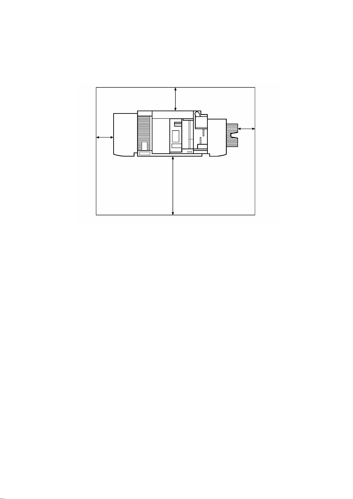
More than 11.8"
(300 mm)
INSTALLATION REQUIREMENT 31 January 1996
1.3 MINIMUM SPACE REQUIRE MENTS
More than 15.8"
(400 mm)
More than 11.8"
(300 mm)
More than 39.4"
(1000 mm)
A170I500.img
3-2
Page 45

31 January 1996 INSTALLATION REQUIREMENT
1.4 POWER REQUIREMENTS
1. Input voltage leve l:
240 V/60 Hz: 20A or more (for U.S.A. version)
220 V/230 V/240 V/50 Hz: 13A or more (for Eu rop ea n versio n)
2. Permissible voltage fluctuation: ±10%
3. Do not set anythin g on the power cord.
CAUTION:
N
a) Make sure the plug is firmly inserted in the outlet.
b) Avoid multi-wiring.
240V
(U.S.A. version)
220 / 230 / 240V
(European version)
3-3
A170I501.img
Page 46

ACCESSORY CHECK 31 January 1996
2. ACCESSORY CHECK
Check the quantity and condition of the accessories in the box acco rding to
the following list:
1. Operation Unit ................. .. ...................... 1
2. Operation Unit Stand..................... .. ........ 1
3. Fusing Unit Release Lever.............. .. .. .. .. 1
4. Drum Guide ......................... .. .. .. .. .. .. .... .. .. 1
5. Leveling Shoe.......................... .. .............. 4
6. Operating Instru ctio ns Holder ................. 1
7. Editing Sheet (U.S.A version only).......... 1
8. M4 x 6 Screw .................... ............ .......... 4
9. M5 x 8 Screw .................... ............ .......... 4
10. M3 x 10 Screw............................... .. ........ 2
11. M4 x 8 Screw ........ .. ............ ............ ........10
12. Harness Clamp...................... ............ ...... 2
13. Bushing ........... .............................. .. ........ 1
14. Operation Unit Sto pp e r................ .. .......... 1
15. Drum Guide Bracket........................ .. .. .. .. 1
16. Left Lower Inner Cover.................... ........ 1
3-4
Page 47

31 January 1996 INSTALLATION PROCEDURE (COPIER)
3. INSTALLATION PROCEDURE (COPIER)
[A]
[A]
[F]
[C]
[D]
[B]
A170I503.wmf
[G]
[H]
CAUTION:
N
A70I502.img
A170I504.wmf
While the leveling shoes are not i nsta ll ed, do not completely pull out
many units simultaneousl y. Otherwise, the machine could topple.
NOTE: Keep the shipping retain ers af ter installing the machine. They will be
reused if in the futu re the machine is transported to another location.
Proper reinstallation of th e ship ping retainers is required in order to
avoid any transport damage.
1. Remove the strips of the filament ta pe [A] .
[E]
[J]
[I]
2. Open the left and right front do ors [B , C] an d remo ve th e strip s of fila men t
tape [D]. Remove the styrofoam blocks [E] and the cushion [F].
3. Remove the left vertical transp ort fixing bracket [G] (1 screw), pull out the
left vertical transport unit , an d inst all th e lef t lowe r inne r cover [H] (2
screws).
4. Remove the tray fixing bracke t [I ] (1 screw) an d rein stall the removed
screw [J] on the 3rd tray cover.
3-5
Page 48

INSTALLATION PROCEDURE (COPIER) 31 January 1996
[B]
[G]
[F]
[A]
A170I505.img
[D]
[E]
[C]
A170I506.img
A170I523.img
[H]
[E]
A170I524.wmf
[I]
A170I507.wmf
5. Remove the fusing cover [A ] (3 screws), fixing bracket [B] (1 screw), and
reinstall the fusing cover. In stall the fusing unit release lever [C] , tu rn the
lever clockwise, and fix it (1 M5 x 8 screw).
(European version only)
a) Pull out the fusing unit.
b) Remove the upper fusing entra nce guide [D] (4 screws).
c) Remove the oil supply roller securing brackets [E] (2 screws).
d) While pushing the bushings [F] inwards, put back the screws [G].
e) Re-install the upper fusing entrance guide and push in the fusing unit.
6. Remove the right cover [H] (2 screws) an d 2 stu ds [I ] securing the paper
tray. Reinstall the right cover.
3-6
Page 49

31 January 1996 INSTALLATION PROCEDURE (COPIER)
[J]
[D]
[C]
[I]
[F]
[A]
[B]
[E]
A170I508.img
[L]
[N]
[G]
[H]
A170I509.img
[K]
[M]
A170I510.img
7. Remove the front scale holder [ A] (2 screws), fro nt scale [B] (2 screws),
exposure glass [C], left top cover [D] (8 screws), and right rear cover [E]
(front view, 2 screws).
8. Remove the 3rd scanner securing bracket [F] (1 screw), scanner securing
screw [G], and lens securing bracket [H] (1 screw).
NOTE: The scanner fixing screw is required when replacing the scanner
wire. Please keep it for future use.
9. Reinstall the exposure glass, fron t scale, front scale holder, and the left
top cover.
NOTE: • The mark [I] on the edge of the glass should face up. This side
is smoother and it generates less sta tic ele ctricity when the
DF is used.
• Use the flat head screw for 5 screws [J].
10. Remove the left inner cove r [K] (4 screws), strip of fila men t tape [L]. Then,
remove the PTC unit [M], and th e de velopment unit [N] (1 screw and 1
connector).
3-7
Page 50

[J]
INSTALLATION PROCEDURE (COPIER) 31 January 1996
[B]
[A]
A170I511.img
[I]
[D]
[C]
A170I512.img
[F]
[H]
[G]
[E]
A170I513.img
11. Remove the charge corona unit [A] (1 connector and 1 clamp) and erase
unit [B].
12. Lower the transport unit by the lever [C] as shown and remove the drum
stay [D] and cleaning unit [E].
13. Remove the drum potential se nso r [F] (2 connectors), ID sensor [G], and
drum protection sleeve [H].
14. Reinstall all the units arou nd the drum exce pt for th e de velo pment unit
and PTC unit.
NOTE: Press the drum shaft [I] to the left and align the clean ing unit to
the guides [J] to prevent th e dru m dama ge when reinstalling the
cleaning unit.
3-8
Page 51

31 January 1996 INSTALLATION PROCEDURE (COPIER)
[A]
A170I514.img
A170I515.img
15. Remove the developme nt filter [A] from the developme nt unit .
16. Pour the developer (1 bag: 1.7 kg) evenly between the left and right side
of the development unit and rein sta ll the deve lop ment filter. Then,
reinstall the developmen t unit (1 connector and 1 screw), and PTC unit on
the copier.
17. Load toner as follows (refer to the instruction decal):
a) Shake a new toner cartridge well while holding it horizonta lly.
b) Turn the green lever clockwise.
c) Insert the cartridge an d ret urn the green lever to the down po sitio n.
d) Cut the green tape.
e) Press down tab 1 and pull shutter 2 until you see the gre en tab 3.
f) Grasp tab 3 and pull the seal until yo u see the re d line .
g) Push the shutter back in.
18. Install the left inner cover an d set the tran spo rt un it.
3-9
Page 52

INSTALLATION PROCEDURE (COPIER) 31 January 1996
[B]
[E]
[F]
[C]
[A]
A170I516.img
[D]
[G]
A170I517.img
19. Connect the operation unit [A ] to the operation unit stand [B] (4 screws
and 2 connectors).
20. Install the operation unit (1 M5 x 8 screw [C] and 1 connect or [D]) and the
operation unit stopper [E] (2 M5 x 8 scre ws). The oval hole [F] of the
operation unit stopper should be at the lower position.
NOTE: • 2 height positions of the oper at ion unit can be selected by the
positions of securing screw [C].
• The operation unit can be moved le ft to righ t by removing one
M5 x 8 screw [C] when the operation unit is mounted at the
lower position.
21. Secure the grounding wire [G] of th e op era tio n un it (1 screw) an d rein sta ll
the right rear cover.
3-10
Page 53

31 January 1996 INSTALLATION PROCEDURE (COPIER)
[B]
[A]
A170I518.img
c
[C]
1
0
A170I519.img
[D]
[E]
A170I525.wmf
23. Insert the leveling shoes [A] under the feet, and level the machine by
securing down the feet.
24. Guidance ROM Kit installation (-27 versions only). Remove the operation
unit rear cover [B] (4 screws) and install the appropriate ROMs [C] to the
operation unit board . Distin gu ish the chips (0, 1, and c) by the last 2 digit s
of their part number. The lowest one is installed at 0, the mid dle one at 1,
the highest one at c.
25. Reinstall all the covers.
26. Install the copy tray or follo w t he finish er un it inst allation.
27. Plug in the power cord and turn on the main switch.
28. Install the drum guide bracket [D] (1 long screw) (Replace the screw with
long one.) and set the drum guide [E].
29. Check the copy quality and the copier operation.
3-11
Page 54

INSTALLATION PROCEDURE (COPIER) 31 January 1996
3.1 A3/11" x 17" COUNTER INSTALLATIO N
[A]
[B]
[C]
A170I520.img
CAUTION:
N
Unplug the copier power cord before starting the following procedure.
1. Open the right fron t do or an d remo ve the right inner cover [A] (3 screws).
2. Install the A3/11" x 17" counter [B] (1 connector).
3. Cut the cap [C] of the righ t inner cover by the pliers.
4. Reassemble.
5. Plug in the copier power cord and turn on th e main switch.
6. Set the A3/1 1" x 17" counter mode on by using SP mod e.
7. Check the counter ope rat ion by making an A3/11" x 17" copy.
3-12
Page 55

[I]
31 January 1996 INSTALLATION PROCEDURE (COPIER)
3.2 KEY COUNTER HOLDER INSTALLATION
[C]
[H]
[F]
[B]
[A]
A170I522.img
CAUTION:
N
A170I521.img
[J]
[E]
Unplug the copier power cord before starting the following procedure.
NOTE: The Key Counter Bracket Set includes the following part s. The key
counter holder and key counter should be procured locally.
1. Key Counter Bracket............. .. ............ .. .. ..........1
2. Key Counter Plate Nut.......................................1
3. Key Counter Cover.................. ............ .. .. ..........1
4. Bushing..............................................................1
5. Screws...............................................................8
6. Clamp................................................................1
1. Open the right front door an d remo ve the right inner cover (3 screws).
[G]
[D]
2. Remove the dummy connector [A].
3. Remove the right cover [B] (2 screws) a nd sma ll cap [C] .
4. Connect the key count er ho lder [D] to key counter bracket [E] with key
counter plate nut [F] (2 screws).
5. Run the key counter harn ess [G] through the bushing [H] an d right cover
hole [I] and fix the key counter ha rne ss (1 screw and 1 harness clamp).
6. Install the key counter bracket to the right cover (3 screws).
7. Set the key counter ha rne s s conn ect or to the 4P connector from the
copier.
8. Reinstall the right cover.
9. Install the key counter cover [J] (2 screws).
10. Reassemble the machine.
3-13
Page 56

INSTALLATION PROCEDURE (LCT) 31 January 1996
4. INSTALLATION PROCEDURE (LCT)
[C]
[A]
Check the quantity and condition of the accessories in the box acco rding to
the following list.
[A]
[E]
[B]
A592I506.wmf
[D]
A592I500.img
1. By-pass Feed Lower Cover
(European version only) ..........................................1
2. By-pass Rear Lower Cover
(European version only) ..........................................1
3. Screw-M4 x 8 (Eropean version only)................... ...3
4. Grounding Screw-M4 x 8............... ............ ............ ...2
5. Screw-M4 x 12........................... .. .. .... .. .. .. .. .. .. .... .. .. .. .1
CAUTION:
N
Unplug the copier and 2nd sorter power cord starting the following
procedure.
1. Remove the strips of filament tape [A] of LCT.
2. Open the top cover [B] and remove the up per cover [C] (6 screws).
3. Remove the rear cover [D] (2 screws).
4. Remove the fixing plate [E] (3 screws).
3-14
Page 57

[H]
31 January 1996 INSTALLATION PROCEDURE (LCT)
[F]
[C]
[D]
[G]
[B]
[A]
A592I501.img
A592I507.wmf
[E]
[D]
A592I505.img
5. Remove the left lower cover [A ] (3 screws) of the copier and remove the 3
caps [B]. Remove the upper by-pa ss f eed cove r [C] (2 screws: Non
by-pass feed version only) and lower by-pass feed cover [D] (2 screws).
6. Remove the left rear cover [E] of the copier and cut 2 binds [F] for the
LCT interface harness by th e plie rs.
7. Remove the dummy connector [G].
NOTE: The dummy connector is required when operating the copier
without the LCT. Keep it for future use.
8. Secure the ground wire [H] to the copier (1 grounding screw).
3-15
Page 58

[A]
[J]
A592I504.img
INSTALLATION PROCEDURE (LCT) 31 January 1996
[C]
[F]
[E]
A592I503.img
[B]
[G]
A592I508.wmf
[D]
[I]
A592I502.img
[H]
9. Reinstall all the LCT covers.
10. Install the LCT grounding wire [A] (1 grounding screw).
11. Pass 4 connectors of the inte rface harness [B] through the rear upper
hole [C] of the left lower cover, pass the grounding wire [A ] unde r t he left
lower cover, and install the left lower cove r. (Do no t fix th e screw [D].)
[G]
12. (By-pass feed version only) Insta ll t he by-pa ss f eed lowe r cover [E]
(2 screws) and by-pass rear lower cover [F] (1 screw).
13. Loosen th e nu ts [G] of the feet [H] .
14. Set 4 connectors to th e con ne ctors [G] of the LCT harness.
15. Mount the LCT unit on the copier (Insert the 2 mounting studs [I] into the
docking holes [J]).
16. Fix the LCT unit to the copier (1 screw [D]).
17. Screw down the feet [H] to level the LCT so that th e LCT is p ara llel to the
copier.
18. (Non by-pass feed version only) Reinst all th e up per b y-pa ss fee d cove r.
19. Carry out the LCT Paper Feed Timing Adjust men t by usin g SP mode
(9 SP Adjustment, 9-1 Paper Fee d Timing Adju stme nt : LCT).
20. Check the LCT operation.
3-16
Page 59

SECTION 4
SERVICE TABLES
Page 60

31 January 1996 SERVICE REMARKS
1. SERVICE REMARKS
1.12 RDH
1. Take care not to damage the harnesses of the original tab le by pu lling
roughly when you remove the orig ina l tab le.
2. Take care not to injure yourself by dropping the RDH unit when removing
it.
3. After replacing the RDH main PCB or RDH RAM boa rd, perf orm the RDH
motor adjustment, RDH registration adjustment, and CFF registration
adjustment. (This allows the RDH t o communicate with the copier main
PCB.)
1.13 FINISHER
1. Do not turn on the main switch while the shift tray is not installed. Both the
stack height sensor and the shift tray upper limit switch do not work
without the shift tray, an d causes the tray lift mechanism b roke n.
2. Before removing the timing belt s, mark th e po sitio n of the tension
brackets.
4-1
Page 61

SERVICE PROGRAM MODE 31 January 1996
2. SERVICE PROGRAM MODE
2.1 SERVICE PROGRAM MODE OPE RATION
The service program (SP) mode is used to che ck electrical data and change
modes or adjustment values.
2.1.1 To Access SP Mode
1. Turn on DIP SW #3 on the Reset Switch PCB.
2. Input "99900 " usin g the number key tops on the operation unit, the n th e
index menu of SP modes is displa yed.
3. Touch a number on the disp lay to access the required funct ion.
NOTE: While any of the following conditions exist, you can no t access the SP
mode.
1. Toner end
2. Paper jam
3. Machine error or service call (SC)
4. Door open
2.1.2 To Exit SP Mode
1. Return to the index menu by touching on the display.
2. Touch .
Quit
Index
3. Turn off DIP SW #3 on the Rese t Swit ch PCB.
2.1.3 Change the Menu Screen
1. To move to the next page , touch .
2. To move to the previous pag e, tou ch .
3. To return the index menu , to uch .
Next Pg.
Prev. Pg.
Index
A170M500.img
4-2
Page 62

31 January 1996 SERVICE PROGRAM MODE
2.2 SP MODE FUNCTION
1 Jam Counters
A170M501.img
A170M502.img
Location Code
A 1st Tray
B 2nd Tray
C 3rd Tray
D Not used
E Horizontal Transport Unit
F Registration
G Paper Separation
H Fusing Unit
I Paper Exit
1 Duplex Entrance
J
2 Duplex Paper Feed
J
K Duplex Exit
S By-pass Feed Table
U LCT
R1 Finisher Entrance
R2 Finisher Exit
R3 Jogger Unit Entrance
R4 Jogger Unit
A170M542.img
P1 RDH Feed-in
P2 RDH Transport Unit
P3 RDH Feed-out
A170M503.img
NOTE: To clear the counters, use SP mode (Counter Clea r).
4-3
12
Page 63

SERVICE PROGRAM MODE 31 January 1996
2 Daily / Weekly Jam Counters
Week 1 means the first week of a
month
Counters are not cleared at the end
of the week or month.
For example, if this menu is
A170M504.img
displayed on Monday, th e cou nters
of Tuesday through Friday show the
data for the previous week.
A170M505.img
A170M506.img
NOTE: To clear the counters, use SP mode (Counter Clea r).
12
4-4
Page 64

SET
31 January 1996 SERVICE PROGRAM MODE
3 Copy Counters
A170M507.img
A170M508.img
A170M543.img
The test mode copy counter displays
the number of copies in SP Test
Mode .
8
This counter only counts up when
Test Copy Counter ON is
(SP mode PAGE 5).
10
The block copy counter disp lays the
number of copies made since a
block copy counter clear was done
(SP mode PAGE 3). Use the
11
block copy counter display when the
machine is connected to a Remo te
Diagnostic System.
NOTE: 1. To clear the counters, use SP mode Counter Clear).
12
2. The total number of copies can only be cle are d by perfo rming the
RAM clear.
4-5
Page 65

SERVICE PROGRAM MODE 31 January 1996
4 Daily/Weekly Copy Counters
A170M509.img
NOTE: To clear the counters, use SP mode (Counter Clea r).
12
5 Operating Time
This displays the total rotation time of
the main motor. Minutes are not
displayed.
A170M510.img
NOTE: This counter can only be cleared by RAM clear.
(Main board DIP SW #1: ON, #2: OFF)
4-6
Page 66

31 January 1996 SERVICE PROGRAM MODE
6 SC Counters
A170M511.img
A170M512.img
A170M514.img
A170M516.img
A170M513.img
A170M518.img A170M515.img
NOTE: To clear the counters, use SP mode (Counter Clea r).
12
4-7
A170M517.img
Page 67

SERVICE PROGRAM MODE 31 January 1996
7 Sensor Outputs
ID Sensor
A170M519.img
Vsg
Vsp ID sensor output for pattern
ID sensor output for bare drum
surface
Drum Potential Sensor
Vd set up value during the
Vd
process control sequence
VL1
VL2 VL value during the copy cycle
V
V
VL set up value during the
process control sequence
Residual voltage during the
Vr
process control sequence
Potential sensor output when
100
100V is applied to the drum shaft
Potential sensor output when
800
800V is applied to the drum shaft
Drum potential just after charging
01
V
during the process control
sequence
Drum potential just after charging
02
V
during the copy cycle
Exposure Sensor
Initial
Current Current value
Initial value during the process
control sequence
ADS Sensor
ADS sensor output value during
Vs
the process control sequence
ADS sensor output value during
Vo
the copy cycle
Development Bias
Latest output of the development
Vb
bias during a copy cycle.
4-8
Page 68

31 January 1996 SERVICE PROGRAM MODE
Sensor Output-Sta ndar d Data
The ranges of items in the sensor output of the SP mode are as fo llows:
During process control During copying Remarks
Vsg 3.7 ~ 4.3 3.8 ~ 4.2 Lower than 2.5
(SC353)
Vsp
V100 0.10 ~ 1.00 —
V800 2.00 ~ 3.92 —
Vd
VL1
VL2
Vr
V01
V02
Exposure Sensor 1.6 ~ 3.5 (Initial) 1.6 ~ 3.5 (Current)
ADS Sensor 2.7 ~ 3.6 (Vs) 1.0 ~ 3.6 (Vo) Vo depends on the
Exposure Lamp
Heater Temperature
Vd = (Vr + 770) ± 5%
VL1 = (Vr + 50 – 10n) ± 5%
VL2 ≤ VL1 + 100
Vr ≤ 250
Vd ≤ V01 ≤ Vd + 100
V01 – 30 ≤ V02 ≤ V01 + 100
45 ~ 60°C
—
0.2 ~ 0.5 Higher than 1.4
(SC352)
Out of range (SC307)
Out of range (SC108)
originals.
Paper Feed Time
Displays the interval bet wee n the
time a paper feed clutch turns on and
the time the registration sensor turns
on.
Reference Times (theoret ical valu es
assuming no paper slippage):
If the displayed time varies by more
than 32 ms, check the appro pria te
feed clutch if the clutch disk surface
A170M520.img
is dirty.
(ms)
1st Tray 1,336
2nd Tray 1,617
3rd Tray 620
By-pass 444
Duplex Tray 1,741
LCT 730
4-9
Page 69

SERVICE PROGRAM MODE 31 January 1996
8 SP Test Mode – 1 (PAGE 1 - 1)
A170M521.img
Sensors
Turns on and off the 12-volt line of the dc drive board (CN302-2), which
applies power to the sensors, and checks sensor operation. The sensors
which are normally activated during the sta nd-by condition cannot be
checked because sensor output does not change.
Touch on the display. The copier automatically checks the sensors
START
and displays defective sensor co de numb ers (maximu m 5 senso rs).
Sensor Code Number
110 Paper Feed Sensor: 1st tray
111 Upper Limit Sensor: 1st tray
112 Lower Limit Sensor: 1st tray
113 Paper End Sensor: 1st tray
120 Paper Feed Sensor: 2nd tray
121 Upper Limit Sensor: 2nd Tray
122 Lower Limit Sensor: 2nd tray
123 Paper End Sensor: 2nd tray
130 Paper Feed Sensor: 3rd tray
131 Upper Limit Sensor: 3rd tray
132 Lower Limit Sensor: 3rd tray
133 Paper End Sensor: 3rd tray
150 Paper Feed Sensor: LCT
151 Upper Limit Sensor: LCT
152 Lower Limit Sensor: LCT
153 Paper End Sensor: LCT
160 Paper Feed Sensor: Duplex
165 Duplex Entrance Sensor
170 Paper Feed Sensor: By-pass Table
400 Fusing Sensor
500 Exit Sensor
800 Toner Cartridge Sensor
4-10
Page 70

31 January 1996 SERVICE PROGRAM MODE
8 SP Test Mode – 2 (PAGE 1 - 2)
A170M521.img
Solenoids/Clutches
Turns on and off the 24-volt lines to the solen oid s and clutch es from the main
board, and checks component activit y by mo nit orin g th e ele ctrica l current .
Touch on the display. The copier automatically checks the
START
components and displays defective component code numbers (maximum 5
components).
Solenoid/Clutch Code Number
100 Pick-up SOL: 3rd tray
104 Paper Feed CL: 3rd tray
105 Vertical Drive CL: Left
106 Registration CL
200 Pick-up SOL: 1st tray
204 Paper Feed CL: 1st tray
205 Vertical Drive CL: Right
208 Pick-up SOL: 2nd tray
212 Paper Feed CL: 2nd tray
300 Pinch Roller SOL
301 Inverter Gate SOL
302 Junction Gate SOL
304 Duplex Paper Feed SOL
308 Pressure Plate SOL
309 Positioning SOL
408 Cleaning SOL
410 Right Scale SOL
411 LCT Lock SOL
500 Pick-up SOL: LCT
504 Paper Feed SOL: LCT
505 Paper Feed MC: By-pass Table
506 Stopper SOL: By-pass Table
507 Pick-up SOL: By-pass Table
510 Relay MC: By-pass Table
4-11
Page 71

RESET
SERVICE PROGRAM MODE 31 January 1996
8 SP Test Mode – 3 (PAGE 1 - 3)
A170M521.img
Item Function Test Method
Charge Cleaner Turns on the charge and T/S
corona wire cleaners (one cycle).
ID Sensor Adjusts Vsg automatically and
makes an ID sensor pattern, then
checks Vsp .
ADS Sensor Adjusts the ADS sensor
automatically and measures the
original background density.
Drum Potential
Sensor
Exposure Lamp Turns on the exposure lamps and
Applies 100 V and 800 V to the
drum drive shaft from the
development bias power pack and
measures V
measures the lamp intensity
sensor value.
100 and V800.
Touch .
Note: The test result can be
displayed in Sensor Output
(SP mode ).
START
1. Touch on the display.
2. Press the "Start" key top on
the
operation unit.
1. Touch to turn on the
lamps.
SET
7
SET
4-12
2. Touch to turn off the
lamps.
Note: The test result can be
displayed in Sensor Output
(SP mode ).
7
Page 72

31 January 1996 SERVICE PROGRAM MODE
8 SP Test Mode – 4 (PAGE 2)
A170M522.img
Test Procedure
Touch on the display and press the "STA RT" key top to start.
Touch or press the "CLEAR/STOP" key top to stop.
Drum Conditioning
Mode
Free Run Mode
(Lamp ON)
Free Run Mode
(Lamp OFF)
Scanner Free Run
Mode
RDH Free Run
Mode
CFF Free Run
Mode
Fusing Pressure
Check Mode
SET
RESET
Item Function Remarks
Turns on the main motor, the
development drive motor, corona
power packs, and the erase lamp.
Operates the copier without
feeding paper.
Operates the copier without
feeding paper or turning on the
exposure lamp.
Runs the scanner unit.
Feeds originals automatically
without main copier operation.
Feeds CFFs (computers forms)
automatically without main copier
operation.
During the copy cycle, the
machine stops a copy stops in the
fusing unit for 15 seconds.
Place sheets of white paper (A3 or
11" x 17") on the exposure glass.
Do not operate the machine in this
mode for a long time.
Before testing, place originals in
the original table. The test is
finishes when all originals are fed
out.
Before testing, place CFFs in the
original table. The test is finished
when all CFFs are fed out.
Select a paper tray before
accessing the SP mode and open
document feeder to makes a sky
shot.
4-13
Page 73

SERVICE PROGRAM MODE 31 January 1996
8 SP Test Mode – 5 (PAGE 3)
A170M523.img
Test Procedure
Touch on the display and press the "STA RT" key top to start.
Touch or press the "CLEAR/STOP" key top to stop.
Cleaning Blade
OFF Mode
Process Control
Initial Setting
Toner Forced
Supply Mode
SC Detection OFF
Mode
Jam Detection
OFF Mode
Auto Drum Current
Adjustment Mode
SET
RESET
Item Function Remarks
Turns off the cleaning blade. This mode is only effective during
SP mode.
Start the process control data
initialization.
Use free run mode (lamp on) at
the same time. Supplies toner at
the 30% setting.
Disables SC detection. This is
only effective during SP mode.
Disables jam detection. This is
only effective during SP mode.
Enables adjustment of the T/S and
PTC power pack outputs during
process control initial setting.
To avoid over-toning, stop
periodically (about every 20
cycles) and check the copy quality.
Default: RESET
Use this function only after
replacing a power pack.
Otherwise, power pack outputs
may not set to the proper value.
4-14
Page 74

31 January 1996 SERVICE PROGRAM MODE
8 SP Test Mode – 6 (PAGE 4)
A171M551.img
Test Procedure
Touch on the display and press the "STA RT" key top to start.
Touch or press the "CLEAR/STOP" key top to stop.
Finisher Motor Test
Mode
Finisher Free Run
Mode
SET
RESET
Item Function Remarks
Operates the finisher drive motors
in sequence.
Operates the finisher without
feeding paper.
The transport drive, stack feed,
and exit drive motor speeds are
adjusted automatically.
4-15
Page 75

SERVICE PROGRAM MODE 31 January 1996
9 SP Adjustment – 1 (PAGE 1, 2, and 3)
A170M524.img
A170M525.img
1. Function
Turn on the individual power pack. Two or more powe r packs cannot be
turned on at the same time in th is mo de .
2. Test Procedure
Touch to turn on and touch to turn off.
SET RESET
NOTE: This mode may damage the drum; so, do this only with an old drum.
3. Code Table
C Charge corona
T1 Transfer corona - first side
T2 Transfer corona - second side
T3 Transfer corona - leading edge
T4
PTC Pre-transfer corona
D1 Separation corona - first side
D2 Separation corona - second side
D3 Separation corona - leading edge
D4
Transfer corona - leading edge
(translucent paper.)
Separation corona - leading edge
(translucent paper.)
Use to adjust an output voltages
from the power packs. Output values
change by 0 .5% per step .
NOTE: This adjustment should only
be carried out when the
RAM clear has to be done.
Do not use this mode in the
field except for the RAM clear
procedure.
4-16
A170M526.img
Page 76

31 January 1996 SERVICE PROGRAM MODE
9 SP Adjustment – 2 (PAGE 4)
A170M527.img
± 7
Change/
Step
Approx.
2 mm
30 V
1.3%
Approx.
1°C
20 V
(Vd)
15 V
B, VL1)
(V
+
Delay ON
timing
Lighter
Increase
light
intensity
Lower
temperature
Lower
voltages
Item Function Range
Transfer/Separation
Corona ON Timing
Adj.
ADS Sensor
Adjustment
Exposure Lamp Adj. Adjusts the light intensity of the
Fusing Temperature
Adj.
Latent Image
(Vd, Vb,Vl) Adj.
Changes the ON timing of normal
separation corona after leading edge
separation.
Changes the range of the ADS
voltage for ADS compensation.
exposure lamp.
Adjusts the hot roller temperature.
Use this mode with a thermometer.
Reduce Vd, Vb, and V
the charge corona from arching
abnormally (causing black spots on
copies) in high altitude areas.
L1 to prevent
± 16
± 16
± 16
0 ~ 9
ADS Sensor Adjustment
NOTE: For factory use, VBA + VBADJ can be reduced below 0 V using the
ADS sensor adjustment for testing in SP mode. Check the copy
quality in ADS mode after exiting the SP mod e. For rout ine
operation, VBA+ VBADJ is limited to 0 V or more. In the field, adjust
the ID selection in ADS mode (V BS, SP Special Features: Index
10
4-6).
4-17
Page 77

SERVICE PROGRAM MODE 31 January 1996
9 SP Adjustment – 3 (PAGE 5)
A170M528.img
Item Function Range
Horizontal Magnification
Adjustment (Full Size)
Horizontal Magnification
Adjustment (50%)
Horizontal Magnification
Adjustment (200%)
Focus Adjustment
(Full Size)
Focus Adjustment
(50%)
Focus Adjustment
(200%)
Vertical Magnification
Adjustment
Adjustment Standards
Magnification
Adjusts the lens and the mirror unit
vertical stop position at the full size.
Adjusts the lens and mirror unit
vertical stop position at 50%.
Adjusts the lens and the mirror unit
vertical stop position at 200%.
Adjusts the stop position of the
mirror unit.
Adjusts the stop position of the
mirror unit.
Adjusts the stop position of the
mirror unit.
Adjusts the main motor speed.
(Affects all reproduction ratios.)
±0.5% (Full Size)
±1% (Enlarge/Reduction)
± 16
± 32
± 3
Change/
Step
0.4 mm
0.3%
+
Enlarge
side
—
4-18
Page 78

31 January 1996 SERVICE PROGRAM MODE
9 SP Adjustment – 4 (PAGE 6)
A170M529.img
Item Function Range
Leading Edge
Registration Adj.
Leading Edge
Erase Adj.
Scanner Motor Gain
Adjustment
Changes the ON timing of the
registration clutch.
Changes the leading edge erase. Approx.
Factory use only.
Adjustment Standards
Leading Edge Registration
Leading Edge Erase
Side to Side Registration
± 16
0 ± 2 mm/0 ± 0.08" (Platen/Full Size)
4 ± 3 mm/0.16" ± 0.12" (50 ~ 150%)
6 ± 3 mm/0.24" ± 0.12" (151 ~ 200%)
0 ± 2 mm/0 ± 0.08" (Platen/Full Size)
Change/
Step
Approx.
1 mm
1 mm
——
+
Delay paper
feeding
Widen erase
width
4-19
Page 79

SERVICE PROGRAM MODE 31 January 1996
9 SP Adjustment – 5 (PAGE 7)
A170M530.img
This page is for the original moving scan mode of type Y. This is not used for type X.
4-20
Page 80

31 January 1996 SERVICE PROGRAM MODE
9 SP Adjustment – 6 (PAGE 8)
A170M531.img
Item Function Test Procedure
RDH Motor
Adjustment
Item Function Range
RDH Registration
Adj.
CFF registration
Adjustment
Adjusts the paper feed motor, transport
motor, and inverter motor speed of the
document feeder automatically.
Adjusts the original stop position.
Adjusts the CF stop position
± 16
Touch
Change/
0.75 mm
START
Step
Moves
original
away from
the right
scale.
+
Front Staple
Position Adj.
Rear Staple
Position Adj.
Adjusts the front staple position.
Adjusts the rear staple position.
0 ~ 20
1 mm
1 mm
Move to
rear
Move to
rear
Adjustment Standards
RDH Registration
CFF Registration
+4 mm
0
−2 mm
+3 mm
0
−1 mm
0 ± 2 mm/0 ± 0.08" (2nd ~ Last-1)
⁄ 0
⁄ 0
+0.16′′
(Thin mode)
−0.08′′
+0.12′′
(Thick mode)
−0.04′′
NOTE: Make a copy after changing RDH registration or CFF registration SP
data for adjusting registration. This allows the RDH to communica te
with the copier main PCB.
4-21
Page 81

SERVICE PROGRAM MODE 31 January 1996
9 SP Adjustment – 7 (PAGE 9)
A170M532.img
Item Function Range
Paper Feed Timing
Adjustment
Adjusts the amount of paper buckle
at the registration rollers for each
paper feed. When the registration
clutch, paper feed or duplex feed
clutch, or the paper feed or duplex
feed roller is replaced, check the
amount of paper buckle.
± 99
Change/
Step
Approx.
1 mm
+
Increase
amount
4-22
Page 82

31 January 1996 SERVICE PROGRAM MODE
9 SP Adjustment – 8 (PAGE 10)
Item Function Range
Jogger Span
Adjustment (Duplex
Jogger Fence
Adjustment)
A170M533.img
A170M534.img
Adjusts the jogger position of the
jogger fence for each paper size.
± 16
Change/
Step
0.6 mm
A170M544.img
A170M545.img
+
Widens the
span
4-23
Page 83

SERVICE PROGRAM MODE 31 January 1996
10 SP Special Feature – 1 (PAGE 1)
A170M535.img
<PAGE 1>
Item Function Setting Default
Fusing Lower
Temperature
Limit: High
Mode
A3/11 x 17
Counter ON
Mode
Select lower limit
temperature to enter
idling.
Increment option
counter when A3 or
11" x 17" copy is
made.
RESET
SET
RESET
SET
170°C (Cover Mode - 170°C) – LT
175°C (Cover Mode - 175°C) – A4
175°C (Cover Mode - 180°C) – LT
180°C (Cover Mode - 185°C) – A4
Optional counter not connected.
Optional counter connected.
RESET
RESET
Access Code Registers key
operator access
code for Accounting
Mode (User Tool 9
and 10).
PM Alarm
Enable
Set PM interval to
display "PM call"
when the PM
counter reaches PM
alarm level.
To register the access code, press the
"Access Code" key, input a 4 digit of access
code, and press "Access Code" key to
store it. The user must input this access
code before entering User Tools 9 and 10.
SET
(1K to 9999K)
SET
NOTE: When the high temperature mode is selected using a user tool, the
lower limit temperature is increased by + 5°C.
4-24
Page 84

31 January 1996 SERVICE PROGRAM MODE
SC Telephone No.
1. Touch .
SC Telephone No.
2. Enter the number by pressing the number key tops.
(Touch to input a dialing pause)
3. Touch .
–
SC Telephone No.
Serial No.
1. Touch .
Serial No.
2. Enter the machine serial number by pressing the number key tops.
3. Touch .
Serial No.
4-25
Page 85

SERVICE PROGRAM MODE 31 January 1996
10 SP Special Features – 2 (PAGE 2)
A170M536.img
Item Function
3rd tray does not have a paper size
Tray 3
sensor. To indicate the paper size on
the screen select a paper size.
A170M550.img
4-26
Page 86

31 January 1996 SERVICE PROGRAM MODE
10 SP Special Features – 2 (PAGE 3)
A170M540.img
Item Functio n Default Remarks
Tray Priority Select feed station at power
on or after reset.
No Select
No Select
selects 3rd tray
without LCT or LCT.
4-27
Page 87

SERVICE PROGRAM MODE 31 January 1996
10 SP Special Features – 3 (PAGE 4)
A170M537.img
Item Function Setting Default
Process Control
OFF Mode
Process Control
Auto Start Mode
Disables process control. Enable
To maintain optimum copy quality,
process control automatically works
at 12 o’clock midnight even if the
main switch is not turned off.
RESET
SET
RESET
SET
Disable
No
Yes
RESET
RESET
Fusing Idling
Mode
Toner Density
Selection
Toner Supply
Amount
ID Selection in
ADS Mode
Rotates the main motor and
development motor for
approximately 5 minutes after warm
up.
Selects a voltage shift for ID sensor
bias.
Selects how much toner is supplied
in detect mode.
Selects the voltage shift for the
development bias in ADS Mode.
RESET
SET
LOW
NORMAL
HIGH
VHIGH
LOW
NORMAL
HIGH
VHIGH
No
Yes
–60 V
0 V
+60 V
+120 V
+60 V
0 V
–60 V
–120 V
RESET
HIGH
30%
NORMAL
4-28
Page 88

31 January 1996 SERVICE PROGRAM MODE
10 SP Special Feature – 3 (PAGE 5)
A170M538.img
Item Function Setting Default
Magnification
Ratio Priority
Selects the magnification when
is selected.
Reduce/Enlarge
0.93
Manual ID
Level Selection
Select Tray
Display in APS
Copy Disable
Mode
Test Copy
Counter ON
Selects the ID level when Auto Image
Density is changed to Manual Image
Density.
Displays copy trays in APS mode. No
Turns the print key red and disables
copying.
Counts the copy quantity in SP test
mode.
RESET
SET
RESET
SET
RESET
SET
RESET
SET
Center
Preset level
Yes
No
Yes
Counter OFF
Counter ON
RESET
RESET
RESET
RESET
4-29
Page 89

SERVICE PROGRAM MODE 31 January 1996
10 SP Special Feature – 4 (PAGE 6)
A170M539.img
Item Function Setting Default
Copy Number
to Release
Blade Pressure
Copy Counter
Up/Down Mode
Selects the blade release
timing after copying jobs.
Selects count up or down. Count up
RESET
SET
RESET
SET
15 seconds (100
copies or more)
5 minutes (less
than 100 copies)
15 seconds (250
copies or more)
5 minutes (less
than 250 copies)
Count down
RESET
RESET
Data Print I Prints out logging data of
SP modes 1 to 6.
Data Print II Prints out logging data of
SP modes 7, 9 and UP
modes 1 ~ 9.
A3/11 x 17
Double Count
Enable Auto
Reset Function
at Key Counter
Removal
Counts twice when A3 or
11" x 17" copy is made.
Automatically resets when
key counter is removed.
Communication Configuration:
Mode: Asynchronous
Data format: Start bits: 1
Stop bits: 1
Data bits: 7
Parity check: Even parity
Transmission speed: 1200 bps
Connector type:
25-pin female connector
RESET
SET
RESET
SET
Count once
Count twice
Disable
Enable
RESET
RESET
4-30
Page 90

31 January 1996 SERVICE PROGRAM MODE
Connector for printer
Copier Printer RS232C
Pin No. Signal Pin No. Signal
1FG1FG
2 TXD 3 RXD
3RXD– –
4 CTS – –
5 RTS – –
7SG7SG
4-31
Page 91

SERVICE PROGRAM MODE 31 January 1996
10 SP Special Features
A170M541.img
Item Function
Indicates the ROM’s part number add its
suffix on the main PCB and operation
unit PCB
ROM Part Number
Main 1: IC154
Main 2: IC127
Operation unit 1: IC138 (ROM0)
Operation unit 2: IC131 (ROMCG)
NOTE: The suffix of IC137 (ROM1) should be the same as that of IC138
(ROM0).
The suffix of IC155 should be the same as that of IC154.
Therefore, the part number indication of these ROMs are omitted.
4-32
Page 92
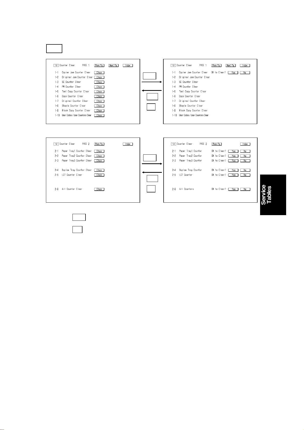
31 January 1996 SERVICE PROGRAM MODE
12 Counter Clear
Clear
YES
NO
A170M546.img A170M547.img
Clear
YES
NO
A170M548.img A170M549.img
1. Touch beside the count er you wish to clea r.
2. Touch to clear the counter.
Clear
Yes
4-33
Page 93

SERVICE PROGRAM MODE 31 January 1996
2.3 SP MODE INDEX
Index. Item
1-2 A3 Counter ON Mode 10 1 4-24
6-6 A3 Double count 10 6 4-36
1-5 Access Code 10 1 4-24
2-1 ADS 6 2 4-7
1-4 ADS Sensor 7 1 4-8
4-2 ADS Sensor Adjustment 9 4 4-17
1-5 ADS Sensor Test 8 1 4-10
2-6 All Counter Clear 12 2 4-33
3-6 Auto Drum Current Adjustment Mode 8 3 4-14
2-8 Block Copy Counter 3 2 4-5
1-9 Block Copy Counter clear 12 1 4-33
2-6 CFF Free Run Mode 8 2 4-13
2-3 CFF Original Counter 3 2 4-5
8-5 CFF Registration Adjustment 9 8 4-21
1-3 Charge Cleaner 8 1 4-12
3-1 Cleaning Blade OFF Mode 8 3 4-14
1-1 Copier Jam Counter Clear 12 1 4-33
1-1 Copier Operating Time 5 1 4-6
1-6 Copy Counter Clear 12 1 4-33
6-2 Copy Counter Up/Down Mode 10 6 4-30
5-4 Copy Disable Mode Set 10 5 4-29
6-1 Copy Number to Release Blade Pressure 10 6 4-30
7-3 Counter 6 7 4-7
1-1 Daily Copier Jam Counter 2 1 4-4
1-1 Daily Copy Counter 4 1 4-6
2-1 Daily Original Jam Counter 2 2 4-4
8-2 Daily SC Counter 6 8 4-7
6-4 Data Print I 10 6 4-30
6-5 Data Print II 10 6 4-30
3-1 Development 6 3 4-7
1-5 Development BIAS 7 1 4-8
3-1 Daily Peripheral Jam Counter 2 3 4-4
2-2 Drum Charge 6 2 4-7
2-1 Drum Conditioning Mode 8 2 4-13
2-3 Drum Potential 6 2 4-7
1-2 Drum Potential Sensor 7 1 4-8
1-6 Drum Potential Sensor Test 8 1 4-12
1-7 Drum Temperature 7 1 4-8
5-2 Duplex 6 5 4-7
2-7 Duplex Mode Copy Counter 3 2 4-5
SP Menu Manual
No. Page
Page
4-34
Page 94

31 January 1996 SERVICE PROGRAM MODE
Index. Item
2-4 Duplex Tray Counter Clear 12 2 4-33
6-7
1-1 Exposure 6 1 4-7
4-3 Exposure Lamp Adjustment 9 4 4-17
1-8 Exposure Lamp Heater Temperature 7 1 4-8
1-7 Exposure Lamp On Check 8 1 4-12
1-3 Exposure Sensor 7 1 4-8
4-2 Fan Motor 6 4 4-7
7-1 Finisher 6 7 4-7
4-1 Finisher Motor Test Mode 8 4 4-15
4-2 Finisher Free Run Mode 8 4 4-15
5-6 Focus Adjustment (200%) 9 5 4-18
5-5 Focus Adjustment (50%) 9 5 4-18
5-4 Focus Adjustment (Full Size) 9 5 4-18
2-3 Free Run Mode (Lamp OFF) 8 2 4-13
2-2 Free Run Mode (Lamp ON) 8 2 4-13
8-6 Front Staple Position Adjustment 9 8 4-21
6-1 Fusing 6 6 4-7
4-3 Fusing Idling Mode 10 4 4-28
1-1 Fusing Lower Temperature 10 1 4-24
2-7 Fusing Pressure Check Mode 8 2 4-13
1-6 Fusing Temperature 7 1 4-8
4-4 Fusing Temperature Adjustment 9 4 4-17
5-3 Horizontal Magnification Adjustment (200%) 9 5 4-18
5-2 Horizontal Magnification Adjustment (50%) 9 5 4-18
5-1 Horizontal Magnification Adjustment (Full Size) 9 5 4-18
4-6 ID Selection In ADS Mode 10 4 4-28
2-4 ID Sensor 6 2 4-7
1-1 ID Sensor 7 1 4-8
1-4 ID Sensor Test 8 1 4-12
3-2 Image Transfer 6 3 4-7
3-5 Jam Detection OFF Mode 8 3 4-14
10-1 Jogger Span Adjustment 9 10 4-23
11-1 Jogger Span Adjustment 9 11 4-23
4-5 Latent Image (Vd Vb Vl) Adj. 9 4 4-17
7-2 LCT 6 7 4-7
2-5 LCT Counter Clear 12 2 4-33
6-2 Leading Edge Erase Adjustment 9 6 4-19
6-1 Leading Edge Registration Adj. 9 6 4-19
1-3 Magnification 6 1 4-7
5-1 Magnification Ratio Priority 10 5 4-29
Enable Auto Reset function when key counter is
removed.
SP Menu Manual
No. Page
10 6 4-30
Page
4-35
Page 95

SERVICE PROGRAM MODE 31 January 1996
Index. Item
5-2 Manual ID Level Selection 10 5 4-29
2-1 No. of jams by location 1 2 4-3
1-2 No. of jams by paper size 1 1 4-3
1-7 Original Counter Clear 12 1 4-33
1-2 Original Jam Counter Clear 12 1 4-33
3-2 Original jams by location 1 3 4-3
5-1 Paper Feed 6 5 4-7
2-1 Paper Feed Time 7 2 4-9
9-1 Paper Feed Timing Adjustment 9 9 4-22
2-1 Paper Tray Copy Counter 3 2 4-5
2-1 Paper Tray1 Counter Clear 12 2 4-33
2-2 Paper Tray2 Counter Clear 12 2 4-33
2-3 Paper Tray3 Counter Clear 12 2 4-33
1-6 PM Alarm Enable 10 1 4-24
1-4 PM counter Clear 12 1 4-33
2-5 PM Cycle Copy Counter 3 2 4-5
1-1 Power Pack Output Adjustment 9 1 4-16
2-1 Power Pack Output Adjustment 9 2 4-16
3-1 Power Pack Output Adjustment 9 3 4-16
4-2 Process Control Auto Start Mode 10 4 4-28
3-2 Process Control Initial Setting 8 3 4-14
4-1 Process Control OFF Mode 10 4 4-28
6-3 RDH 6 6 4-7
2-5 RDH Free Run Mode 8 2 4-13
8-1 RDH Motor Adjustment 9 8 4-21
2-2 RDH Original counter 3 2 4-5
8-3 RDH Registration Adj. 9 8 4-21
8-7 Rear Staple Position Adjustment 9 8 4-21
7-1 ROM Part Number 10 7 4-32
1-3 SC Counter Clear 12 1 4-33
3-4 SC Detection OFF Mode 8 3 4-14
1-3 SC Telephone No. 10 1 4-24
1-2 Scanner 6 1 4-7
2-4 Scanner Free Run Mode 8 2 4-13
6-3 Scanner Motor Gain Adjustment 9 6 4-19
4-1 Se-Drum 6 4 4-7
2-1 Select Paper Size For Tray 10 2 4-26
5-3 Select Tray Display in APS Mode 10 5 4-29
1-1 Sensors 8 1 4-10
3-3 Separation 6 3 4-7
1-4 Serial No. 10 1 4-24
1-2 Solenoids/Clutches 8 1 4-11
SP Menu Manual
No. Page
Page
4-36
Page 96

31 January 1996 SERVICE PROGRAM MODE
Index. Item
1-8 Staple Counter Clear 12 1 4-33
1-5 Test Copy Counter Clear 12 1 4-33
5-5 Test Copy Counter ON 10 5 4-29
2-6 Test Mode Copy Counter 3 2 4-5
4-4 Toner Density Selection 10 4 4-28
3-3 Toner Forced Supply Mode 8 3 4-14
4-5 Toner Supply Amount 10 4 4-28
1-2 Total Copies by Paper Size 3 1 4-5
1-2 Total Copies by Paper Size 3 1 4-5
1-1 Total jams 1 1 4-3
2-9 Total No. of Staples 3 2 4-5
1-1 Total Number of Copies 3 1 4-5
1-1 Total Number of Copies 3 1 4-5
8-1 Total Number of SC 6 8 4-7
3-1 Total original jams 1 3 4-3
4-1
3-1 Tray Priority 10 3 4-27
1-10 User Codes/User Counters Clear 12 1 4-33
5-7 Vertical Magnification Adjustment 9 5 4-18
1-2 Weekly Copier Jam Counter 2 1 4-4
1-2 Weekly Copy Counter 4 1 4-6
2-2 Weekly Original Jam Counter 2 2 4-4
3-2 Weekly Peripheral Jam Counter 2 3 4-4
8-3 Weekly SC Counter 6 8 4-7
Transfer/Separation Corona ON Timing
Adjustment
SP Menu Manual
No. Page
9 4 4-17
Page
4-37
Page 97

DIP SWITCH TABLE 31 January 1996
3. DIP SWITCH TABLE
3.3 RDH MAIN CONTROL PCB
DIP 100
1234
ON OFF OFF ON Free Run (SW100 - Start/SW101 - Stop)
ON ON OFF ON Motor Test (use DIP101 to turn on)
ON ON OFF OFF Original incorrect positioning sensor check (*)
Function
Return DIPSW100 to the in itia l normal setting (DIP100-1, 2, 3, 4: of f) after
adjustment.
DIP101 Motor
1 Feed Motor
2 Belt Drive Motor
3 Inverter Motor
4 Blower Motor
3.4 RDH LEDs
LED No. Lights when the following sensor is activated.
100 Original set sensor
101 Separator HP sensor
102 Entrance sensor
103 1st transport sensor
104 2nd transport sensor
105 Registration sensor
106 1st inverter sensor
107 2nd inverter sensor
108 Exit sensor
109 Single feed set sensor
110 Single feed exit sensor
111 Inverter entrance sensor
112 Original length sensor
113 Separator sensor
114 Lift sensor
115 Inverter unit cover switch
(*)116 Motor speed – Middle
(*)117 Motor speed – High
(*)118 Motor speed – Low
120 Original height sensor
(*) In the original incorrect positioning sensor check mode (DIP100-1 , 2 on,
-3, 4 off), LED117 and 118 in red turn off and LED116 turns on in green.
4-38
Page 98

31 January 1996 PREVENTIVE MAINTENANCE SCHEDULE
4. PREVENTIVE MAINTENANCE SCHEDULE
4.1 PM TABLE
NOTE: The amounts mentioned in the PM interval are copy numbers.
C: Clean R: Replace L: Lubricate I: Inspect A: Adjustment
EM 150K 300K 450K 600K NOTE
OPTICS
Mirrors, Lens,
Reflector
1st and 2nd Scanner
Guides
Exposure Glass
CCCCC
Fiber Optics Cable
Exposure Flat Cable I I I I Replace at 3M
Exposure Lamp I I I I Replace at 900K
Optics Cooling Fan
Filter
Mirror Unit Guide Rod
Felt
Lens Horizontal Drive
Gear
Lens Guide Rod C C C C Dry cloth
PAPER FEED (for each paper feed station)
Pick-up Rollers RRRRCopy numbers are for each
Paper Feed Rollers RRRR
Separation Roller
Paper Feed Sensors C C C C Blower brush
Paper Feed Guides C C C C Dry cloth
Relay Rollers C C C C Water
Tray Drive Worm
Gears
Drive Gears
2nd Tray Drive Chain A Adjust the chain tension
Registration Roller C Water
Paper Dust Cleaning
Roller
Paper Dust Pan Replace at 1.2M
Transport Belt/Unit C C C C Water
AROUND THE DRUM
Drum C C C C Water/Dry cloth
Corona Wires RRRR
Wire Cleaner Pads RRRR
Toner Filter RRRR
L
L
L
L
CCCC
CCCC
CCCC
I, C I, C I, C I, C
RRRR
Soft cloth
Dry cloth
Water
Replace after 1M originals
feed
Dry cloth
Replace at 3M
Shake off any dust
Replace if necessary
Launa oil; if it’s dry
Mobil Temp 78; if lubrication is
necessary
paper feed station. Replace
the rollers as a set.
Mobil Temp 78; if lubrication is
necessary
Mobil Temp 78; if lubrication is
necessary
Replace at 1.2M
4-39
Page 99

PREVENTIVE MAINTENANCE SCHEDULE 31 January 1996
EM 150K 300K 450K 600K NOTE
Ozone Filter Replace at 1.2M
Corona Casing C C C C Water/Alcohol
Potential Sensor and
Drum Thermistor
Charge Corona Unit
Brush Seal
Erase Lamp C C C C Water
ID Sensor C C C C Water
QL Filter C C C C Water
Pick-off Pawls C C C C Alcohol
CLEANING UNIT
Cleaning Blade RRRRApply setting powder
Flick Blade RRRRApply setting powder
Cleaning Brush RRRR
Entrance Seal I, C I, C I, C I, C Blower brush
Side Seals
Cleaning Filter
Cleaning Unit Inside C C C C Remove toner
DEVELOPMENT UNIT
Developer RR
Upper Seal C C C C Blower brush
Side Seals I I I R
Toner Cartridge Seals I I I I Replace if necessary
Sleeve Drive Gears
Timing Belt Pulley C C C C Blower brush
Toner Near End
Sensor Feeler
Development Filter RRRR
Development Duct
Filter
FUSING UNIT
Hot Roller RR
Hot Roller Bushing I, L R I, L R Barrierta
Hot Roller Bearing I R I R
Pressure Roller R
Pressure Roller
Bushing
Pressure Roller
Bearing
Oil Supply Roller RRRR
Oil Supply Roller
Bushing
CCCC
CCCC
I, C I, C I, C I, C
I, C I, C I, C I, C
CCCR
IIII
RRRR
I, L I, L I, L R
IIIR
C C, R C C, R
Dry cloth/Blower brush
Blower brush
Blower brush;
Replace if damaged
Blower brush;
Replace if damaged
Blower brush;
Do not use any grease
Check movement
Barrierta
Suitable solvent
C: at 300K and 600K
(USA version)
R: at 300K and 600K
(European version)
4-40
Page 100

31 January 1996 PREVENTIVE MAINTENANCE SCHEDULE
EM 150K 300K 450K 600K NOTE
Stripper Pawls
Fusing Drive Gears L Mobil Temp 78
Guide Plates C C C C Suitable solvent
De-curling Belt C C C C Alcohol
De-curling Roller C C C C Suitable solvent
Fusing Transport
Rollers
Pressure Cleaning
Roller
Oil Supply Cleaning
Blade
Oil Supply Cleaning
Roller RRRR
DUPLEX (for duplex copies)
Pick-up Roller C C C C Clean with water
Paper Feed Roller RRRRReplace as a set
Separation Belts RRRR
Anti-static Brushes C C C C Blower brush
Positioning Roller I I I I
Positioning Roller Belt I I I I
Paper End Sensor C C C C Blower Brush
Timing Belt A A A A
Transport Rollers C C C C Clean with water
RDH (for originals)
Feed-in Belts C Alcohol
Transport Belt
Sensor Pads C C C C Blower brush
Feed and Transport
Rollers
Inverter and Exit
Rollers
Right Turn Rollers C Alcohol
FINISHER
Stapler I Replace after 200K staples
Rollers C A cloth dampened with alcohol
Sensors Clean at 1.5M copies with
Bushings
Antistatic Brush C Dry cloth
Brush rollers Replace at 1.5 M copies: 2
I, C I, C I, C I, C
CCCC
CCCC
RRRR
CCCR
L
Suitable solvent
Replace if damaged
Suitable solvent (Resin rollers)
Alcohol (Rubber rollers)
Suitable solvent
European version only
Replace the cleaning blade
and roller as a set.
(European version only)
Alcohol or belt cleaner
A0287464
Alcohol
C
Alcohol
C
Blower brush
Launa - 40 oil or equivalent; if
it make noise
large and 2 small rollers
4-41
 Loading...