

Page 1

IMPORTANT SAFETY NOTICES
PREVENTION OF PHYSICAL INJ URY
1. While the machine warms up, it will suddenly start turning to perform the
process control data initializa tio n. Keep hands away from any mechanical
and electrical components during this perio d.
2. Before disassembling or assembling parts of the copier and periph erals,
make sure that the copie r and the secon d sorter power cord is unplugged.
3. The wall outlet should be near the copie r and easily acce ssible .
4. Note that some comp onen ts of the copier, the paper tray un it, and the
2nd sorter are supplied with electrical volta ge even if the main switch is
turned off.
5. If any adjustment or operation check has to be made with exte rior cove rs
off or open while the main switch is turned on, keep hands away from
electrified or mechanically driven components.
6. The inside and the meta l pa rt s of the fusing unit become ext reme ly hot
while the copier is operating. Be careful to avoid touch ing tho se
components with your bare hands.
HEALTH SAFETY CONDITIONS
1. Never operate the copier without the ozone filte rs in sta lled.
2. Always replace the ozo ne filte rs wit h th e specified ones at the specified
intervals.
3. Toner and developer a re non-toxic, but if you get either of them in your
eyes by accident, it may cause tempo rary eye discomf ort. Try to remove
with eye drops or flush with water as f irst aid . If unsu ccessful, get medical
attention .
Page 2

OBSERVANCE OF ELECTRICAL SAFETY S TANDARDS
1. The copier and its peripherals must be inst alle d and main ta ine d by a
customer service represent at ive who has completed the training course
on those models.
2. The RAM board on the main contro l board ha s a lithium battery which can
explode if replaced incorrectly. Replace the battery only with an ide nt ical
one. The manufacture r recomme nd s replacing the entire RAM board. Do
not recharge or burn this battery. Used batteries must be handled in
accordance with local regulations.
SAFETY AND ECOLOGICAL NOTES FOR DI S POSAL
1. Do not incinerate the ton er cartridge or the used tone r. Ton er du st may
ignite suddenly when exposed to open flame.
2. Dispose of used toner, developer, and photoconductors according to local
regulations.
3. Dispose of replaced part s in accord an ce with local regulations.
4. When keeping used lithium batteries in order to disp ose of them later, do
not put more than 100 batteries per sealed box. Storing larger numb ers or
not sealing them apart may lead to chemica l re act ions and heat build-up.
Page 3

SECTION 1
OVERALL MACHINE
INFORMATION
Page 4

31 July 1995 SPECIFICATIONS
1. SPECIFICATIONS
Main Copier
Copier
Configuration: Console
Copy Process: Dry Electrostatic Transfer S yste m
Originals: Sheet/Book
Original Size: Maximum:
11" x 17", A3
420 x 700 mm (in moving-original scan mode,
Europe version only)
Copy Paper Size: Maximum:
1st and 2nd tray 11" x 17", A3
3rd tray 81/2" x 14", B4
By-pass table in moving-original scan mode
(Europe version only) 420 x 700 mm
Minimum:
Tray 51/2" x 81/2", A5
By-pass table in moving-original scan mode
(Europe version only) A5
Copy Paper Weight: Standard Copying: 14 ~ 42 lb, 52 ~ 157 g/m
Duplex Copying: 17 ~ 28 lb, 64 ~ 105 g/m
Tab Sheets: 90 lb index, 160 g/m
2
Warm Up Time: Within 8.0 minutes (room temp. 68°F, 20°C)
First Copy Time: 3.8 seconds (81/2" x 11", A4, copier only)
6.9 seconds (81/2" x 11", A4, with sorter stapler)
Copying Speed: 80 copies/minute (81/2" x 11")
82 copies/ minute (A4 )
Optional Equipment: 20 Bin Sorter 1 (A591)
20 Bin Sorter 2 (A591)
Large Capacity Tray (A592)
Key Counter Bracket Set (A59 8 - 00)
Key Counter (Procured loca lly)
Key Counter Holder (Procured loca lly)
Receiving Tray (spare part)
Guidance ROM Kit (A603)
2
2
1-1
Page 5

SPECIFICATIONS 31 July 1995
Reproduction Ratios: See the following table:
LT/DLT version A4/A3 version
200% 200%
Enlargement
Full Size 100% 100%
Reduction
155% 141%
129% 122%
121% 115%
93% 93%
77% 82%
74% 71%
65% 65%
50% 50%
Zoom: 50 ~ 200%
Copy Exit Tray Capacity: 250 Sheets
Toner Replenishment : Cartridge exchange (15 00 g)
Paper Feed: 1st tray (500 sheets)
2nd tray (500 sheets)
3rd tray (1,700 Sheets)
By-pass tray (40 sheets) (Europ ea n versio n)
Power Source: 240 V, 20 A or more (LT/DLT version)
220, 230, 240 V, 13 A or more (A4 /A 3 version)
Power Consumption:
LT/DLT version
Copier only Full system*
Warm up less than 2.10 kW less than 2.15 kW
Stand-by less than 0.50 kW less than 0.55 kW
Copying less than 2.50 kW less than 2.60 kW
Maximum less than 2.60 kW less than 2.70 kW
* Full system: Copier with document feeder, large capacity tray, and a sorter stapler.
A4/A3 version (at 230 V)
Copier only Full system*
Warm up less than 2.0 kW less than 2.05 kW
Stand-by less than 0.55 kW less than 0.6 kW
Copying less than 2.4 kW less than 2.5 kW
Maximum less than 2.5 kW less than 2.6 kW
* Full system: Copier with document feeder, large capacity tray, and a sorter stapler.
1-2
Page 6

31 July 1995 SPECIFICATIONS
Dimensions:
LT/DLT version
Width Depth Height
Copier with document feeder and copy tray 1,375 mm
54.2"
Copier with document feeder and one sorter
stapler
Copier with document feeder, large capacity
tray, and one sorter stapler
Copier with document feeder, large capacity
tray, and two sorter staplers
1,625 mm
64.0"
2,070 mm
81.5"
2,610 mm
102.8"
760 mm
30.0"
873 mm
34.4"
873 mm
34.4"
873 mm
34.4"
1,445 mm
56.9"
1,445 mm
56.9"
1,445 mm
56.9’
1,445 mm
56.9’
A4/A3 version
Width Depth Height
Copier with document feeder and copy tray 1,438 mm
56.7"
Copier with document feeder and one sorter
stapler
Copier with document feeder, large capacity
tray, and one sorter stapler
Copier with document feeder, large capacity
tray, and two sorter staplers
1,688 mm
66.5"
2,070 mm
81.5"
2,610 mm
102.8"
760 mm
30.0"
873 mm
34.4"
873 mm
34.4"
873 mm
34.4"
1,445 mm
56.9"
1,445 mm
56.9"
1,445 mm
56.9"
1,445 mm
56.9"
Weight:
Copier with document feeder 367 kg
Copier with document feeder and one sorter
stapler
Copier with document feeder, large capacity
tray, and one sorter stapler
Copier with document feeder, large capacity
tray, and two sorter staplers
LT\DLT version A4\A3 version
377 kg
809.1 lb
465 kg
1025.2 lb
506 kg
1115.6 lb
596 kg
1314. 0 lb
831.2 lb
475 kg
1047.2 lb
516 kg
1137.6 lb
616 kg
1358.1 lb
1-3
Page 7

SPECIFICATIONS 31 July 1995
Noise Emission:
Sound pressure level
(The measurements are made according to ISO 7779 at the operator position.)
Copier only Full system*
Stand-by less than 42 dB (A) less than 42 dB (A)
Copying
* Full system: Copier with document feeder, large capacity tray, and a sorter stapler.
less than 63 dB (A)
(average)
less than 64 dB (A)
(average)
Sound power level (The measurements are made according to ISO 7779.)
Copier only Full system*
Stand-by less than 58 dB (A) less than 62 dB (A)
Copying less than 74 dB (A) less than 78 dB (A)
* Full system: Copier with document feeder, large capacity tray, and a sorter stapler.
Document Feeder
Original Size:
Stack feed
mode
Maximum 11" x 17", A3 11" x 17", A3 11" x 17", A3 A2
Minimum 8
1/2" x 11", A4 51/2" x 81/2", A5 81/2" x 11", A4 B5
Single feed
mode
Duplex mode
Original Weight:
Stack feed
mode
Maximum 34 lb, 128 g/m
Minimum 14 lb, 52 g/m
Single feed
2
42 lb, 157 g/m
2
11 lb, 35 g/m
mode
Duplex mode
2
25 lb, 93 g/m
2
14 lb, 52 g/m
2
2
Feed-in Unit Capacity: 50 Shee ts (80 g/m2, 20 lb)
CFF Original Stack Height:Maximum: 50 mm
Original Set: First sheet on top, stack face down
Moving-Original
Scan
Moving-Original
Scan
93
52
1-4
Page 8

31 July 1995 SPECIFICATIONS
MEMO:
1-5
Page 9
COPY PROCESSES AROUND THE DRUM 31 July 1995
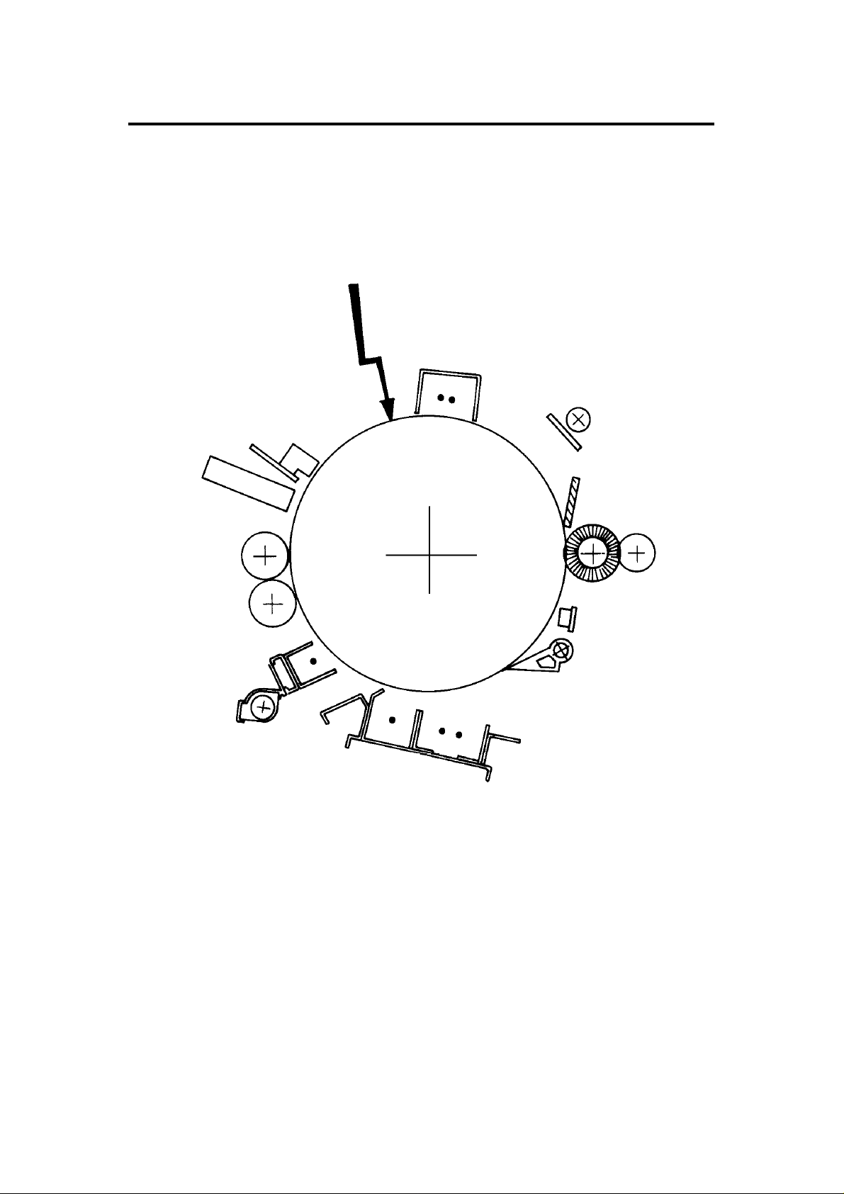
2. COPY PROCESSES AROUND THE DRUM
2
1
10
3
4
9
5
6
7
8
A171V513.img
1-6
Page 10

31 July 1995 COPY PROCESSES AROUND THE DRUM
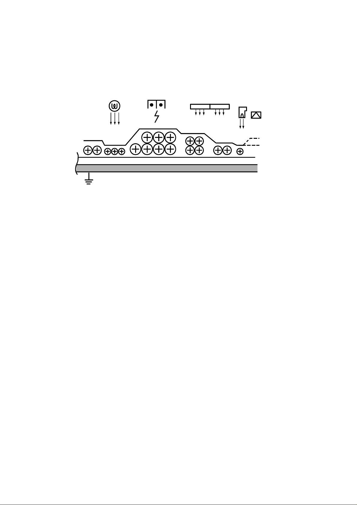
1. DRUM CHARGE
In the dark, the charge corona unit gives a uniform positive charge to the selenium drum.
The charge remains on the surface of the drum because the photo conductive selenium
has electrical resistance in the dark.
2. EXPOSURE
An image of the original is reflected to the selenium drum surface via the optics assembly.
The charge on the drum surface is dissipated in direct proportion to the intensity of the
reflected light, thus producing an electrical latent image on the drum surface.
3. ERASE
The erase lamp illuminates the areas of the charged drum surface that will not be used
for the copy image. The resistance of the drum in the illuminated areas drops and the
charge on those areas dissipates.
4. DRUM POTENTIAL SENSOR
The drum potential sensor detects the electric lines of force from the electric potential on
the drum to compensate image processing elements.
5. DEVELOPMENT
Negatively charged toner is attracted to the positively charged areas of the drum, thus
developing the latent image. (The negative triboelectric charge is caused by friction
between the carrier and toner particles.)
6. PRE-TRANSFER
The pre-transfer corona (PTC) applies a negative dc charge and an ac charge to the
drum. The dc charge increases the negative potential of the toner to improve toner
transfer to paper. The ac charge decreases positive charge on the drum and makes
paper separation easier. The pre-transfer lamp (PTL) also makes paper separation easier
by illuminating the drum and decreasing the positive charge on the drum.
7. IMAGE TRANSFER
Paper is fed to the drum surface at the proper time so as to align the copy paper and the
developed image on the drum surface. Then, a strong positive charge is applied to the
back side of the copy paper, providing an electrical force which causes the copy paper to
be attracted to the drum’s surface. At the same time, the toner particles are pulled to the
copy paper from the drum’s surface.
8. PAPER SEPARATION
A strong ac corona discharge is applied to the back side of the copy paper, reducing the
positive charge on the copy paper and breaking the electrical attraction between the
paper and the drum. Then, the stiffness of the copy paper causes it to separate from the
drum surface. The pick-off pawls help to separate paper which has low stiffness.
9. CLEANING
The cleaning brush first removes remaining toner on the drum surface. Then, the cleaning
blade which is angled against drum rotation (counter blade system) removes the rest of
the toner. The flick roller mechanically removes the toner on the cleaning brush.
10. QUENCHING
Light from the quenching lamp electrically neutralizes the drum surface.
1-7
Page 11
18192021222324
25
MECHANICAL COMPONENT LAYOUT 31 July 1995
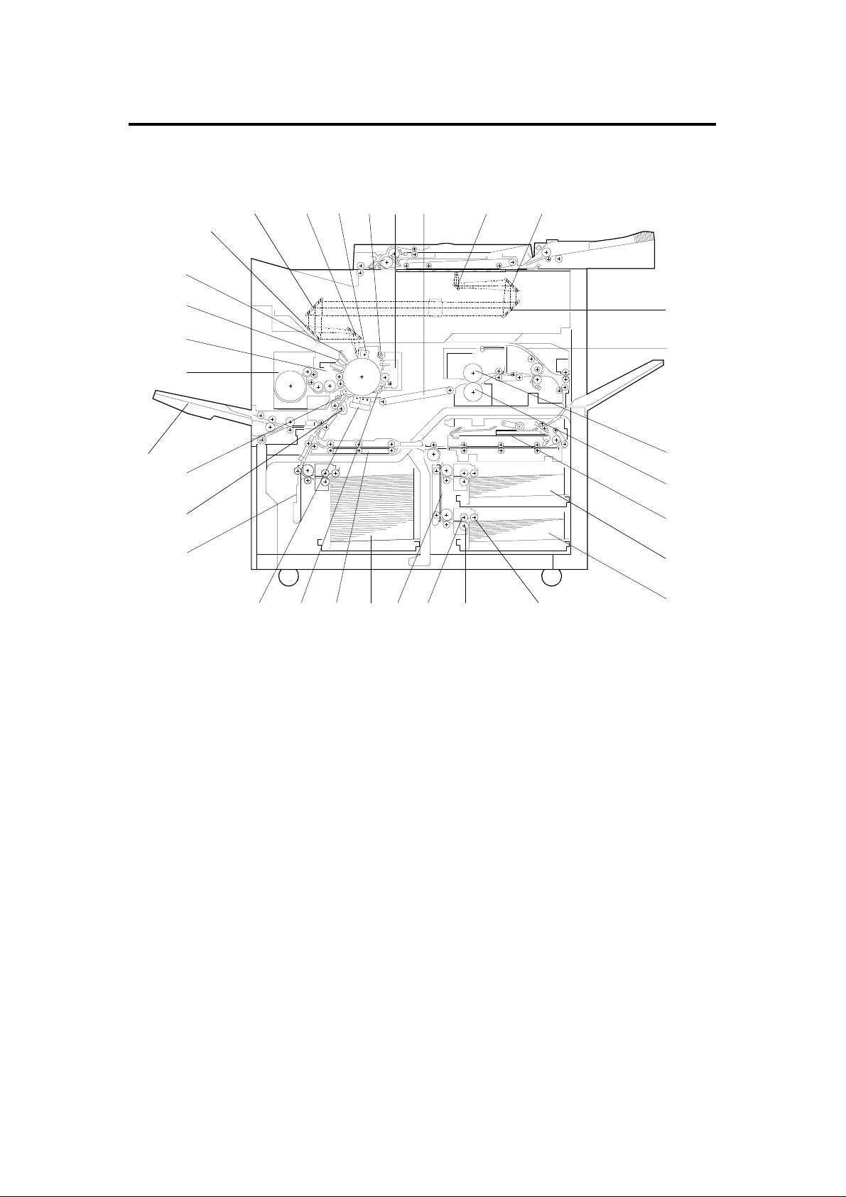
3. MECHANICAL COMPONENT LAYOUT
3.1 COPIER
26
27
302928 31
32
121314151617
1
11
2
3
4
5
6
7
8
9
10
A171V500.wmf
1. First Mirror
2. Second Mirror
3. Third Mirror
4. Inverter Guide Plates
5. Hot Roller
6. Pressure Roller
7. Duplex Tray
8. First Tray
9. Second Tray
10. Pick-up Roller
11. Separation Roller
12. Paper Feed Roller
13. Vertical Transport Unit-Right
14. Third Tray
15. Horizontal Transport Unit
16. Pick-off Pawls
17 Transfer and Separation
Corona Unit
18. Vertical Transport Unit-Left
19. Registration Rollers
20. Pre-transfer Corona Unit
21. By-pass Feed Table
(Europe version only)
22. Toner Hopper
23. Development Unit
24. Drum Thermistor and Drum
Potential Sensor
25. Erase Lamp
26. Fifth Mirror
27. Fourth Mirror
28. Sixth Mirror
29. Charge Corona Unit
30. Quenching Lamp
31. Cleaning Unit
32. Transport Unit
1-8
Page 12

31 July 1995 MECHANICAL COMPONENT LAYOUT
3.2 ARDF
12 34 5 6 7
1. Original Tray Extension
2. Upper Exit Rollers
10. 1st Pick-up Rollers
11. 2nd Pick-up Rollers
8
9
10
11
12131415161718
A171V509.img
3. Upper Inverter Gate
4. Lower Inverter Rollers
5. Upper Inverter Rollers
6. Switch Back Gate
7. Switch Back Tray
8. Upper Relay Roller
9. Friction Tab
12. Separation Rollers
13. Lower Relay Roller
14. Pressure Rollers
15. Transport Belt
16. Lower Inverter Gate
17. Lower Exit Rollers
18. CFF Guide
1-9
Page 13

ELECTRICAL COMPONENT DESCRIPTIONS 31 July 1995
4. ELECTRICAL COMPONENT DESCRIPTIONS
Refer to the electrical compon en t layo ut on the reverse side of the Point to
Point (Water proof paper) index numbers.
4.1 COPIER
Name Function Index. No.
Motors
1st Tray Drive Drives the bottom plate in the 1st tray. 64
2nd Tray Drive Drives the bottom plate in the 2nd tray. 65
3rd Tray Drive Drives the bottom plate in the 3rd tray. 71
Charge Wire Cleaner Drives the charge corona wire cleaner. 79
Development Drives the development unit. 50
End Fence Drive Drives the duplex end fence. 128
Fusing Cooling Fan Cools fins of the de-curling roller. 57
Fusing Exhaust Fan Removes the heat in the de-curling unit. 63
Jogger Fence Drive Drives the duplex jogger fences. 129
LCT Drive Drives the bottom plate in the LCT. 150
Lens Horizontal Drive Shifts the lens horizontal position. 55
Lens Vertical Drive Shifts the lens vertical position. 58
Main Drives the main unit components. 77
Mirror Unit Drive Positions the mirror unit. 84
Optics Cooling 1 Removes the heat from the optics unit. 82
Optics Cooling 2 Removes the heat from the optics unit. 81
Scanner Drive Drive the 1st and 2nd scanners. 56
T & S Wire Cleaner Drives the transfer and separation wire cleaner. 75
Toner Supply Rotates the toner supply roller. 78
Vacuum Fan Removes the heat and dust in the machine. 53
Clutches
LCT Drive Transmits the main copier drive to the LCT feed
section.
Left Vertical Transport
Unit Drive
Paper Feed - 1st Tray Drives the paper feed roller of the 1st tray. 67
Paper Feed - 2nd Tray Drives the paper feed roller of the 2nd tray. 66
Paper Feed - 3rd Tray Drives the paper feed roller of the 3rd tray. 76
Paper Feed - Duplex Drives the paper feed roller of the duplex unit. 130
Paper Feed - LCT Drives the paper feed roller of the LCT. 138
Right Vertical Transport
Unit Drive
Registration Drives the registration roller. 72
Paper Feed - By-pass Drives the paper feed roller of the by-pass feed table. 51
PCBs
DC Drive Drives dc components. 115
DC Motor Drive Drives the dc motors. 125
Transmits the main copier drive to the left vertical
transport unit and the 3rd trays.
Transmits the main copier drive to the right vertical
transport unit and the 1st and 2nd trays.
1-10
52
74
68
Page 14

31 July 1995 ELECTRICAL COMPONENT DESCRIPTIONS
Name Function Index. No.
Drum Current Detection Measures the corona current. 106
Main Controls overall machine operation. 121
Motor Control Controls the dc motors. 124
Operation Unit Controls the monitor display. 127
PTL Controls the pre-transfer lamp operation. 120
Quenching Lamp Controls the quenching lamp operation. 119
Interface Interface between the main PCB and other PCBs. 114
Vacuum Motor Controls the vacuum fan motor operation. 108
Power Packs
Charge Provides power for the charge corona wire. 103
Development Bias Provides power for the development bias. 104
PTC Provides power for the pre-transfer corona wire. 107
Separation Provides power for the separation corona wire. 105
Transfer Provides power for the transfer corona wire. 126
Power Supply Unit Provides dc power to dc components. 118
Relays
Anticondensation Heater Provides power to the anticondensation heater. 112
Drum Heater 1 Provides power to the drum heater. 113
Drum Heater 2 Provides power to the drum heater. 110
Fusing SSR Provides power to the fusing lamp. 111
Relay Unit Provides ac power to ac components. 117
Sensor
Auto Response Turns on the display from the screen saver condition. 93
By-pass Table Detects when the by-pass table is opened and
indicates the display on CRT screen.
Drum Potential Detects the drum surface voltage. 100
Duplex Entrance Detects misfeeds. 137
End Fence Home
Position
Exit Detects misfeeds. 10
Fusing Unit Detects misfeeds. 9
Image Density Measures the density of the image on the drum. 87
Jogger Home Position Detects when the duplex side plate is at the home
Lens Horizontal Encoder Detects the lens horizontal drive motor operation. 5
Lens Horizontal Home
Position
Lens Vertical Encoder Detects the lens vertical drive motor operation. 7
Lens Vertical Home
Position
Lower Limit - 1st Tray Turns off the 1st tray motor when the tray reaches the
Lower Limit - 2nd Tray Turns off the 2nd tray motor when the tray reaches
Detects when the duplex end fence is at the home
position
position.
Detects when the lens is at the horizontal home
position.
Detects when the lens is at the vertical home position.
down position.
the down position.
34
136
131
4
6
48A
48B
1-11
Page 15

ELECTRICAL COMPONENT DESCRIPTIONS 31 July 1995
Name Function Index. No.
Lower Limit - 3rd Tray Turns off the 3rd tray motor when the tray reaches
the down position.
Lower Limit - LCT Turns off the LCT motor when the tray reaches the
down position.
Mirror Unit Encoder Detects the mirror drive motor operation. 37
Mirror Unit Home
Position
Paper End - 1st Tray Detects the presence of paper in the 1st tray. 49A
Paper End - 2nd Tray Detects the presence of paper in the 2nd tray. 49B
Paper End - 3rd Tray Detects the presence of paper in the 3rd tray. 49C
Paper End - By-pass
Table
Paper End - Duplex Detects the presence of paper in the duplex tray. 132
Paper End - LCT Detects the presence of paper in the LCT. 141
Paper Feed - 1st Tray Turn off the 1st tray paper feed clutch. 15
Paper Feed - 2nd Tray Turn off the 2nd tray paper feed clutch. 14
Paper Feed - 3rd Tray Turns off the 3rd tray paper feed clutch. 20
Paper Feed - Duplex Turns off the duplex paper feed clutch. 133
Paper Feed - LCT Turn off the LCT paper feed clutch. 153
Paper Feed - By-pass Turn off the by-pass paper feed clutch. 36
Paper Size 1 - 1st Tray Determines what paper size is in the 1st tray. 42A
Paper Size 1 - 2nd Tray Determines what paper size is in the 2nd tray. 42B
Paper Size 1 - By-pass
Feed
Paper Size 1 - LCT Determines what paper size is in the LCT. 142
Paper Size 2 - 1st Tray Determines what paper size is in the 1st tray. 41A
Paper Size 2 - 2nd Tray Determines what paper size is in the 2nd tray. 41B
Paper Size 2 - By-pass
Feed
Paper Size 2 - LCT Determines what paper size is in the LCT. 143
Paper Size 3 - 1st Tray Determines what paper size is in the 1st tray. 40A
Paper Size 3 - 2nd Tray Determines what paper size is in the 2nd tray. 40B
Paper Size 3 - By-pass
Feed
Paper Size 3 - LCT Determines what paper size is in the LCT. 144
Paper Size 4 - 1st Tray Determines what paper size is in the 1st tray. 39A
Paper Size 4 - 2nd Tray Determines what paper size is in the 2nd tray. 39B
Paper Size 4 - By-pass
Feed
Paper Size 5 - 1st Tray Determines what paper size is in the 1st tray. 46A
Paper Size 5 - 2nd Tray Determines what paper size is in the 2nd tray. 46B
Paper Size 6 - 1st Tray Determines what paper size is in the 1st tray. 45A
Paper Size 6 - 2nd Tray Determines what paper size is in the 2nd tray. 45B
Paper Size 7 - 1st Tray Determines what paper size is in the 1st tray. 44A
Paper Size 7 - 2nd Tray Determines what paper size is in the 2nd tray. 44B
Paper Size 8 - 1st Tray Determines what paper size is in the 1st tray. 43A
Paper Size 8 - 2nd Tray Determines what paper size is in the 2nd tray. 43B
Detects when the mirror unit is at the home position.
Detects the presence of paper in the by-pass table.
Determines what paper size is in the by-pass feed
tray. (European version only)
Determines what paper size is in the by-pass feed
tray. (European version only)
Determines what paper size is in the by-pass feed
tray. (European version only)
Determines what paper size is in the by-pass feed
tray. (European version only)
48C
146
3
32
30
29
28
27
1-12
Page 16

31 July 1995 ELECTRICAL COMPONENT DESCRIPTIONS
Name Function Index. No.
Paper Volume - 1st Tray Detects the amount of paper in the 1st tray. 38A
Paper Volume - 2nd Tray Detects the amount of paper in the 2nd tray. 38B
Paper Volume - 3rd Tray Detects the amount of paper in the 3rd tray. 38C
Paper Volume - LCT Detects the amount of paper in the LCT. 148
Registration Sensor Detects the lead edge of paper to determine the stop
timing of a feed clutch and detects misfeeds.
Return Home Position Detects when the 1st scanner is at the return position. 31
Scanner Home Position Detects when the 1st scanner is at the home position. 8
Sheet Through Home
Position
Toner Cartridge Detects when a toner cartridge is in the machine. 2
Toner Coil Overload Detects the toner collection coil drive gear operation. 1
Toner Near End Detects toner near end condition. 35
Transport Detects misfeeds. 18
LCT Paper Position Detects the top sheet position in the LCT tray. 140
Upper Limit - 1st Tray Sends signal to stop lifting up the 1st tray bottom
Upper Limit - 2nd Tray Sends signal to stop lifting up the 2nd tray bottom
Upper Limit - 3rd Tray Sends signal to stop lifting up the 3rd tray bottom
Upper Limit - LCT Sends signal to stop lifting up the LCT bottom plate. 151
Duplex Exit Jam detector. 16
Detects when the 1st scanner is at the 1 sheet
through home position. (European version only)
plate.
plate.
plate.
22
33
12
13
19
Solenoids
Cleaning Brings the cleaning blade into contact with the drum. 54
Inverter Gate Drives the inverter gate up and down. 62
Junction Gate Drives the junction gate up and down. 61
LCT Lock Locks the LCT. 139
Pick-up - 1st Tray Lifts the pick-up roller of the 1st tray. 69
Pick-up - 2nd Tray Lifts the pick-up roller of the 2nd tray. 70
Pick-up - 3rd Tray Lifts the pick-up roller of the 3rd tray. 73
Pick-up - LCT Lifts the pick-up roller of the LCT. 149
Pick-up - By-pass Lifts the pick-up roller of the by-pass feed table. 83
Pinch Roller Brings the return pinch rollers into contact with a
paper.
Duplex Pressure Plate Brings the pressure plate on papers in the duplex unit. 134
Positioning Lowers the positioning roller in the duplex unit. 135
Original Scale Moves the original scale to the sheet through position
(European version only).
By-pass Gate Moves the by-pass gate to the down position. 80
Switches
1st Tray Down Lowers the 1st tray bottom plate. 47A
2nd Tray Down Lowers the 2nd tray bottom plate. 47B
3rd Tray Down Lowers the 3rd tray bottom plate. 47C
LCT Down Lowers the LCT bottom plate. 147
60
59
1-13
Page 17

ELECTRICAL COMPONENT DESCRIPTIONS 31 July 1995
Name Function Index. No.
Anticondensation Turns on the tray heaters. 23
Error Reset Resets error condition. 11
LCT Cover Turns off components when the LCT top cover is
open.
Left Door 1 Turns off the main motor when the left door is open. 25
Left Door 2 Turns off dc 24 volts lines when the left door is open. 24
Main Supplies power to the copier. 26
Right Door 1 Turns off dc 24 volts lines when the right door is open. 21
Right Door 2 Turns off the main motor when the right door is open. 17
Heaters
1st Tray Removes humidity from the paper in the 1st tray. 91
2nd Tray Removes humidity from the paper in the 2nd tray. 92
3rd Tray Removes humidity from the paper in the 3rd tray. 94
Anticondensation Prevents moisture from forming on the lens and
mirrors.
Drum Warms the drum when it gets too cool. 95
Exposure Lamp Warms the exposure lamp when it gets too cool. 86
LCT Removes humidity from the paper in the LCT. 145
152
101
Lamps
Exposure Exposes the original with high intensity light. 85
Fusing Provides heat to the hot roller and keeps the roller at
the operating temperature.
Pre-Transfer Removes excessive positive charge from the drum
surface to the transfer and separation process.
Quenching Electrically neutralizes the drum surface prior to
charging.
Eraser Discharges the drum outside the image area.
Provides lead/trail edge erase.
Thermistors
Drum Monitors the drum temperature. 99
Fusing Monitors the hot roller temperature. 88
Other Components
Total Counter Keeps a count of the number of copies made. 116
FL Stabilizer Stabilizes power to the exposure lamp. 109
Thermofuse Provides back-up overheat protection in the fusing
unit.
Anticondensation
Thermoswitch
Turns off the anticondensation and drum heaters.
89
98
97
96
90
102
1-14
Page 18

31 July 1995 ELECTRICAL COMPONENT DESCRIPTIONS
4.2 ARDF
Symbol Name Function Index. No.
Motors
M1
M2 Belt Drives the transport belt. 16
M3 Inverter Drives the inverter rollers and the exit rollers. 17
M4 Job Separation Drives the job separator. 5
Circuit Boards
PCB1 DF Main Controls overall ARDF functions. 3
PCB2
Solenoids
SOL1
SOL2 Inverter Gate Opens the inverter gate. 23
SOL3
SOL4
Feed-in Drives the pick-up rollers, separation rollers
and relay rollers.
Indicator Indicates the Insert Original indicator and the
Auto Feed indicator.
Switch Back Switches the switch back gate position to
directs the original to the switch back tray or
onto the exposure glass.
Moving Original
Scan Gate
Sheet-through
Guide
Opens the moving original scan gate
(European version only).
Moves the sheet-through guide to the sheet
through position (European version only).
2
6
15
25
27
Sensors
S1 Entrance Cover Detects if the entrance cover is open. 4
S2 Lift Detects if the transport unit is open. 14
S3 Inverter Cover Detects if the inverter cover is open. 22
S4
S5
S6
S7
S8
S9 Inverter Jam Detects paper jams in switch back operation. 18
S10
S11
S12 Exit Detects paper jams. 21
S13
Pick-up Roller
H.P.
Job Separation
H.P.
Job Completion Detects that last original of the first job is fed
Original Detects if the original is set on the original
Registration Sets the feed-in motor, belt motor and inverter
Inverter
Registration
Inverter Entrance Sets the inverter motor and the belt motor off,
CFF Detects if the computer form is set in the CFF
Detects if the pick-up roller is in the home
position.
Detects if the job separator is in the home
position.
from the original table.
table.
motor off timing. Detects original misfeed.
Sets the inverter motor and the belt motor off,
reversing timing. Detects original jams.
reversing timing, inverter solenoid and switch
back solenoid off timing.
guide. Counts the holes lined up on the
computer form.
1
7
8
9
12
19
20
11
1-15
Page 19

ELECTRICAL COMPONENT DESCRIPTIONS 31 July 1995
S14 Original Width Detects the original width. 13
S15 Timing Supplies timing pulses to the DF main board. 10
S16
Others
Oth1
Oth2
Moving Original
Scan Entrance
CFF Guide Switch Detects whether the CFF guide is in the rear
Sheet Feed
Clutch
Detects when the original is set on the moving
original scan entrance (European version only).
end position or not (European version only).
Drives the sheet feed rollers (European
version only).
24
26
28
1-16
Page 20
A
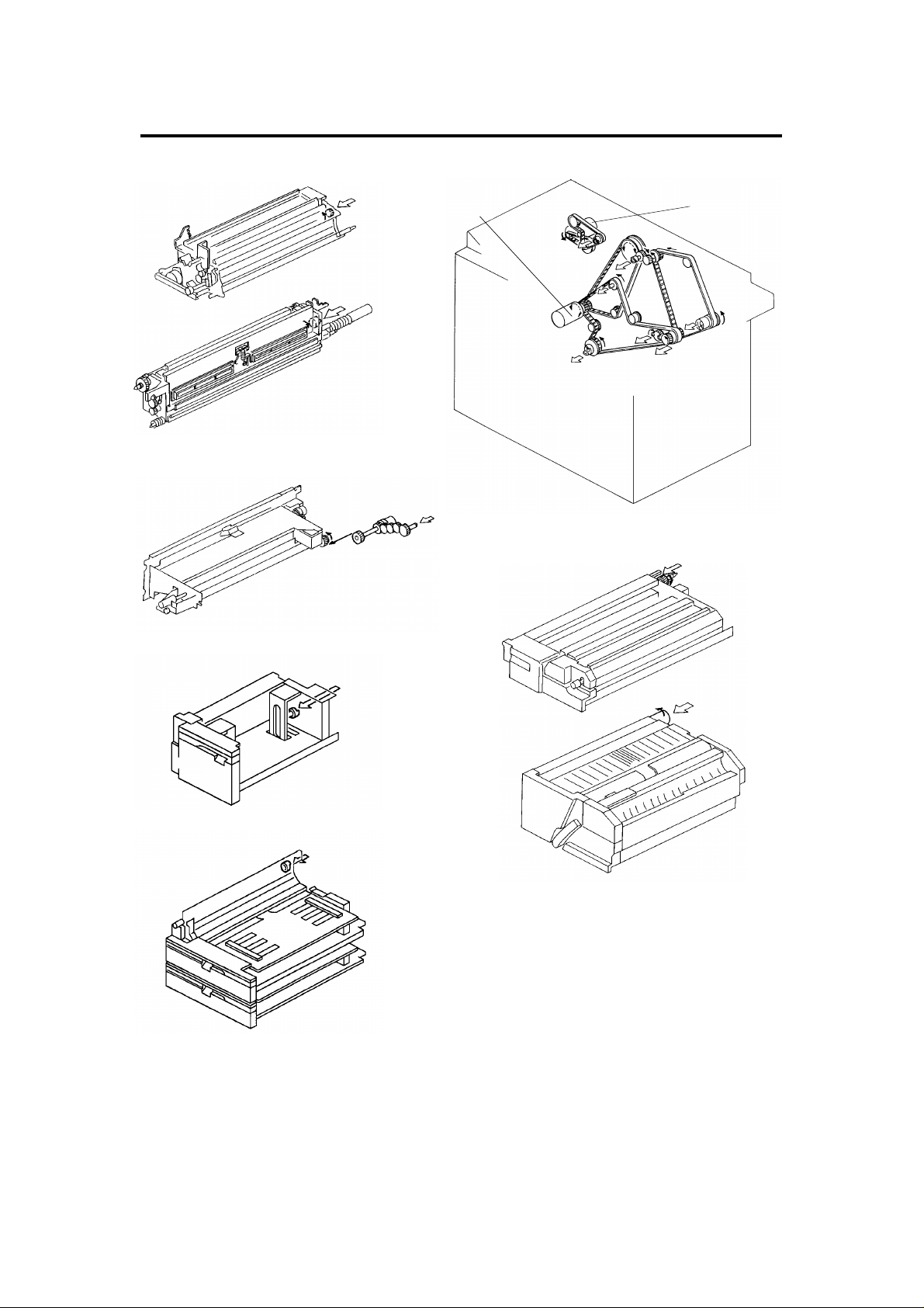
31 July 1995 DRIVE LAYOUT
5. DRIVE LAYOUT
A
B
A171V510.img
A171V511.img
C
1
B
C
2
D
E
G
F
A171V508.img
F
G
A171V506.img
E
A171V507.img
1. Main Motor
2. Development Drive Motor
D
A171V512.img
A : Development Unit
B : Cleaning Unit
C : Relay Transport Unit
(to LCT & By-pass Table)
D : Fusing Unit
E : Vertical Transport Unit-Right
F : Duplex Unit
G: Vertical Transport Unit-Lef t
1-17
Page 21
PAPER PATH 31 July 1995
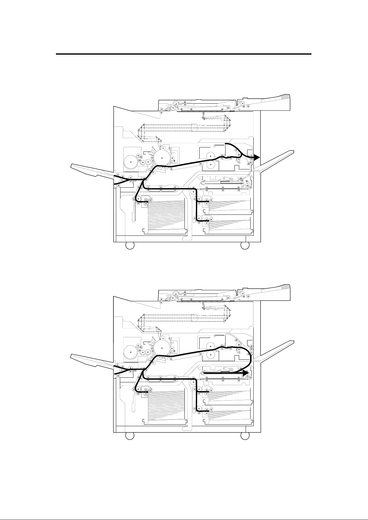
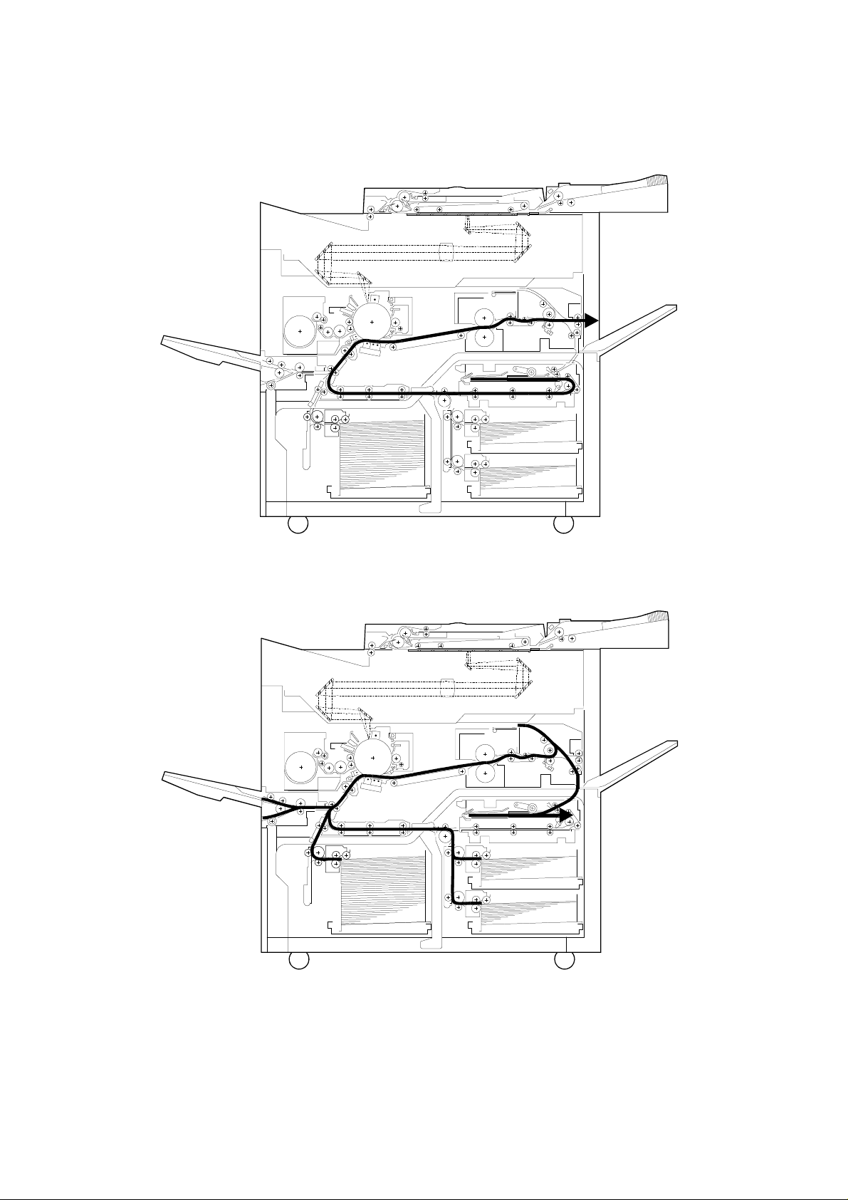
6. PAPER PATH
6.1 SINGLE SIDED COPY – COPY FACE DOWN
6.2 DUPLEX MODE (1ST SIDE)
A171V501.wmf
1-18
A171V502.wmf
Page 22
31 July 1995 PAPER PATH
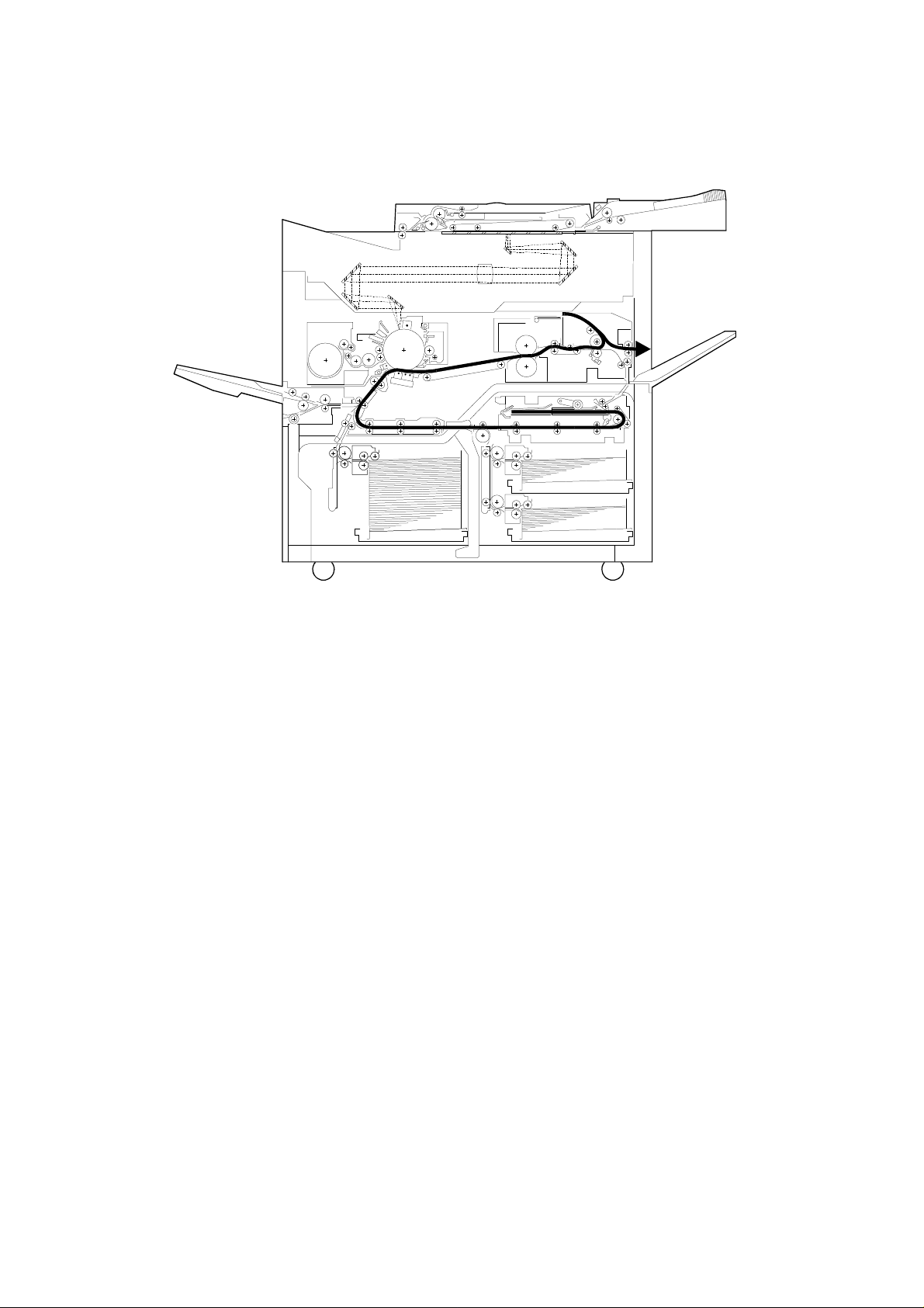
6.3 DUPLEX MODE (2ND SIDE)
6.4 IMAGE OVERLAY MODE (1 ST SIDE)
A171V503.wmf
1-19
A171V504.wmf
Page 23
PAPER PATH 31 July 1995
6.5 IMAGE OVERLAY MODE (2ND SIDE )
A171V505.wmf
1-20
Page 24

SECTION 2
DETAILED SECTION
DESCRIPTIONS
Page 25

Drum Current
Detection PCB
31 July 1995 PROCESS CONTROL
1. PROCESS CONTROL
1.1 OVERVIEW
The characteristics of each unit which is relat ed to the cop y ima ge
reproduction are changed by various factors. To get stable images over long
periods and in continuous copy run s, th ese chara cteristic changes have to be
compensated.
The following figure and table show how these facto rs are compensated on
this copier.
Potential Sensor
Toner
Supply
Development
Bias
Exposure Lamp
PTC
Main PCB
Transfer
Corona
Charge Corona
ID Sensor
Separation
Corona
: Sensing Item
: Controlled Item
A171D522.wmf
2-1
Page 26

PROCESS CONTROL 31 July 1995
Section Characteristics Causes of Change Compensation Method
Drum Charge Potential Repeat Stress
Temperature
Humidity
Sensitivity Repeat Stress
Temperature
Humidity
Residual
Voltage
Charge
Corona
Exposure Lamp Intensity Repeat Stress Measure the drum potential of a part
Development Amount of
Charge Potential Dirtiness
Mirror
Reflectivity
Lens Clearness
Toner Charge
Repeat Stress
Temperature
Humidity
Temperature
Humidity
Dirtiness
Repeat Stress
Temperature
Humidity
Measure the drum potential of a part
that was not exposed (Dark Potential)
with the potential sensor and adjust
the charge corona output.
Measure the drum potential of a part
that was exposed (Light Potential)
and adjust the exposure lamp voltage.
Measure the drum potential of a part
that was erased by the erase lamp
(residual voltage) and adjust the
development bias, light potential, and
dark potential
Measure the drum potential of a part
that was not exposed (dark potential)
and adjust the charge corona output.
that was exposed (light potential) and
adjust the exposure lamp voltage.
Measure the reflected light intensity of
the ID sensor pattern and adjust the
toner density in the development unit.
2-2
Page 27
Vd
VL
31 July 1995 PROCESS CONTROL
1.2 IMAGE CONTROL
1.2.1 Latent Image Control
QL
Charge
0
V
Exposure
Black White
Erase
Potential
Sensor
Vr
Drum
A171D507.wmf
The figure shows the change s of the drum potential durin g the copy process.
V0: The drum potentia l just af te r charging the drum.
Vd (Dark Potential): The drum potential just after exposing the black
pattern (Vd pattern)
VL (Light Potential): The drum potential just after exposing the white
pattern (VL pattern)
Vr (Residual Voltage): The drum potential just after t he expo sure of the
erase lamp.
2-3
Page 28

Vr
PROCESS CONTROL 31 July 1995
V0
Vd
Drum
Potential
V
L
LightOriginal DensityDark
A171D519.wmf
The above figure shows the relatio nsh ip be twe en the drum pote nt ial and th e
original density (exposing ligh t intensity). To get constant copy quality, this
relationship must be maintained.
Since this relationship tends to change to the one rep resented by the dotted
line by various factors, compensations are required as follows:
A decrease in dark voltage (Vd) is compensated for by increasing the charge
corona output. A increase in light voltage (VL) is compensated for by
increasing the exposu re lamp voltage. Since the resid ual vo lta ge (V r )
increase cannot be compen sat ed for by increasing the lamp voltage , it is
compensated by increasing the development bias voltage and changing the
Vd and VL standard value.
1.2.2 Image Density Control
To maintain constant copy image density, the ID sensor dete cts the toner
amount of the ID sensor pattern. From this, it is understood that drum
potential is stabilized with the above compe nsa tions. According to the
detection results, the ton er density in the development unit is controlled so
that the toner amount on the sensor pattern is constant.
The following sections explain the details of these compensations.
2-4
Page 29

31 July 1995 PROCESS CONTROL
1.3 PROCESS CONTROL DATA INITIALIZATIO N
The following flow chart shows all t he st eps tha t will be performed whenever
the main switch is turned on while the hot roller temperature is below 100°C.
This initializes all the process control set tings.
Main SW On (Fusing Temp. < 100°C)
Drum Potential Sensor Calibration (Fusing Temp . = 160°C)
Drum Conditioning Start (Fusing Temp . = 160 ° C)
• Exposure lamp ON
Vsg Adjustment
Lamp Intensity Sensor Calibration
Charge Corona Current Adjustment
Vr Measurement
• Lens position shift
• Exposure lamp OFF
• Scanner moves to return position (Vd Pattern)
• Exposure lamp ON
Vd Correction
• Exposure lamp OFF
• Scanner returns to home position (VL Pattern)
• Exposure lamp ON
VL1 Correction
• Exposure lamp OFF
V01 Detection
• Scanner moves to re tu rn po sitio n (ADS Pat te rn)
• Exposure lamp ON
ADS Adjustment
2-5
Page 30

TRIG 1 (800V)
TRIG 2 (100V)
PWM
Sensor
PROCESS CONTROL 31 July 1995
1.3.1 Drum Potential Sensor Calibration
[A]
A171D585.img
Potential Sensor
Bias
P.P.
Case
Sensor
Output
Amp.
Drum
A171D512.wmf
RA2
RA1
Drum Current
Detection PCB
Relay
Main PCB
A171D511.wmf
The drum potential sensor [A] is locat ed just ab ove the deve lop men t un it. The
sensor has a detector which detect s the elect ric lin es of force from the
electric potential on the drum. The output of th e sensor de pe nds of th e
number of electric lines of force.
Since the output of the sensor is affected by enviro nme nt al conditions, such
as temperature and humidity, the sensor output is calibrated du ring proce ss
control data initialization.
The drum current detection board ha s two rela y contacts. Usually RA2
grounds the drum. However, during the initialization, the main PCB turns RA1
on and RA2 off and applies the deve lopment bias to the drum shaft.
By measuring the outputs of the drum potentia l sensor when +100 V and
+800V are applied to the drum, the sensor output is calibra ted auto mat ically.
2-6
Page 31

31 July 1995 PROCESS CONTROL
1.3.2 Drum Conditioning
When the fusing temp erature reaches 160°C, th e mach ine starts the drum
conditioning proce ss. In this mode, all the coronas and lamps around the
drum are activated and drum sensitivit y is sta bilize d, as in cont inu ou s copy
runs.
1.3.3 Vsg Adjustment
During drum conditioning, the ID sensor checks th e bare dru m’s reflectivity
and calibrates the ou tp ut of the ID sensor to +4 V.
1.3.4 Lamp Intensity Sensor Calibration
Main PCB
PWM
FL
Stabilizer
A171D569.img
The exposure lamp intensity is monit ored by the main PCB through the fibe r
optics cable. A photodiode on the main PCB con vert s the light inte nsity to a
dc voltage. The main PCB sen ds a PWM sign al with a 100% duty cycle to the
FL stabilizer and checks the monitored voltage, adjusting it to +3 V. This +3 V
is used as the light intensity standard.
2-7
Page 32

MainPCB
Potential S.
PROCESS CONTROL 31 July 1995
1.3.5 Charge Corona Current Adjustment
Id Set
Drum Current Detect PCB
A11D502.wmf
The charge corona current is measu red and adju ste d au to mat ically by the
drum current detect PCB.
The charge corona current flows to the drum current dete ct PCB through the
drum and the drum shaft. The drum sha ft is gro unde d by the dru m current
detect PCB usually. However, during the process control data initialization,
the main PCB activates the corona current circuit in the drum current
detection PCB which converts the drum curre nt to a voltag e and sep ara te s it
into ac and dc component outputs. Then, the main PCB read s the m t hro ug h
A/D converters as digital da ta. The main PCB adjusts the coro na current by
controlling the PWM signal to the charge corona power pack.
When the auto drum current adjustment mode is selected by th e SP mode,
the drum current dete ct PCB is used to measure and adjust oth er corona
outputs in the same way.
2-8
Page 33

31 July 1995 PROCESS CONTROL
1.3.6 Vr Measurement
0
V
Vd
Drum
Potential
L
V
Vr
Dark
Original Density
Light
A171D510.wmf
The drum residual voltage (Vr) tends to in crea se du ring the drums life due to
electrical fatigue. The resid ual vo lta ge cannot be red uce d eve n if the
exposure lamp voltage is increase d. Therefore, the Vr chan ge has to be
compensated by other means.
The main PCB checks the drum pot en tial just after the erase lamp exposure,
by the drum potential se nso r d urin g drum conditioning. The dru m pot en tia l is
in fact Vr. This measured Vr is used as the sta ndard for the following other
compensations.
1. Vd Correction
2. VL1 Correction
2-9
Page 34

Original Density
PROCESS CONTROL 31 July 1995
1.3.7 Vd Corr ection
Vd
Drum
Potential
Exposure
Glass
Vr
Vd Pattern
Dark
Light
A171D508.wmf
A171D520.wmf
The drum potential just after the bla ck pat te rn (Vd Pat te rn) is expo sed (Vd:
Dark Potential) tends to lowe r d urin g drum life due to a decrease in the
drum’s capacity to carry a charge.
To check the actual Vd, the first scanner moves to the return posit ion and the
Vd pattern (Black) stuck on the bottom side of the exposure glass bracket is
exposed on the drum.
The main PCB measures Vd thro ug h the drum potential senso r and adju st it
to a target value by adjusting the charge power pack output.
On the other hand, there is a change of the drum resid ua l voltage (Vr), so
that the target Vd voltage is compensated as follows:
Target Vd Value: Vd = Vr + 770 V - 20 M
NOTE: M is the sett ing for the Latent Image Adj. in the SP mode.
The adjusted charge powe r pack ou tput control value (PWM value) is kept in
memory until the next initialization.
If the target value cann ot be ach ieve d within the charge power pack ou tp ut
control range, the copie r indica tes the system error on the CRT screen. The
copier tries the Vd check again af ter the error reset. Even if the secon d Vd
adjustment fails, no SC condition is displayed. The previous power pack
output control data will be used in this case.
2-10
Page 35

Original Density
31 July 1995 PROCESS CONTROL
1.3.8 VL Corr ection
VL Pattern
Drum
V
L
Vr
Light
A171D521.wmf
A171D508.wmf
Potential
Dark
Dirty optics and/or exposure lamp det erio ration decreases the intensit y of th e
light that reaches the drum. In additio n to this, the drum sen sitivit y also
changes during the drum’s life. These fa ctors change the drum potential just
after white pattern exposure (VL: Light Potential).
To check the actual VL, the first scanner moves to the home position and the
VL pattern (White) stuck on the bottom side of the exposure glass bracket is
exposed on the drum.
The main PCB measures the VL through the drum potential sen sor an d
adjusts it to a target value by ad justing the exposure lamp output.
The residual voltage cha ng e also aff ects VL, so that V L ’s target voltage is
compensated as follows:
Target Value of VL: VL1 = Vr + 50 – 10 N -15 M (volt)
NOTE: N is the setting fo r th e exposure lamp adjustment in the SP mod e.
M is the setting for th e Latent Image Ad j. in th e SP mode.
The adjusted exposure lamp out pu t con tro l value (PWM value) is kept in
memory until the next initialization.
If the target value cann ot be ach ieve d within the exposure lamp out pu t
control range, the copie r indica tes the system error on the CRT screen. The
copier tries the VL check again after the SC reset. Even if the secon d VL
adjustment fails, no SC condition is displa yed. The previous exposure lamp
output control data will be used in this case.
2-11
Page 36

Light
PROCESS CONTROL 31 July 1995
1.3.9 V01 Measuring
V0
Vd
Drum
Potential
Dark
Original Density
A171D513.wmf
Since the ID sensor pattern on the drum is made by the erase lamp and
charge corona (except for B4 /81/2" x 14" copy mode due to the len s horizo ntal
movement. See toner density detection and supply section for details), the
sensor pattern density varies with drum potential just after the charg e coro na
(V0) is applied.
To measure the toner density prop erly, the deve lop men t bias for the ID
sensor pattern is corrected by mea surin g th e actua l drum po te nt ial afte r t he
charge corona.
During the process control data initializatio n, the drum pote ntial af te r the
charge corona is applied when the drum sensitivit y is stabilize d (V 01) will be
measured and used to det ermine the bias voltage for th e ID sensor pattern
development in continu ou s copy run . The details will be explained in the
toner density detectio n sect ion.
2-12
Page 37

Exposure Glass
31 July 1995 PROCESS CONTROL
1.3.10 ADS Adjustment
ADS Pattern
ADS Pattern
A171D508.wmf
A171D570.img
The ADS pattern is locate d un derneath the exposure gla ss bracke t. During
the process control data initializa tion, the ADS reference voltage is adjust ed .
When the first scanner is moved to the return posit ion for the Vd adjustment,
the main PCB checks the ADS voltage throu gh the ADS fib er op tics cab le.
The measured voltage is calibrat ed to th e sta nd ard voltage (3 V) as the
reference for the auto image density control.
2-13
Page 38

Original Density
VL
PROCESS CONTROL 31 July 1995
1.4 COMPENSATIONS DURING COPY CYCLE
During continuous copying , th e drum sensitivity changes due to the elect rical
fatigue. The drum sensitivity also changes during rest time.
The following compensations are used for the drum sensitivity cha nges in th e
copy cycle:
VL Pattern
V0
Vd
VBB
Drum
Potential
Vr
A171D508.wmf
Dark
Light
A171D510.wmf
1.4.1 VL Compe nsa tion
The drum light potential (VL) is changed du ring the copy cycle.
To get constant image qua lity in con tinuous copy runs, the develop ment base
bias is compensated during the copy cycle.
At the beginning of each original scanning, the VL sensor pattern is
developed on the drum. The main PCB mon ito rs t he drum potential (VL2) of
the latent image of the VL sensor pattern throu gh the drum pote nt ial sen sor,
and adjusts the develop men t ba se bias.
See development bias section for de ta ils.
Development Base Bia s:
VBB = VL2 + 280 – ∆ V + 10 N – 15 M
∆ V = VL2 – Vr (Maximum ∆ V = 210, Minimum ∆ V = 110)
NOTE: N is the setting fo r th e exposure lamp adjustment in the SP mod e.
M is the setting for th e Latent Image Ad j. in SP mo de .
2-14
Page 39

31 July 1995 PROCESS CONTROL
1.4.2 V02 Measuring
Start key
Charge
Corona
Exposure
Lamp
Scanner
Drum
Potential
Sensor
F
R
V02 VL2 VL2 VL2 VL2 VL2 VL2 VL2 VL2
A171D523.wmf
During the process control data initializatio n, V 01 is measured to determine
the development bias for t he ID sensor pattern in continuous cop y runs. This
bias cannot be used for the initial part of the copy run (less than 10 copies)
due to the different drum potential after the charg e coro na is applied.
Whenever the Start ke y is pressed, the drum potential a ft er the charge
corona is measured at the beg inn ing of the copy run (V 02).
V02 is used to determine the developmen t bia s vo lta ge for the ID sen sor
pattern which is made at the first copy.
The details will be explained in the Image Density Control section.
2-15
Page 40

DRUM 31 July 1995
2. DRUM
2.1 OVERVIEW
[E]
[A]
[C]
[B]
Al
A171D514.wmf
[F]
A171D579.img
This model uses an FO-type drum made by applyin g an uret ha ne re sin
coating [A] on an F-type dru m [B]. This coating provides a long life an d
minimize the white line problems on the half-tone areas.
[D]
For the F-type drum, the charge carrying layer [C] is made by the dru m
conditioning. Since th e FO-t ype drums are coated after the charge carrying
layer has been made, it is not nece ssary to perform the drum conditio nin g at
the new drum installation.
When drum temperature drops below th e permissible level, extre me
sensitivity changes occur. Additio nally, th e te mpe rat ure changes can cause
condensation. To maintain a constant drum temperature, a drum heater [D]
(100 V 140 W) which is controlled by a thermistor [E] and two thermoswitches
[F] is used.
2-16
Page 41

Drum Thermistor
31 July 1995 DRUM
2.2 DRUM HEATER CONTROL
160°C
Drum Heater
65°C
Drum Thermistor
A/D
Converter
Drum Heater 1
Drum Heater 2
Relay PCB
Drum
Heater 1
Drum
Heater 2
Main PCB
A171D509.wmf
The drum thermistor monitors the drum surface temp era tu re. When the
measured temperat ure reaches 41°C, the main PCB determines that the
copier is ready to make copies.
When the main switch is off, the drum heater relays (RA353 and RA354) are
off, so that the drum heater is controlled by the 65°C thermoswitch. The
thermoswitch is on at 50°C and off at 65°C.
When the main switch is on, RA35 4 is o n and bypasses the 65°C
thermoswitch from the drum heater control circuit . RA3 53 turn s on or off
according to the temp era ture detected by the drum t he rmisto r.
The drum surface temperature is controlle d betwe en 41°C and 50°C.
To minimize the power consumpt ion , RA353 is turned on to bypass the dru m
heater during the copy cycle.
2-17
Page 42

DRUM CHARGE 31 July 1995
3. DRUM CHARGE
3.1 CHARGE CORONA UNIT
A171D505.wmf
[A]
A171D580.img
This copier uses a dual carbon coa te d tungsten wire corotron for t he drum
charge. The corona wire ge nerates a corona of positive ions when the charge
power pack [A] applies a high voltage.
The output of the charge power pack is determined by the CPU based on the
process control data.
The charge power pack has a leakage sensor. If a leak (short circuit) is
sensed, the outp ut is interrupted.
2-18
Page 43

31 July 1995 DRUM CHARGE
3.2 CORONA UNIT VENTILATION
A171D578.img
If ozone produced by the corona charge stays in the charge corona area, it
may cause uneven corona charg ing to the drum. To prevent th is, ozone is
vacuumed out by the vacuum fan through the duct and tone r filt er in the
transport unit, th en chan ge d to oxyge n by the ozone filter before blown out of
the copier.
2-19
Page 44

DRUM CHARGE 31 July 1995
3.3 CORONA WIRE CLEANER
A171D577.img
Paper dust, or toner particles on the charge corona wires may interfere with
charging and cause an uneven charge on the drum. The wire cleane r
prevents this problem by auto matically wiping the charge corona wires clea n.
Once every 5000 copies, the wire clean er is activa te d whe n the main swit ch
is turned on. The hot roller temperature must be less than 100°C for th e wire
cleaner to be activated.
When the dc motor in the fro nt end block tu rns on , it drive s t he clean er
bracket from the home positio n to the re ar end of the corona unit and then
back again.
2-20
Page 45

Charge
Corona P.P.
31 July 1995 DRUM CHARGE
3.4 CHARGE CORONA POWER PACK
24 V
Door
SW
DC Power Supply
Main PCB
DC Drive PCB
Drum Current
Detect PCB
GND
PWM
TRIG
A171D506.wmf
The main PCB sends a PWM (Pulse Width Modulation) signal to the charge
corona power pack. According to the PWM ratio, the dc power p ack outputs a
high dc voltage to the charg e corona wires. The main PCB determin es the
PWM ratio based on the process contro l dat a.
There is a safety relay (RA303) on the dc drive board which is activated by a
signal from the main PCB. In case of the SC conditions rela te d to the high
voltage devices and the abnormal exposure lamp on, the main PCB turns the
RA303 to cut the power of dc 24 V to the power pack thro ugh its con ta ct.
2-21
Page 46

ERASE 31 July 1995
4. ERASE
4.1 OVERVIEW
[A]
A171D573.img
The electrical charge of the area that does not require any image will be
removed by the erase lamp unit [A].
This reduces toner consump tio n, and the load of the cleaning un it.
The erase lamp unit consists of 90 yellow-gre en LEDs. This redu ces dru m
light fatigue and allows precise control of the light width.
The erase lamp unit is controlle d by th e main PCB based on factors such as
the reproduction ratio , pape r size, SP mode sett ings, and the image editing
settings.
The maximum erase margin error in the image editing mode is 6 mm.
2-22
Page 47

VL Pattern
31 July 1995 ERASE
4.2 ERASE LAMP CIRCUIT
Main PCB
Erase Lamp Unit
DC Power
Supply
A171D504.wmf
The main PCB sends the serial bit data to the erase lamp un it with the clock
signal. The latch signal ho lds th e ON/OFF condition of the LEDs.
The following charts show the era se lamp cont rol timin g.
1. When the ID sensor patt ern is not made.
(A4/LT, Full Size, and 3rd Feed Mo de)
Start Main Motor ON Regist Trail Edge Main Motor OFF
All ON
VL Pattern
All ON
2. When the ID sensor patt ern is made.
(A4/LT, Full Size, and 3rd Feed Mo de)
Start Main Motor ON Regist Trail Edge Main Motor OFF
All ON
ID PatternV02
NOTE: 1. Depen ds on the paper feed stat ion.
2. Depends on the paper size.
3. Will be changed in Margin Adjustme nt and Imag e Ed itin g Mod e.
2-23
All ON
A171D517.wmf
Page 48

OPTICS 31 July 1995
5. OPTICS
5.1 OVERVIEW
[A]
[C]
[B]
A171D587.img
The optics unit reflects an ima ge of th e orig inal on the exposure glass ont o
the selenium drum. This forms a lat ent electrical image of the original.
On this model, to minimize power consu mpt ion, a fluorescent lamp is used
for the exposure lamp [A].
Six high reflection mirrors are used to make the optics unit smaller and obtain
a the wide reproductio n rat io range (50 – 200%).
The lens [B] is driven by two stepper mot ors fo r (1) ve rtica l direction (parallel
to the paper feed direction) and (2) horizontal direction movements.
To correct focal length change in reduction and enlargement modes, the
mirror unit [C] (4th and 5th mirrors) position is adjusted by a stepper motor.
The exposure glass has a special coat ing on one side to minimize the static
electricity which may be produce d by th e original using the document feeder.
The coated side is marked and shou ld fa ce up .
2-24
Page 49

31 July 1995 OPTICS
5.2 SCANNER DRIVE
[C]
[D]
[A]
[B]
A171D576.img
A dc servo motor is used as the scanne r d rive mot or [A].
The scanner drive motor drives first [B] and second scanner [C] using four
scanner drive wires. The second scanner spe ed is half of the first scanner
speed.
The first and second scanners are supported by the front and rear guide rails
[D]. To minimize the friction between the scanners and guide ra ils, the pla y of
the scanner movement is minimized by high wire tension.
2-25
Page 50

OPTICS 31 July 1995
5.3 SCANNER POSITION SE NSO RS
[A]
[B]
A171D586.img
There are two scanner posit ion sensors located at the front side of the opt ics
unit.
The scanner home position sensor [A ] is used to dete ct th e home po sitio n at
the machine initializat ion and during the scan cycle.
The scanner return position senso r [ B] is used to det ect the scanner po sitio n
for the process control data in itia lizat ion (Vd and ADS data). The return
position sensor is not used during no rmal cop ying .
2-26
Page 51

31 July 1995 OPTICS
5.4 VERTICAL LENS DRIVE
[B]
[C]
[A]
A171D581.img
The lens vertical drive motor [A] changes the lens vert ical po sitio n in
accordance with the selected reproduction ra tio .
A stepper motor (Approx. 1. 8° (0. 05 mm)/ste p) is u sed to drive the lens
through the lens drive belt.
The lens vertical home position sensor [B ] de te cts th e len s vertica l position
for full size mode. The motor con trol PCB keeps track of the len s posit ion
based on the number of pulses sent to the lens vertical drive motor.
The lens vertical drive encoder [C] installe d on the drive pulley is used to
detect if the vertical lens base locks.
2-27
Page 52

OPTICS 31 July 1995
5.5 HORIZONTAL LENS DRIVE
[B]
[A]
A171D582.img
The original horizontal position on the exposure glass varies in modes (such
as platen, ADF, and CFF modes) for easy original handling. On the other
hand, the cente r is the standard position of th e pa per feed.
Therefore, the len s horizontal position has to be change d according to paper
size, reproduction ratio, and the original modes.
A stepper motor (approx. 7. 5° (0. 35 mm)/ste p) is u sed to drive the lens
through the lens drive wire.
The lens horizontal home posit ion sensor [A] is used to detect the le ns
horizontal position for A4/LT sidewa ys, full size, an d ADF mode.
The other positions are determined by countin g the numbe r of mot or drive
pulses.
The lens horizontal drive encoder [B ] installed on the drive pulley is used to
detect if the horizonta l le ns ba se locks.
2-28
Page 53

31 July 1995 OPTICS
5.6 HORIZONTAL LENS POSI TIONING
5.6.1 For Or igi nal Posi tion
Lens Position
Copy Paper
There are three standard origin al po sitio ns fo r t he plat en , ADF, and CFF
modes.
ADF mode original position is 5 mm to rea r of th e platen mode original
position to maintain the original transp ort path (5 mm from th e front scale).
Horizontal
Original Front
Edge
Platen
A171D516.wmf
CFF mode original position is 17.7 mm (5 + 12.7 mm) to rear of the platen
mode original position. This is to main tain the traction hole part transport path
(12.7 mm) in ADF.
The above figure shows the lens horizo nt al po sitio ns fo r each origin al mode
when the identical size paper is used.
5.6.2 For Pa per Size
Copy Paper
Lens
Position
A171D503.wmf
Horizontal
Original Front
Edge
To keep the high paper fee d pe rfo rmance, the center is assigned as the
paper feed standard posit ion. Therefore, the lens horizontal position is
changed according to the paper size.
The figure shows the lens horizon tal p osit ion for ea ch pa per size in full size
mode.
2-29
Page 54

Horizontal
Original
Front Edge
OPTICS 31 July 1995
5.6.3 For Reproducti on Ratio
Copy Paper
Lens Position
Vertical
A151D515.wmf
When the reproduction ratio is changed, the vertical position of the lens is
changed. At the same time , th e to ta l focal length has to be changed to adjust
the image focusing. For t his fo cal length change, the horizo ntal position of the
lens is also adjusted.
The figure shows the lens horizontal position for 50, 10 0 an d 200%.
2-30
Page 55

31 July 1995 OPTICS
5.7 MIRROR UNIT DRIVE
[A]
A171D567.img
To compensate the focus change at the reproductio n change, the mirror unit
(4th and 5th mirrors) position is changed.
A stepper motor (Approx. 7.5° (0. 1 mm)/step ) is used for the mirror unit drive.
A mirror unit home position sensor [A] is used to dete ct the un it position for
full size mode. The motor control PCB keeps track of the unit position based
on the number of motor drive pulses.
2-31
Page 56

Vertical Drive
OPTICS 31 July 1995
5.8 MOTOR DRIVE CIRCUIT
Sensors Encoders
Main
PCB
Serial
Interface
Motor
Control PCB
DC Motor
Drive PCB
Scanner
Drive
Encoder
A171D518.wmf
Horizontal
Drive
Mirror Unit
Drive
The motor control PCB communicat es with the main PCB through the serial
interface lines. The motor control PCB monitors all the sensor signals and
controls the motors through the dc motor drive PCB.
The development mot or an d th e main motor are also be controlled by the dc
motor control PCB.
2-32
Page 57

31 July 1995 OPTICS
5.9 EXPOSURE LAMP UNIT
[C]
A171D568.img
[A]
[B]
A171D584.img
[D]
This copier uses a fluorescent lamp [A ] (100 V 84 W). This has the following
advantages:
• Low power consumption
• There is no bright point and it is easy to get even luminescence
• A narrow light wave band allows more accurate focusing for various
kinds of originals
• High-speed scanner operation vibration resistance
• Omni-direction al lumin escence reduces original shadow
Since low fluorescent tu be temperature will result in delayed lighting and
intensity variation, a tube-t ype heate r (3 8 V 60 W) [B] is u sed to main ta in the
fluorescent tube te mp erature at approximately 4 0°C.
The lamp unit has a thermister [C] to monitor the lamp temp era tu re and a
thermofuse [D] (139°C) for saf ety.
2-33
Page 58

OPTICS 31 July 1995
5.10 EXPOSURE LAMP CONTROL
[C]
PWM
[B]
[A]
A171D572.img
Exposure lamp intensity must be stab ilized durin g the cop y cycle to get a
constant latent ima ge on th e dru m. The main PCB [A] monitors and main ta ins
the light intensity through a fiber optics cable [B] . Acco rdin g to the measured
value, a lamp power signal (PWM signal) is sent to th e flu orescent lamp
stabilizer [C].
The PWM signal output is determined base d on the stan da rd valu e (+3 V at
PWM 100% duty cycle) which is set at the process control data initialization
(see the Process Control Section for details).
2-34
Page 59

26 mm
31 July 1995 OPTICS
5.11 AUTO IMAGE DENSITY CONTROL
50 mm
A171D571.img
26 mm
50 mm
166 mm
A171D501.wmf
The original background density is read th rou gh a fibe r opt ics cable on the
exposure lamp unit. The sample d strip is at the leading edge of the original
and the size depends on the scan ne r sp eed (reproduction ratio).
The fiber optics cable cond uct s t he lig ht to a ph ot od iode on the main PCB.
The photodiode then convert s the density to the ADS volt ag e. The CPU
compares it with the standard ADS value (+3 V), which is set at the process
control data initializatio n by che cking density of the white pat te rn unde rne at h
the left exposure gla ss holder and adjust the develop men t bias accordingly.
Detailed bias control is described in the deve lop ment bias section.
2-35
Page 60

OPTICS 31 July 1995
5.12 UNEVEN LIGHT INTENSITY CORRECTION
[B]
A171D575.img
[A]
[C]
A171D583.img
The slit plate [A] corrects the uneve n ligh t int en sity at the ends and cent er of
the fluorescent lamp [B] and even ly distrib utes light reflected from the orig ina l.
To compensate for reduced light at the lens edges, the shad ing plat e [C] is
located in front of th e len s. Additionally, the shading plate compensates the
light intensity when the lens horizo nt al position is shifted.
2-36
Page 61

31 July 1995 OPTICS
5.13 ANTI-CONDENSATION HEATER
[B]
[A]
A171D566.img
To prevent condensatio n in the op tics unit, a 40 W anti-condensation heater
[A] is installed at the bo tt om of the lens unit.
The anti-condensation heater is controlle d by a thermo switch [B] (On at
17°C, Off at 25°C) under the following cond itio ns:
1. The main switch is off.
2. The main switch is on, fusing lamp of f in sta nd -by mod e.
3. Machine off condition in wee kly timer mode.
The anti-condensation heat er ha s a thermofuse (169°C).
5.14 OPTICS COOLI NG FAN
[B]
The light intensity will be decre ased if the fluorescent lamp temperature
becomes too high. The optics coolin g fa n [A] blows in cool air from outside
through an air filter [B]. Air f rom th e fan also passes through th e 6t h mirror slit
[C] to the drum area. This prevents th e optics area from being contaminated
by scattered toner in th e dru m u nit .
[A]
[C]
A171D5747.img
2-37
Page 62

[D]
[A]
DEVELOPMENT 31 July 1995
6. DEVELOPMENT
6.1 OVERVIEW
[E]
[C]
[F]
[G]
[B]
A171D594.img
This copier uses a double roller (diamet er 20 mm each) develo pment system.
This system differs from single roller development system in that (1) it
develops the image in a narrow are a an d (2) it de velops the image twice.
Also, fine toner and develop er (smaller particle size) are used. As a result,
the image quality, especially of thin lines, the trailing edge of half-tone areas,
and black solid areas are improved.
A dc motor is used to drive the development unit.
The developer is supplied to th e de velo pe r guide [A] upper side by the
paddle roller [B]. The magnet of the upper develop men t rolle r [ C] attracts the
developer to the roller surface.
The doctor blade [D] trims the de veloper to the desired thickness an d crea tes
back spill to the cross mixing mechanism [E]. The de velo pe r is transferred to
the lower development roller [F] and then retu rne d to the agit at or rolle r [G]
area via a paddle roller.
The development rollers are given a positive bias to prevent the toner fro m
being attracted to the non-image area s, on the drum surf ace , th at may have a
slight residual positive charge . The bias volt ag e is det ermin ed base d on the
factors checked by the pro cess control system.
2-38
Page 63

Upper/Lower
Dev. Roller [D]
31 July 1995 DEVELOPMENT
6.2 DRIVE MECHANISM
[G]
[E]
[F]
[A]
[D]
[B]
[C]
A171D606.img
All the development unit parts, except the toner supply brush, are driven by
the development drive motor (dc motor).
The toner supply brush is driven by the ton er sup ply motor.
The development mot or drive s t he deve lop ment drive gear through two
timing belts. The rotation is transferre d as follows:
Idle Gear [C]
Timing Belt [E]
Toner Mixing Vane
Development
Drive Gear [A]
Auger
Drive
Gear [B]
Drive Gear [F]
Idle Gear
Paddle Roller [G]
Since reversed toner mixing vane rota tion could damage something, a
one-way clutch is installed to the mixing vane drive gear.
2-39
Page 64

DEVELOPMENT 31 July 1995
6.3 CROSS MIXING
[A]
[E]
[C]
[D]
[B]
A171D600.img
This copier uses a standard cross-mixing mechan ism to kee p the toner and
developer evenly mixed. It also help s agitate the developer t o pre ven t
developer clumps from forming, and help s cre at e th e triboelectric charge.
The developer on the turning upper de velo pment roller is split into two parts
by the doctor blade. The part trimmed by the doctor blade goes to the
backspill plate [A].
As the developer slides down th e ba ckspill plate to the agitator [ B] , th e mixing
vanes [C] move it slightly toward the rear of the unit.
Part of the developer falls into the auger inle t [D] and is transported to the
front of the unit by the auger [E].
The agitator moves the developer slightly to the fron t as it tu rns, so the
developer stays level in the develop men t un it.
2-40
Page 65

Drum Current
Detection PCB
TRIG 1 (800V)
TRIG 2 (100V)
PWM
Sensor
Main PCB
31 July 1995 DEVELOPMENT
6.4 DEVELOPMENT BIAS
6.4.1 Bias Power Pack
Potential Sensor
Bias
P.P.
RA2
RA1
Relay
A171D529.wmf
A171D525.wmf
PWM Duty Cycle = t2/t1 x 100 (%)
Output = 10 x PWM Duty Cycle (V)
TRIG1 TRIG2 OUTPUT (V)
L H +800
H L +100
L L depends on the PWM signal
HH 0
The bias power pack has three input termina ls. Two of the m are use d as th e
output selector as shown in the table . When both terminals are low, the
output can be controlled by the other input terminal which receives the PWM
signal from the main PCB.
+800 and +100 V are used to calib rate the drum potential se nso r in the
process control data initializa tio n.
2-41
Page 66

DEVELOPMENT 31 July 1995
6.4.2 Bia s Control In Copy Cycle
The bias output is determined by four factors.
The total bias is described as;
VB = VBB + VBA + VBADJ + VBS (ADS Mode)
VB = VBB + VBM (Manua l ID Mode)
1) Base Bias (VBB)
V0
Vd
Drum
Potential
Dark
L
V
Original Density
Vr
VBB
Light
A171D528.wmf
As explained in the process control section, the base bias for development is
determined by the drum light potential (VL) measured in each original scan.
The base bias is also affecte d by th e exposure lamp adjustment setting in the
SP mode.
VBB = VL2 + 280 – ∆ V + 10 N – 15 M
∆ V = VL2 – Vr (Maxim um ∆ V = 210, Minimum ∆ V = 110)
NOTE: N = Number of th e lamp adjustment setting in SP mod e.
M = Number of the La tent Image Adj. in SP mo de .
2-42
Page 67

31 July 1995 DEVELOPMENT
2) ADS Compensation (VBA)
Dark
ADS voltage (V)
Light
A171D524.wmf
According to the original backgro un d density, the bias is compensated. The
compensation value is dete rmine d with the volta ge measu red by the ADS
sensor (ADS Voltage) as follows:
VBA = – 295 {VADS (A0/A1) – 2.80 }
A0: Initial Exposure Sensor Output
A1: Current Exposure Sensor Output
If the exposure lamp ou tput is changed, the valu e of VADS is also changed.
To compensate for this cha ng e, VADS (A0/A1) is use d inst ea d of VADS.
NOTE: VBA + VBADJ have a limited range fro m 0 V to +260 V.
3) VBADJ
SP setting -7
SP setting +7
VBADJ = 30 M (- 7 ≤ M ≤ + 7)
Darker
ADS Voltage
Light
A171D680.wmf
VBA + VBADJ can be adjusted using SP mode (ADS Sensor Adjustment) to
absorb the tolerance of the ADS pattern in the factory.
In this mode, VBA + VBADJ can be lowered below 0 V for t est ing in the factory.
NOTE: Do not adjust the setting of VBADJ in the field. Adjust the setting of
VBS in the filed.
2-43
Page 68

ID Selection
DEVELOPMENT 31 July 1995
4) Manual ID Selection Position Compensa tion (VBM)
120
60
0
–60
–120
–180
A171D532.wmf
According to the manual ID selection position, the bias is compensate d as
follows:
VBM = 60 x M – 240 (When M = 1 to 6)
60 x M – 360 (When M = 7)
NOTE: M = Manual ID selection position. M ranges from 1 (darkest) to 7
(lightest).
When manual ID is set to 7 (lightest), th e cha rge coron a outp ut is
lowered by 10% PWM duty cycle.
5) SP Mode ID Selection Compensation (V BS)
In the SP mode, the image density level in the ADS mod e can be selected
from four steps. The VBS is determined by the SP setting as follows:
Selected level VBS (V)
L +60
N 0 (Default)
H –60
VH –120
2-44
Page 69

VL Pattern
Outside
31 July 1995 DEVELOPMENT
6.4.3 Bia s for the ID Sensor Patte rn
A3/11" x 17"
Lens Position
B4/81/2" x 14"
A4/8
1/2" x 11"
Exposure Glass
A171D530.wmf
ID Sensor
Pattern
The lens horizontal position is diffe ren t in th e use d pape r size on this mode .
On the other hand, the ID sensor position is fixed at one positio n. Th ere fore,
the ID sensor pattern on th e ba ck sid e of the expo sure glass bracket will be
positioned on the drum only when B4/81/2" x 14" size paper is used .
The sensor pattern on the drum is made for each paper size as follows
(100%):
Paper Size Pattern (Black)
A4/A5/8
1/2" x 11"/51/2" x 81/2" Outside image of exposure glass (no light)
B4/8
1/2" x 14" ID sensor pattern on the exposure glass bracket
A3/11" x 17" Exposure lamp off (no light)
The ID sensor bias (VBP) is determined using the following base voltage in
every case.
VBP = –360 + V01
V01, which is explained in the process control section, is used fo r the VBP
calculation as the drum pote ntial after the charge coro na value .
The VBP can be changed by the SP mode (Toner Densit y Correct ion).
The following compensation will be applied to the above VBP.
Setting LNHVH
(V) –60 0 +60 +120
2-45
Default: H (+60 V)
Page 70

[B]
TONER DENSITY DETECTION AND SUPPLY 31 July 1995
7. TONER DENSITY DETECTION AND SUPPLY
7.1 TONER SUPPLY MECHANISM
[A]
[B]
[D]
[C]
A171D593.img
The main PCB monitors the ID sensor pattern density on the drum through
the ID sensor once every ten copies and turns on the toner su pply mo to r
when the pattern density is low (if Vsp/Vsg ≥ 1/13).
The toner supply motor [A] tu rns the to ner su pply ro ller [B ] fo r a certain period
based on the paper size and the supply amount set by SP mo de.
A brush roller with low rotation torq ue and that can supp ly large amounts of
toner even with low operation spe ed, is u sed for th e tone r supp ly roller.
Toner mixing vanes [C] turn slowly while contacting the inne r wall surfa ce of
the toner tank whenever the development mot or is turning. This prevents
toner blockages, and sup plies toner to the toner agita to r [ D].
2-46
Page 71

Start Key
31 July 1995 TONER DENSITY DETECTION AND SUPPLY
7.2 TONER DENSITY DETECTION
7.2.1 ID Sensor Patte rn Production
Main SW
ON
Counter A
Counter B
Drum sensitivity varies from copy to copy. Especially, drum rest time affe cts
drum sensitivity.
To compensate the sensitivity changes in the copy run, the ID sensor
development timing and development bias is controlled using two copy
counters.
ID Sensor Pattern
Start Key
Start Key
A171D531.wmf
Counter A:
Counts the copy number. Resets when th e Start key is pressed.
Counter B:
Counts the copy number. Resets if the accu mulated number is 10 or
above when the Start key is pressed, or when the ID sensor pattern is
made.
NOTE: Both count ers are reset when the main switch is turned on or the
doors are opened.
The ID sensor pattern is made in the following conditions:
1) At the leading edge of the first copy cycle aft er th e main switch is
turned on or when the do ors are ope ne d.
2) If A ≥ 10
At the trailing edge of the copy cycle when;
A = 10n (n: any numeric number)
3) If A < 10
When the last copy is finishe d and B ≥ 10, then the pattern is
developed at th e lea ding edge of the next copy cycle .
2-47
Page 72

TONER DENSITY DETECTION AND SUPPLY 31 July 1995
7.2.2 Toner Density Detection
A171D533.wmf
Low image
density
Bare
drum
Sensor
pattern
High image density
A171D534.wmf
The ID sensor measures th e de nsit y of the ID sensor pattern developed on
the drum. The main PCB receives two values of the sensor out pu t, the value
for the sensor pattern (Vsp ) and the value for the bare drum (Vsg).
Toner will be supplied under the following conditio n:
Vsp/Vsg ≥ 1/13
2-48
Page 73

31 July 1995 TONER DENSITY DETECTION AND SUPPLY
7.2.3 ID Sensor Abnor ma l Conditi ons
a. Vsp Abnormal
If the measured Vsp is 1.4 V (when Vsg = 4 V) or more and this condition is
detected five times in a row, a system error condition will be indicat ed on the
CRT and the 7% fixed toner supply control will be used for the rest of the
copy run.
b. Vsg Abnormal
If the measured Vsg during ID sensor pattern detection is 2.5 V or less and
this condition is detected five times in a row, a system error condition will be
indicated on the CRT and the 7% fixed toner supply control will be used for
the rest of the copy run.
If both abnormal values return to normal du ring the copy run , th e toner supply
control will also be returned to normal.
7.3 TONER SUPPLY AMOUNT
Vsp (V)
(at Vsg = 4.0 V)
0.3 ≤ Vsp < 0.4
0.4 ≤ Vsp < 0.5
0.5 ≤ Vsp
The toner supply ratio is determin ed base d on the supp ly amou nt dat a in SP
mode and Vsp values as shown in the above table.
The table shows the amount for the A3 /DL T mode . Whe n smalle r pap er is
used, the supply amount becomes half.
The toner supply roller turns for a period based on the selected supply ratio.
Toner Supply Amount Data in SP Mode
15% 30% 45% 60%
7 151530
15 30 45 45
30 45 60 60
2-49
Page 74

TONER DENSITY DETECTION AND SUPPLY 31 July 1995
7.4 TONER CARTRIDGE
[A]
A171D607.img
[B]
A171D588.img
When the toner cartridge is set, the toner cartridge senso r [A] is de-actua ted.
The main PCB monitors the toner cartridge sensor signal and detects if the
cartridge is replaced at th e toner end condition. The main PCB inhibits
copying if there is no toner cartridge.
The toner cartridge is also used as the use d tone r collect ion tank. The copy
image becomes poor if the collected toner is re - used . To prevent accidental
re-used of the collected toner, a sprin g pla te lo ck mecha nism [B] is installed.
The lock allows the toner cartridge shutter to be pulled and return ed only
once.
2-50
Page 75

[E]
31 July 1995 TONER DENSITY DETECTION AND SUPPLY
7.5 TONER END DETECTION
7.5.1 Toner Near End Detection
[C]
[B]
[A]
[D]
A171D601.img
Toner near end is detected by measu ring physica l amount of toner remaining
in the toner tank by the following mechanism.
The toner near end feele r [A] has a magnet [B] and is installed on the toner
mixing vane drive shaft [C]. The toner near end sensor [D] is located
underneath the to ne r t an k (outside) and has the sensor act uator [E] with a
magnet. When the toner tank has enough toner, the toner near end feeler
does not lower due to the resistance of toner.
When the remaining to ne r amount in the toner tank become s b elo w
approximately 250 grams, the ne ar en d fe ele r lo wers and repulses the
sensor actuator by the magnet ’s re pulsion force. This actuates the toner near
end sensor. When the main PCB se nse s the ton er ne ar en d sen sor actuation
three times in a row, the toner near end con dition is displayed on the CRT
screen to let the operator know to replace the toner cartridge. In the toner
near end condition, copies can be mad e until th e tone r end is dete cte d by th e
ID sensor.
2-51
Page 76

TONER DENSITY DETECTION AND SUPPLY 31 July 1995
7.5.2 Toner End Detection
When little toner remains in the toner tank, the amou nt of toner su pplied to
the development unit decreases, and the image of the ID senso r p at te rn ge ts
lighter.
When the Main PCB detects the low ID sensor pattern density con dition
(Vsp/Vsg ≥ 1/9) more than three times in a row during the toner near en d
condition (physical check), or when main PCB coun ts 2000 or more copies
made since the toner near end con dition, the toner end cond ition is displayed
on the CRT screen and copying is inhibited until t he ton er cart ridg e is
replaced.
Copy
Near End
Yes
Copy from
Near End condition < 2
(N.E~)
No
Toner End
No
Yes
K
Vsp / Vsg ≥ 1/9 3 times
Yes
No
A171D500.wmf
2-52
Page 77

31 July 1995 IMAGE TRANSFER AND PAPER SEPARATION
8. IMAGE TRANSFER AND PAPER
SEPARATION
8.1 PRE-TRANSFER DISCHARGE
[A]
[B]
A171D605.img
The pre-transfer corona (PTC) [A ] an d pre -tra nsf er lamp (PTL) [B] are used
to prevent incomplet e toner transfer and pick-off pa wl ma rks on th e copy.
To prevent incomplete ton er tra nsfer, the PTC reduces drum potentia l by
applying an ac corona. The PTC also applies a dc negative charge at the
same time to keep the toner potential negative.
The PTL further reduce s the drum po te ntial. Since the PTC gave a negat ive
charge not only to the tone r but also to the non image (no toner) are a on the
drum, PTL reduces the negative charg e on the drum which may att ract copy
paper and cause pick-off pawl marks.
2-53
Page 78

IMAGE TRANSFER AND PAPER SEPARATION 31 July 1995
8.2 IMAGE TRANSFER
[A]
[B]
A171D595.img
The copy paper is fed from the regist ration section to the tran sfe r a nd
separation section through the guide mylar [A] which ho lds th e copy paper so
that the paper sticks to the drum surface.
The transfer corona [B] ap plie s a posit ive cha rge from the back side of the
copy paper to attract the negatively charged toner image from the drum to the
copy paper.
2-54
Page 79

31 July 1995 IMAGE TRANSFER AND PAPER SEPARATION
8.3 PAPER SEPARATION
[A]
A171D602.img
To break the attractio n be twe en the pap er an d th e drum, the separation
corona applies an ac corona to the back side of the paper. The stiffne ss of
the paper then causes it to separat e fro m t he drum. The pick-off pawls [A]
which are installed on the cleaning unit assist paper separation.
Two corona wires are used to improve separation by widening the discharge
area. Also, a larger coron a curre nt is applied at the leading edg e of the pape r
for the same purpose.
2-55
Page 80

IMAGE TRANSFER AND PAPER SEPARATION 31 July 1995
8.4 TC/SC WIRE CLEANER
A171D609.img
The transfer and separation corona unit has the wire cleaners to remove
paper dust and/or toner particles which may get on the coron a wires.
Once every 5000 copies, the wire clean ers are activa te d whe n the main
switch is on. The hot roller temperature must be less tha n 100°C for the wire
cleaner to be activated.
2-56
Page 81

31 July 1995 IMAGE TRANSFER AND PAPER SEPARATION
8.5 PICK-OFF PAWLS
A171D603.img
[A]
A171D589.img
The pick-off pawls assist the paper separation process.
The pick-off pawls are kept normally in conta ct with the drum.
When the transport unit is lowered, the pick off pawls are released from the
drum.
The pick-off pawl shaft is cont acted to the cam gear [A] which is locate d at
the front side and drive n by th e drum flange gear. The cam gea r gives
side-to-side movement to th e pick-off pawl shaft to preven t to ne r f rom
accumulating on the pick-off pawls.
2-57
Page 82

IMAGE TRANSFER AND PAPER SEPARATION 31 July 1995
8.6 TRANSPORT UNIT
A171D608.img
Four transport belts are used to transport the copied pa pe r to the fusing
section. The vacuum fan sucks t he air t hro ug h the holes on the transport unit
to hold the paper on the transport belts.
The transport unit is pushed up and locke d int o positio n by th e fro nt and rear
guide rollers. Turning th e tra nsport unit release lever t o th e lef t releases the
lock and lowers the unit to clear paper jams.
If ozone produced by the corona charges stays in the drum a rea , it may
cause uneven corona charg ing or affect drum sensitivity causin g po or image
problems.
The vacuum fan sucks the ozone through the air duct and transports it to the
ozone filter. Ozone is changed to oxygen by the filter and blown outside the
copier.
2-58
Page 83

31 July 1995 CLEANING
9. CLEANING
9.1 OVERVIEW
[B]
[C]
[A]
A171D590.img
This copier uses the counter blade syste m for drum cleaning.
The blade is angled against drum rotat ion. This counter blade system has the
following advantages:
• Less wearing of the cleaning blade edge.
• High cleaning efficiency.
Due to the high efficie ncy of this cleaning system, the PCC and clea nin g bias
are not used for this copier.
The cleaning brush is used to support the cleaning blade. A looped-type
brush is used for better efficie ncy.
The brush collects toner from the drum surf ace and scra ped by the cleaning
blade. The flick bar [A] and th e flick rolle r [B] me cha nica lly re move ton er on
the cleaning brush. Tone r is tra nsp orted to the toner cartridge by the ton er
collection coil [C].
To remove the accumulated toner at the edge of th e cleaning blade, the dru m
turns in reverse for about 20 mm at the end of every copy job. The
accumulated toner is removed by the cleaning brush by this action.
All the driven gears except the drum drive gear have one-way clutches to
prevent reverse rotat ion durin g this operation.
2-59
Page 84

CLEANING 31 July 1995
9.2 DRIVE MECHANISM
[B]
[A]
[C]
[E]
[G]
[D]
[F]
A171D599.img
The drive force from the main motor is tran smitted to the cleaning unit drive
gear via the timing belt [A] an d th e cleaning unit coupling [B ]. The cleaning
unit drive gear then transmits the force to th e fro nt side through the cleaning
brush [C] and flick roller [D]. The force at th e fro nt side is used for the blade
cam gear [E] and toner collection coil gea r [ F].
There is a one-way clutch in the tra nsp ort unit drive gear [G] to prevent the
drive parts in the cleaning unit from receiving the reverse rotation force.
2-60
Page 85

31 July 1995 CLEANING
9.3 CLEANING BLADE PRESSURE MECHANISM
[A]
[B]
[C]
[D]
A171D592.img
When the cleaning sole no id [A ] is e ne rgize d, the solenoid arm lowers the
pressure arm [B]. This frees the pre ssure release lever [C] and the blade
spring [D] applies pressure to th e cleaning blade.
To ensure cleaning blade op era tion, +38 V is applied to the sole no id fo r 0 .3
seconds as initial activation, then +24 V is applied.
2-61
Page 86

CLEANING 31 July 1995
9.4 CLEANING BLADE SIDE-TO-SIDE MOVEMENT
[A]
[B]
A171D596.img
The cleaning blade is held on th e clea ning blade holder with a shoulde r
screw [A] at its center so that the cleaning pressure is evenly applied to the
drum surface.
The cleaning blade holder touches the cam gear [B] which gives a
side-to-side movement to th e blade. This movement preven ts th e cleaning
blade from being damaged.
2-62
Page 87

31 July 1995 CLEANING
9.5 TONER COLLECTION MECHANISM
[B]
[A]
A171D597.img
Toner collected by the clea ning unit is transported to the ton er cart ridge
through the toner collection tubes. Three helical coils are used for the tone r
transport.
A magnetic disk torque limiter [A] is used on the toner collectio n coil drive
mechanism to prevent th e coil fro m being damaged by toner clogge d in th e
collection tube. The toner collection coil drive gear [B] has two actuat ors fo r
the coil overload sensor. The main PCB mon ito rs t he sensor output and
display an SC code if no signal changes are det ect ed for more tha n 3
seconds while the development motor is turning.
2-63
Page 88

CLEANING 31 July 1995
9.6 TONER SCATTERING PREV ENTI O N
[A]
[B]
A171D591.img
The cleaning unit has two air o ut let s covered by the cleaning filter on its back
side. The vacuum fan draws th e air fro m t he clean ing unit through the
cleaning filters [A] and the toner filter [B] located above the transport section.
This prevents the toner in the cleaning unit from be ing scattered to the drum
area.
2-64
Page 89

31 July 1995 CLEANING
9.7 CLEANING SOLENOID CIRCUIT
Main PCB
Scan 2
Cleaning
Sol
Scan 2
DC Drive PCB
Interface PCB
Overload
Sensor
A171D527.wmf
The main PCB energizes RA301 an d 30 3 fo r 0 .3 secon ds to supply +38 V for
the cleaning blade so len oid at the initial solenoid activation. The RA301 and
303 are then turned of f an d +24 V is sup plie d to the cleaning solenoid.
The main PCB sends a pulse signal t o th e coil ove rload sensor through the
interface PCB. When the overload sensor is actuated, the pulse signal is
returned to the main PCB. The main PCB is monitoring this signal change for
toner collection coil blocking.
2-65
Page 90

CLEANING 31 July 1995
9.8 CLEANING BLADE SOLENOID CONTROL
A171D598.img
Start Key
Cleaning
Sol.
[A]
[B]
Main
MotorFR
[B]
A171D526.wmf
The main motor turns in reverse fo r 4 0 pulses at the end of every copy job. At
this time, the cleaning solen oid is kept on to clean off the to ner o n th e
cleaning blade edge. When the drum te mpe rature is more than 49°C [A], the
toner on the cleanin g blade edge may soften and clog due to heat. To
prevent this, the clea ning blade is released from the drum at the start of the
drum reverse rotation. The bla de touches the drum again while drum is still
turning in reverse (due to inertia) to clean the edge of the blad e.
The cleaning solenoid off timing [B] is determined based on th e accu mulated
number of copies as follows:
Accumulated copy number Off Timing
≥ 100 copies
< 100 copies
15 seconds after the main motor off
5 minutes after the main motor off
This is to minimize toner scattering in the machine.
The cleaning solenoid is turne d off when the main switch is off or the front
doors are opened.
2-66
Page 91

31 July 1995 QUENCHING
10. QUENCHING
[B]
[A]
A171D604.img
To neutralize any charges re main ing on the drum, a cold cathode flu orescent
lamp [A] (CFL) is used as the quenchin g device.
When the main PCB sends a trigger signal to the the CFL stabilizer [B] , an ac
power (ac 480 V/5 mA) is supplied to the CFL.
2-67
Page 92

PAPER FEED 31 July 1995
11. PAPER FEED
11.1 OVERVIEW
[E]
[D]
[A]
[B]
[C]
A171D535.wmf
A171D536.img
This machine feeds paper from three trays. (Ca pacity: 1st tray [A]: 500, 2nd
tray [B]: 500, 3rd tray [C]: 1700).
In addition to the copier paper feed stat ion s, th ere is one LCT ([D] : cap acit y:
3000) feed station also , th e by-pass feed table station [E] is equipped to the
European ARDF/SS version machine
Paper is positioned at the center of the trays.
This copier uses an FRR (Feed + Reverse Roller) paper feed system which
uses three rollers: pick-up roller, feed roller, and separat ion roller. A slip
clutch is used as a torque limiting device for th e separation roller.
One anticondensation switch for all tray heat ers is insta lled on this copie r. A
tray heater is installed on each tray and turns on when the anticondensatio n
switch is on while the main switch is off.
2-68
Page 93

[C]
31 July 1995 PAPER FEED
11.2 PAPER FEED AND SEPARATIO N
[A]
[D]
[B]
A171D616.img
While the main motor is rotating, the paper feed clutch gear [A] is being
driven from the main motor drive and is always rotatin g. The sep ara tio n rolle r
shaft [B] is turning in the directio n ind icat ed by the arrow in th e illust rat ion .
The separation roller drive n by th e separation roller shaft is p reve nted from
turning in the paper feed direction by the built-in torque limiter [C]. The
separation roller uses a frict ion mechanism to overcome the to rque and stop
the roller. The separation roller shaft speed is reduced by the low rotatio nal
drive ratio of the drive gear [D] ag ain st the feed clutch gear. This reduces the
main motor load.
2-69
Page 94

[D]
PAPER FEED 31 July 1995
[B]
[A]
[C]
[E]
[F]
[G]
A171D623.img
Using the paper feed trigger signal from the main control board the pa per
feed clutch [A] turns on and paper fee d rolle r shaf t [B ] be gin s to tu rn. A
one-way clutch drives the paper feed roller [C]. The pick-up rolle r [D] rot at es
via an idler gear. Then, paper feed begin s. A one-way clutch allows the
separation roller shaft to drive at high spee d in the dire ctio n ind icated by the
white arrows in the illustration. This is because the hig h rot ation al drive ratio
of the drive gear [E] against the feed clutch gear. Howeve r, as th e separation
roller [F] rotates in contact with the paper feed roller, the sepa rat ion roller
rotates in the directio n of the black arrow.
Paper is fed by the operatio n de scribed above. The paper feed senso r [ G]
senses the paper and the pick-up solen oid activates. The pick-up roller is
then lifted up to its upper position wh ich is out of the pa pe r pat h.
Simultaneously, the paper feed clutch tempo rarily turns of f.
This process of turning off the paper feed clutch as paper reaches t he paper
feed sensor is called pre-registration and is necessary due to the high copy
speed. The paper waits at that poin t un til th e pro per t ime, and the n the clut ch
turns on again to feed the paper to the following transport relay rolle rs.
2-70
Page 95

31 July 1995 PAPER FEED
11.3 FRR OPERATION
F2
F2
F1
F1
F2
F2
F3
F1
F1
A171D654.img
The direction in which the separa tio n rolle r turns depends on the frictional
forces acting on it. The magnetic torque limiter app lies a constant clockwise
force [F1]. When there is a single sheet of paper being driven between the
rollers, the force of the friction between the feed roller and paper [F2 ] is
greater than F1. So, the separa tion roller turns counter clockwise.
If 2 or more sheets are fed between the rollers, the forwa rd fo rce on the
second sheet [F3] become s less tha n F1 be cau se the friction between th e
two sheets is small. So, the separation roller starts turning clockwise and
drives the second sheet back to the tray.
2-71
Page 96

A171D537.wmf
[F]
PAPER FEED 31 July 1995
11.4 SLIP CLUTCH MECHANISM
[A]
[G]
[D]
[B]
[C]
[E]
A171D538.img
The slip clutch [A] consists of the inp ut hub [B] and the out pu t hub [C] which
is the case of the clutch as well. The magnetic ring [D] and the steel spacers
[E] are fitted onto the input hub. The ferrit e ring [F] is f itt ed into the out put
hub. Ferrite powder [G] pa cked between the magnetic ring and the ferrit e ring
[F] generates a constant torque due to magn etic force. The input hub and the
output hub slip when the rotational force exceeds the constant torque.
This type slip clutch does not require lubrica tion.
2-72
Page 97

3 mm
31 July 1995 PAPER FEED
11.5 PAPER RETURN MECHANISM
[C]
[A]
[B]
A171D624.img
[C]
[E]
[F]
[D]
A171D633.img
The paper feed clutch [A] turn s on and the pape r fee d rolle r shaf t tu rns in th e
direction indicated by the arrow in th e illust ration. The swing lever [B] is
raised by spring tension until it contacts the stopper [C] . In this condition,
paper fee d be gins.
When the clutch turns off, the swing arm remains in the raised positio n. The
separation roller [D] and feed roller [E ] can rotate in the direction of paper
return until the swing lever meets the inside stay [F]. Then, the separation
roller and feed roller stop rotating. This operation returns paper between the
reverse and feed rollers to the tray to prevent paper damage when th e tra y
unit is pulled out.
2-73
Page 98

PAPER FEED 31 July 1995
11.6 PAPER END DETECTION
[B]
[A]
1st, 2nd, and 3rd Trays
A171D617.img
[B]
LCT
A171D615.img
The paper end sensor [A] is installed at the rear of the tra y bottom plate. The
paper end condition is detected by the photo -int errupter and feeler [B]. When
there is no paper remaining in the tray, the feeler rises from the tra y botto m
hole to deactuat e th e ph oto-interrupters f or the LCT, and to actuate the
photo-interrupter for the 1st, 2nd, and 3rd Trays.
2-74
[A]
Page 99

31 July 1995 PAPER FEED
11.7 PAPER VOLUME DETECTIO N
[A]
A171D655.img
Each tray uses a pulse generator [A] to determine the quan tity of paper in the
tray. The amount of pape r present is based on the number of pu lses
generated between the time the tray starts moving up and the time the uppe r
limit sensor turns off.
2-75
Page 100

[A]
PAPER FEED 31 July 1995
11.8 PAPER TRAY DRIVE MECHANISM
11.8.1 1st, 2nd, and 3rd Trays
[C]
[B]
[E]
[F]
A171D620.img
[D]
1st, 2nd, and 3rd Trays
A171D628.img
[H]
[G]
A171D629.img
Drive from a reversible motor [A] is transmitt ed trou gh a worm gea r [B] to the
drive pulley [C] shaft. The tray wires ha ve met al be ads on th em. These bea ds
are inserted in the slots at the ends of the tray support bracket [D] of th e
bottom plate, so, when the wire pulley turn s (counte rclockwise , rear view),
the beads on the wires drive the tray suppo rt bra cket and the tray moves
upward. The tray goes up until the upper limit sen sor [E] is actuated by the
top sheet pushing up the pick-up roller [ F].
To lower the tray, the pulley turns clockwise until the lower limit senso r [G] is
actuated by th e act uator of the bottom plate [H].
2-76
 Loading...