

Page 1
Technical Bulletin No. RTB-001
SUBJECT: Dirty Background After Power up DATE:August 31, ’95
PAGE: 1 of 2
PREPARED BY: M. Mimura
CHECKED BY:
CLASSIFICATION:
Action Required
Troubleshooting
Retrofit Information
During our on-going laboratory test, we observed a symptom which may occur in the field
as the MIF grows. The following describes the details of the problem and the action to be
taken.
< Symptom >
Dirty background on the initial one to five copies after the five minute fusing idling after
power on.
< Cause >
When the oil supply roller is not hot enough just after the fusing idle mode (cold start), the
paper dust (colored black as it is mixed with toner) on the oil supply roller moves to the hot
roller and accumulates. This paper dust sticks onto the paper, giving the copy dirty
background.
Revision of service manual
Information only
Other
FROM: 2nd Technical Support Section
MODEL:
Thunderbird II
This symptom tends to occur with paper containing more calcium carbonate after more
than 50K copies usage of the oil supply roller.
< Objective Units >
The units with the following serial numbers have SP 10 4-3 set to SET at the factory.
Q’ty Serial Number
A171 - 10 0 N/A
A171 - 15 0 N/A
A171 - 17 0 N/A
A171 - 22 28
A171 - 27 59
9275070001 → 21
9275080001 → 07
A3875070057 → 85
A3875080001 → 30
Page 2

Technical Bulletin No. RTB-001
SUBJECT: Dirty Background After Power up DATE:August 31, ’95
PAGE: 2 of 2
< Action to be taken >
Change SP 10 4-3 from SET to RESET to disable the fusing idle mode. Because
changing the SP mode setting has proven not to create the problem and there are no side
effects, you should change the SP mode setting on all field machines.
< Service Manual Correction >
The default setting of SP 10 4-3 is RESET. Please correct your Service Manual.
* Default setting: The setting that the ROM selects when the RAM clear is performed.
Page 3

Technical Bulletin No. RTB-002
SUBJECT: Stack-feed from the LCT DATE: December
15, ’95
PAGE: 1 of 2
PREPARED BY: M. Mimura
CHECKED BY:
CLASSIFICATION:
Action Required
Troubleshooting
Retrofit Information
<Symptom>
Stack-feed tends to occur from the optional LCT.
<Cause>
Paper at feeding is positioned higher than the center portion of the tray side fence, which
is to prevent multiple sheets of paper from being delivered to the feed / separation rollers.
<Action to be taken in the field>
Check and adjust the paper height as follows:
1. Detach the LCT from the copier.
2. Remove the top cover to expose the feed section.
3. Reattach the LCT to the copier.
4. Lower the paper stack by pressing the tray button. Then, pull out and push in the tray
to raise the paper stack back to the feed position.
Revision of service manual
Information only
Other
FROM: 2nd Technical Support Section
MODEL:
Thunderbird II
5. Feed ten sheets from the LCT.
6. Insert a ruler (or a similar flat object) [A] between the paper and the feed roller and
confirm that it contacts the center portion (paper separation) of the side fence.
Center Portion
[A]
Tray Side Fence
7. If the ruler does not hit the center portion of the tray side fence, do the following steps.
8. Roughly measure how much the paper is higher than the fence.
Page 4

Technical Bulletin No. RTB-002
[C]
SUBJECT: Stack - feed from LCT DATE: December
15, ’95
PAGE: 2 of 2
9. Remove the securing screw [B]. Note: This screw will not be used after the adjustment.
10. Loosen the securing screw [C] and adjustment screw [D] to free the sensor adjustment
plate [E].
11. Position the sensor adjustment plate to offset the excessive height.
12. Tighten the securing screw [C] and adjustment screw [D].
[E]
[B]
[D]
13. Feed paper while checking the paper height. If it is still too high or too low, repeat the
adjustment. (Adjustment target: 0 to 1.5 mm below the center part of the fence)
If the adjusting plate does not bring the paper below the fence, atach the sensor feeler
mylar [E] (#A3359500) to the upper limit sensor actuator as illustrated.
Note: Align the cut-out part [F] of the mylar with the actuator edge so that the actuator is
extended by 1 mm.
1mm
[F]
[E]
<Factory Action>
This adjustment is to be incorporated into the production line from the January ’96
production run.
Page 5
Technical Bulletin No. RTB-003
SUBJECT: 1. Required Action for Energy Star Compliant Machines
(North American versions only)
2. Mode Change in Tab Copying (All versions)
PREPARED BY: M. Mimura
FROM: 2nd Technical Support Section
DATE: February
29, ’96
PAGE: 1 of 4
CHECKED BY:
CLASSIFICATION:
Action Required
Troubleshooting
Retrofit Information
Revision of service manual
Information only
Other
MODEL:
Thunderbird II Type Y
1. Energy Star
In conjunction with the modification for Energy Star compliance. This is information for
field technicians so they can make the changes in the operation modes so as to configure
the machine for the customer specific environment / requirements. This bulletin refers to
all differences between the Energy Star compliant machines and the other machines
previously produced.
Mode Current Energy Star
Auto Off Mode When the copier is used after the weekly
timer has turned it off, the copier will turn
itself back off after the set time.
The auto off time can be set from 1 to 180
minutes, or the function can be turned off.
Default: 1 hour
Simplex / Duplex
Mode
Weekly Timer Available Because the auto off mode is a standard
SC Code N / A A new SC code # 940 has been added.
Single sided original to single sided copy is
default setting mode at the factory.
The copier turns itself off after the set time
(after the last copying job).
The time can be set from 1 to 120
minutes. This mode cannot be canceled.
Default: 90 minutes
Single sided original to two sided copy is
the default setting mode at the factory.
feature of Energy Star, the weekly timer is
no longer available.
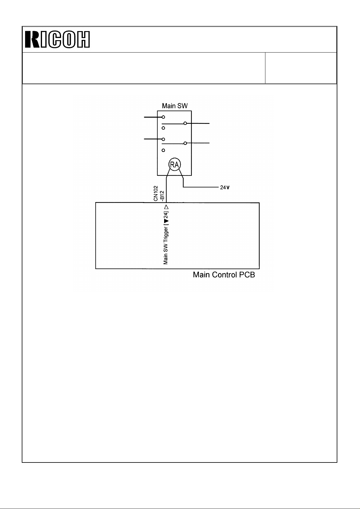
Definition : The main switch does not turn
off after sending the reset signal
two times in a row.
Point to check : • Main Switch
• Main PCB
Because the auto off mode and default duplex mode are explained in the Operating
Instructions, make sure that the customer understands how the machine operates to save
energy.
NOTE: The Thunderbird II type X has complied with the Energy Star requirements from
the first mass-production.
Page 6
Technical Bulletin No. RTB-003
SUBJECT: 1. Required Action for Energy Star Compliant Machines
(North American versions only)
2. Mode Change in Tab Copying (All versions)
DATE: February
29, ’96
PAGE: 2 of 4
For the cut-in serial numbers, please refer to MB #13.
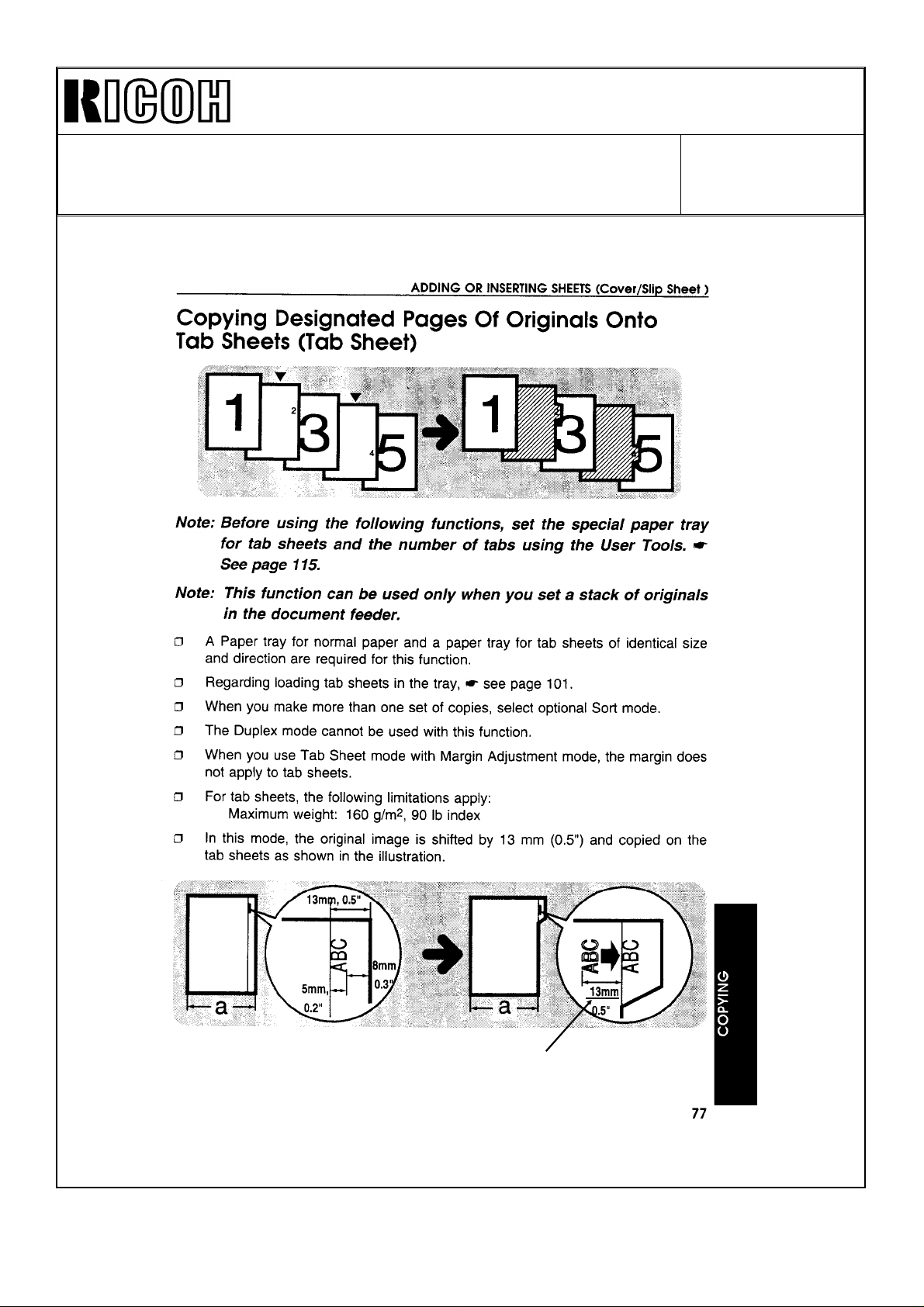
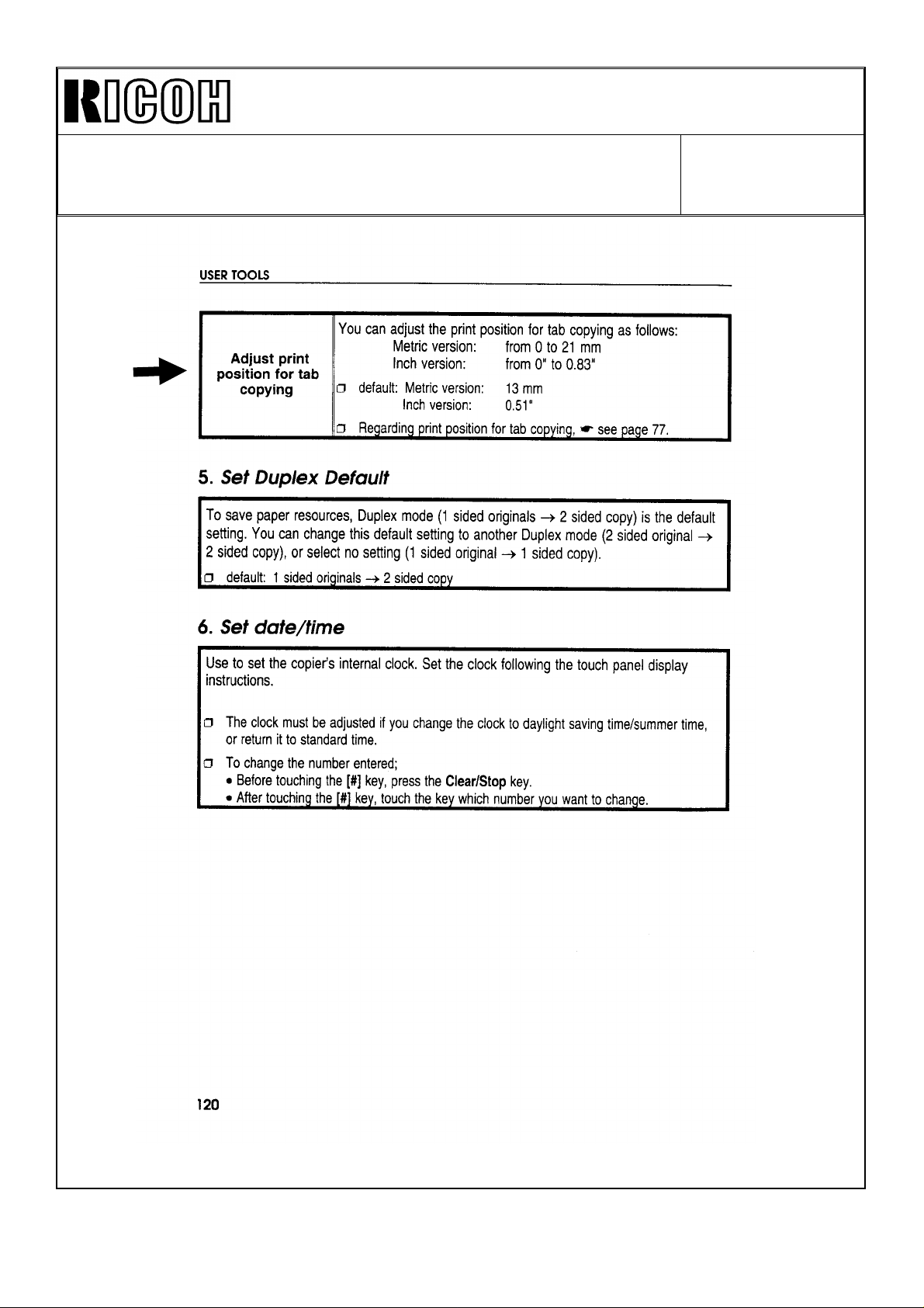
2. Tab Copy Mode
A function to adjust the print position for tab copying has been added.
(See the attached copy from the Operating Instructions.)
NOTE:
This function was available on the Thunderbird ΙΙ type X from the first
mass-production.
Page 7
Technical Bulletin No. RTB-003
SUBJECT: 1. Required Action for Energy Star Compliant Machines
(North American versions only)
2. Mode Change in Tab Copying (All versions)
DATE: February
29, ’96
PAGE: 3 of 4
This value adjustable
Page 8
Technical Bulletin No. RTB-003
SUBJECT: 1. Required Action for Energy Star Compliant Machines
(North American versions only)
2. Mode Change in Tab Copying (All versions)
DATE: February
29, ’96
PAGE: 4 of 4
Page 9
REVISED ON: MARCH 15, ’96
Technical Bulletin No. RTB-004
SUBJECT: Supplemental software upgrade information DATE: February
29, ’95
PAGE: 1 of 1
PREPARED BY: M. Mimura
FROM: 2nd Technical Support Section
CHECKED BY:
CLASSIFICATION:
Action Required
Troubleshooting
Retrofit Information
Revision of service manual
Information only
Other
MODEL:
Thunderbird - II
This RTB introduces minor software modifications applied to the new version ROM in MB
#13. Primary software modifications were introduced in RTB # 003.
Title Change
Dirty background Some copies with a dirty background had appeared when making
ADS copies in SP mode. This was because the lower bias limit had
been eliminated to facilitate factory adjustment. A lower bias has
now been restored to correct this problem per field request.
Combining tab and
staple modes
Designated page
copying restriction
A2 Copying (-22, -26,
- 27 versions only)
Selecting tab copying and staple copying at the same time has been
disabled.
Designated page copying onto tab sheets has been disabled in the
platen and SADF modes.
A3 double count mode (SP Special Feature P. 6-6) has been
changed as follows: Reset Set
Set Paper Size A3 A2 A3 A2
==================================================
Total Counter 1 1 → 222 → 4
A3 Counter 1 1 → 211 → 2
I
I
I
I
I
I
OHP slip sheet mode UP mode #4 [Select Special Modes]
In OHP slip sheet mode, blank slip sheets are added by default. If a
customer selects this feature, copies are made onto the slip sheets.
Default: No
Inverter pinch roller
solenoid
The energizing of the inverter pinch roller solenoid timing has been
changed from 40 to 20 ms after the paper passes through the fusing
sensor. This is a timing optimization for tab sheet copying.
Side to side
registration
After finishing the interrupt copying, the lens did not return to the
position where the lens was before the interruption.
Example:
DF mode copying -> Interrupt -> Platen mode copying (lens moves)
-> Leave Interrupt -> DF mode copying (lens stays in the platen
mode position)
This malfunction has been corrected.
For part number and cut-in serial number information, refer to MB # 13.
Page 10

Technical Bulletin No. RTB-005
[A]
[C]
[B]
SUBJECT: New Oil Supply System Information (European versions only) DATE: February
29, ’96
PAGE: 1 of 2
PREPARED BY: M. Mimura
CHECKED BY:
CLASSIFICATION:
Action Required
Troubleshooting
Retrofit Information
This RTB details the changes that the field technicians need to know when installing
and servicing the machines which have the new oil supply system (as detailed in MB #
10).
(NOTE:All the Thunderbird II type X machines have the new oil supply system.
The iformation described here is included in the type X Service Manual.)
1. At Installation
The securing brackets (shipping retainer) are being used to fix the new oil supply roller.
These brackets need to be removed at installation using the following procedure:
Revision of service manual
Information only
Other
FROM: 2nd Technical Support Section
MODEL:
Thunderbird II
[D]
[B]
1. Pull out the fusing unit.
2. Remove the upper fusing entrance guide [A] (4 screws).
3. Remove the oil supply roller securing brackets [B] (2 screws).
4. While pushing the bushing [C] inwards, put back the screws [D].
5. Re-install the upper fusing entrance guide and push the fusing unit back in.
Page 11

Technical Bulletin No. RTB-005
[F]
SUBJECT: New Oil Supply System Information (European versions only) DATE: February
29, ’95
PAGE: 2 of 2
2. PM Items and Intervals
Parts
Oil Supply Roller
Oil Supply Cleaning Roller
Oil Supply Cleaning Blade
Oil Supply Roller Bushing
R: Replacement
3. Parts Replacement Procedure
[A]
150K 300K 450K 600K
RRRR
RRRR
RRRR
RR
[G]
[C]
[C]
[H]
[B]
[G]
[B]
[F]
[G]
1. Pull out the fusing unit.
2. Remove the upper fusing entrance guide [A] (4 screws).
3. Remove 2 springs [B] and 2 screws [C].
4. Remove the oil supply roller [D] and oil supply cleaning roller [E] (2 shoulder
screws [F] and 2 oil supply roller bushings [G]).
5. Remove the oil supply cleaning roller blade [H] (5 screws).
Important: On re-assembly, while pushing the bushing [G] inwards, put the
screws [C] back.
[D]
[E]
Page 12

REVISED ON: APRIL 30, ’96
Technical Bulletin No. RTB-006
SUBJECT: Developer leakage DATE: March 31,’96
PAGE: 1 of 3
PREPARED BY: M. Mimura
CHECKED BY:
CLASSIFICATION:
Action Required
Troubleshooting
Retrofit Information
<Symptom>
Developer leaks from the ends of the development unit.
<Cause>
The fluidity of the developer tends to becomes lower when the toner concentration in the
developer becomes higher. Therefore, when the toner density becomes too high, the
developer does not circulate smoothly and accumulates at both ends of the development
unit.
<Countermeasure>
a) Production modification
To reduce the amount of developer leakage, the following modifications have been
applied.
1. The rear side seal has been extended by 0.5mm to the front, and a two-sided tape
has been added under the front side seal and front drum seal (refer to MB No. 2).
Revision of service manual
Information only
Other
FROM: 2nd Technical Support Section
MODEL:
Thunderbird II
2. The front side seal has been extended by 2.0 mm to the rear (refer to MB No. 15).
b) Machines in the field
1. Reduce the toner concentration by changing the SP setting. (10. SP Special
Feature - 2 PAGE 3)
In actual conditions, make test copies before and after the toner density adjustment
to compare of the copy density. To minimize the developer leakage problem, try to
reduce the toner density to the lowest limit that the customer accepts. The image
density drop caused by this procedure is none or minimal.
Current Position Lower Position
HIGH NORMAL
NORMAL LOW
(NOTE : There is possibility of having a toner adhering problem on the development
roller with extremely high toner concentration.)
2. Replace the front and rear side seals. This RTB contains information about how to
adhere the side seals to the development unit to prevent the developer leakage
which can occur if the seals are installed incorrectly.
Page 13

REVISED ON: APRIL 30, ’96
[C]
0 ~ 0.3mm
17.0mm
19.0mm
Technical Bulletin No. RTB-006
SUBJECT: Developer leakage DATE:March 31,’96
PAGE: 2 of 3
<Replacement Procedure>
[Front side]
1. Clean with alcohol the places of the development unit where the seals are to be
adhered.
2. Adhere the two sided tape [A] as shown.
NOTE: The lower casing and the front side plate are not flush where the two-sided tape is
to be pasted [B]. Carefully stick the tape to completely block the path that the
developer may leak through.
3. Adhere the front side seal [C] as shown. (The top left corner is the seal’s alignment
point.)
Width of the front side seal New part 19.0 mm
Old part 17.0 mm
4. Adhere the front drum seal [D] as shown. (The right edge is the alignment point.)
[A]
[B]
2~2.5mm
0~1mm
[D]
0 ~ 0.5mm
Page 14

REVISED ON: APRIL 30, ’96
17.0mm
17.5mm
Technical Bulletin No. RTB-006
SUBJECT: Developer leakage DATE:March 31,’96
PAGE: 3 of 3
[Rear sided]
1. Clean with alcohol the places of the development unit where the seals are to be
adhered.
2. Adhere the rear side seal [E] as shown. (The top right corner is the seal’s alignment
point.)
Width of the rear side seal New part 17.5 mm
Old part 17.0 mm
(For your reference)
In case you need to replace the rear drum seal [F], position its left edge so it
comes in contact with the development unit as shown.
NOTE: It is not necessary to replace this seal for this troubleshooting purpose.
0 ~ 0.3mm
0 ~ 0.3mm
[E]
[F]
<Confirmation Step>
Run the copier in the free run mode for the time required for 100 copies. If you observe
only a little or no developer leakage, the seals have been replaced correctly.
Page 15

Technical Bulletin No. RTB-007
SUBJECT: White Noise Condition (No Monitor Display) - Ricoh and
NRG European Type Y only
PREPARED BY: M. Mimura
CHECKED BY:
CLASSIFICATION:
Action Required
Troubleshooting
Retrofit Information
<Symptom>
Image is not displayed on the CRT screen correctly.
<Cause>
The internal electrical terminal is out of position and has unstable contact with the CRT
body.
<Solution>
Revision of service manual
Information only
Other
FROM: 2nd Technical Support Section
DATE:March 31, ’95
PAGE: 1 of 4
MODEL:
Thunderbird II
CAUTION: The CRT unit holds an electrical charge approximately three hours
after the main switch is turned off. Therefore, it is recommended to perform this
inspection on all suspected machines before the machine is powered up at
installation. If an electrical charge remains, touching the terminal with bare hands
will cause an electrical shock.
Correctly position the electrical terminal with the following procedure:
1. Ensure that you are working on a new machine which has never been powered up,
or on a field machine which has been off for more than three hours.
Suggestion: If you are not sure about the charge condition, perform "Optional
Procedure to discharge the CRT display" on page 3.
2. Remove the CRT rear cover [A] (4 screws).
[A]
Page 16

Technical Bulletin No. RTB-007
[C]
SUBJECT: White Noise Condition (No Monitor Display) - Ricoh and
NRG European Type Y only
3. Remove the operation control board [B] (4 screws).
4. Remove the inner shielding cover [C] (4 screws).
NOTE: Be careful not to hit the CRT display control unit [D] which is connected to
the CRT display [E].
[E]
DATE: March 31, ’95
PAGE: 2 of 4
[B]
5. Manually peel off a part of the rubber cap [F] and check if both terminals [G]
are in the hole, as s hown.
[G]
[Correct]
[Wrong]
[F]
[D]
Page 17

Technical Bulletin No. RTB-007
SUBJECT: White Noise Condition (No Monitor Display) - Ricoh and
NRG European Type Y only
6. If the terminal is out of position, reposition it using long nosed pliers.
7. Reassemble all parts.
NOTE: Even the terminal is out of the hole, the problem will not necessarily occur. This
is because the terminal is in contact with the outer surface of the CRT display.
However, machine vibration may break the contact.
DATE:March 31, ’95
PAGE: 3 of 4
Optional Procedure to discharge the CRT display
If the machine is already in use at a customer site, and you must go through this
procedure before the proper time allowed for electrical discharge, the CRT display can
be discharged by grounding the terminal as follows:
• Connect the CRT main frame [H] and one terminal [I] with a screwdriver rod (metal
portion) as shown in the illustration.
CAUTION : 1. Touch the main frame first for safety.
2. Never hold the screw driver rod with your bare hand while
doing this procedure.
[H]
[I]
Page 18

Technical Bulletin No. RTB-007
SUBJECT: White Noise Condition (No Monitor Display) - Ricoh and
NRG European Type Y only
<Suspected Machines>
The following table shows the machines that may have this problem.
Brand Code Total Q’ty Serial Numbers
NRG A171-22 3 9276020010 to -0012
Ricoh A171-27 58 A3876020126 to -0129
-0131 to -0134
-0136 to -0137
-0139 to -0146
-0148 to -0149
-0154 to -0167
-0170 to -0195
DATE:March 31, ’95
PAGE: 4 of 4
Page 19

Technical Bulletin No. RTB-008
SUBJECT: False jam condition cannot be reset / SC900 DATE: April 15,’96
PAGE: 1 of 2
PREPARED BY: M. Mimura
CHECKED BY:
CLASSIFICATION:
Action Required
Troubleshooting
Retrofit Information
<Symptom>
The machine indicates a paper jam and cannot recover from the jam condition. This
occurs only when feeding from the LCT.
<Cause>
Static built up during paper feed damages IC110 on the copier main board.
<Solution>
1. Install the diode harness in the LCT. Refer to the attached Product Update Information
for the correct installation of the diode harness.
2. Make sure that the grounding wire is fixed on the copier as shown in the Installation
Procedure / Service Manual.
IMPORTANT: Connecting this ground wire on the LCT frame will not ground the LCT.
Revision of service manual
Information only
Other
FROM: 1st Field Information Dept. QAC
MODEL:
Thunderbird II
Grounding Wire
<Factory Countermeasure>
1. The diode harness has been installed at the factory. Refer to MB # 3 of the
Thunderbird II LCT for cut-in serial numbers.
2. The grounding wire will be fixed to the copier main frame at the factory from the May
production machines.
Page 20

Technical Bulletin No. RTB-008
SUBJECT: False jam condition cannot be reset / SC900 DATE: April 15, ’95
PAGE: 2 of 2
Page 21

Technical Bulletin No. RTB-009
SUBJECT: Software upgrade Information DATE: January 15, ’97
PAGE: 1 of 2
PREPARED BY: M. Mimura
CHECKED BY: T. Inoue
CLASSIFICATION:
Action Required
Troubleshooting
Retrofit Information
This bulletin is to inform you of the modifications included in the A and B versions of the
ROM.
ROM Part Numbers
Type Y Type X
North America
(-10, -15, -17)
A1715216 A1715316 A1705211 A1705311
A1715217 A1715317 A1705212 A1705312
A1715226 A1705221
Version Problem Modification Occurs on
" #410 " (Right Scale Solenoid)
is incorrectly displayed when the
A
B
solenoid/clutch check is enabled.
When the copier starts from the
weekly timer mode, the Mode
Clear key will not work.
The vacuum solenoid cannot be
energized due to overheating.
When the reduction is
automatically selected as the
CFF original is set, the trailing
edge erase is delayed and the
leading edge of the next original
may be copied.
Tab mode cannot be selected in
the platen or SADF mode
A registration jam occurs in Sort
Tabs mode.
The trailing edge erase is
delayed in the combination of all
edge, reduction, and left margin
modes
(-22, -26, -27)
Revision of service manual
Information only
Other
Europe
FROM: 1st Field Information Dept. QAC
MODEL:
Thunderbird II
North America
(-10, -15, -17)
The bug has been
eliminated.
The bug has been
eliminated.
The ON timing has
been optimized.
Timing of the trailing
edge erase has been
changed to prevent
copying of the
leading edge of the
next original.
Tab mode can be
selected
The bug has been
eliminated.
The bug has been
eliminated
North America
version Type Y
All non-Energy Star
compliant Type Y
Type X
Type X and Y
Type X and Y
Type X
Type X and Y
Europe
(-22, -27)
Page 22

Technical Bulletin No. RTB-009
SUBJECT: Software upgrade Information DATE: January 15, ’97
PAGE: 2 of 2
When stapling in the
duplex to simplex copy
mode, the maximum
original message is
displayed at 50.
Cut-in Serial Numbers
Version Type Y Type X
-10: 9286080001
-15: 3A26030001
A
B
-17: A3876030001
-22: 9276030001
-26: 3H40360001
-27: A3876030068
-10: 9286080001
-15: 3A26060001
-17: A3876060001
-22: 9276060001
-26: 3H40660001
-27: A3876060172
It has been corrected to
25. At the 25th sheet,
"Maximum staple
capacity is 50 sheets.
Press Start Key to
continue without
stapling. Press Cancel
Key to stop copying" is
displayed.
N/A (From first mass
production)
-10: 9306100001
-15: 3A96060001
-17: A3946060001
-22: 9296090001
-27: A3946060031
Type X
Page 23

RICOH Technical Bulletin
Model: Thunderbird II Date: 28-Feb-97
Subject: Software Update Information Prepared by: M. Mimura
From: QAC 1st Field Information Dept. Checked by: T. Inoue
Classification:
This bulletin is to inform you of the modifications included in the C-version ROM.
ROM Part Numbers
North America
(10, -15, -17)
A1715216 A1715316 A1705211 A1705311
Troubleshooting
Mechanical
Paper path
Other ( )
Type Y Type X
Europe
(-22, -26, -27)
Part information
Electrical
Transmit/receive
North America
(-10, -15, -17)
No: 010
Action required
Service manual revision
Retrofit information
Europe
(-22,27)
1/5
A1715217 A1715317 A1705212 A1705312
A1715226 A10705221
Problem Modification Occurs in
The potential sensor output drifts,
causing improper process control. In
the worst case, an excessive amount
of developer drops due to high toner
concentration
When the 2 to 2 duplex and Tab
Sheet modes are selected, the
finisher shift tray shifts erratically in
the middle of a set.
When resuming copying after the
copier has been stopped by the bin
MAX limit in the CFF, the same page
is copied twice.
A detection process has been
added to the process control.
If the drift is defected, SC306
is displayed. See the following
pages for more details.
This bug has been fixed. Type X
When the bin MAX stops the
copier, the computer form
does not feed.
Therefore, when resuming, the
same page is copied again.
The computer form is fed at
bin MAX.
Type X and Y
Type Y
In the CFF mode, dual-sort and large
volume sort functions do not work.
(Stops after the bin MAX detection.)
This bug has been fixed. Type Y
Page 24

RICOH Technical Bulletin
Model: Thunderbird II Date: 28-Feb-97 No: 010 2/5
Cut-in Serial Numbers
Type Y Type X
-10: 928703XXXX
-15: 3A27020001
-17: A3877020001
-22: 927703XXXX
-26: 3H40370001
-27: A3877020100
-10: 930703XXXX
-15: 3A9703XXXX
-17: A3947020001
-22: 9297020001
-27: A3947020037
Page 25

RICOH Technical Bulletin
Model: Thunderbird II Date: 28-Feb-97 No: 010 3/5
Page 26

RICOH Technical Bulletin
Model: Thunderbird II Date: 28-Feb-97 No: 010 4/5
Page 27

RICOH Technical Bulletin
Model: Thunderbird II Date: 28-Feb-97 No: 010 5/5
Page 28

RICOH Technical Bulletin PAGE: 1/2
Model: Thunderbird II Date: 15-Mar-97
Subject: White spots on copies caused by developer leakage Prepared by: M. Kitajima
From: QAC 1st Field Information Dept. Checked by: T. Inoue
Classification:
Troubleshooting
Mechanical
Paper path
Other ( )
Part information
Electrical
Transmit/receive
Action required
Service manual revision
Retrofit information
No: 11
SYMPTOM
White spots on copies caused by developer leakage
CAUSE
The fluidity of the developer tends to become lower when the toner concentration in the
developer becomes higher. Therefore, when the toner density becomes too high, the
developer does not circulate smoothly and leaks from the development unit.
SOLUTION
When this problem occurs in machines in the field, do the following steps in the order
noted: If the problem still exists, do the next step.
1. Adjust the charge corona wire height. (When the copy image density at the machine’s
rear side is lower than that at the machine’s front side)
Reason: The ID sensor is not at the center (it is at the machine’s rear side). When the
ID at the machine’s rear side (left side of the copy) is lower than at the front
side (right side), toner is supplied because the machine detects a low toner
concentration in the developer.
2. Reduce the toner concentration by changing the SP setting (10. SP Special Feature -
2 PAGE 3).
Make test copies before and after the toner density adjustment to compare the copy
density. To minimize the developer leakage problem, try to reduce the toner density to
the lowest limit that the customer will accept. The image density drop caused by this
procedure is none or minimal.
Current Position →→ Lower Position
HIGH NORMAL
NORMAL LOW
Page 29

RICOH Technical Bulletin PAGE: 2/2
Model: Thunderbird II Date: 15-Mar-97
3. Apply the modified front and rear side tapes to the development unit to reduce the
developer leakage. Refer to RTB No. 6
4. Install the new potential sensor bracket (# A1672105). Refer to MB No. 29.
Reason: If the potential sensor bracket is not set properly, the potential sensor output
may drift, causing improper process control.
5. Install the C-version ROMs. Refer to RTB No. 10.
Reason: If the potential sensor output drifts, proper process control is not performed,
causing improper toner concentration in the developer.
No: 11
 Loading...