

Page 1

RICOH FT8880
SERVICE MANUAL
This manual is an insert upgrade which covers only the
points where the FT8880 (A083) differs from the FT8780
(A084). Refer to the FT8780 service manual for any items
not covered here.
Page 2

IMPORTANT SAFETY NOTICES
PREVENTION OF PHYSICAL INJURY
1. While the machine warms up, it will suddenly start turning to perform the
process control data initialization. Keep hands away from any mechanical
and electrical components during this period.
2. Before disassembling or assembling parts of the copier and peripherals,
make sure that the copier and the second sorter power cord is unplugged.
3. The wall outlet should be near the copier and easily accessible.
4. Note that some components of the copier, the paper tray unit, and the
peripherals are supplied with electrical voltage even if the main switch is
turned off.
5. If any adjustment or operation check has to be made with exterior covers
off or open while the main switch is turned on, keep hands away from
electrified or mechanically driven components.
6. The inside and the metal parts of the fusing unit become extremely hot
while the copier is operating. Be careful to avoid touching those
components with your bare hands.
HEALTH SAFETY CONDITIONS
1. Never operate the copier without the ozone filters installed.
2. Always replace the ozone filters with the specified ones at the specified
intervals.
3. Toner and developer are non-toxic, but if you get either of them in your
eyes by accident, it may cause temporary eye discomfort. Try to remove
with eye drops or flush with water as first aid. If unsuccessful, get medical
attention.
Page 3

OBSERVANCE OF ELECTRICAL SAFETY STANDARDS
1. The copier and its peripherals must be installed and maintained by a
customer service representative who has completed the training course
on those models.
2. The RAM board on the main control boards on the copier and the RDH
has a lithium battery which can explode if replaced incorrectly. Replace
the battery only with an identical one. The manufacturer recommends
replacing the entire RAM board. Do not recharge or burn this battery.
Used batteries must be handled in accordance with local regulations.
SAFETY AND ECOLOGICAL NOTES FOR DISPOSAL
1. Do not incinerate the toner cartridge or the used toner. Toner dust may
ignite suddenly when exposed to open flame.
2. Dispose of used toner, developer, and photoconductors according to
local regulations.
3. Dispose of replaced parts in accordance with local regulations.
4. When keeping used lithium batteries in order to dispose of them later, do
not put more than 100 batteries per sealed box. Storing larger numbers or
not sealing them apart may lead to chemical reactions and heat build-up.
Page 4

SECTION 1
OVERALL MACHINE
INFORMATION
Page 5

Overall
Information
5 June 1992 SPECIFICATIONS
1. SPECIFICATIONS
Main Copier
Copier
Configuration: Console
Copy Process: Dry Electrostatic Transfer System
Originals: Sheet/Book
Original Size: Maximum: 11" x 17", A3
Copy Paper Size: Maximum: 1st and 2nd tray 8
1/2" x 14", A4
3rd tray 11" x 17", A3
Minimum: 1st and 3rd tray 5
2nd tray 8
1/2" x 81/2", A5
1/2" x 11", A4
Copy Paper Weight: Standard Copying: 14 ~ 42 lb, 52 ~ 157 g/m
Duplex Copying: 17 ~ 28 lb, 64 ~ 105 g/m
Warm Up Time: Within 8.0 minutes (room temp. 68°F, 20°C)
First Copy Time: 4.8 seconds (8
Copying Speed: 80 copies/minute (8
1/2" x 11", A4, feed from 2nd tray)
1/2" x 11", A4)
60 copies/minute (11" x 17", A3)
Optional Equipment: Menu Reader
Key Counter
Guidance ROM Kit
Reproduction Ratios: See the following table:
LT/DLT version A4/A3 version
200% 200%
Enlargement
155% 141%
129% 122%
121% 115%
Full Size 100% 100%
93% 93%
77% 82%
Reduction
74% 71%
65% 65%
50% 50%
2
2
1-1
Page 6

SPECIFICATIONS 5 June 1992
Zoom: 50 ~ 200%
Toner Replenishment: Cartridge exchange (1,500 g)
Paper Feed: 1st tray (550 sheets)
2nd tray (3,000 sheets)
3rd tray (1,500 Sheets)
Power Source: 120 V, more than 20 A (LT/DLT version)
220, 230, 240 V, more than 10 A (A4/A3 version)
Power Consumption:
Maximum during LT/DLT version A4/A3 version
Stand-by 2.01 kw 2.00 kw
Copying Cycle 1.85 kw 1.89 kw
Dimensions: Copier Only: 65.4" x 30.0" x 56.9"
(1660 x 760 x 1444.5 mm)
With Finisher: 83.1" x 30.0" x 56.9"
(2110 x 760 x 1444.5 mm)
Weight: Copier Only: 917 lb/422 kg
With Finisher: 1027 lb/472 kg
Noise Emission: With Finisher/RDH:
Maximum: less than 70 db
Copy-cycle: less than 69 db (average)
Warm-up: less than 42 db
1-2
Page 7
Overall
Information
5 June 1992 SPECIFICATIONS
Recycling Document Handler
Original Size:
Stack feed mode Single feed mode CFF mode
Maximum 11" x 17", A3 11" x 17", A3 11" x 9
Minimum 8" x 10
Original Weight:
Stack feed mode Single feed mode CFF mode
Maximum 28 lb, 105 g/m
Minimum 17 lb, 64 g/m
Number of originals to be set:
Weight
Size
A3/11" x 17" 30 sheets 20 sheets
Others 50 sheets 30 sheets
1/2", A4 51/2" x 81/2", A5
2
43 lb, 165 g/m
2
14 lb, 52 g/m
64~81 g/m
2
17~21 lb
2
20 lb, 80 g/m
2
17 lb, 64 g/m
82~105 g/m
22~28 lb
8
1/2" x 12"
11" x 14
1/2"
7/8"
2
2
2
Number of Recycles: Maximum: 60 times
CFF Original Stack Height:Maximum: 50 mm
Original Set: First sheet on top, stack face down
1-3
Page 8
MECHANICAL COMPONENT LAYOUT 5 June 1992
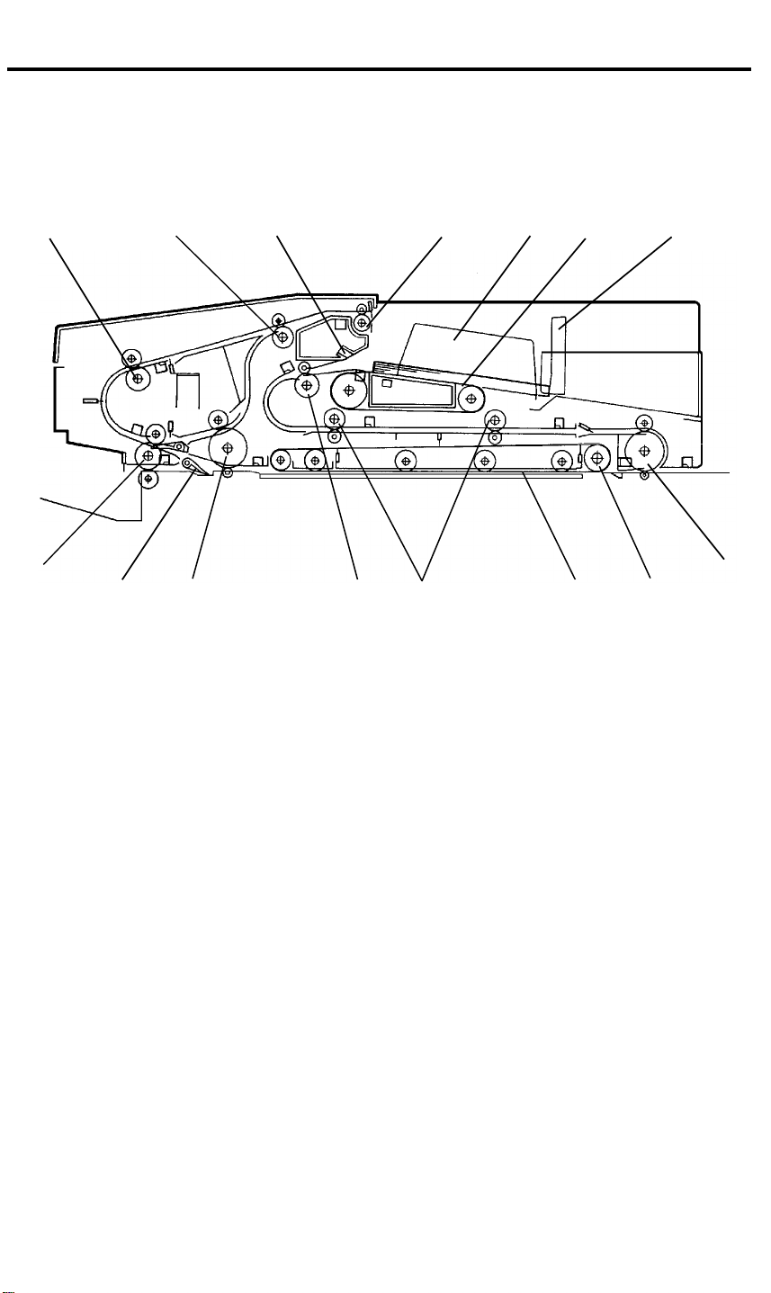
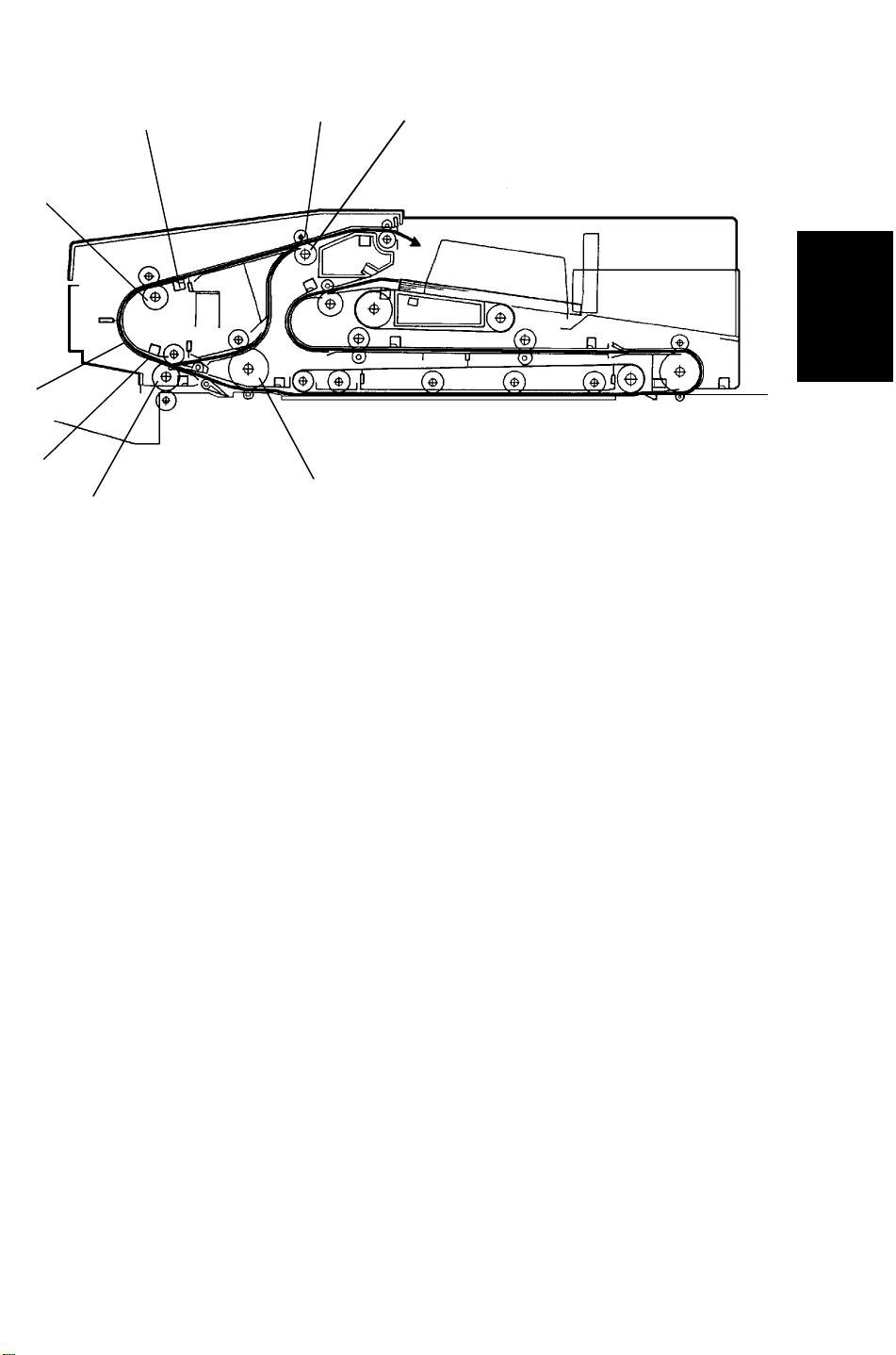
3. MECHANICAL COMPONENT LAYOUT
3.2 RDH
15
1
2
14 13 12 10 9
3 4 5
11
6
7
8
1. Inverter Roller
2. Inverter Exit Roller
3. Air Knife Nozzle
4. Exit Roller
5. Original Guide
6. Feed-in Belt
7. Original Stopper
8. Right Turn Roller
9. Belt Drive Roller
10. Transport Belt
11. Transport Rollers
12. Original Feed Roller
13. Inverter Entrance Roller
14. Single Feed Exit Gate
15. Inverter Middle Roller
1-4
Page 9

Overall
Information
5 June 1992 ELECTRICAL COMPONENT DESCRIPTIONS
4. ELECTRICAL COMPONENT DESCRIPTIONS
Refer to the electrical component layout on the reverse side of the Point to
Point (Water proof paper) index numbers.
4.2 RDH
Name Function Index No.
Motors
Feed Drives the feed and transport rollers. 3
Belt Drive Drives the transport belt. 7
Inverter Drives the inverter and exit rollers. 34
Blower Supplies air to the air knife and draws air from the
vacuum section.
Separator Drives the original separator. 21
Sensors
Original Set Detects if the original is set on the document handler. 31
Entrance Detects the original leading edge and de-energizes
the feed belt drive clutch.
1st Transport Detects jams in the transport section. 16
2nd Transport Detects the original leading edge and lowers the
original feed motor speed.
Registration Detects the original trailing edge for the original stop
position calculation.
Inverter Entrance Detects jams in the transport belt section. 24
1st Inverter Detects the original trailing edge and reverses the
inverter drive motor rotation.
2nd Inverter Detects the original leading edge and energizes exit
roller release solenoid.
Exit Detects the original leading edge and lowers the
inverter drive motor speed.
Single Feed Set Detects the leading edge of the original in the single
feed table and turns the original feed motor.
Single Feed Exit Detects jams in single feed mode. 25
Lift Detects if the RDH is open. 2
CFF Detects if the computer form is set in the CFF guide.
Counts the holes lined up to the computer form.
Original Length Detects if the original stopper is set for 8
Original Height Detects the original height on the RDH. 20
Separator H.P. Detects if the original separator is in the home
position.
Separator Detects if the last original of the original stack is fed. 23
Inverter Unit Cover
(Switch)
Original Width
(Potentiometer)
Detect if the inverter unit cover is opened.
Detects the original width in the stack feed mode.
1/2" position. 19
5
33
15
12
29
30
32
13
9
22
27
17
1-5
Page 10

ELECTRICAL COMPONENT DESCRIPTIONS 5 June 1992
Name Function Index No.
Single Feed Original
Width (Potentiometer)
Detects the original width in the single feed mode.
14
Solenoids
Vacuum Shutter Closes the vacuum shutter. 4
Single Feed Gate Lowers the single feed gate. 8
Single Feed Exit Lifts the single feed exit gate. 26
Exit Roller Releases the exit driven rollers from the exit drive
rollers.
28
Clutches
Feed Belt Drive Transmits the original feed motor drive to the feed
belt rollers.
10
Feed Belt Brake Stops the feed belt rotation. 11
PCBs
Main Control Controls overall RDH operation. 6
Blower Motor Control Controls the vacuum motor operation. 1
Indicator Indicates the single feed mode indicators. 18
1-6
Page 11

SECTION 2
DETAILED SECTION
DESCRIPTIONS
Page 12
5 June 1992 DEVELOPMENT
6. DEVELOPMENT
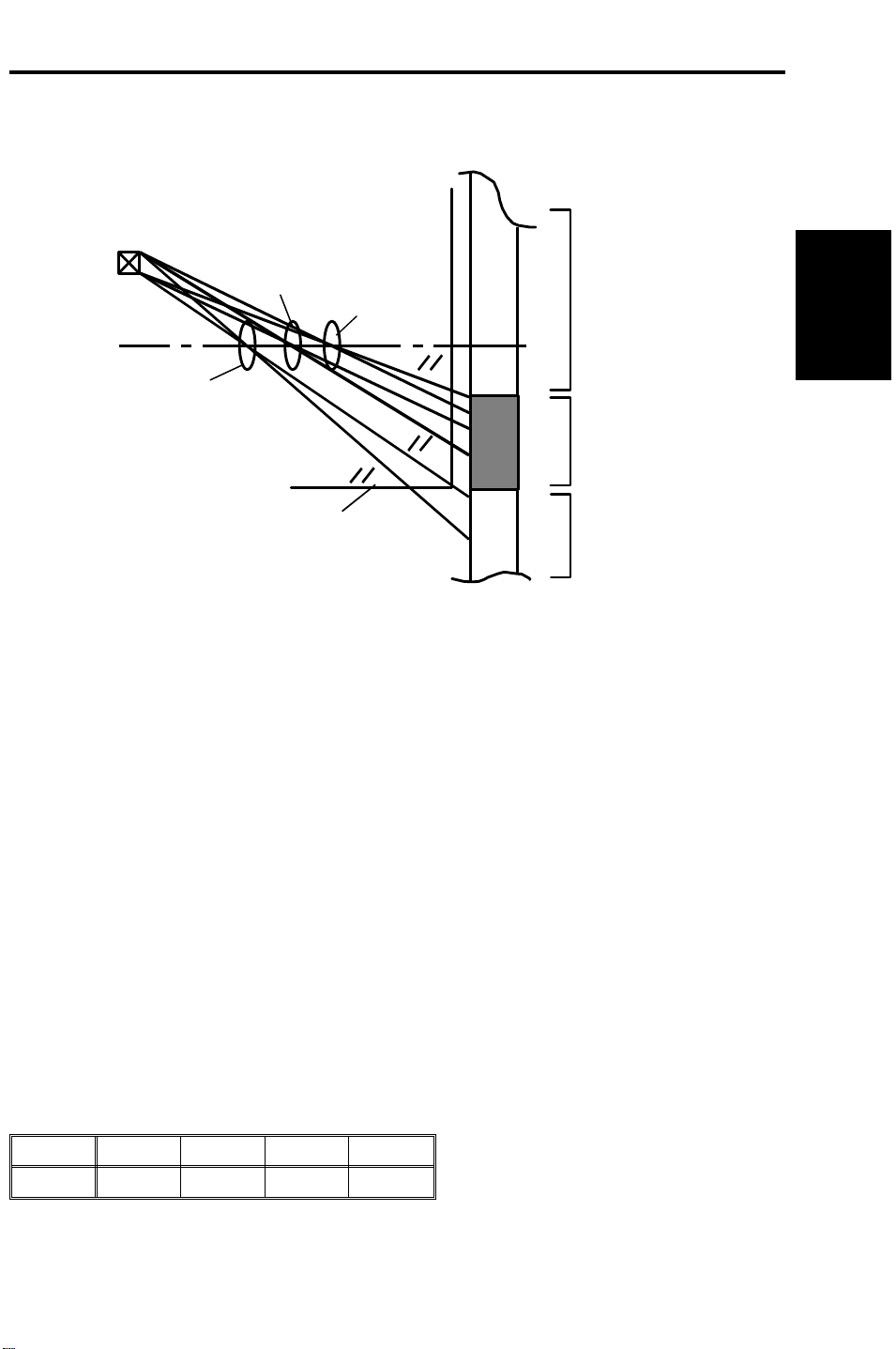
6.4.3 Bias for the ID Sensor Pattern
ID Sensor
Full Size
Enlargement
Reduction
VL Pattern
ID Sensor Pattern
Detailed
Descriptions
Exposure Glass
Outside
The ID sensor pattern cannot always be used for the image density detection
due to the position of the ID sensor and both the positioning and size of the
ID sensor pattern on the drum.
The outside of the exposure glass (no light) is exposed on the drum and used
as the ID sensor pattern in reduction mode.
The potential of the drum in these cases, the no light and the ID sensor
pattern exposure, is not the same. So the ID sensor bias (VBP) is determined
using two base voltages, V0 for the no-light condition and Vd for the pattern.
VBP (no light) = --360 + V0 (Reproduction ratio < 77%)
VBP (ID Pattern) = --360 + Vd (Reproduction ratio ≥ 77%)
The Vd value which is determined during the process control data
initialization will be used.
V01 and V02, which are explained in the process control section, are used for
the VBP calculation as the V0 (drum potential after the charge corona) value.
The VBP can be changed by the SP mode (Toner Density Correction).
The following compensation will be applied to the above VBP.
Setting L N H VH
(V) --60 0 +60 +120
Default: H (+60 V)
2-1
Page 13
RDH 5 June 1992
16. RDH
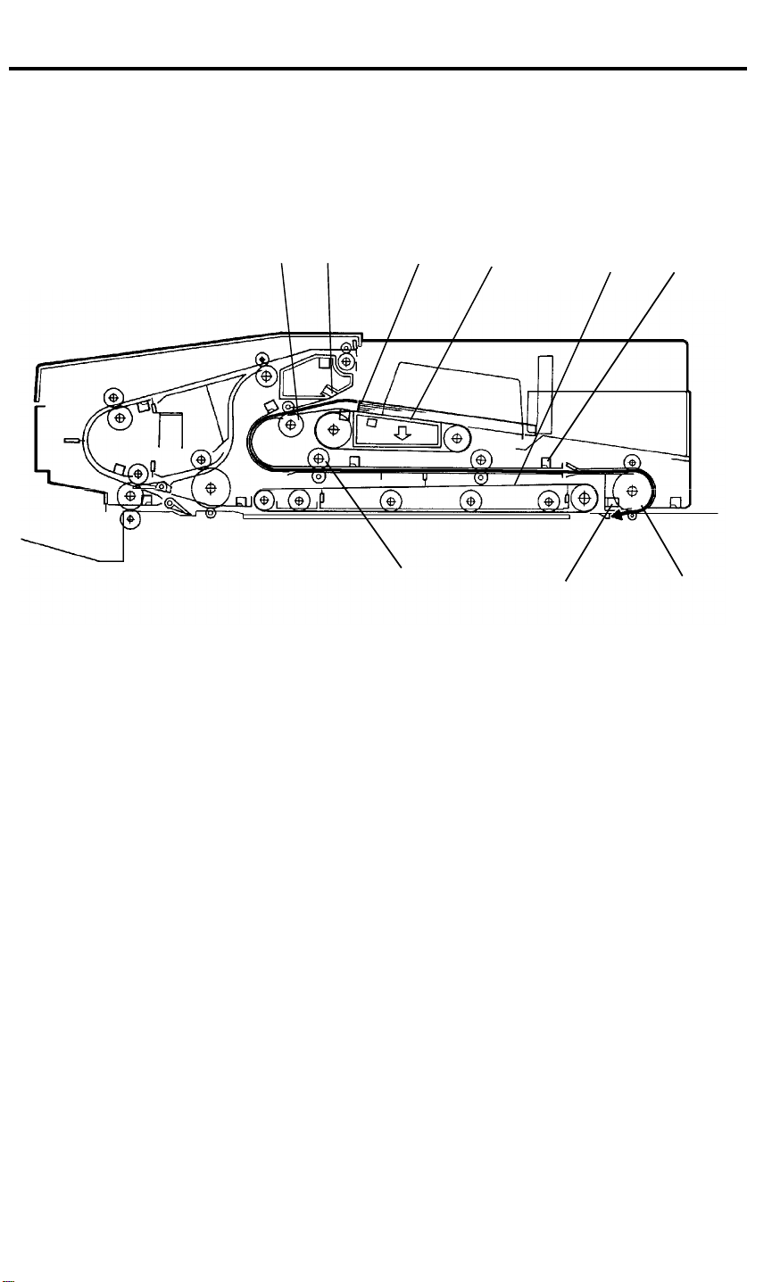
16.1 OVERVIEW
16.1.1 No Inversion Original Cycle
[E] [B]
When the start key is pressed, the blower motor start to rotate. It supplies air
to the air knife and draws air from the vacuum section. Sheets are separated
at the leading edge [A] of the paper stack. The air comes from the nozzle [B]
and the bottom sheet of the stack paper is held against the feed-in belts [C]
by air suction [D]. The feed motor drives the feed drive [E], transport [F], and
right turn [G] rollers. The bottom sheet of the paper is delivered through the
feed drive, transport, right turn rollers to the registration section [H] and is
stopped. To stop the original sheet at the proper position in the registration
section, the feed motor rotation speed is reduced by half when the 2nd
transport sensor [I] detects the leading edge of the original. The belt drive
motor then starts to rotate the transport belt [J] to direct the sheet of paper
onto exposure glass. At the same time, the next original is fed.
[F]
[A]
[D]
[C]
[H]
[J] [I]
[G]
2-2
Page 14
5 June 1992 RDH
[D]
[A]
[E]
[C]
[H]
[G]
[B]
[F]
Detailed
Descriptions
At the appropriate time, the transport belt delivers the original on the
exposure glass to the inverter section [A], and the following original is moved
onto the exposure glass, and the 3rd sheet of original is fed. The 1st original
is passed into the inverter section through the inverter entrance [B], inverter
middle [C], and inverter [D] rollers until the trailing edge of the original is
detected by the 1st inverter sensor [E]. The inverter middle [C] and inverter
[D] rollers then rotate in the opposite direction. The inverter exit rollers [F]
rotates only in the paper exit direction. However, the contact between the
inverter exit roller [F] and inverter exit driven roller [G] is released when the
2nd inverter sensor [H] is activated by the original. This way, the inverter exit
roller does not interfere with the original switch back cycle while the inverter
middle and inverter rollers begin reverse rotation. The original is delivered
through the inverter entrance [B] and inverter exit [F] rollers to the original
table. This continues until all originals have been returned to the original
table. The originals are stacked on the original table where they wait for the
next copy cycle.
2-3
Page 15

RDH 5 June 1992
16.1.2 Inversion Original Cycle
[A]
[B]
[B]
[C]
Until the original reaches to the inverter section [A], the sequence is the same
as for no inversion original cycle. The inverter rollers [B] rotate in the original
exit direction. The original is now inverted and exited to the original table [C].
This continues until all originals have been inverted. The inverted originals
are then fed from the original table for copying of the reverse side. The
sequence is the same as for the front side copying. The originals return and
are stacked on the original table where they wait for the next copy cycle.
2-4
Page 16
5 June 1992 RDH
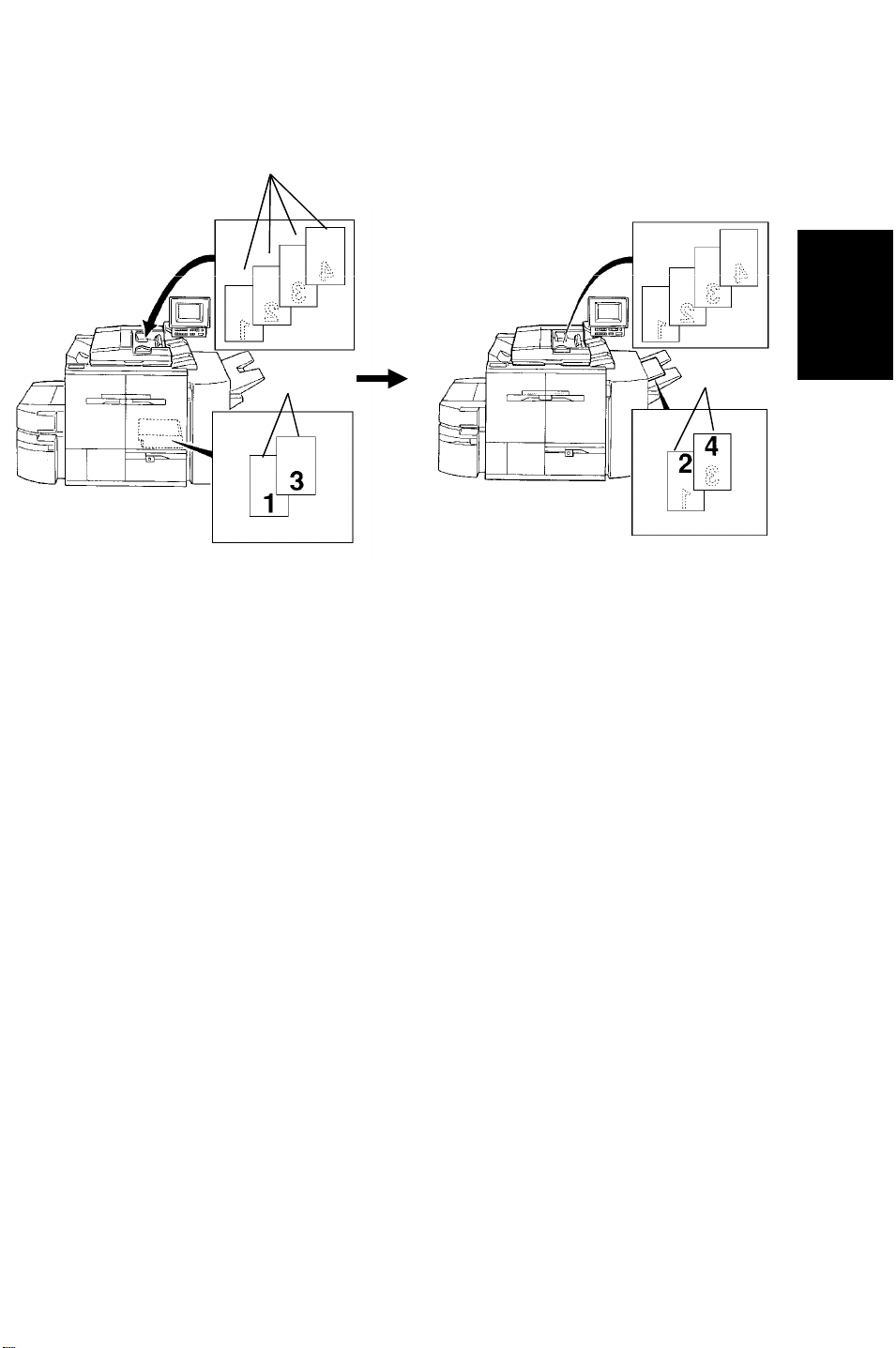
16.1.3 1 Sided Original 2 Sided Copy Mode
[A]
[B]
[C]
Detailed
Descriptions
No inversion original cycle is used for this mode.
All the originals [A] are fed starting from the bottom original sheet. First, odd
numbered originals (in case of the illustration: 1st and 3rd originals) are
copied and even numbered originals copy is skipped. The copied paper [B] is
stacked in the duplex tray. The originals are return to the original table, and
the original feed is then repeated. This time the odd numbered originals copy
is skipped and even numbered originals are copied on the reverse side of the
copy paper [C], which is fed from the duplex tray.
2-5
Page 17
RDH 5 June 1992
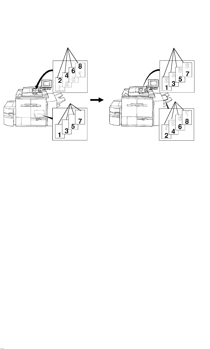
16.1.4 2 Sided Original 2 Sided Copy Mode
[A]
[B]
[C]
[D]
Inversion original cycle is used for this mode. All the originals [A] are fed
starting from the bottom original sheet. First, the front side of the originals are
copied. The copied paper [B] is stacked in the duplex tray. The originals [C]
are inverted and return to the original table. The original feed is then
repeated. This time the reverse side of the originals are copied on the
reverse side of the copy paper [D], which is fed from the duplex tray.
2-6
Page 18
5 June 1992 RDH
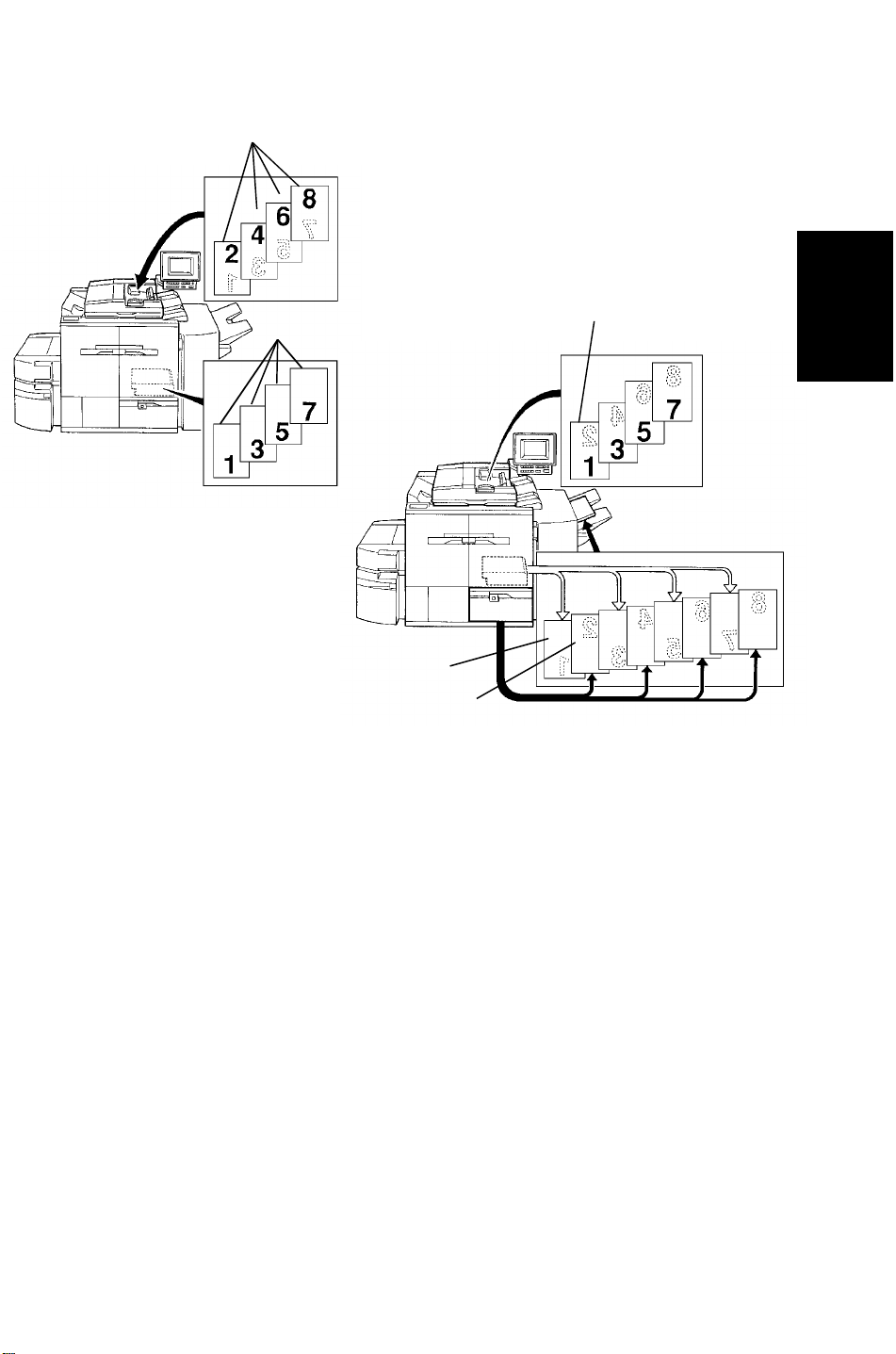
16.1.5 2 Sided Original 1 Sided Copy Mode
[A]
[D]
[B]
Detailed
Descriptions
[C]
[E]
Inversion original cycle is used for this mode. All the originals [A] are fed
starting rom the bottom original sheet. Firstly, the front side of all the originals
are copied and the copied paper [B] is stacked in the duplex tray. The
originals [C] are inverted and return to the original table. The original feed is
then repeated. This time, the bottom copy sheet is fed from the duplex tray
and exited from the copier without copying [C]. The reverse side of the
bottom original sheet [D] is then copied to paper [E], which is fed from the
paper tray, and the copy is exited from the copier [E]. This copy sequence
exiting from the duplex tray followed by the paper tray is alternately repeated.
2-7
Page 19
RDH 5 June 1992
16.2 ORIGINAL SET
16.2.1 Stack Feed Mode
[A]
[C]
[B]
[H]
[D]
[E]
[F]
[G]
1. Original set detection
The originals are detected by the original set sensor [A] when they are
stacked on the original table.
2. Size detection
The original width is detected by the original width sensor [B] under the front
original guide [C]. Moving the guide changes the value of the sensor. (The
sensor is a potentiometer.) The front original guide and rear original guide [D]
are moved by the racks [E] and pinion [F] at the same time. The actuator [G]
of the original stopper activates the original length sensor [H]
(photo-interrupter) to detect if the original stopper is set for the 81/2 inch
position. LG (81/2" x 14" = 216 x 356 mm) or B4 (257 x 364 mm) size is
distinguished by the combination of the original length sensor (activated or
not) and the value of the original width sensor. This is because the LG and
B4 widths are very close.
2-8
Page 20
5 June 1992 RDH
[B]
[E]
[E]
[A]
[F]
Detailed
Descriptions
[D]
[C]
[E]
3. Original separator
The original stack which has been fed and returned to the original table, and
the original stack which has not been fed yet, are separated by the original
separator [A] mechanism.
When the start key is pressed, the separator motor [B] rotates until the
original separator actuator [C] activates the separator home position sensor
[D]. The original separator is set on the original top sheet. The originals which
are fed and returned to the original table are stacked on the original
separator. When the last original (top sheet under the original separator) is
fed from the original table, the original separator drops and activates the
separator sensor [E].
If the next copy cycle continues, the separator motor rotates and the original
separator is set on the original top sheet again after the trailing edge of the
last original sheet passes through the exit sensor [F].
2-9
Page 21
RDH 5 June 1992
16.2.2 Single Feed Mode
[A]
[C]
[E]
[D]
[B]
[F]
1. Original set detection
The original is detected by the single feed set sensor [A] when the original is
set on the single feed table.
2. Size detection
The original width is detected by the single feed original width sensor [B]
under the rear original guide [C]. Moving the guide changes the value of the
sensor. (The sensor is a potentiometer.) The front original guide [D] and rear
original guide are moved by the racks [E] and pinion [F] at the same time. As
the original length sensor is not used for the single feed mode, the original
length is not detected. When the B4 or LG original is set on the single feed
table, the original size is determined by the machine version.
(U.S.A. version machine ... LG, Europe version machine ... B4).
2-10
Page 22
5 June 1992 RDH
16.3 ORIGINAL FEED
16.3.1 Original Separation/Feed (Original Stack Mode)
[A]
[B]
[E]
Detailed
Descriptions
[B]
[F]
[D]
[C]
[F]
[G]
[H]
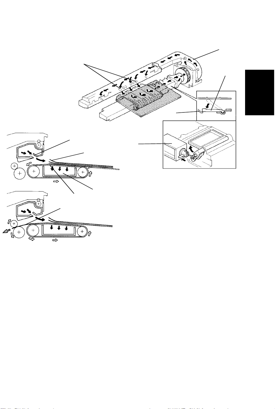
1. Air knife and shutter
The air from the blower motor [A] is blown through the air knife nozzles [B] to
the leading edge [C] of the original stack. The blower motor keeps blowing air
from the beginning to the end of the original stack mode to prevent
multi-feeding.
After the originals are separated by the air knife, the vacuum shutter solenoid
[D] is energized by a paper feed signal from the main PCB. The vacuum
shutter [E] closes the air hole on the vacuum duct [F]. The blower draws air
from the vacuum section [F]. The bottom sheet original [G] is held against the
feed-in belts by the suction. Until, the feed-in belt rotates. The bottom sheet
original [H] is then fed.
2-11
Page 23
RDH 5 June 1992
[A]
Table 1
Table 2
Small
Size
Large
Size
Small
Size
Large
Size
A4
8 x 101/2
81/2 x 11
81/2 x 13
B4
A3
81/2 x 14
10 x 14
11 x 17
A4
8 x 101/2
81/2 x 11
81/2 x 13
B4
A3
81/2 x 14
10 x 14
11 x 17
Original Height Sensor
OFF ON
3000 rpm
6000 rpm
3500 rpm
Number of Originals
5 or less from 6 to 12 13 or more
3000 rpm
6000 rpm
3500 rpm
2. Blower motor speed
To ensure good original separation and original re-stacking on the original
table, the blower motor speed is changed according to the original stack
height, or the number of originals stacked. The blower motor speed is
determined for the 1st copy cycle by the original stack height as detected by
the original height sensor [A] (Table 1). From the 2nd copy cycle, the blower
motor speed is determined by the number of originals counted by the main
PCB (Table 2).
When the number of the originals is 3 or less, the original set sensor is
de-activated when the last original is fed and before the 1st original returns to
the original table. During this period the blower motor stops rotating to ensure
correct stacking the originals.
2-12
Page 24
5 June 1992 RDH
16.4 SINGLE FEED MODE
16.4.1 Registration
[D]
[E]
[B]
[A]
[C]
Detailed
Descriptions
[D]
When the single feed set sensor [A] detects the leading edge of the original
the feed motor rotates and the right turn roller [B] transports the original. At
the same time the single feed gate solenoid [C] is energized and the single
feed gate [D] is lowered. The feed motor and single feed gate solenoid are
energized until the registration sensor [E] detects the leading edge of the
original. The original is transported until hits the single feed gate, which
corrects the original feed skew. At the same time the right turn roller stops
rotating.
2-13
Page 25

RDH 5 June 1992
16.4.2 Feed
[C]
[B]
[D]
[G]
[A]
[F]
[E]
When the start key is pressed, the right turn roller [A] and transport belt [B]
rotate. The original is delivered onto the exposure glass. After the scanner
scans the original, the transport belt start to rotate to deliver it. At the same
time the inverter entrance [C] and inverter middle [D] rollers rotate and the
single feed exit solenoid [E] is energized. The single feed exit gate [F] lifts up,
exiting the original to the left top cover [G].
16.4.3 Exit Gate
In single feed mode and CFF mode, the single feed exit solenoid is energized
while the belt drive motor is driving the transport belt, and is de-energized
when the transport belt stops rotating. This solenoid on off operation is
performed to keep the solenoid reliable.
2-14
Page 26
5 June 1992 RDH
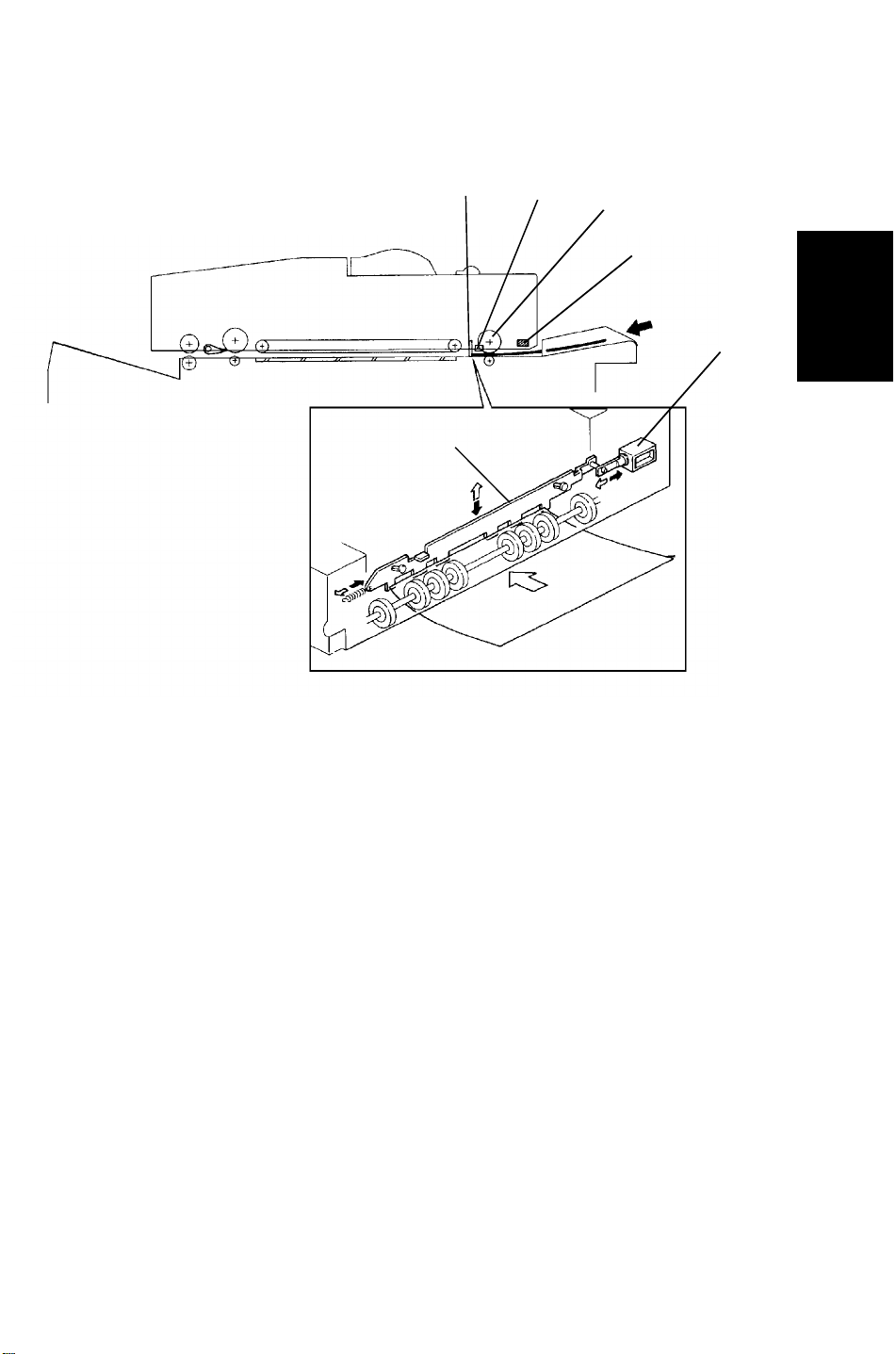
16.5 DRIVE MECHANISM
16.5.1 Feed Motor Drive
[H]
[A]
[D]
[B]
[A]
[G]
[C]
Detailed
Descriptions
[H]
[E]
[F]
[C]
All the feed rollers and transport rollers (with the exception of the feed belt
drive rollers [A]) begin to rotate together with the feed motor [B]. The feed belt
drive clutch [C] is energized according to the appropriate original feed timing.
When the clutch is energized, the feed motor drive will be transmitted through
the gears [D] and timing belt [E], and the feed belt brake clutch shaft [F] to
the feed belt drive rollers. The feed belt brake clutch [G] stops the feed belt
rotation when the feed belt drive clutch is de-energized to prevent
multi-feeding of originals. When the feed belt brake clutch is energized,the
rotating clutch disk [H] is stopped by the clutch which is fixed on the frame.
2-15
Page 27
RDH 5 June 1992
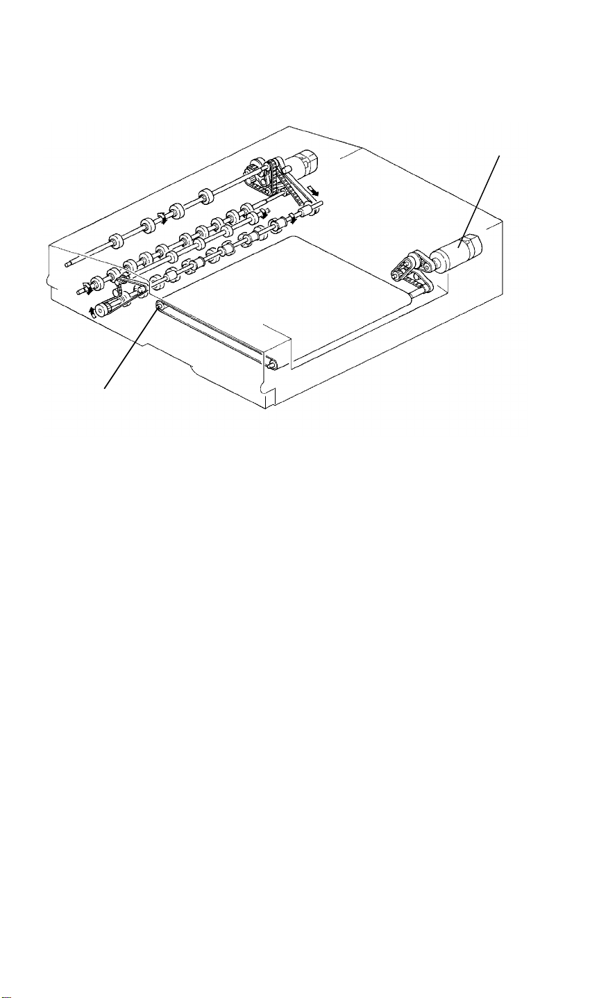
16.5.2 Belt Drive Motor Drive
[B]
[A]
The transport belt [A] is driven by the belt drive motor [B] via timing belts and
pulleys.
2-16
Page 28
5 June 1992 RDH
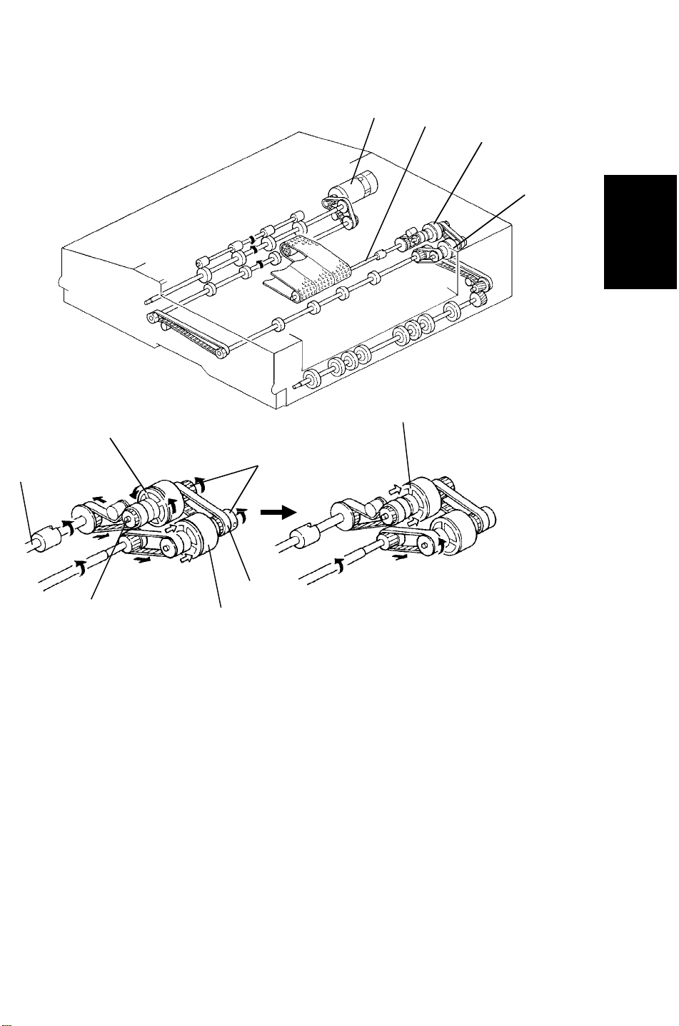
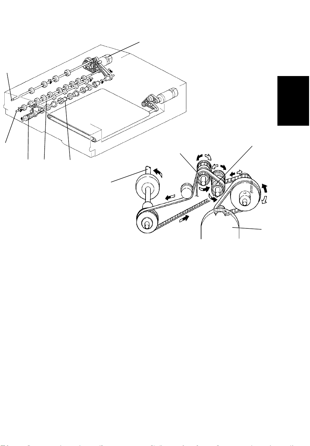
16.5.3 Inverter Motor Drive
[C]
[B]
[D]
[E] [F]
[A]
[H]
Detailed
Descriptions
[G]
[D]
[A]
The inverter motor [A] rotates forwards or backwards according to the
appropriate timing. The inverter middle [B] and inverter [C] rollers rotate
forwards and backwards the inverter motor drive. However, inverter entrance
[D], inverter exit [E], and exit [F] rollers rotate in only one direction.
The relay pulley [G] and inverter roller pulley [H] have a built- in one way
clutch inside. When the inverter motor rotates forwards (black arrow
direction), the inverter roller pulley [H] rotates the inverter entrance roller [D].
In this case the relay pulley [G] freely rotates due to the one way clutch
inside. All rollers rotate in the original feed direction.
While the inverter motor rotates backwards (white arrow direction), the relay
pulley [G] rotates the inverter entrance roller [D]. In this case the inverter
roller pulley [H] freely rotates due to the one way clutch inside. The inverter
entrance, inverter exit, and exit rollers rotate in the original exit direction.
However, the inverter middle and inverter rollers rotate in the original
switching back direction.
2-17
Page 29
RDH 5 June 1992
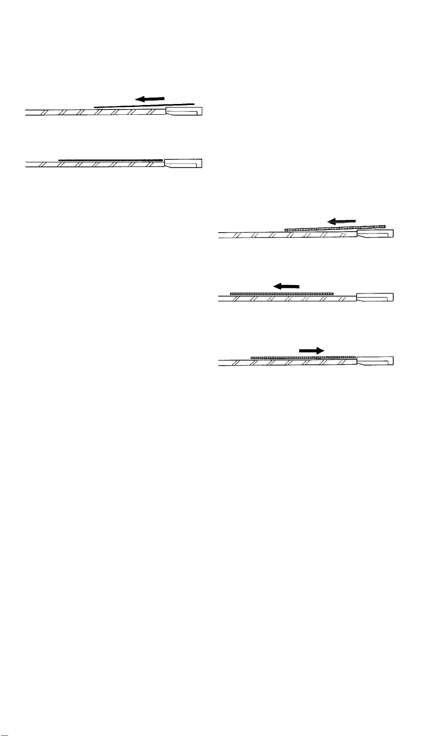
16.6 ORIGINAL POSITIONING
Thin Paper Mode
Thick Paper Mode
Customers can choose the paper transport mode by "User Tool" depending
on the thickness of the original used.
-- In thin paper mode --
The belt motor stops exactly when the trailing edge of the original passes the
right scale [A] edge. (The timing is measured by the timing sensor after
registration sensor is activated.)
-- In thick paper mode --
To correct skewing on the exposure glass, the original runs 10 mm after the
trailing edge passes the right scale. The belt motor then reverses and the
original travels until it meets the right scale.
If extremely thin paper is used in the thick paper mode, the paper may float
near the scale. This will result in poor image quality or original copy wrinkling.
The factory setting is "Thin Paper Mode:.
2-18
Page 30
5 June 1992 RDH
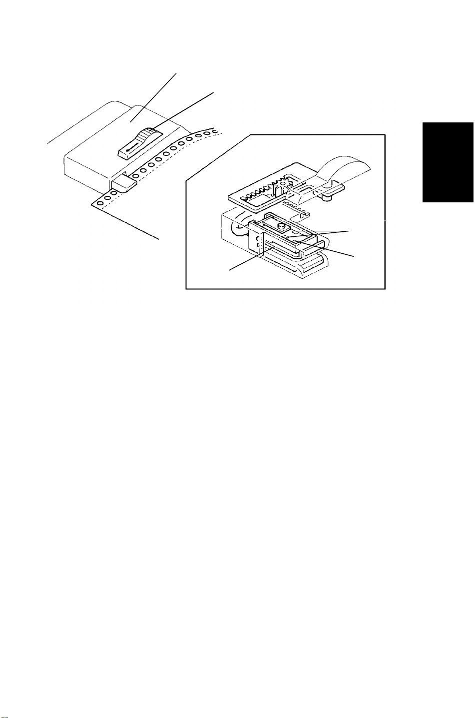
16.7 CFF Mode
[C]
[A]
Detailed
Descriptions
[E]
[D]
[B]
When the CFF guide lever [A] is slid to the left, the CFF sensor [B] comes out
of the single feed rear guide [C]. This sensor consists of one CFF set sensor
[D] and two CFF feed hole sensors [E]. The CFF set sensor [D] and two CFF
feed hole sensors [E]. The CFF set sensor detects if the computer form is set
in the CFF guide.
The CFF feed hole sensor counts the holes lined up to the computer form.
2-19
Page 31

SECTION 3
INSTALLATION
Page 32

5 June 1992 INSTALLATION REQUIREMENT
1. INSTALLATION REQUIREMENT
1.1 ENVIRONMENT
1. Temperature Range: 10°C to 30°C (50°F to 86°F)
2. Humidity Range: 15% to 90% RH
3. Ambient Illumination: Less than 1,500 lux (do not exposure to direct
sunlight)
4. Ventilation: Minimum space 20 m3. Room air should turn over
at least 30 m3/hr/person.
5. Ambient Dust: Less than 0.15 mg/m3 (4 x 10⁻⁶ oz/yd3)
6. If the machine location is air-conditioned or heated, place the machine:
a) where it will not be subjected to sudden temperature changes.
b) where it will not be directly exposed to cool air from an air-conditioner
in the summer.
Installation
c) where it will not be directly exposed to reflected heat from a space
heater in winter.
7. Avoid placing the machine in an area filled with corrosive gas.
8. Avoid any places higher than 2,000 meters (6,500 feet) above seal level.
9. Place the machine on a strong and level base.
10. Avoid any area where the machine may be frequently subjected to strong
vibration.
1.2 MACHINE LEVEL
1. Front to back level: within 5 mm (0.2")
2. Right to left level: within 5 mm (0.2")
3-1
Page 33

INSTALLATION REQUIREMENT 5 June 1992
1.3 MINIMUM SPACE REQUIREMENTS
More than 15.8"
(400 mm)
More than 11.8"
More than 11.8"
(300 mm)
More than 39.4"
(1000 mm)
(300 mm)
1.4 POWER REQUIREMENTS
1. Input voltage level:
120 V/60 Hz: More than 20 A (for U.S.A. version)
220 V/230 V/240 V/50 Hz: More than 10 A (for European version)
2. Permissible voltage fluctuation: ±10%
3. Do not set anything on the power cord.
NOTE: a) Make sure the plug is firmly inserted in the outlet.
b) Avoid multi-wiring.
3-2
Page 34

5 June 1992 ACCESSORY CHECK
2. ACCESSORY CHECK
Check the quantity and condition of the accessories in the box according to
the following list:
1. Operation Unit ................................................................1
2. Operation Unit Stand......................................................1
3. Fusing Unit Release Lever.............................................1
4. Key Counter Cover.........................................................1
5. Key Counter Bracket ......................................................1
6. Key Counter Plate Nut ...................................................1
7. Drum Guide ....................................................................1
8. Leveling Shoe.................................................................4
9. Operating Instructions Holder.........................................1
10. Editing Sheet..................................................................1
11. Sponge Cushion.............................................................1
12. Operating Instructions ...................................................1
13. Installation Procedure.....................................................1
14. NECR .............................................................................1
15. Envelop for NECR (-17 machine only)...........................1
16. User Survey Card (-17 machine only)............................1
17. M4 x 6 Screw..................................................................4
18. M5 x 8 Screw..................................................................4
19. M3 x 10 Screw................................................................2
20. M4 x 8 Screw..................................................................10
21. Harness Clamp...............................................................2
22. Bushing...........................................................................1
23. Operation Unit Stopper...................................................1
Installation
3-3
Page 35

INSTALLATION PROCEDURE 5 June 1992
3. INSTALLATION PROCEDURE
[A]
[D]
[A]
[C]
[B]
[F]
[E]
CAUTION: While the leveling shoes are not installed, do not
completely pull out many units simultaneously. Otherwise,
the machine could topple.
NOTE: Keep the shipping retainers after installing the machine. They will be
reused if in the future the machine is transported to another location.
Proper reinstallation of the shipping retainers is required in order to
avoid any transport damage.
1. Remove the strips of the filament tape [A] and remove the cushion [B] of
the exposure glass.
2. Open the left and right front doors [C, D] and remove the strips of filament
tape [E]. Remove the styrofoam block [F] under the transport unit.
3-4
Page 36

5 June 1992 INSTALLATION PROCEDURE
[D]
[E]
[A]
[B]
[F]
[C]
Installation
[G]
[H]
3. Remove the fusing cover [A] (3 screws), fixing bracket [B] (1 screw), and
reinstall the fusing cover. Install the fusing unit release lever [C], turn the
lever clockwise, and fix it (1 M5 x 8 screw).
4. Pull out the duplex unit [D], open the upper guide [E], and remove the
strip of the filament tape [F]. Reset the duplex unit.
NOTE: Do not pull duplex fork gate from positioning pin when removing
filament tape.
5. Remove the right cover [G] (2 screws) and 1 stud [H] securing the paper
tray. Reinstall the right cover.
3-5
Page 37

INSTALLATION PROCEDURE 5 June 1992
[D]
[M]
[A]
[B]
[I]
[K]
[E]
[C]
[H]
[F]
[G]
[J]
[L]
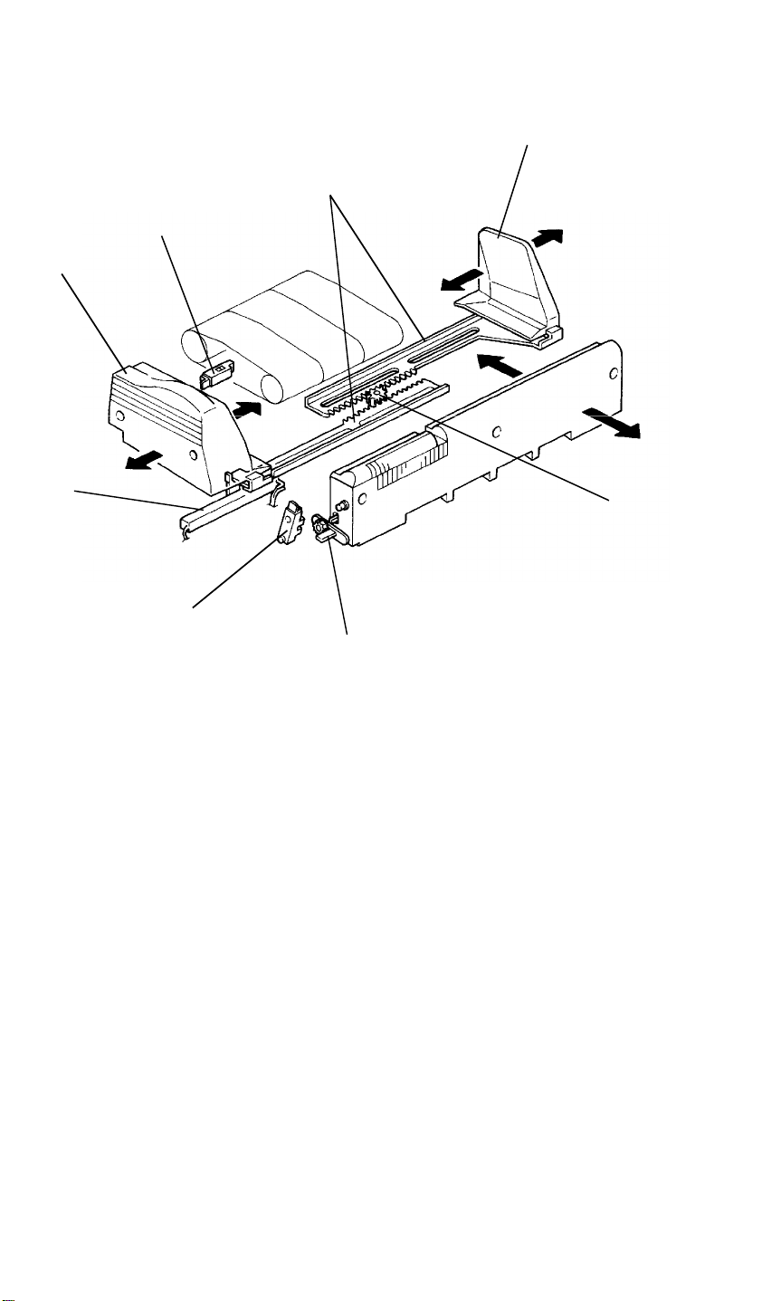
6. Remove the front scale holder [A] (2 screws), front scale [B] (2 screws),
exposure glass [C], left top cover [D] (7 screws), and right rear cover [E]
(front view, 2 screws).
7. Remove the 3rd scanner fixing bracket [F] (1 screw) and scanner fixing
screw [G].
NOTE: The scanner fixing screw is required when replacing the scanner
wire. Please keep it for future use.
8. Reinstall the exposure glass, front scale, front scale holder, and the left
top cover.
NOTE: • The mark [H] on the edge of the glass should face up. This
side is smoother and it generates less static electricity when
the DF is used.
• Use the flat head screw for 4 screws [I].
9. Remove the left inner cover [J] (4 screws), strip of filament tape [K]. Then,
remove the PTC unit [L], and the development unit [M] (1 screw and 1
connector).
3-6
Page 38

5 June 1992 INSTALLATION PROCEDURE
[B]
[A]
Installation
[F]
[H]
[I]
[D]
[C]
[J]
[G]
[E]
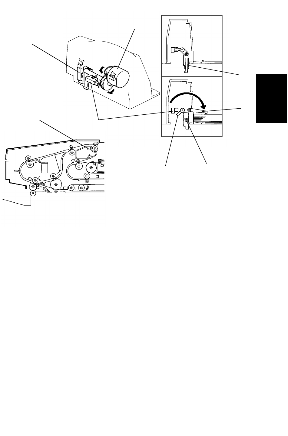
10. Remove the charge corona unit [A] (1 connector and 1 clamp) and erase
unit [B].
11. Lower the transport unit by the lever [C] as shown and remove the drum
stay [D] and cleaning unit [E].
12. Remove the drum potential sensor [F] (2 connectors), ID sensor [G], and
drum protection sleeve [H].
13. Reinstall all the units around the drum except for the development unit
and PTC unit.
NOTE: Press the drum shaft [I] to the left and align the cleaning unit to
the guides [J] to prevent the drum damage when reinstalling the
cleaning unit.
3-7
Page 39

INSTALLATION PROCEDURE 5 June 1992
[A]
14. Remove the development filter [A] from the development unit.
15. Pour the developer (1 bag: 1.7 kg) evenly between the left and right side
of the development unit and reinstall the development filter. Then,
reinstall the development unit (1 connector and 1 screw), and PTC unit on
the copier.
16. Load toner as follows (refer to the instruction decal):
a) Shake a new toner cartridge well while holding it horizontally.
b) Turn the green lever clockwise.
c) Insert the cartridge and return the green lever to the down position.
d) Cut the green tape.
e) Press down tab 1 and pull shutter 2 until you see the green tab 3.
f) Grasp tab 3 and pull the seal until you see the red line.
g) Push the shutter back in.
17. Install the left inner cover and set the transport unit.
3-8
Page 40

5 June 1992 INSTALLATION PROCEDURE
[B]
[E]
[F]
[C]
[D]
[A]
Installation
[G]
[H]
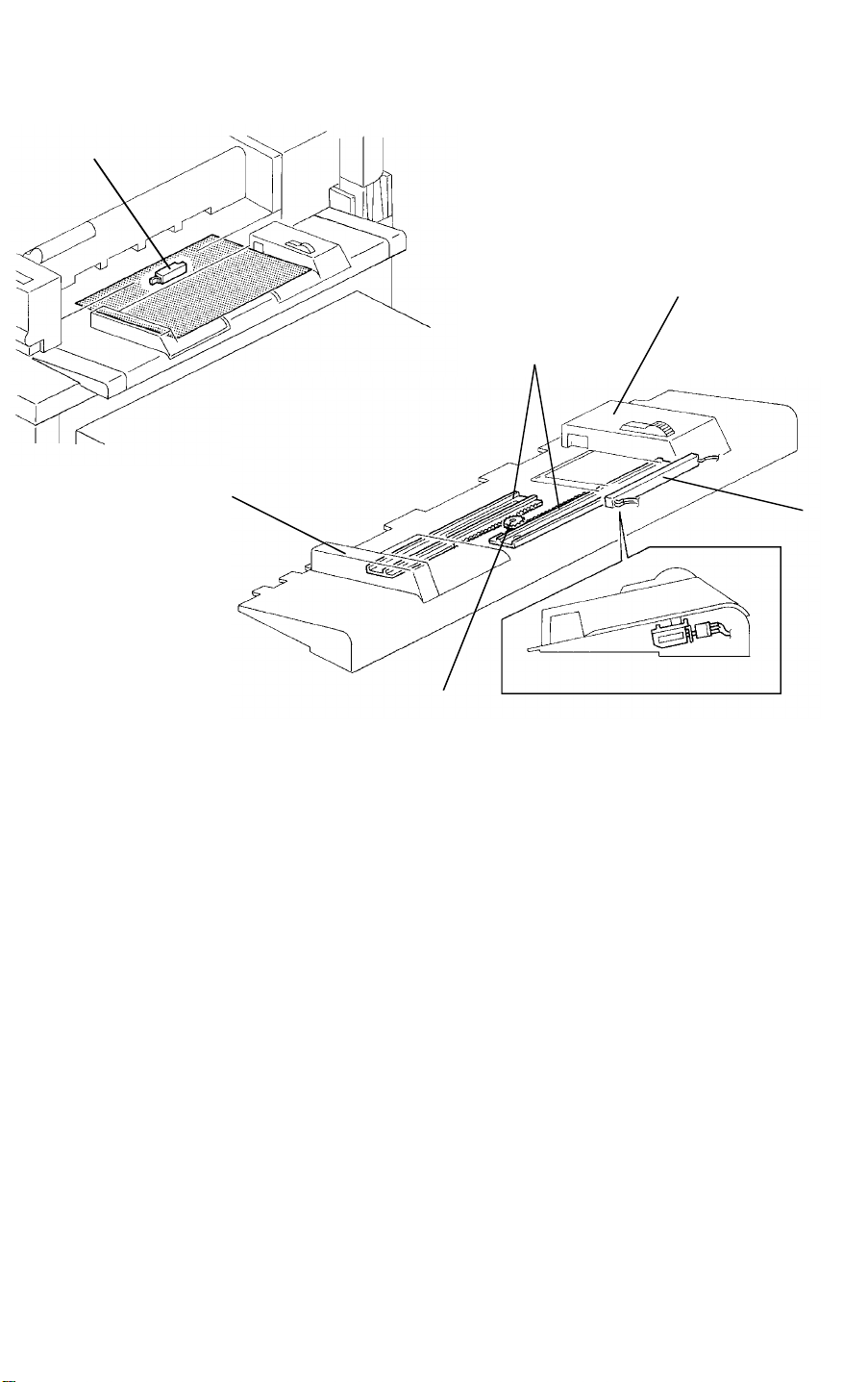
18. Connect the operation unit [A] to the operation unit stand [B] (4 screws
and 1 connector).
19. Install the operation unit (1 M5 x 8 screw [C] and 1 connector [D]) and the
operation unit stopper [E] (2 M5 x 8 screws). The oval hole [F] of the
operation unit stopper should be at the lower position.
NOTE: • 2 height positions of the operation unit can be selected by the
positions of securing screw [C].
• The operation unit can be moved left to right by removing one
M5 x 8 screw [C] when the operation unit is mounted at the
lower position.
20. Secure the grounding wire [G] of the operation unit (1 screw) and reinstall
the right rear cover.
21. Set the drum guide [H] to the lower inner cover.
3-9
Page 41

INSTALLATION PROCEDURE 5 June 1992
[C]
[A]
[C]
[B]
[F]
[H]
[G]
[D]
[E]
22. Insert the leveling shoes [A] under the feet, and level the machine by
securing down the feet.
23. Insert the sponge cushion [B].
24. Remove the strips of filament tape [C] of LCT.
25. Remove the LCT lower rear cover [D] (2 screws), fixing plate [E] (3
screws) and reinstall the LCT lower rear cover. Remove the LCT upper
rear cover [F] (4 screws), fixing screw [G], fixing plate [H] (2 screws), and
reinstall the LCT upper rear cover.
3-10
Page 42

Installation
5 June 1992 INSTALLATION PROCEDURE
[C]
[D]
[B]
[F]
[A]
[E]
26. Remove the copier left upper cover [A] (2 screws) and left lower cover [B]
(3 screws).
27. Cut 2 binds [C] for the LCT interface harness by the pliers.
28. Secure the ground wire [D] to the copier (1 screw).
29. 220/230/240 V version machines only
If the voltage of electrical power supply from wall outlets is 220 V or 240
V, change the voltage as follows:
a) Disconnect the input line [E] from the 230 V connector.
b) Disconnect the dummy connector [F] from the appropriate voltage (220
V or 240 V).
c) Connect the input line to the appropriate voltage (220 V or 240 V).
d) Connect the dummy connector to the 230 V connector.
3-11
Page 43

INSTALLATION PROCEDURE 5 June 1992
[F]
[B]
[E]
[C]
[D]
[H]
[G]
[F]
[A]
c
[I]
1
0
30. Pass 6 connectors of the interface harness [A] through the rear upper
hole [B] of the left lower cover and reinstall the left lower cover. Do not fix
the screw [C]. Set 6 connectors to the connectors of the LCT harness [D].
31. Mount the LCT unit on the copier (Insert the 2 mounting studs [E] into the
docking holes [F]).
32. Fix the LCT unit to the copier (1 screw).
33. Screw down the feet [G] to level the LCT so that the LCT is parallel to the
main copier (see illustration).
34. Guidance ROM Kit installation (-27 versions only). Remove the operation
unit rear cover [H] (4 screws) and install the appropriate ROMs [I] to the
operation unit board. Distinguish the chips (0, 1, and c) by the last 4 digits
of their part number. The lowest one is installed at 0, the middle one at 1,
the highest one at c.
35. Reinstall all the covers.
36. Install the copy tray or follow the finisher unit installation.
37. Plug in the power cord and turn on the main switch.
38. Check the copy quality and the copier operation.
3-12
Page 44

5 June 1992 INSTALLATION PROCEDURE
3.1 A3/11" x 17" COUNTER INSTALLATION
[A]
Installation
[B]
[C]
CAUTION: Unplug the copier power cord before starting the following
procedure.
1. Open the right front door and remove the right inner cover [A] (3 screws).
2. Install the A3/11" x 17" counter [B] (1 connector).
3. Cut the cap [C] of the right inner cover by the pliers.
4. Reassemble.
5. Plug in the copier power cord and turn on the main switch.
6. Set the A3/11" x 17" counter mode on by using SP mode.
7. Check the counter operation by making an A3/11" x 17" copy.
3-13
Page 45

INSTALLATION PROCEDURE 5 June 1992
3.2 KEY COUNTER HOLDER INSTALLATION
[I]
[C]
[B]
[J]
[E]
[D]
[A]
CAUTION: Unplug the copier power cord before starting the following
procedure.
[H]
[F]
[G]
1. Open the right front door and remove the right inner cover (3 screws).
2. Remove the dummy connector [A].
3. Remove the right cover [B] (2 screws) and small cap [C].
4. Connect the key counter holder [D] to key counter bracket [E] with key
counter plate nut [F] (2 screws).
5. Run the key counter harness [G] through the bushing [H] and right cover
hole [I] and fix the key counter harness (1 screw and 1 harness clamp).
6. Install the key counter bracket to the right cover (3 screws).
7. Set the key counter harness connector to the 4P connector from the
copier.
8. Reinstall the right cover.
9. Install the key counter cover [J] (2 screws).
10. Reassemble the machine.
3-14
Page 46

SECTION 4
SERVICE TABLES
Page 47

Service
Tables
5 June 1992 SERVICE REMARKS
1. SERVICE REMARKS
1.12 RDH
1. Take care not to damage the harnesses of the original table by pulling
roughly when you remove the original table.
2. Take care not to injure yourself by dropping the RDH unit when removing
it.
3. After replacing the RDH main PCB or RDH RAM board, perform the RDH
motor adjustment, RDH registration adjustment, and CFF registration
adjustment. (This allows the RDH to communicate with the copier main
PCB.)
1.13 FINISHER
1. Do not turn on the main switch while the shift tray is not installed. Both
the stack height sensor and the shift tray upper limit switch do not work
without the shift tray, and causes the tray lift mechanism broken.
2. Before removing the timing belts, mark the position of the tension
brackets.
4-1
Page 48

SERVICE PROGRAM MODE 5 June 1992
2. SERVICE PROGRAM MODE
2.2 SP MODE FUNCTION
1 Jam Counter
Location Code
A Third Tray
B Not used
C Not used
D Not used
E Horizontal Transport Unit
F Registration
G Paper Separation
H Fusing Unit
I Paper Exit
J Duplex Entrance
K Duplex Paper Feed
S First Tray
U Second Tray
R1 Finisher Entrance
R2 Finisher Exit
R3 Jogger Unit Entrance
R4 Jogger Unit
P1 RDH Feed-in
P2 RDH Transport Unit
P3 RDH Feed-out
NOTE: To clear counters, use SP mode (Counter Clear).
12
4-2
Page 49

Service
Tables
5 June 1992 SERVICE PROGRAM MODE
2 Daily / Weekly Jam Counter
Week 1 means first week of a month
Counters are not cleared at the end
of the week or month.
For example, if this menu is
displayed on Monday, the counters
of Tuesday through Friday is the
data of previous week.
NOTE: To clear counters, use SP mode (Counter Clear).
12
4-3
Page 50

SERVICE PROGRAM MODE 5 June 1992
3 Copy Counter
Test mode copy counter displays the
number of copies in SP Test Mode
8
.
This counter only counts up when
Test Copy Counter ON is
(SP mode PAGE 4).
10
Block copy counter displays the
number of copies after block copy
counter clear (SP mode
PAGE 1). Use this function when the
machine is connected to a Remote
Diagnostic System.
NOTE: 1. To clear counters, use SP mode Counter Clear).
12
2. The total number of copies can only be cleared by performing the
RAM clear.
SET
12
4-4
Page 51

Service
Tables
5 June 1992 SERVICE PROGRAM MODE
4 Daily / Weekly Copy Counter
NOTE: To clear counters, use SP mode (Counter Clear).
12
5 Operating Time
Display the total rotating time of the
main motor. Minutes are not
displayed.
NOTE: This counter is only cleared by RAM clear.
(Main board DIP SW #1: ON, #2: OFF)
4-5
Page 52

SERVICE PROGRAM MODE 5 June 1992
6 SC Counters
NOTE: To clear counters, use SP mode (Counter Clear).
12
4-6
Page 53

Service
Tables
5 June 1992 SERVICE PROGRAM MODE
6 SC Counters (continued)
NOTE: To clear counters, use SP mode (Counter Clear).
12
4-7
Page 54

SERVICE PROGRAM MODE 5 June 1992
7 Sensor Output
ID Sensor
ID sensor output for bare drum
Vsg
surface
Vsp ID sensor output for pattern
Drum Potential Sensor
Vd set up value during the process
Vd
control sequence
VL set up value during the process
VL1
control sequence
VL2 VL value during copy cycle
Residual voltage during the
Vr
process control sequence
Potential sensor output when 100V
V
100
applied to drum shaft
Potential sensor output when 800V
V
800
applied to drum shaft
Drum potential just after charging
V
during the process control
01
sequence
Drum potential just after charging
V
02
during copy cycle
ADS Sensor
ADS sensor output value during
Vs
the process control sequence
ADS sensor output value during
Vd
copy cycle
Paper Feed Time
Displays the interval between the
time a paper feed clutch turns on and
the time the registration sensor turns
on.
Reference Time (theoretical number
assuming no paper slippage)
(ms)
1st Tray 1,028
2nd Tray 730
3rd Tray 1,336
Duplex Tray 1,091
4-8
Page 55

Service
Tables
5 June 1992 SERVICE PROGRAM MODE
8 SP Test Mode -- 1 (PAGE 1 - 1)
Sensors
Turns on and off the 12-volt line of the dc drive board (CN302-2), which
applies power to sensors, and checks sensor operation. The sensors which
are normally activated during the stand-by condition cannot be checked
because sensor output does not change.
Touch on the display. The copier automatically checks sensors and
START
displays defective sensor code numbers (maximum 5 sensors).
Sensor Code Number
110 Paper Feed Sensor: 3rd tray
111 Upper Limit Sensor: 3rd tray
112 Lower Limit Sensor: 3rd tray
113 Paper End Sensor: 3rd tray
130 Paper Feed Sensor: 1st tray
131 Upper Limit Sensor: 1st tray
132 Lower Limit Sensor: 1st tray
133 Paper End Sensor: 1st tray
150 Paper Feed Sensor: 2nd tray
151 Upper Limit Sensor: 2nd tray
152 Lower Limit Sensor: 2nd tray
153 Paper End Sensor: 2nd tray
160 Paper Feed Sensor: duplex
163 Paper End Sensor: duplex
164 Pick-up Position Sensor: duplex
165 Duplex Entrance Sensor
400 Fusing Sensor
500 Exit Sensor
800 Toner Cartridge Sensor
4-9
Page 56

SERVICE PROGRAM MODE 5 June 1992
8 SP Test Mode -- 2 (PAGE 1 - 2)
Solenoids/Clutches
Turns on and off the 24-volt lines to solenoids and clutches from the main
board, and confirms component activity by checking electrical current value.
Touch on the display. The copier automatically checks components
START
and displays defective component code numbers (maximum 5 components).
Solenoid/Clutch Code Number
100 Pick-up SOL: 1st tray
104 Paper Feed MC: 1st tray
106 Registration MC
200 Pick-up SOL: 3rd tray
204 Paper Feed MC: 3rd tray
205 Vertical Drive MC
300 Pinch Roller SOL
301 Inverter Gate SOL
302 Junction Gate SOL
303 Duplex Stopper SOL
304 Duplex Paper Feed SOL
305 Positioning SOL
306 Fork Gate SOL 1
307 Fork Gate SOL 2
308 Pressure Plate SOL
408 Cleaning SOL
411 2nd Tray Lock SOL
500 Pick-up SOL: 2nd Tray
504 Paper Feed SOL: 2nd Tray
4-10
Page 57

Service
Tables
5 June 1992 SERVICE PROGRAM MODE
8 SP Test Mode -- 3 (PAGE 1 - 3)
Item Function Test Method
Charge Cleaner Turns on charge and T/S corona
wire cleaners. (one round)
ID Sensor Adjusts Vsg value automatically
and makes ID sensor pattern,
then checks Vsp value.
ADS Sensor Adjusts the ADS sensor
automatically and measures the
original background density.
Drum Potential
Sensor
Exposure Lamp Turns on the exposure lamps and
Applies 100 V and 800 V to the
drum drive shaft from the
development bais power pack and
measures V
measures lamp intensity sensor
value.
100 and V800 values.
Touch .
1. Touch on the display.
2. Press "Start" key top on the
Note: Test result is displayed in
Sensor Output (SP mode
).
1. Touch to turn on lamps.
2. Touch to turn off lamps.
Note: Test result is displayed in
Sensor Output (SP mode
).
START
SET
operation unit.
7
SET
RESET
7
4-11
Page 58

SERVICE PROGRAM MODE 5 June 1992
8 SP Test Mode -- 4 (PAGE 2)
Test Procedure
Touch on the display and press "START" key top to start.
Touch or press "CLEAR/STOP" key top to stop.
Drum Conditioning
Mode
Free Run Mode
(Lamp ON)
Free Run Mode
(Lamp OFF)
Scanner Free Run
Mode
RDH Free Run
Mode
CFF Free Run
Mode
Fusing Pressure
Check Mode
Finisher Motor
Test Mode
Finisher Free Run
Mode
SET
RESET
Item Function Remarks
Turns on the main motor, the
development drive motor, corona
power packs, and the erase lamp.
Operates the copier without
feeding paper.
Operates the copier without
feeding paper or turning on the
exposure lamp.
Runs the scanner unit.
Feeds originals automatically
without main copier operation.
Feeds CFFs automatically without
main copier operation.
During copy cycle, a copy stops in
the fusing unit for 15 seconds.
Operates the finisher drive motors
in sequence.
Operates the finisher without
feeding paper.
Place sheets of white paper (A3
or 11" x 17") on the exposure
glass.
Do not operate the machine in this
mode for a long time.
Before testing, set originals in the
original table. The test is done
when all originals are fed out.
Before testing, set CFFs in the
original table. The test is finished
when all CFFs are fed out.
Select a paper tray before
accessing the SP mode and open
document feeder to make sky
shot.
The transport drive, stack feed,
and exit drive motor speeds are
adjusted automatically.
4-12
Page 59

Service
Tables
5 June 1992 SERVICE PROGRAM MODE
8 SP Test Mode -- 5 (PAGE 3)
Test Procedure
Touch on the display and press "START" key top to start.
SET
Touch or press "CLEAR/STOP" key top to stop.
Cleaning Blade
OFF Mode
Process Control
Initial Setting
Toner Forced
Supply Mode
SC Detection OFF
Mode
Jam Detection
OFF Mode
Auto Drum Current
Adjustment Mode
RESET
Item Function Remarks
Turns off the cleaning blade. This mode is only effective during
SP mode condition.
Start the process control data
initialization.
Use free run mode (lamp on) at
the same time. Supplies toner at
the 30% setting.
Disables SC condition. This is
only effective during SP mode
condition.
Disables jam detection. This is
only effective during SP mode
condition.
Enable the adjustment of the T/S
and PTC power pack outputs
during process control initial
setting.
To avoid over-toning, stop
periodically (about 20 cycles) and
check copy quality.
Default: RESET
Use this function only after
replacing a power pack.
Otherwise, power pack outputs
may not set to the proper value.
4-13
Page 60

SERVICE PROGRAM MODE 5 June 1992
8 SP Test Mode -- 6 (PAGE 4)
1. Function
Turn on the individual power pack. Two or more power packs cannot be
turned on at the same time in this mode.
2. Test Procedure
Touch to turn on and touch to turn off.
SET
RESET
NOTE: This mode may damage a drum; so, use this only with an old drum.
3. Code Table
C Charge corona
T1 Transfer corona - first side
T2 Transfer corona - second side
PTC Pre-transfer corona
D1 Separation corona - first side
D2 Separation corona - second side
D3 Separation corona - leading edge
4-14
Page 61

Service
Tables
5 June 1992 SERVICE PROGRAM MODE
9 SP Adjustment -- 1 (PAGE 1 and 2)
Adjusts an output voltage from each
power pack. Output value changes
0.5% per step.
Note: This adjustment is only for
the test purpose. Do not use
this mode in the field.
C Charge corona
T1 Transfer corona - first side
T2 Transfer corona - second side
PTC Pre-transfer corona
D1 Separation corona - first side
D2 Separation corona - second side
D3 Separation corona - leading edge
Item Function Range
Separation
Corona ON
Timing Adj.
Leading Edge
Registration Adj.
Leading Edge
Erase Adj.
Fusing
Temperature Adj.
Exposure Lamp
Adj.
Front Staple
Position Adj.
Rear Staple
Position Adj.
Changes the ON timing of normal
separation corona after leading edge
separation.
Changes the ON timing of the
registration clutch.
Changes the ON timing of the image
erase after the leading edge erase.
Adjusts the hot roller temperature.
Use this mode with a thermometer.
Adjusts the light intensity of the
exposure lamp.
Adjusts the front staple position.
Adjusts the rear staple position.
Adjustment Standards
Leading Edge Registration
Leading Edge Erase
± 16
0 ~ 20
0
± 2 mm/0 ± 0.08" (Platen/Full Size)
4
± 3 mm/0.16" ± 0.12" (50 ~ 150%)
6
± 3 mm/0.24" ± 0.12" (151 ~ 200%)
Change/
Step
Approx.
2 mm
Approx.
1 mm
Approx.
1 mm
Approx.
1°C
1.3%
1 mm
1 mm
+
Delay ON
timing
Delay paper
feeding
Widen erase
width
Lower
temperature
Increase light
intensity
Move to rear
Move to front
4-15
Page 62

SERVICE PROGRAM MODE 5 June 1992
9 SP Adjustment -- 2 (PAGE 3)
Item Function Range
Horizontal Magnification
Adjustment (Full Size)
Horizontal Magnification
Adjustment (50%)
Horizontal Magnification
Adjustment (200%)
Focus Adjustment Adjusts the stop position of the
Vertical Magnification
Adjustment
Scanner Motor Gain
Adjustment
Adjusts the lens and the mirror unit
horizontal stop position at the full
size.
Adjusts the lens and mirror unit
horizontal stop position at 50%.
Adjusts the lens and the mirror unit
horizontal stop position at 200%.
mirror unit.
Adjusts the main motor speed.
(Effects all reproduction ratios.)
Factory use only.
Adjustment Standards
Magnification
Side to Side Registration
±0.5% (Full Size)
±1% (Enlarge/Reduction)
0
± 2 mm/0 ± 0.08" (Platen/Full Size)
± 16
± 3
± 16
Change/
Step
0.4 mm
0.3%
-- ----
+
Enlarge
side
4-16
Page 63

Service
Tables
5 June 1992 SERVICE PROGRAM MODE
9 SP Adjustment -- 3 (PAGE 4)
Item Function Test Procedure
RDH Motor
Adjustment
Item Function Range
RDH Registration
Adj.
CFF Registration
Adjustment
Adjusts the paper feed motor, transport
motor, and inverter motor speed of the
document feeder automatically.
Adjusts the original stop position.
Adjust the CF stop position.
± 16
Touch
START
Change/
Step
Moves
original
0.75 mm
away from
the right
scale.
+
Adjustment Standards
RDH Registration
CFF Registration
+4 mm
0
−2 mm
+3 mm
0
−1 mm
0
± 2 mm/0 ± 0.08" (2nd ~ Last-1)
⁄
⁄
0
0
+0.16′′
(Thin mode)
−0.08′′
+0.12′′
(Thick mode)
−0.04′′
4-17
Page 64

SERVICE PROGRAM MODE 5 June 1992
10 SP Special Feature -- 1 (PAGE 1 and 2)
<PAGE 1>
Item Function Setting Default
Fusing Lower
Temperature
Limit: High
Mode
A3/11 x 17
Counter ON
Mode
Select lower limit
temperature to
enter idling.
Increment option
counter when A3 or
11" x 17" copy is
made.
RESET
SET
RESET
SET
159°C (Cover Mode - 169°C) -- LT
169°C (Cover Mode - 169°C) -- A4
169°C (Cover Mode - 189°C) -- LT
174°C (Cover Mode - 189°C) -- A4
Optional counter not connected.
Optional counter connected.
RESET
RESET
NOTE: When the high temperature mode in the user tool is set, the lower
limit temperature is increased by as follows:
LT version: +20°C
A4 version: +15°C
SC Telephone No.
1. Touch .
SC Telephone No.
2. Enter numbers by pressing number key tops.
(Touch for hyphen)
3. Touch .
--
SC Telephone No.
Serial No.
1. Touch .
Serial No.
2. Enter the machine serial number by pressing number key tops.
3. Touch .
Serial No.
<PAGE 2>
Item Function Default Remarks
Tray Priority Select feed station at power
on or after reset.
No Select
Select 2nd tray at .
No Select
4-18
Page 65

Service
Tables
5 June 1992 SERVICE PROGRAM MODE
10 SP Special Feature -- 2 (PAGE 3)
Item Function Setting Default
Process Control
OFF Mode
Fusing Idling
Mode
Disable the process control. Enable
Rotates the main motor and
development motor for
approximately 20 minutes after
warm up.
RESET
SET
RESET
SET
Disable
No
Yes
RESET
RESET
Toner Density
Selection
Toner Supply
Amount
ID Selection in
ADS Mode
Copy Counter
Up/Down Mode
A3/11 x 17
Double Count
Selects a voltage shift for ID sensor
bias.
Selects how much toner is supplied
in detect mode.
Selects a voltage shift of the
development bias in ADS Mode.
Selects count up or down. Count up
Counts twice when A3 or 11" x 17"
copy is made.
LOW
NORMAL
HIGH
VHIGH
LOW
NORMAL
HIGH
VHIGH
RESET
SET
RESET
SET
--60 V
0 V
+60 V
+120 V
+60 V
0 V
--60 V
--120 V
Count down
Count once
Count twice
HIGH
30%
NORMAL
RESET
RESET
4-19
Page 66

SERVICE PROGRAM MODE 5 June 1992
10 SP Special Feature -- 3 (PAGE 4)
Item Function Setting Default
Magnification
Ratio Priority
Selects the magnification when
is selected.
Reduce/Enlarge
0.93
Manual ID
Level Selection
Select Tray
Display in APS
Copy Disable
Mode
Test Copy
Counter ON
Selects ID level when Auto Image
Density is changed to Manual Image
Density.
Displays copy trays in APS mode. No
Turns the print key red and disables
copying.
Count copy quantity in SP test mode. Counter OFF
RESET
SET
RESET
SET
RESET
SET
RESET
SET
Center
Preset level
Yes
No
Yes
Counter ON
RESET
RESET
RESET
RESET
4-20
Page 67

Service
Tables
5 June 1992 SERVICE PROGRAM MODE
10 SP Special Feature -- 4 (PAGE 5)
Item Function Setting Default
Copy Number
to Release
Blade Pressure
Data Print I Prints out logging data of
Data Print II Prints out logging data of
Enable Auto
Reset Function
at Key Counter
Removal
Selects the blade release
timing after copying jobs.
SP modes 1 to 6.
SP modes 7 to 11.
Automatically resets when
key counter is removed.
RESET
SET
Communication Configuration:
Mode: Asynchronous
Data format: Start bits: 1
Parity check: Even parity
Transmission speed: 1200 bps
Connector type:
25-pin female connector
RESET
SET
15 seconds (100
copies or more)
5 minutes (less
than 100 copies)
15 seconds (250
copies or more)
5 minutes (less
than 250 copies)
Stop bits: 1
Data bits: 7
Disable
Enable
RESET
RESET
Connector for printer
Copier Printer RS232C
Pin No. Signal Pin No. Signal
1 FG 1 FG
2 TXD 3 RXD
3 RXD -- -4 CTS -- -5 RTS -- -7 SG 7 SG
4-21
Page 68

SERVICE PROGRAM MODE 5 June 1992
11 Alarm Level Setting
Item Function Setting Default
Sensor Alarm
Level
Jam Alarm Level Select jam ratio for one week to
SC Alarm Level Select SC occurrence ratio for
PM Alarm Set Set PM interval to start RDS PM
Block Alarm Set Set copy quantity to start RDS
Set the output level of electrical
volume (sensor) against full
value (100%) to start RDS alarm
call.
Output of each sensor in normal
condition is designed to 50%.
start RDS alarm call.
one week to start RDS alarm
call.
alarm call.
block alarm call.
LEVEL 1
LEVEL 2
LEVEL 3
LEVEL 1
LEVEL 2
LEVEL 3
1/10,000 copies
1/5,000 copies
1/2,500 copies
1/50,000 copies
1/25,000 copies
1/10,000 copies
90
LEVEL 2
LEVEL 2
150
4-22
Page 69

Service
Tables
5 June 1992 SERVICE PROGRAM MODE
12 Counter Clear
Clear
YES
NO
1. Touch beside the counter you wish to clear.
2. Touch to clear the counter.
Clear
Yes
4-23
Page 70

SERVICE PROGRAM MODE 5 June 1992
2.3 SP MODE INDEX
Item
SP Menu
No. Page
Manual
Page
A3/11x17 counter on mode 10 1 4-18
A3/11x17 double count 10 3 4-19
ADS sensor output 7 1 4-8
ADS sensor test 8 1 4-11
Alarm level setting 11 1 4-22
All counters clear 12 1 4-23
Auto drum current adjustment mode 8 3 4-13
Auto reset function at key counter removal 10 5 4-21
Block alarm set 11 2 4-22
Block copy counter 3 2 4-4
Block copy counter clear 12 1 4-23
CFF free run mode 8 2 4-12
CFF original counter 3 2 4-4
CFF registration adjustment 9 4 4-17
Charge cleaner Test 8 1 4-11
Cleaning blade off mode 8 3 4-13
Clutch test 8 1 4-10
Copier jam counter clear 12 1 4-23
Copier operating time 5 1 4-5
Copy counter 3 1 4-4
Copy counter clear 12 1 4-23
Copy counter up/down mode 10 3 4-19
Copy disable mode 10 4 4-20
Copy number to release blade pressure 10 5 4-21
Counter clear 12 1 4-23
Daily copier jam counter 2 1 4-3
Daily copy counter 4 1 4-5
Daily original jam counter 2 2 4-3
Daily peripheral jam counter 2 3 4-3
Daily SC counter 6 8 4-7
4-24
Page 71

Service
Tables
5 June 1992 SERVICE PROGRAM MODE
Item
SP Menu
No. Page
Manual
Page
Data print 10 5 4-21
Drum conditioning mode 8 2 4-12
Drum potential sensor output 7 1 4-8
Drum potential sensor test 8 1 4-11
Drum temperature 7 1 4-8
Duplex mode copy counter 3 2 4-4
Enable auto reset function at key counter removal 10 5 4-21
Exposure lamp adjustment 9 2 4-15
Exposure lamp heater temperature 7 1 4-8
Exposure lamp on check 8 1 4-11
Exposure sensor output 7 1 4-8
Finisher free run mode 8 2 4-12
Finisher motor test mode 8 2 4-12
Focus adjusment 9 3 4-16
Free run mode - CFF 8 2 4-12
Free run mode (lamp OFF) 8 2 4-12
Free run mode (lamp ON) 8 2 4-12
Free run mode - scanner 8 2 4-12
Front staple position adjustment 9 2 4-15
Fusing idling mode 10 3 4-19
Fusing lower temperature limit: high mode 10 1 4-18
Fusing pressure check mode 8 2 4-12
Fusing temperature 7 1 4-8
Fusing temperature adjustment 9 2 4-15
Horizontal magnification adjustment (200%) 9 3 4-16
Horizontal magnification adjustment (50%) 9 3 4-16
Horizontal magnification adjustment (full size) 9 3 4-16
ID selection in ADS mode 10 3 4-19
ID sensor output 7 1 4-8
ID sensor test 8 1 4-11
Jam alarm level 11 1 4-22
4-25
Page 72

SERVICE PROGRAM MODE 5 June 1992
Item
SP Menu
No. Page
Manual
Page
Jam counter - Location 1 2 4-2
Jam counter - Original location 1 3 4-2
Jam counter - Original total 1 3 4-2
Jam counter - Paper Size 1 1 4-2
Jam counter - Total 1 1 4-2
Jam detection off mode 8 3 4-13
Leading edge erase adjustment 9 2 4-15
Leading edge registration adjustment 9 2 4-15
Magnification ratio priority 10 4 4-20
Manual ID level selection 10 4 4-20
Operating time 5 1 4-5
Original counter clear 12 1 4-23
Original jam counter clear 12 1 4-23
Paper feed time 7 2 4-8
Paper tray copy counter 3 2 4-4
PM alarm set 11 2 4-22
PM counter clear 12 1 4-23
PM cycle copy counter 3 2 4-4
Power pack output adjustment 9 1 4-15
Power pack output on mode 8 4 4-14
Process control initial setting 8 3 4-13
Process control off mode 10 3 4-19
RDH free run mode 8 2 4-12
RDH motor adjustment 9 4 4-17
RDH original counter 3 2 4-4
RDH registration adjustment 9 4 4-17
Rear staple position adjustment 9 2 4-15
SC alarm level 11 1 4-22
SC counter - ADS 6 2 4-6
SC counter - Counter 6 7 4-7
SC counter - Development 6 3 4-6
4-26
Page 73

Service
Tables
5 June 1992 SERVICE PROGRAM MODE
Item
SP Menu
No. Page
Manual
Page
SC counter - Drum charge 6 2 4-6
SC counter - Drum discharge 6 3 4-6
SC counter - Drum potential 6 2 4-6
SC counter - Duplex 6 5 4-6
SC counter - Exposure 6 1 4-6
SC counter - Fan motor 6 4 4-6
SC counter - Finisher 6 7 4-7
SC counter - Fusing 6 6 4-6
SC counter - ID sensor 6 2 4-6
SC counter - Image transfer 6 3 4-6
SC counter - Magnification 6 1 4-6
SC counter - Paper feed 6 5 4-6
SC counter - RDH 6 6 4-6
SC counter - Scanner 6 1 4-6
SC counter - Se-drum 6 4 4-6
SC counter - Separation 6 3 4-6
SC counter - total 6 8 4-7
SC counter clear 12 1 4-23
SC detection off mode 8 3 4-13
SC telephone No. 10 1 4-17
Scanner free run mode 8 2 4-12
Scanner motor gain adjustment 9 3 4-16
Select tray display in APS 10 4 4-20
Sensor alarm level 11 1 4-22
Sensor output 7 1 4-8
Sensors test 8 1 4-9
Separation corona on timing adjustment 9 2 4-15
Serial No. 10 1 4-18
Side to side registration adjustment 9 3 4-16
Solenoid test 8 1 4-10
SP adjustment 9 1 4-15
4-27
Page 74

SERVICE PROGRAM MODE 5 June 1992
Item
SP Menu
No. Page
Manual
Page
SP special features 10 1 4-18
SP test mode 8 1 4-9
Staple position adjustment - front 9 2 4-15
Staple position adjustment - rear 9 2 4-15
Test copy counter clear 12 1 4-23
Test copy counter on 10 4 4-20
Test mode copy counter 3 2 4-4
Toner density selection 10 3 4-19
Toner forced supply mode 8 3 4-13
Toner supply amount 10 3 4-19
Total copies by paper size 3 1 4-4
Total number of copies 3 1 4-4
Total number of SC 6 8 4-7
Total original jams 1 3 4-2
Total paper jams 1 1 4-2
Tray priority 10 2 4-18
User codes/counters clear 12 1 4-23
Vertical magnification adjustment 9 3 4-16
Weekly copier jam counter 2 1 4-3
Weekly copy counter 4 1 4-5
Weekly original jam counter 2 2 4-3
Weekly peripheral jam counter 2 3 4-3
Weekly SC counter 6 8 4-7
4-28
Page 75

Service
Tables
5 June 1992 DIP SW TABLE
3. DIP SW TABLE
3.3 RDH MAIN CONTROL PCB
DIP 100
1 2 3 4
ON OFF OFF ON Free Run (SW100 - Start/SW101 - Stop)
ON ON OFF ON Motor Test (use DIP101 to turn on)
DIP101 Motor
1 Feed Motor
2 Belt Drive Motor
3 Inverter Motor
4 Blower Motor
Function
3.4 RDH LEDs
LED No. Lights when the following sensor is activated.
100 Original set sensor
101 Separator HP sensor
102 Entrance sensor
103 1st transport sensor
104 2nd transport sensor
105 Registration sensor
106 1st inverter sensor
107 2nd inverter sensor
108 Exit sensor
109 Single feed set sensor
110 Single feed exit sensor
111 Inverter entrance sensor
112 Original length sensor
113 Separator sensor
114 Lift sensor
115 Inverter unit cover switch
116 Motor speed -- Middle
117 Motor speed -- High
118 Motor speed -- Low
120 Original height sensor
4-29
Page 76

PREVENTIVE MAINTENANCE SCHEDULE 5 June 1992
4. PREVENTIVE MAINTENANCE SCHEDULE
4.1 PM TABLE
NOTE: The amounts mentioned in the PM interval are copy numbers.
C: Clean R: Replace L: Lubricate I: Inspect A: Adjustment
EM 150K 300K 450K 600K NOTE
OPTICS
Mirrors, Lens,
Reflector
1st and 2nd Scanner
Guides
Exposure Glass
C C C C C
Fiber Optics Cable
Exposure Flat Cable I I I I Replace at 3M
Exposure Lamp I I I I Replace at 900K
Optics Cooling Fan
Filter
Mirror Unit Guide Rod
Felt
Lens Horizontal Drive
Gear
Lens Guide Rod C C C C Dry cloth
L
L
C C C C
C C C C
C C C C
I, C I, C I, C I, C
Soft cloth
Dry cloth
Water
Replace after 1M originals
feed
Dry cloth
Replace at 3M
Remove dust
Replace if necessary
Launa oil; if it’s dry
Mobil Temp 78; if it’s dry
PAPER FEED (for each paper feed station)
Pick-up Rollers R R R R Copy numbers are for each
Paper Feed Rollers R R R R
Separation Roller
Paper Feed Sensors C C C C Blower brush
Paper Feed Guides C C C C Dry cloth
Relay Rollers C C C C Water
Tray Drive Worm
Gears
Drive Gears L Mobil Temp 78; if it’s dry
2nd Tray Drive Chain A Adjust chain tension
Registration Roller C Water
Paper Dust Cleaning
Roller
Paper Dust Pan Replace at 1.2M
Transport Belt/Unit C C C C Water
AROUND THE DRUM
L
R R R R
paper feed station. Replace
the rollers as a set.
Mobil Temp 78; if it’s dry
Replace at 1.2M
4-30
Page 77

Service
Tables
5 June 1992 PREVENTIVE MAINTENANCE SCHEDULE
EM 150K 300K 450K 600K NOTE
Drum C C C C Water/Dry cloth
Corona Wires R R R R
Wire Cleaner Pads R R R R
Toner Filter R R R R
Ozone Filter Replace at 1.2M
Corona Casing C C C C Water/Alcohol
Potential Sensor and
Drum Thermistor
Charge Corona Unit
Brush Seal
Erase Lamp C C C C Water
ID Sensor C C C C Water
QL Filter C C C C Water
Pick-off Pawls C C C C Alcohol
CLEANING UNIT
Cleaning Blade R R R R Apply setting powder
Flick Blade R R R R Apply setting powder
Cleaning Brush R R R R
Entrance Seal I, C I, C I, C I, C
Side Seals I, C I, C I, C I, C Replace if damaged
Cleaning Filter I, C I, C I, C I, C Replace if damaged
Cleaning Unit Inside C C C C Remove toner
C C C C
C C C C
Dry cloth/Blower brush
DEVELOPMENT UNIT
Developer R R
Upper Seal C C C C
Side Seals I I I R
Toner Cartridge Seals I I I I Replace if necessary
Sleeve Drive Gears C C C R Do not use any grease
Timing Belt Pulley C C C C
Toner Near End
Sensor Feeler
Development Filter R R R R
Development Duct
Filter
FUSING UNIT
Hot Roller R R
Hot Roller Bushing I R I R
Hot Roller Bearing I R I R
Pressure Roller R
Pressure Roller
Bushing
I I I I
R R R R
I I I R
Check movement
4-31
Page 78

PREVENTIVE MAINTENANCE SCHEDULE 5 June 1992
EM 150K 300K 450K 600K NOTE
Pressure Roller
Bearing
I I I R
Oil Supply Roller R R R R
Oil Supply Roller
Bushing
Stripper Pawls
C C C C
I, C I, C I, C I, C
Suitable solvent
Suitable solvent
Replace if damaged
Fusing Drive Gears L Mobil Temp 78
Guide Plates C C C C Suitable solvent
De-curling Belt C C C C Alcohol
De-curling Roller C C C C Suitable solvent
Fusing Transport
Rollers
C C C C
Suitable solvent (Resin rollers)
Alcohol (Rubber rollers)
DUPLEX (for duplex copies)
Pick-up Roller C R C R Clean with water
Paper Feed Roller R R R R Replace as a set
Separation Roller R R R R
Anti-static Brushes C C C C
RDH (for original)
Feed-in Belts C Alcohol
Transport Belt C C C R Alcohol or belt cleaner
Sensor Pads C C C C Blower brush
Feed and Transport
Rollers
Inverter and Exit
Rollers
C
C
Alcohol
Alcohol
Right Turn Rollers C Alcohol
4-32
Page 79

Service
Tables
5 June 1992 PREVENTIVE MAINTENANCE SCHEDULE
4.2 REGULAR PM SCHEDULE
1. Make A Copy and Remove the Developer (every 150K)
1. Make a copy of OS-UA3 test chart at manual image density level 4.
2. Remove the developer.
3. Unplug the copier and 2nd sorter stapler.
2. Optics (every 150K)
1. Clean the mirrors, lens, and reflector by using a soft cloth.
2. Clean the exposure glass with water.
3. Clean 1st and 2nd scanner guides with a dry cloth.
4. Clean the lens guide rods with a dry cloth.
5. Clean the fiber optics cable ends with dry cloth.
6. Clean the optics cooling fan filter. Replace it if necessary.
7. Inspect the exposure flat cable if there is any damage.
8. Inspect the exposure lamp if it has dark spots.
Every 900K
1. Replace the exposure lamp.
Every 3M
1. Replace the fiber optics cable and the flat cable.
Every 1M originals
1. Replace the exposure glass.
3. Paper Feed (every 150K for each feed station)
1. Clean the paper feed sensor of each feed station using a dry cloth
or a blower brush.
2. Clean the paper feed guide of each feed station using a dry cloth.
3. Clean the relay rollers, the transport belts, and the transport unit
using water.
4. Replace the pick-up, paper feed, and separation rollers of each
feed station.
4-33
Page 80

PREVENTIVE MAINTENANCE SCHEDULE 5 June 1992
Every 600K
1. Clean the registration roller using water.
2. Adjust the 2nd tray drive chain tension.
Every 1.2M
1. Replace the paper dust cleaning roller and the dust pan.
4. Duplex Unit (every 150K duplex copies)
1. Clean the pick-up roller using water.
2. Clean the anti-static brushes.
3. Replace the paper feed and separation rollers.
Every 300K duplex copies
1. Replace the pick-up roller.
5. RDH (every 150K originals)
1. Clean the sensor pads using the blower brush.
2. Clean the transport belt using the belt cleaner or alcohol.
Every 600K originals
1. Replace the transport belt.
2. Clean the feed-in belt, feed rollers, transport rollers, inverter
rollers, and exit rollers using alcohol.
6. Around The Drum (every 150K)
1. Clean the casing of the charge, T & S, and Pre-transfer corona
units. Use water first and then use alcohol.
2. Replace the corona wires and the wire cleaner pads.
3. Clean the charge corona unit brush seal.
4. Replace the toner filter.
5. Clean the drum potential sensor and the drum thermistor using a
dry cloth or blower brush.
6. Clean the erase lamp, the QL filter, and the ID sensor using water.
4-34
Page 81

Service
Tables
5 June 1992 PREVENTIVE MAINTENANCE SCHEDULE
7. Clean the pick-off pawls with alcohol.
8. Clean the drum surface using water. Then, use dry cloth.
Every 1.2M
1. Replace the ozone filter.
7. Cleaning Unit (every 150K)
1. Clean the unit inside.
2. Clean and inspect the entrance seal, the side seals, and the
cleaning filter.
3. Replace the cleaning blade, the flick blade, and the cleaning brush.
8. Development Unit (every 150K)
1. Clean the upper seal, the sleeve drive gear, and the timing belt
pulley.
2. Inspect the toner cartridge seals, the sleeve side seals, and toner
near end sensor feeler movement.
3. Replace the development filter, and the duct filter.
Every 300K
1. Replace the developer.
Every 300K
1. Replace the sleeve side seals and the sleeve drive gears.
9. Fusing Unit (every 150K)
1. Inspect the bushings and bearings for the hot and pressure rollers.
2. Inspect and clean the stripper pawls using a suitable solvent.
3. Clean the guide plates, the de-curling roller, and resin transport
rollers using a suitable solvent.
4. Clean the de-curing belt and the rubber transport rollers using
alcohol.
5. Clean the oil supply roller bushings using the suitable solvent.
6. Replace the oil supply roller.
4-35
Page 82

PREVENTIVE MAINTENANCE SCHEDULE 5 June 1992
Every 300K
1. Replace the hot roller together with the bushings and the
bearings.
Every 600K
1. Replace the pressure roller together with the bushings and the
bearings.
4-36
Page 83

SECTION 5
REPLACEMENT
AND
ADJUSTMENT
Page 84

5 June 1992 RDH
13. RDH
13.1 TRANSPORT BELT REPLACEMENT
[B]
[H]
[E]
[A]
[C]
[F]
1. Release the belt unit [A] by sliding the belt release lever [B] to the right.
2. Loosen the screw [C] and slide the lever [D] supporting the left transport
belt unit [E] to the right.
3. Remove the support guide plate [F] (2 screws).
4. Fold down the transport belt to the release position, and replace the
transport belt [G].
NOTE: When replacing the transport belt, make sure the transport belt is
positioned under the ribs [H].
[D]
[H]
[G]
Adjustment
Replacement
5-1
Page 85

RDH 5 June 1992
13.2 FEED-IN BELT REPLACEMENT
[G]
[H]
[F]
[A]
[B]
[E]
[D]
[J]
[I]
[C]
[G]
NOTE: Take care not to damage the harnesses [A] of the original table by
pulling roughly.
The side-to-side registration of the paper stack mode is required
after removing and reinstalling the original table. Before removing,
mark the position of the original table position to allow easier
reassembling.
1. Remove the RDH front cover [B] (6 screws).
2. Disconnect the 3 connectors [C] and remove the original table [D] (4
screws), otherwise the harnesses could be damaged.
3. Disconnect the drive shaft joint [E] (2 allen screws).
4. Remove the feed-in belt unit [F] (4 screws and 2 connectors [G]).
5. Replace the feed-in belts [H].
NOTE: • The shiny side of the feed-in belts should face out.
• When reassembling, pass the 3p connector through the hole [I]
and the 6p and 9p connectors through the slit [J].
5-2
Page 86

5 June 1992 RDH
13.3 SIDE-TO-SIDE REGISTRATION ADJUSTMENT
[A]
1. Set an original on the original table and make a copy in the stack feed
mode.
2. Measure the difference of the side-to-side registration between the copy
and original.
3. If the value does not match the standard, loosen the 4 screws [A] to
change the original table position. Then, tighten the screws.
4. Make continuous copies to check the variation. If the variation does not
match the standard, repeat the above step.
Adjustment
Replacement
5-3
Page 87

RDH 5 June 1992
13.4 ORIGINAL HEIGHT SENSOR POSITION ADJUSTMENT
Adjustment standard: LED120 20 sheets on, 10 sheets off
[A]
[B]
1. Remove the RDH rear cover and front side fence [A] (2 screws).
2. Loosen the screw [B] and adjust the height of the original height sensor
so that LED 120 on the RDH main control PCB turns on when 20 sheets
of paper is placed, and turns off when 10 sheets of paper is placed, on
the original table.
5-4
Page 88

5 June 1992 RDH
13.5 RDH UNIT REMOVAL
[E]
[B]
[D]
[F]
[F]
[C]
[A]
CAUTION: Take care not to injure yourself by dropping the RDH unit
during this procedure.
1. Remove the copier left rear and right rear covers.
2. Remove the upper rear cover [A] (3 screws) and rear cover [B] (1 screw)
of single feed table.
3. Remove the RDH unit stoppers [C] (3 screws each).
4. Remove the screw [D] connecting the ground wire.
5. Remove the RDH unit [E] (8 screws and 4 connectors [F]).
Adjustment
Replacement
5-5
Page 89

RDH 5 June 1992
13.6 SINGLE FEED TABLE REMOVAL
[A]
[B]
[C]
1. Remove the front [A] and rear [B] single feed table covers (1 screw each).
2. Remove the single feed table [C] (3 screws and 2 connectors).
5-6
Page 90

5 June 1992 RDH
13.7 SINGLE FEED SET SENSOR AND REGISTRATION
SENSOR REPLACEMENT
[D]
[A]
[C]
[B]
13.7.1 Preparation
1. Remove the front cover and rear cover [A] (8 screws).
2. Loosen the screw [B] from the original length sensor bracket [C].
3. Remove the original end fence unit [D] (8 screws).
Adjustment
Replacement
5-7
Page 91

RDH 5 June 1992
[D]
[C]
[B]
[E]
[A]
[G]
[F]
[E]
[H]
13.7.2 Single Feed Set Sensor Replacement
1. Remove the scale [A] (4 screws and 1 connector).
2. Replace the single feed set sensor [B] (1 screw).
13.7.3 Registration Sensor Replacement
1. Remove the right stay supporter [C] and right turn guide [D] (4 screws
each).
2. Remove the 5 screws [E] from the registration right guide [F] and release
the belt unit [G]. Then, slide the registration right guide to the left.
3. Replace the registration sensor [H] (1 screw and 1 connector).
5-8
Page 92

5 June 1992 RDH
13.8 VACUUM SHUTTER SOLENOID ADJUSTMENT
0.5 mm
[A]
[B]
[C]
1. Remove the feed-in belt unit.
2. Loosen the 2 screws [A].
3. Maintain the 0.5 mm gap (as shown) and adjust the solenoid bracket
position so that the shutter [B] closes completely when the plunger [C] is
pushed in the solenoid. Then, re-tighten the 2 screws.
Adjustment
Replacement
5-9
Page 93

RDH 5 June 1992
13.9 EXIT ROLLER SOLENOID ADJUSTMENT
[A]
[B]
[C]
[D]
0.5 mm
1. Remove the front cover.
2. Loosen the 2 screws [A].
3. Maintain the 0.5 mm gap (as shown) and adjust the solenoid bracket
position so that the arm [B] is parallel to the bracket [C] when the plunger
[D] is pushed in the solenoid. Then, re-tighten the 2 screws.
5-10
Page 94

5 June 1992 RDH
13.10 INVERTER BLOWER MOTOR BELT TENSION
ADJUSTMENT
Adjustment standard: 450 ± 50 g
450 ± 50 g
[A]
1. Remove the RDH rear cover.
2. Loosen the screw [A] from belt tightener.
3. Adjust belt tightener using a tension gauge as shown.
5-11
Adjustment
Replacement
Page 95

RDH 5 June 1992
13.11 BELT DRIVE, FEED, AND INVERTER BLOWER MOTOR
TENSION ADJUSTMENT
Adjustment standard: 750 ± 50 g
[A]
[A]
1. Loosen the 4 screws [A] from each motor bracket.
2. Adjust motor tension using a tension gauge as shown.
5-12
Page 96

SECTION 6
TROUBLESHOOTING
Page 97

5 June 1992 SYSTEM ERROR AND SERVICE CALL CONDITIONS
1. SYSTEM ERROR AND SERVICE CALL
CONDITIONS
SC700 - RDH Feed Motor Overload
Definition:
The RDH main control PCB cannot detect any pulses from the feed motor
encoder within 50 msec after the feed motor is activated.
Points to check:
• Mechanical interference with the feed motor
• Feed motor
• Fuse 102 on the RDH main control PCB
• RDH main control PCB
SC701 - RDH Belt Drive Motor Overload
Definition:
The RDH main control PCB cannot detect any pulses from the belt drive
motor encoder within 50 msec after the belt drive motor is activated.
Points to check:
• Mechanical interference with the belt drive motor
• Belt drive motor
• Fuse 104 on the RDH main control PCB
• RDH main control PCB
SC702 - RDH Inverter Motor Overload
Definition:
The RDH main control PCB cannot detect any pulses from the inverter motor
encoder within 50 msec after the inverter motor is activated.
Points to check:
• Mechanical interference with the inverter motor
• Inverter motor
• Fuse 103 on the RDH main control PCB
• RDH main control PCB
Trouble-
shooting
6-1
Page 98

SYSTEM ERROR AND SERVICE CALL CONDITIONS 5 June 1992
SC720 - Finisher Transport Drive Motor Overload
Definition:
The finisher transport drive motor control PCB cannot detect any pulses from
the transport drive motor when it is activated.
Points to check:
• Mechanical interference with the transport drive motor
• Transport drive motor
• Transport drive motor control PCB
• Fuse 1 on the transport drive motor control PCB
• Finisher main control PCB
SC721 - Finisher Shift Motor Overload
Definition:
The finisher main control PCB cannot detect the shift tray half turn sensor
signal within 1.25 seconds after the shift motor is activated.
Points to check:
• Mechanical interference with the shift motor
• Shift tray half turn sensor
• Shift motor
• Finisher main control PCB
SC722 - Finisher Shift Tray Lift Motor Overload
Definition:
The finisher main control PCB cannot detect the stack height limit sensor
signal within 13 seconds after the shift tray lift operation is started.
Points to check:
• Mechanical interference with the shift tray lift motor
• Shift tray lift motor
• Stack height limit sensor
• Finisher main control PCB
6-2
Page 99

5 June 1992 SYSTEM ERROR AND SERVICE CALL CONDITIONS
SC723 - Finisher Jogger Motor Overload
Definition:
The jogger home position sensor remains actuated after the jogger fences
move inwards, or the jogger home position sensor is not actuated within 1
second after the jogger fences start to move outwards.
Points to check:
• Mechanical interference with the jogger motor
• Jogger motor
• Jogger home position sensor
• Jogger drive belt
• Finisher main control PCB
SC725 - Finisher Stapler Drive Motor Overload
Definition:
The stapler unit home position sensor remains actuated after the stapler unit
moves to rear, or the stapler unit home position sensor is not actuated within
5 seconds after the stapler unit starts to return.
Points to check:
• Mechanical interference with the stapler drive motor
• Stapler drive motor
• Stapler unit home position sensor
• Stapler drive belt
• Finisher main control PCB
SC741 - Finisher Stack Feed-out Motor Overload
Definition:
The finisher main control PCB cannot detect any pulses from the stack
feed-out motor encoder when the motor is activated.
Points to check:
• Mechanical interference with the stack feed-out motor
• Stack feed-out motor
• Finisher main control PCB
Trouble-
shooting
6-3
Page 100

SYSTEM ERROR AND SERVICE CALL CONDITIONS 5 June 1992
SC742 - Finisher Staple Hammer Home Position Sensor Failure
Definition:
The finisher main control PCB cannot detect the staple hammer home
position sensor signal within 0.6 seconds after the staple motor is activated.
Points to check:
• Mechanical interference with the staple motor
• Staple hammer home position sensor
• Staple motor
• Finisher main control PCB
SC743 - Finisher Exit Drive Motor Overload
Definition:
The finisher main control PCB cannot detect any pulses from the exit drive
motor encoder when the exit drive motor is activated.
Points to check:
• Mechanical interference with the exit drive motor
• Exit drive motor
• Finisher main control PCB
SC745 - Finisher Exit Unit Lift Motor Overload
Definition:
The finisher main control PCB cannot detect the exit unit half turn sensor
signal within 3.6 seconds after the exit unit lift motor is activated.
Points to check:
• Mechanical interference with the exit unit lift motor
• Exit unit lift motor
• Exit unit half turn sensor
• Finisher main control PCB
6-4
 Loading...