

Page 1

RICOH FT8780
SERVICE MANUAL
Page 2

IMPORTANT SAFETY NOTICES
PREVENTION OF PHYSICAL INJURY
1. While the machine warms up, it will suddenly start turning to perform the
process control data initialization. Keep hands away from any mechanical
and electrical components during this period.
2. Before disassembling or assembling parts of the copier and peripherals,
make sure that the copier and the second sorter power cord is unplugged.
3. The wall outlet should be near the copier and easily accessible.
4. Note that some components of the copier, the paper tray unit, and the
2nd sorter are supplied with electrical voltage even if the main switch is
turned off.
5. If any adjustment or operation check has to be made with exterior covers
off or open while the main switch is turned on, keep hands away from
electrified or mechanically driven components.
6. The inside and the metal parts of the fusing unit become extremely hot
while the copier is operating. Be careful to avoid touching those
components with your bare hands.
HEALTH SAFETY CONDITIONS
1. Never operate the copier without the ozone filters installed.
2. Always replace the ozone filters with the specified ones at the specified
intervals.
3. Toner and developer are non-toxic, but if you get either of them in your
eyes by accident, it may cause temporary eye discomfort. Try to remove
with eye drops or flush with water as first aid. If unsuccessful, get medical
attention.
Page 3

OBSERVANCE OF ELECTRICAL SAFETY STANDARDS
1. The copier and its peripherals must be installed and maintained by a
customer service representative who has completed the training course
on those models.
2. The RAM board on the main control board has a lithium battery which can
explode if replaced incorrectly. Replace the battery only with an identical
one. The manufacturer recommends replacing the entire RAM board. Do
not recharge or burn this battery. Used batteries must be handled in
accordance with local regulations.
SAFETY AND ECOLOGICAL NOTES FOR DISPOSAL
1. Do not incinerate the toner cartridge or the used toner. Toner dust may
ignite suddenly when exposed to open flame.
2. Dispose of used toner, developer, and photoconductors according to
local regulations.
3. Dispose of replaced parts in accordance with local regulations.
4. When keeping used lithium batteries in order to dispose of them later, do
not put more than 100 batteries per sealed box. Storing larger numbers or
not sealing them apart may lead to chemical reactions and heat build-up.
Page 4

SECTION 1
OVERALL MACHINE
INFORMATION
Page 5

Overall
Information
6 March 1992 SPECIFICATIONS
1. SPECIFICATIONS
Main Copier
Copier
Configuration: Console
Copy Process: Dry Electrostatic Transfer System
Originals: Sheet/Book
Original Size: Maximum: 11" x 17", A3
Copy Paper Size: Maximum: 1st and 2nd tray 8
1/2" x 14", A4
3rd tray 11" x 17", A3
Minimum: 1st and 3rd tray 5
2nd tray 8
1/2" x 81/2", A5
1/2" x 11", A4
Copy Paper Weight: Standard Copying: 14 ~ 42 lb, 52 ~ 157 g/m
Duplex Copying: 17 ~ 28 lb, 64 ~ 105 g/m
Warm Up Time: Within 8.0 minutes (room temp. 68°F, 20°C)
First Copy Time: 3.9 seconds (8
Copying Speed: 80 copies/minute (8
1/2" x 11", A4, feed from 3rd tray)
1/2" x 11", A4)
Optional Equipment: 20 Bin Sorter 1
20 Bin Sorter 2
Menu Reader
Key Counter
Receiving Tray
Guidance ROM Kit
2
2
1-1
Page 6

SPECIFICATIONS 6 March 1992
Reproduction Ratios: See the following table:
LT/DLT version A4/A3 version
200% 200%
Enlargement
155% 141%
129% 122%
121% 115%
Full Size 100% 100%
93% 93%
77% 82%
Reduction
74% 71%
65% 65%
50% 50%
Zoom: 50 ~ 200%
Copy Exit Tray Capacity: 250 Sheets
Toner Replenishment: Cartridge exchange (1500 g)
Paper Feed: 1st tray (550 sheets)
2nd tray (3,000 sheets)
3rd tray (1,500 Sheets)
Power Source: 120 V, more than 20 A (LT/DLT version)
220, 230, 240 V, more than 10 A (A4/A3 version)
Power Consumption:
Maximum during LT/DLT version A4/A3 version
Stand-by 1.90 kw 2.00 kw
Copying Cycle 1.71 kw 1.75 kw
Dimensions: Copier Only: 49.3" x 29.9" x 56.9"
(1253 x 760 x 1444.5 mm)
With Sorter: 81.5" x 34.4" x 56.9"
(2070 x 873 x 1444.5 mm)
Weight: Copier Only: 892 lb (405 kg)
With 2 Sorters: 1308 lb (593 kg)
Noise Emission: Copier Only: 63 dB
With Sorter: 64 dB
1-2
Page 7

Overall
Information
6 March 1992 SPECIFICATIONS
Document Feeder
Original Size:
Stack feed mode Single feed mode Duplex mode
Maximum 11" x 17", A3 11" x 17", A3 11" x 17", A3
Minimum 8
1/2" x 11", A4 51/2" x 81/2", A5 81/2" x 11", A4
Original Weight:
Stack feed mode Single feed mode Duplex mode
Maximum 34 lb, 128 g/m
Minimum 14 lb, 52 g/m
2
43 lb, 157 g/m
2
11 lb, 35 g/m
2
2
Feed-in Unit Capacity: 50 Sheets (80 g/m2, 20 lb)
CFF Original Stack Height:Maximum: 50 mm
Original Set: First sheet on top, stack face down
25 lb, 93g/m
14 lb, 52 g/m
2
2
1-3
Page 8
COPY PROCESSES AROUND THE DRUM 6 March 1992
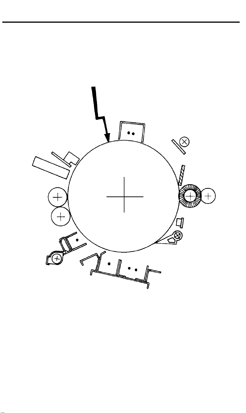
2. COPY PROCESSES AROUND THE DRUM
2
1
10
3
4
9
5
6
7
8
1-4
Page 9

Overall
Information
6 March 1992 COPY PROCESSES AROUND THE DRUM
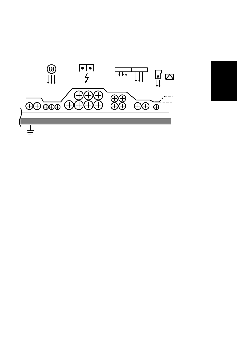
1. DRUM CHARGE
In the dark, the charge corona unit gives a uniform positive charge to the selenium drum.
The charge remains on the surface of the drum because the photoconductive selenium
has electrical resistance in the dark.
2. EXPOSURE
An image of the original is reflected to the selenium drum surface via the optics
assembly. The charge on the drum surface is dissipated in direct proportion to the
intensity of the reflected light, thus producing an electrical latent image on the drum
surface.
3. ERASE
The erase lamp illuminates the areas of the charged drum surface that will not be used
for the copy image. The resistance of the drum in the illuminated areas drops and the
charge on those areas dissipates.
4. DRUM POTENTIAL SENSOR
The drum potential sensor detects the electric lines of force from the electric potential on
the drum to compensate image processing elements.
5. DEVELOPMENT
Negatively charged toner is attracted to the positively charged areas of the drum, thus
developing the latent image. (The negative triboelectric charge is caused by friction
between the carrier and toner particles.)
6. PRE-TRANSFER
The pre-transfer corona (PTC) applies a negative dc charge and an ac charge to the
drum. The dc charge increases the negative potential of the toner to improve toner
transfer to paper. The ac charge decreases positive charge on the drum and makes
paper separation easier. The pre-transfer lamp (PTL) also makes paper separation
easier by illuminating the drum and decreasing the positive charge on the drum.
7. IMAGE TRANSFER
Paper is fed to the drum surface at the proper time so as to align the copy paper and the
developed image on the drum surface. Then, a strong positive charge is applied to the
back side of the copy paper, providing an electrical force which causes the copy paper to
be attracted to the drum’s surface. At the same time, the toner particles are pulled to the
copy paper from the drum’s surface.
8. PAPER SEPARATION
A strong ac corona discharge is applied to the back side of the copy paper, reducing the
positive charge on the copy paper and breaking the electrical attraction between the
paper and the drum. Then, the stiffness of the copy paper causes it to separate from the
drum surface. The pick-off pawls help to separate paper which has low stiffness.
9. CLEANING
The cleaning brush first removes remaining toner on the drum surface. Then, the
cleaning blade which is angled against drum rotation (counter blade system) removes
the rest of the toner. The flick roller mechanically removes the toner on the cleaning
brush.
10. QUENCHING
Light from the quenching lamp electrically neutralizes the drum surface.
1-5
Page 10
MECHANICAL COMPONENT LAYOUT 6 March 1992
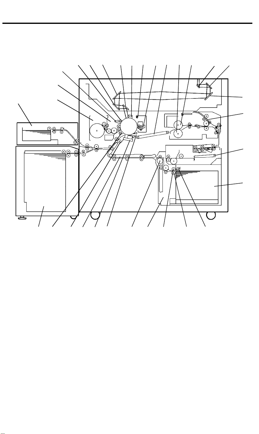
3. MECHANICAL COMPONENT LAYOUT
3.1 COPIER
18 19
22 23 24 25 26 27 28 29 30 31 1 2
21
20
3
4
5
6
7891011121314151617
1. First Mirror
2. Second Mirror
3. Third Mirror
4. Inverter Guide Plates
5. Duplex Tray
6. Third Tray
7. Pick-up Roller
8. Separation Roller
9. Paper Feed Roller
10. Vertical Transport Unit
11. Relay Rollers
12. Pick-off Pawls
13. Transfer and Separation
Corona Unit
14. Horizontal Transport Unit
15. Registration Rollers
16. Pre-transfer Corona Unit
17. Second Tray
18. First Tray
19. Toner Hopper
20. Development Unit
21. Drum Thermistor and Drum
Potential Sensor
22. Erase Lamp
23. Fifth Mirror
24. Fourth Mirror
25. Sixth Mirror
26. Charge Corona Unit
27. Quenching Lamp
28. Cleaning Unit
29. Transport Unit
30. Pressure Roller
31. Hot Roller
1-6
Page 11
Overall
Information
6 March 1992 MECHANICAL COMPONENT LAYOUT
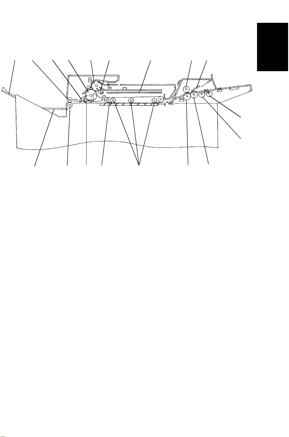
3.2 ARDF
1 2 3 4 5 6 7 8 9
10
11
12131415161718
1. Original Tray Extension
2. Upper Exit Rollers
3. Upper Inverter Gate
4. Lower Inverter Rollers
5. Upper Inverter Rollers
6. Switch Back Gate
7. Switch Back Tray
8. Upper Relay Roller
9. Friction Tab
10. 1st Pick-up Rollers
11. 2nd Pick-up Rollers
12. Separation Rollers
13. Lower Relay Roller
14. Pressure Rollers
15. Transport Belt
16. Lower Inverter Gate
17. Lower Exit Rollers
18. CFF Guide
1-7
Page 12

ELECTRICAL COMPONENT DESCRIPTIONS 6 March 1992
4. ELECTRICAL COMPONENT DESCRIPTIONS
Refer to the electrical component layout on the reverse side of the Point to
Point (Water proof paper) index numbers.
4.1 COPIER
Name Function Index. No.
Motors
1st Tray Drive Drives the bottom plate in the 1st tray. 132
2nd Tray Drive Drives the bottom plate in the 2nd tray. 139
3rd Tray Drive Drives the bottom plate in the 3rd tray. 65
Charge Wire Cleaner Drives the charge corona wire cleaner. 74
Development Drives the development unit. 51
Fusing Cooling Fan Cools fins of the de-curling roller. 58
Fusing Exhaust Fan Removes the heat in the de-curling unit. 56
Lens Horizontal Drive Shifts the lens horizontal position. 54
Lens Vertical Drive Shifts the lens vertical position. 57
Main Drives the main unit components. 73
Mirror Unit Drive Positions the mirror unit. 78
Optics Cooling Removes the heat from the optics unit. 77
Scanner Drive Drive the 1st and 2nd scanners. 55
T & S Wire Cleaner Drives the transfer and separation wire cleaner. 72
Toner Supply Rotates the toner supply roller. 75
Vaccum Fan Removes the heat and dust in the machine. 52
Clutches
LCT Drive Transmits the main copier drive to the 1st and 2nd
feed sections.
Paper Feed - 1st Tray Drives the paper feed roller of the 1st tray. 134
Paper Feed - 2nd Tray Drives the paper feed roller of the 2nd tray. 159
Paper Feed - 3rd Tray Drives the paper feed roller of the 3rd tray. 66
Paper Feed - Duplex Drives the paper feed roller of the duplex unit. 67
Vertical Transport Unit
Drive
Registration Drives the registration roller. 79
PCBs
DC Drive Drives dc components. 116
Drum Current Detection Measures the corona current. 106
Main Controls overall machine operation. 122
Motor Control Controls the dc motors. 123
DC Motor Drive Drives the dc motors. 101
Operation Unit Controls the monitor display. 124
PTL Controls the pre-transfer lamp operation. 121
Quenching Lamp Controls the quenching lamp operation. 120
Transmits the main copier drive to the vertical
transport unit and the 3rd tray.
76
68
1-8
Page 13

Overall
Information
6 March 1992 ELECTRICAL COMPONENT DESCRIPTIONS
Name Function Index. No.
Interface Interface between the main PCB and other PCBs. 115
Vaccum Motor Controls the vacuum fan motor operation. 108
Power Packs
Charge Provides power for the charge corona wire. 103
Development Bias Provides power for the development bias. 104
PTC Provides power for the pre-transfer corona wire. 107
Separation Provides power for the separation corona wire. 105
Transfer Provides power for the transfer corona wire. 102
Power Supply Unit Provides dc power to dc components. 119
Relays
Anticondensation Heater Provides power to the anticondensation heater. 113
Drum Heater 1 Provides power to the drum heater. 114
Drum Heater 2 Provides power to the drum heater. 110
Fusing SSR (16 A) Provides power to the 720 W fusing lamp. 111
Fusing SSR (20 A) Provides power to the 900/950 W fusing lamp. 112
Relay Unit Provides ac power to ac components. 118
Sensor
Auto Responce Turns on the display from the screen saver condition. 93
Drum Potential Detects the drum surface voltage. 95
Duplex Entrance Detects misfeeds. 12
Exit Detects misfeeds. 10
Fusing Unit Detects misfeeds. 9
Image Density Measures the density of the image on the drum. 87
Jogger Home Position Detects when the duplex side plate is at the home
position.
Lens Horizontal Encoder Detects the lens horizontal drive motor operation. 5
Lens Horizontal Home
Position
Lens Vertical Encoder Detects the lens vertical drive motor operation. 7
Lens Vertical Home
Position
Lower Limit - 1st Tray Turns off the 1st tray motor when the tray reaches
Lower Limit - 2nd Tray Turns off the 2nd tray motor when the tray reaches
Lower Limit - 3rd Tray Turns off the 3rd tray motor when the tray reaches
Mirror Unit Encoder Detects the mirror drive motor operation. 29
Mirror Unit Home
Position
Paper End - 1st Tray Detects the presence of paper in the 1st tray. 159
Paper End - 2nd Tray Detects the presence of paper in the 2nd tray. 146
Detects when the lens is at the horizontal home
position.
Detects when the lens is at the vertical home
position.
the down position.
the down position.
the down position.
Detects when the mirror unit is at the home position.
15
4
6
138
140
41
3
1-9
Page 14

ELECTRICAL COMPONENT DESCRIPTIONS 6 March 1992
Name Function Index. No.
Paper End - 3rd Tray Detects the presence of paper in the 3rd tray. 42
Paper End - Duplex Detects the presence of paper in the duplex tray. 13
Paper Feed - 1st Tray Turn off the 1st tray paper feed clutch. 154
Paper Feed - 2nd Tray Turn off the 2nd tray paper feed clutch. 147
Paper Feed - 3rd Tray Turns off the 3rd tray paper feed clutch. 16
Paper Feed - Duplex Turns off the duplex paper feed clutch. 18
Paper Size 1 - 1st Tray Determines what paper size is in the 1st tray. 133
Paper Size 1 - 2nd Tray Determines what paper size is in the 2nd tray. 142
Paper Size 1 - 3rd Tray Determines what paper size is in the 3rd tray. 35
Paper Size 2 - 1st Tray Determines what paper size is in the 1st tray. 157
Paper Size 2 - 2nd Tray Determines what paper size is in the 2nd tray. 143
Paper Size 2 - 3rd Tray Determines what paper size is in the 3rd tray. 34
Paper Size 3 - 1st Tray Determines what paper size is in the 1st tray. 137
Paper Size 3 - 2nd Tray Determines what paper size is in the 2nd tray. 144
Paper Size 3 - 3rd Tray Determines what paper size is in the 3rd tray. 33
Paper Size 4 - 1st Tray Determines what paper size is in the 1st tray. 135
Paper Size 4 - 3rd Tray Determines what paper size is in the 3rd tray. 32
Paper Size 5 - 3rd Tray Determines what paper size is in the 3rd tray. 39
Paper Size 6 - 3rd Tray Determines what paper size is in the 3rd tray. 38
Paper Size 7 - 3rd Tray Determines what paper size is in the 3rd tray. 37
Paper Size 8 - 3rd Tray Determines what paper size is in the 3rd tray. 36
Paper Volume - 1st Tray Detects the amount of paper in the 1st tray. 131
Paper Volume - 2nd
Tray
Detects the amount of paper in the 2nd tray.
149
Paper Volume - 3rd Tray Detects the amount of paper in the 3rd tray. 31
Pick-up Position -
Duplex
Registration Sensor Detects the lead edge of paper to determine the stop
Return Home Position Detects when the 1st scanner is at the return
Scanner Home Position Detects when the 1st scanner is at the home
Detects the duplex pick-up roller position.
timing of a feed clutch and detects misfeeds.
position.
position.
17
22
27
8
Toner Cartridge Detects when a toner cartridge is in the machine. 2
Toner Coil Overload Detects the toner collection coil drive gear operation. 1
Toner Near End Detects toner near end condition. 28
Transport Detects misfeeds. 20
Tray Paper Position Detects the top sheet position in the 2nd tray. 141
Upper Limit - 1st Tray Sends signal to stop lifting up the 1st tray bottom
plate.
Upper Limit - 2nd Tray Sends signal to stop lifting up the 2nd tray bottom
plate.
Upper Limit - 3rd Tray Sends signal to stop lifting up the 3rd tray bottom
plate.
161
158
14
1-10
Page 15

Overall
Information
6 March 1992 ELECTRICAL COMPONENT DESCRIPTIONS
Name Function Index. No.
Solenoids
2nd Tray Lock Locks the 2nd tray. 136
Cleaning Brings the cleaning blade into contact with the drum. 53
Fork Gate 1 Varies the paper path in the duplex unit depending
on paper size.
Fork Gate 2 Varies the paper path in the duplex unit depending
on paper size.
Inverter Gate Drives the inverter gate up and down. 61
Junction Gate Drives the junction gate up and down. 60
Pick-up - 1st Tray Lifts the pick-up roller of the 1st tray. 155
Pick-up - 2nd Tray Lifts the pick-up roller of the 2nd tray. 148
Pick-up - 3rd Tray Lifts the pick-up roller of the 3rd tray. 70
Pinch Roller Brings the return pinch rollers into contact with a
paper.
Pressure Plate Brings the pressure plate on papers in the duplex
unit.
Positioning Lowers the positioning roller in the duplex unit. 64
Duplex Paper Stopper Lowers the paper stopper in the duplex unit. 71
62
63
59
69
Switches
1st Tray Down Lowers the 1st tray bottom plate. 151
1st Tray Set De-energizes power when the 1st tray is slided to
the left.
2nd Tray Down Lowers the 2nd tray bottom plate. 150
3rd Tray Down Lowers the 3rd tray bottom plate. 40
Anticondensation Turns on the tray heaters. 23
Error Reset Resets error condition. 11
Left Door 1 Turns off the main motor when the left door is open. 25
Left Door 2 Turns off dc 24 volts lines when the left door is open. 24
Main Supplies power to the copier. 26
Right Door 1 Turns off dc 24 volts lines when the right door is
open.
Right Door 2 Turns off the main motor when the right door is open. 19
Tray Cover Turns off components when the tray left top cover is
open.
Heaters
1st Tray Removes humidity from the paper in the 1st tray. 156
2nd Tray Removes humidity from the paper in the 2nd tray. 145
3rd Tray Removes humidity from the paper in the 3rd tray. 92
Anticondensation Prevents moisture from forming on the lens and
mirrors.
Drum Warms the drum when it gets too cool. 96
Exposure Lamp Warms the exposure lamp when it gets too cool. 86
160
21
153
83
1-11
Page 16

ELECTRICAL COMPONENT DESCRIPTIONS 6 March 1992
Name Function Index. No.
Lamps
Exposure Exposes the original with high intensity light. 85
Fusing 1 Provides heat to the hot roller and keeps the roller at
the operating temperature.
89
Fusing 2 Provides heat to the hot roller during warm-up. 90
Pre-Transfer Removes excessive positive charge from the drum
surface to the transfer and separation process.
Quenching Electrically neutralizes the drum surface prior to
charging.
81
82
Thermistors
Drum Monitors the drum temperature. 94
Fusing Monitors the hot roller temperature. 88
Other Components
Total Counter Keeps a count of the number of copies made. 117
FL Stabilizer Stabilizes power to the exposure lamp. 109
Thermofuse Provides back-up overheat protection in the fusing
unit.
Anticondensation
Turns off the anticondensation and drum heaters.
Thermoswitch
91
84
1-12
Page 17

Overall
Information
6 March 1992 ELECTRICAL COMPONENT DESCRIPTIONS
4.2 ARDF
Symbol Name Function Index. No.
Motors
M1
M2 Belt Drives the transport belt. 16
M3 Inverter Drives the inverter rollers and the exit rollers. 17
M4 Job Separation Drives the job separator. 5
Circuit Boards
PCB1 DF Main Controls overall ARDF functions. 3
PCB2
Solenoids
SOL1
SOL2 Inverter Gate Opens the inverter gate. 23
Feed-in Drives the pick-up rollers, separation rollers
and relay rollers.
Indicator Indicates the Insert Original indicator and the
Auto Feed indicator.
Switch Back Switches the switch back gate position to
directs the original to the switch back tray or
onto the exposure glass.
2
6
15
Sensors
S1 Entrance Cover Detects if the entrance cover is open. 4
S2 Lift Detects if the transport unit is open. 14
S3 Inverter Cover Detects if the inverter cover is open. 22
S4
S5
S6
S7
S8
S9 Inverter Jam Detects paper jams in switch back operation. 18
S10
S11
S12 Exit Detects paper jams. 21
S13
S14 Original Width Detects the original width. 13
S15 Timing Supplies timing pulses to the DF main board. 10
Pick-up Roller H.P. Detects if the pick-up roller is in the home
position.
Job Separation
H.P.
Job Completion Detects that last original of the first job is fed
Original Detects if the original is set on the original
Registration Sets the feed-in motor, belt motor and inverter
Inverter
Registration
Inverter Entrance Sets the inverter motor and the belt motor off,
CFF Detects if the computer form is set in the CFF
Detects if the job separator is in the home
position.
from the original table.
table.
motor off timing. Detects original misfeed.
Sets the inverter motor and the belt motor off,
reversing timing. Detects original jams.
reversing timing, inverter solenoid and switch
back solenoid off timing.
guide. Counts the holes lined up on the
computer form.
1
7
8
9
12
19
20
11
1-13
Page 18
DRIVE LAYOUT 6 March 1992
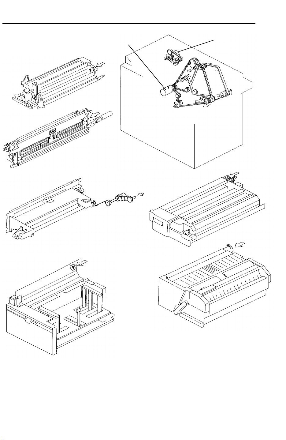
5. DRIVE LAYOUT
1
A
A
2
B
C
E
B
C
E
D
F
F
D
1. Main Motor
2. Development Drive Motor
A : Development Unit
B : Cleaning Unit
C : Relay Transport Unit (to 1st & 2nd Tray)
D : Fusing Unit
E : Vertical Transport Unit
F : Duplex Unit
1-14
Page 19

Overall
Information
6 March 1992 PAPER PATH
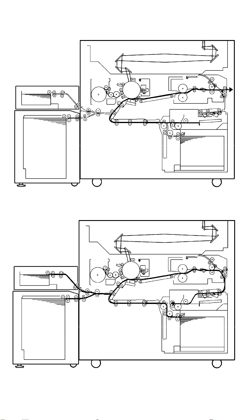
6. PAPER PATH
6.1 SINGLE SIDED COPY -- COPY FACE DOWN
6.2 DUPLEX MODE (1ST SIDE)
1-15
Page 20
PAPER PATH 6 March 1992
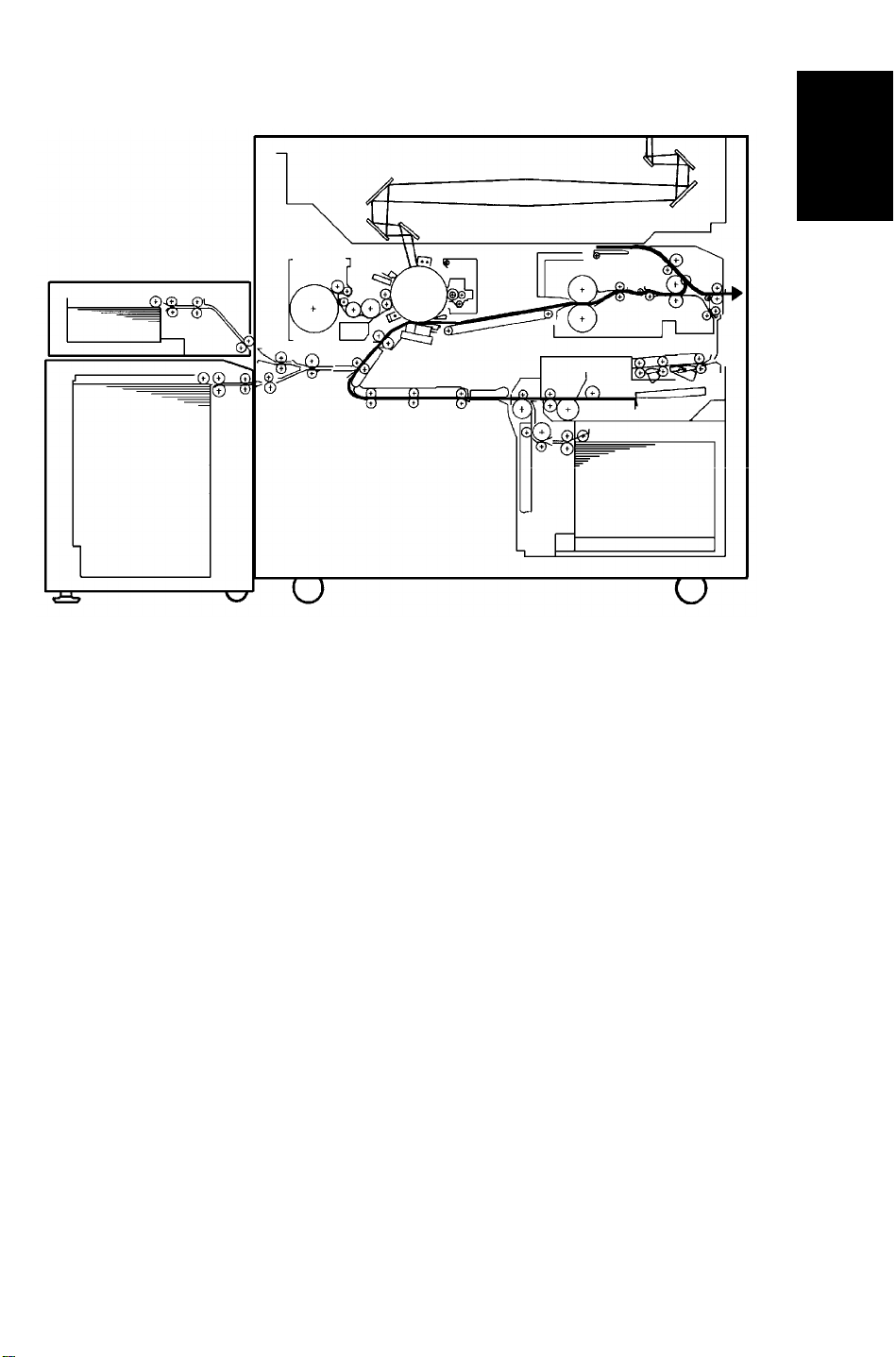
6.3 DUPLEX MODE (2ND SIDE)
6.4 IMAGE OVERLAY MODE (1ST SIDE)
1-16
Page 21
Overall
Information
6 March 1992 PAPER PATH
6.5 IMAGE OVERLAY MODE (2ND SIDE)
1-17
Page 22

SECTION 2
DETAILED SECTION
DESCRIPTIONS
Page 23
6 March 1992 PROCESS CONTROL
1. PROCESS CONTROL
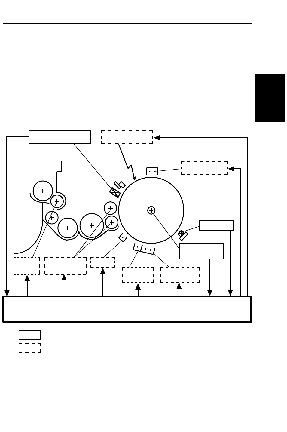
1.1 OVERVIEW
The characteristics of each unit which is related to the copy image
reproduction are changed by various factors. To get stable images over long
periods and in continuous copy runs, these characteristic changes have to be
compensated.
The following figure and table show how these factors are compensated on
this copier.
Detailed
Descriptions
Potential Sensor
Toner
Supply
Development
Bias
Exposure Lamp
PTC
Main PCB
Transfer
Corona
Charge Corona
ID Sensor
Drum Current
Detection PCB
Separation
Corona
: Sensing Item
: Controlled Item
2-1
Page 24

PROCESS CONTROL 6 March 1992
Section Characteristics Causes of Change Compensation Method
Drum Charge
Potential
Sensitivity Repeat Stress
Residual
Voltage
Charge
Corona
Exposure Lamp Intensity Repeat Stress Measure the drum potential of a part
Development Amount of
Charge
Potential
Mirror
Reflectivity
Lens Clearness
Toner Charge
Repeat Stress
Temperature
Humidity
Temperature
Humidity
Repeat Stress
Temperature
Humidity
Dirtiness
Temperature
Humidity
Dirtiness
Repeat Stress
Temperature
Humidity
Measure the drum potential of a part
that was not exposed (Dark Potential)
with the potential sensor and adjust
the charge corona output.
Measure the drum potential of a part
that was exposed (Light Potential) and
adjust the exposure lamp voltage.
Measure the drum potential of a part
that was erased by the erase lamp
(residual voltage) and adjust the
development bias, light potential, and
dark potential
Measure the drum potential of a part
that was not exposed (dark potential)
and adjust the charge corona output.
that was exposed (light potential) and
adjust the exposure lamp voltage.
Measure the reflected light intensity of
the ID sensor pattern and adjust the
toner density in the development unit.
2-2
Page 25
6 March 1992 PROCESS CONTROL
1.2 IMAGE CONTROL
1.2.1 Latent Image Control
QL
Charge
V0
Exposure
Black White
Vd
VL
Erase
Potential
Sensor
Vr
Drum
The figure shows the changes of the drum potential during the copy process.
V0: The drum potential just after charging the drum.
Vd (Dark Potential): The drum potential just after exposing the black
pattern (Vd pattern)
Detailed
Descriptions
VL (Light Potential): The drum potential just after exposing the white
pattern (VL pattern)
Vr (Residual Voltage): The drum potential just after the exposure of the
erase lamp.
2-3
Page 26

PROCESS CONTROL 6 March 1992
V0
[V]
Vd
Drum
Potential
VL
Vr
LightOriginal DensityDark
The above figure shows the relationship between the drum potential and the
original density (exposing light intensity). To get constant copy quality, this
relationship must be maintained.
Since this relationship tends to change to the one represented by the dotted
line by various factors, compensations are required as follows:
A decrease in dark voltage (Vd) is compensated for by increasing the charge
corona output. A increase in light voltage (VL) is compensated for by
increasing the exposure lamp voltage. Since the residual voltage (Vr)
increase cannot be compensated for by increasing the lamp voltage, it is
compensated by increasing the development bias voltage and changing the
Vd and VL standard value.
1.2.2 Image Density Control
To maintain constant copy image density, the ID sensor detects the toner
amount of the ID sensor pattern. From this, it is understood that drum
potential is stabilized with the above compensations. According to the
detection results, the toner density in the development unit is controlled so
that the toner amount on the sensor pattern is constant.
The following sections explain the details of these compensations.
2-4
Page 27

6 March 1992 PROCESS CONTROL
1.3 PROCESS CONTROL DATA INITIALIZATION
The following flow chart shows all the steps that will be performed whenever
the main switch is turned on while the hot roller temperature is below 100°C.
This initializes all the process control settings.
Main SW On (Fusing Temp. < 100°C)
Drum Potential Sensor Calibration
Drum Conditioning Start (Fusing Temp. = 160°C)
• Exposure lamp ON
Vsg Adjustment
Lamp Intensity Sensor Calibration
Detailed
Descriptions
Charge Corona Current Adjustment
Vr Measurement
• Lens position shift
• Exposure lamp OFF
• Scanner moves to return position (Vd Pattern)
• Exposure lamp ON
Vd Correction
• Exposure lamp OFF
• Scanner returns to home position (VL Pattern)
• Exposure lamp ON
VL Correction
• Exposure lamp OFF
V01 Detection
• Scanner moves to return position (ADS Pattern)
• Exposure lamp ON
ADS Adjustment
2-5
Page 28
PROCESS CONTROL 6 March 1992
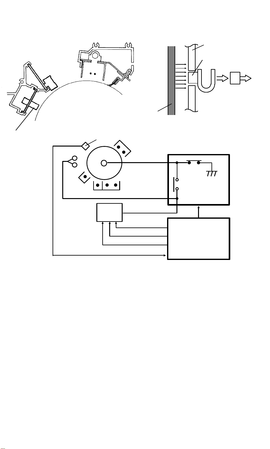
1.3.1 Drum Potential Sensor Calibration
[A]
Potential Sensor
Bias
P.P.
Case
Sensor
Output
Amp.
Drum
RA2
RA1
Drum Current
Detection PCB
Relay
TRIG 1 (800V)
TRIG 2 (100V)
PWM
Sensor
Main PCB
The drum potential sensor [A] is located just above the development unit. The
sensor has a detector which detects the electric lines of force from the
electric potential on the drum. The output of the sensor depends of the
number of electric lines of force.
Since the output of the sensor is affected by environmental conditions, such
as temperature and humidity, the sensor output is calibrated during process
control data initialization.
The drum current detection board has two relay contacts. Usually RA2
grounds the drum. However, during the initialization, the main PCB turns RA1
on and RA2 off and applies the development bias to the drum shaft.
By measuring the outputs of the drum potential sensor when +100 V and
+800V are applied to the drum, the sensor output is calibrated automatically.
2-6
Page 29
6 March 1992 PROCESS CONTROL
1.3.2 Drum Conditioning
When the drum temperature reaches 160°C, the machine starts the drum
conditioning process. In this mode, all the coronas and lamps around the
drum are activated and drum sensitivity is stabilized, as in continuous copy
runs.
1.3.3 Vsg Adjustment
During drum conditioning, the ID sensor checks the bare drum’s reflectivity
and calibrates the output of the ID sensor to +4 V.
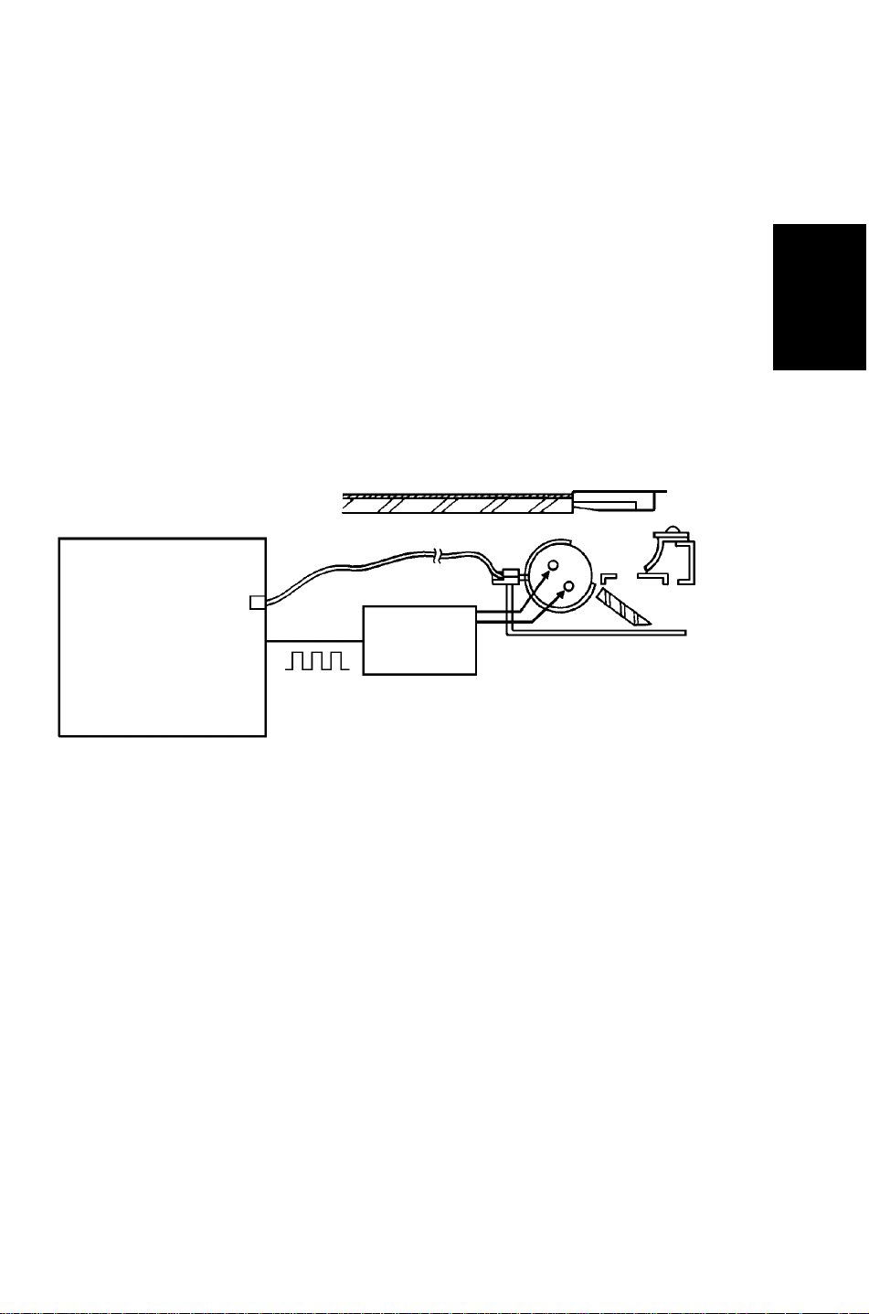
1.3.4 Lamp Intensity Sensor Calibration
Detailed
Descriptions
Main PCB
PWM
FL
Stabilizer
The exposure lamp intensity is monitored by the main PCB through the fiber
optics cable. A photodiode on the main PCB converts the light intensity to a
dc voltage. The main PCB sends a PWM signal with a 100% duty cycle to the
FL stabilizer and checks the monitored voltage, adjusting it to +3 V. This +3 V
is used as the light intensity standard.
2-7
Page 30

PROCESS CONTROL 6 March 1992
1.3.5 Charge Corona Current Adjustment
+12V
GND
-12V
CN342-3
CN342-2
CN342-1
CN341-4
RA1
CN341
-1
CN341-2
Potential S.
CN103-B24
Id Set
CN103-A14
CN104-A28
CN104-B1
CN104-A1
RA2
RA2
RA1
HIC1
CN342
-4
T343
CN342
CN342
-5
-6
-7
-8
Drum Current Detect PCB MainPCB
PCL
DC
AC
The charge corona current is measured and adjusted automatically by the
drum current detect PCB.
The charge corona current flows to the drum current detect PCB through the
drum and the drum shaft. The drum shaft is grounded by the drum current
detect PCB usually. However, during the process control data initialization,
the main PCB activates the corona current circuit in the drum current
detection PCB which converts the drum current to a voltage and separates it
into ac and dc component outputs. Then, the main PCB reads them through
A/D converters as digital data. The main PCB adjusts the corona current by
controlling the PWM signal to the charge corona power pack.
When the auto drum current adjustment mode is selected by the SP mode,
the drum current detect PCB is used to measure and adjust other corona
outputs in the same way.
2-8
Page 31

6 March 1992 PROCESS CONTROL
1.3.6 Vr Measurement
[V]
Drum
Potential
V0
Vd
VL
Vr
Dark Light
Original Density
The drum residual voltage (Vr) tends to increase during the drums life due to
electrical fatigue. The residual voltage cannot be reduced even if the
exposure lamp voltage is increased. Therefore, the Vr change has to be
compensated by other means.
Detailed
Descriptions
The main PCB checks the drum potential just after the erase lamp exposure,
by the drum potential sensor during drum conditioning. The drum potential is
in fact Vr. This measured Vr is used as the standard for the following other
compensations.
1. Vd Correction
2. VL Correction
2-9
Page 32

PROCESS CONTROL 6 March 1992
1.3.7 Vd Correction
[V]
Vd
Drum
Potential
Exposure
Glass
Vd Pattern
Dark
Original Density
Vr
Light
The drum potential just after the black pattern (Vd Pattern) is exposed (Vd:
Dark Potential) tends to lower during drum life due to a decrease in the
drum’s capacity to carry a charge.
To check the actual Vd, the first scanner moves to the return position and the
Vd pattern (Black) stuck on the bottom side of the exposure glass bracket is
exposed on the drum.
The main PCB measures Vd through the drum potential sensor and adjust it
to a target value by adjusting the charge power pack output.
On the other hand, there is a change of the drum residual voltage (Vr), so
that the target Vd voltage is compensated as follows:
Target Vd Value: Vd = Vr + 770 V
The adjusted charge power pack output control value (PWM value) is kept in
memory until the next initialization.
If the target value cannot be achieved within the charge power pack output
control range, the copier indicates the system error on the CRT screen. The
copier tries the Vd check again after the error reset. Even if the second Vd
adjustment fails, no SC condition is displayed. The previous power pack
output control data will be used in this case.
2-10
Page 33

6 March 1992 PROCESS CONTROL
1.3.8 VL Correction
[V]
VL Pattern
Drum
Potential
Dark
VL
Original Density
Vr
Light
Detailed
Descriptions
Dirty optics and/or exposure lamp deterioration decreases the intensity of the
light that reaches the drum. In addition to this, the drum sensitivity also
changes during the drum’s life. These factors change the drum potential just
after white pattern exposure (VL: Light Potential).
To check the actual VL, the first scanner moves to the home position and the
VL pattern (White) stuck on the bottom side of the exposure glass bracket is
exposed on the drum.
The main PCB measures the VL through the drum potential sensor and
adjusts it to a target value by adjusting the exposure lamp output.
The residual voltage change also affects VL, so that VL’s target voltage is
compensated as follows:
Target Value of VL: VL1 = Vr + 50 -- 5N (volt)
NOTE: N is the setting for the exposure lamp adjustment in the SP mode.
Maximum of 5N = 50
The adjusted exposure lamp output control value (PWM value) is kept in
memory until the next initialization.
If the target value cannot be achieved within the exposure lamp output
control range, the copier indicates the system error on the CRT screen. The
copier tries the VL check again after the SC reset. Even if the second VL
adjustment fails, no SC condition is displayed. The previous exposure lamp
output control data will be used in this case.
2-11
Page 34

PROCESS CONTROL 6 March 1992
1.3.9 V01 Measuring
[V]
Drum
Potential
Dark
V0
Vd
Original Density
Light
Since the ID sensor pattern on the drum is made by the erase lamp and
charge corona (except for B4/81/2" x 14" copy mode due to the lens horizontal
movement. See toner density detection and supply section for details), the
sensor pattern density varies with drum potential just after the charge corona
(V0) is applied.
To measure the toner density properly, the development bias for the ID
sensor pattern is corrected by measuring the actual drum potential after the
charge corona.
During the process control data initialization, the drum potential after the
charge corona is applied when the drum sensitivity is stabilized (V01) will be
measured and used to determine the bias voltage for the ID sensor pattern
development in continuous copy run. The details will be explained in the
toner density detection section.
2-12
Page 35

6 March 1992 PROCESS CONTROL
1.3.10 ADS Adjustment
Exposure Glass
ADS Pattern
ADS Pattern
Detailed
Descriptions
The ADS pattern is located underneath the exposure glass bracket. During
the process control data initialization, the ADS reference voltage is adjusted.
When the first scanner is moved to the return position for the Vd adjustment,
the main PCB checks the ADS voltage through the ADS fiber optics cable.
The measured voltage is calibrated to the standard voltage (3 V) as the
reference for the auto image density control.
2-13
Page 36

PROCESS CONTROL 6 March 1992
1.4 COMPENSATIONS DURING COPY CYCLE
During continuous copying, the drum sensitivity changes due to the electrical
fatigue. The drum sensitivity also changes during rest time.
The following compensations are used for the drum sensitivity changes in the
copy cycle:
VL Pattern
[V]
Drum
Potential
V0
Vd
VBB
VL
Vr
Dark Light
Original Density
1.4.1 VL Compensation
The drum light potential (VL) is changed during the copy cycle.
To get constant image quality in continuous copy runs, the development base
bias is compensated during the copy cycle.
At the beginning of each original scanning, the VL sensor pattern is
developed on the drum. The main PCB monitors the drum potential (VL2) of
the latent image of the VL sensor pattern through the drum potential sensor,
and adjusts the development base bias.
See development bias section for details.
Development Base Bias: VBB = VL2 + 170 + 5N
NOTE: N is the setting for the exposure lamp adjustment in the SP mode.
2-14
Page 37

6 March 1992 PROCESS CONTROL
1.4.2 V02 Measuring
Start key
Charge
Corona
Exposure
Lamp
Scanner
Drum
Potential
Sensor
F
R
V02 VL2 VL2 VL2 VL2 VL2 VL2 VL2 VL2
9 10 112 3 4 51
Detailed
Descriptions
During the process control data initialization, V01 is measured to determine
the development bias for the ID sensor pattern in continuous copy runs. This
bias cannot be used for the initial part of the copy run (less that 10 copies)
due to the different drum potential after the charge corona is applied.
Whenever the Start key is pressed, the drum potential after the charge
corona is measured at the beginning of the copy run (V02).
V02 is used to determine the development bias voltage for the ID sensor
pattern which is made at the first copy.
The details will be explained in the Image Density Control section.
2-15
Page 38

DRUM 6 March 1992
2. DRUM
2.1 OVERVIEW
[E]
[A]
This model uses an FO-type drum made by applying an urethane resin
coating [A] on an F-type drum [B]. This coating provides a long life and
minimize the white line problems on the half-tone areas.
[C]
Al
[B]
[F]
[D]
For the F-type drum, the charge carrying layer [C] is made by the drum
conditioning. Since the FO-type drums are coated after the charge carrying
layer has been made, it is not necessary to perform the drum conditioning at
the new drum installation.
When drum temperature drops below the permissible level, extreme
sensitivity changes occur. Additionally, the temperature changes can cause
condensation. To maintain a constant drum temperature, a drum heater [D]
(100 V 140 W) which is controlled by a thermistor [E] and two thermoswitches
[F] is used.
2-16
Page 39

6 March 1992 DRUM
2.2 DRUM HEATER CONTROL
160°C 65°C
CN-3
CN-2
CN-1
RA354
RA353
AC100V
Drum Heater
RA
Drum Thermistor
RA353RA354
RA
Drum Heater 1
Drum Heater 2
24V
CN251-B25
24V
CN251-B30
5V
CN251-B26
CN251-A30
Relay PCB
Drum Thermistor
CN255-B9
CN255-A28
CN104-A4
Drum
Heater 1
Drum
Heater 2
A/D
Converter
CN102-A2
CN103-B26
Main PCB
24V
ON
The drum thermistor monitors the drum surface temperature. When the
measured temperature reaches 41°C, the main PCB determines that the
copier is ready to make copies.
When the main switch is off, the drum heater relays (RA353 and RA354) are
off, so that the drum heater is controlled by the 65°C thermoswitch. The
thermoswitch is on at 50°C and off at 65°C.
Detailed
Descriptions
When the main switch is on, RA354 is on and bypasses the 65°C
thermoswitch from the drum heater control circuit. RA353 turns on or off
according to the temperature detected by the drum thermistor.
The drum surface temperature is controlled between 41°C and 50°C.
To minimize the power consumption, RA353 is turned on to bypass the drum
heater during the copy cycle.
2-17
Page 40

DRUM CHARGE 6 March 1992
3. DRUM CHARGE
3.1 CHARGE CORONA UNIT
[A]
This copier uses a dual carbon coated tungsten wire corotron for the drum
charge. The corona wire generates a corona of positive ions when the charge
power pack [A] applies a high voltage.
The output of the charge power pack is determined by the CPU based on the
process control data.
The charge power pack has a leakage sensor. If a leak (short circuit) is
sensed, the output is interrupted.
2-18
Page 41

6 March 1992 DRUM CHARGE
3.2 CORONA UNIT VENTILATION
Detailed
Descriptions
If ozone produced by the corona charge stays in the charge corona area, it
may cause uneven corona charging to the drum. To prevent this, ozone is
vacuumed out by the vacuum fan through the duct and toner filter in the
transport unit, then changed to oxygen by the ozone filter before blown out of
the copier.
2-19
Page 42

DRUM CHARGE 6 March 1992
3.3 CORONA WIRE CLEANER
Paper dust, or toner particles on the charge corona wires may interfere with
charging and cause an uneven charge on the drum. The wire cleaner
prevents this problem by automatically wiping the charge corona wires clean.
Once every 5000 copies, the wire cleaner is activated when the main switch
is turned on. The hot roller temperature must be less than 100°C for the wire
cleaner to be activated.
When the dc motor in the front end block turns on, it drives the cleaner
bracket from the home position to the rear end of the corona unit and then
back again.
2-20
Page 43

6 March 1992 DRUM CHARGE
3.4 CHARGE CORONA POWER PACK
CN311-8
CN311-1
CN311-10
24VP
24V
GND24VP
DC Power Supply
CN302-3 CN302-4
CN304-1
A
RA
CN303-2
303
CN341-6
CN341-8
Door
SW
A
24 V
GND
Drum Current
CN103-A22
DC Drive PCB
Detect PCB
PWM
TRIG
Main PCB
Charge
Corona P.P.
The main PCB sends a PWM (Pulse Width Modulation) signal to the charge
corona power pack. According to the PWM ratio, the dc power pack outputs a
high dc voltage to the charge corona wires. The main PCB determines the
PWM ratio based on the process control data.
Detailed
Descriptions
There is a safety relay (RA303) on the dc drive board which is activated by a
signal from the main PCB. In case of the SC conditions related to the high
voltage devices and the abnormal exposure lamp on, the main PCB turns the
RA303 to cut the power of dc 24 V to the power pack through its contact.
2-21
Page 44

ERASE 6 March 1992
4. ERASE
4.1 OVERVIEW
[A]
The electrical charge of the area that does not require any image will be
removed by the erase lamp unit [A].
This reduces toner consumption, and the load of the cleaning unit.
The erase lamp unit consists of 90 yellow-green LEDs. This reduces drum
light fatigue and allows precise control of the light width.
The erase lamp unit is controlled by the main PCB based on factors such as
the reproduction ratio, paper size, SP mode settings, and the image editing
settings.
The maximum erase margin error in the image editing mode is 6 mm.
2-22
Page 45

6 March 1992 ERASE
4.2 ERASE LAMP CIRCUIT
5V
OFF ON
CLOCK
LATCH
CN113-6
CN113-2
CN113-7
CN113-3
CN113-1
CN113-4
CN113-5
S-IN
GND IS
GND CK
LATCH
5V
5V
CK
CN651-5
CN651-E
CN651-6
CN651-F
CN651-4
CN651-2
CN651-8
S-IN
CLK
DCKQ
FF
LATCH
D
FF
CK
Q
CN651-C
CN561-1
CN561-A
CN561-3
GND
5V LED
GND-LED
CN311-8
CN311-15
CN311-16
Main PCB Erase Lamp Unit DC Power
Supply
The main PCB sends the serial bit data to the erase lamp unit with the clock
signal. The latch signal holds the ON/OFF condition of the LEDs.
The following charts show the erase lamp control timing.
1. When the ID sensor pattern is not made.
(A4/LT, Full Size, and 3rd Feed Mode)
Start Main Motor ON Regist Trail Edge Main Motor OFF
Detailed
Descriptions
1102*1 420* 1633
300 204
VL Pattern
All ON
816 *1
82
All ON
47*3
53*3
50
2. When the ID sensor pattern is made.
(A4/LT, Full Size, and 3rd Feed Mode)
Start Main Motor ON Regist Trail Edge Main Motor OFF
300 204
All ON
816*1
1466 *1
1602 *1
108
5954
82
420*2 1633
All ON
47*3
53*3
VL Pattern
50
ID PatternV02
NOTE: 1. Depends on the paper feed station.
2. Depends on the paper size.
3. Will be changed in Margin Adjustment and Image Editing Mode.
2-23
Page 46

OPTICS 6 March 1992
5. OPTICS
5.1 OVERVIEW
[A]
[C]
[B]
The optics unit reflects an image of the original on the exposure glass onto
the selenium drum. This forms a latent electrical image of the original.
On this model, to minimize power consumption, a fluorescent lamp is used
for the exposure lamp [A].
Six high reflection mirrors are used to make the optics unit smaller and obtain
a the wide reproduction ratio range (50 -- 200%).
The lens [B] is driven by two stepper motors for (1) vertical direction (parallel
to the paper feed direction) and (2) horizontal direction movements.
To correct focal length change in reduction and enlargement modes, the
mirror unit [C] (4th and 5th mirrors) position is adjusted by a stepper motor.
The exposure glass has a special coating on one side to minimize the static
electricity which may be produced by the original using the document feeder.
The coated side is marked and should face up.
2-24
Page 47

6 March 1992 OPTICS
5.2 SCANNER DRIVE
[C]
[D]
[A]
Detailed
Descriptions
[B]
A dc servo motor is used as the scanner drive motor [A].
The scanner drive motor drives first [B] and second scanner [C] using four
scanner drive wires. The second scanner speed is half of the first scanner
speed.
The first and second scanners are supported by the front and rear guide rails
[D]. To minimize the friction between the scanners and guide rails, the play of
the scanner movement is minimized by high wire tension.
2-25
Page 48

OPTICS 6 March 1992
5.3 SCANNER POSITION SENSORS
[A]
[B]
There are two scanner position sensors located at the front side of the optics
unit.
The scanner home position sensor [A] is used to detect the home position at
the machine initialization and during the scan cycle.
The scanner return position sensor [B] is used to detect the scanner position
for the process control data initialization (Vd and ADS data). The return
position sensor is not used during normal copying.
2-26
Page 49

6 March 1992 OPTICS
5.4 VERTICAL LENS DRIVE
[B]
[A]
The lens vertical drive motor [A] changes the lens vertical position in
accordance with the selected reproduction ratio.
A stepper motor (Approx. 1.8° (0.05 mm)/step) is used to drive the lens
through the lens drive belt.
The lens vertical home position sensor [B] detects the lens vertical position
for full size mode. The motor control PCB keeps track of the lens position
based on the number of pulses sent to the lens vertical drive motor.
[C]
Detailed
Descriptions
The lens vertical drive encoder [C] installed on the drive pulley is used to
detect if the vertical lens base locks.
2-27
Page 50

OPTICS 6 March 1992
5.5 HORIZONTAL LENS DRIVE
[B]
[A]
The original horizontal position on the exposure glass varies in modes (such
as platen, ADF, and CFF modes) for easy original handling. On the other
hand, the center is the standard position of the paper feed.
Therefore, the lens horizontal position has to be changed according to paper
size, reproduction ratio, and the original modes.
A stepper motor (approx. 7.5° (0.35 mm)/step) is used to drive the lens
through the lens drive wire.
The lens horizontal home position sensor [A] is used to detect the lens
horizontal position for A4/LT sideways, full size, and ADF mode.
The other positions are determined by counting the number of motor drive
pulses.
The lens horizontal drive encoder [B] installed on the drive pulley is used to
detect if the horizontal lens base locks.
2-28
Page 51

6 March 1992 OPTICS
5.6 HORIZONTAL LENS POSITIONING
5.6.1 For Original Position
Copy Paper
6.35
2.5
100%
Lens Position
Horizontal
CFF
12.7
ADF
5
Platen
Original Front
Edge
There are three standard original positions for the platen, ADF, and CFF
modes.
ADF mode original position is 5 mm to rear of the platen mode original
position to maintain the original transport path (5 mm from the front scale).
CFF mode original position is 17.7 mm (5 + 12.7 mm) to rear of the platen
mode original position. This is to maintain the traction hole part transport path
(12.7 mm) in ADF.
The above figure shows the lens horizontal positions for each original mode
when the identical size paper is used.
Detailed
Descriptions
5.6.2 For Paper Size
Copy Paper
100%
Lens
Position
Horizontal
Original Front
Edge
To keep the high paper feed performance, the center is assigned as the
paper feed standard position. Therefore, the lens horizontal position is
changed according to the paper size.
The figure shows the lens horizontal position for each paper size in full size
mode.
2-29
Page 52

OPTICS 6 March 1992
5.6.3 For Reproduction Ratio
50%
Copy Paper
Vertical
100% 200%
Horizontal
Lens Position
Original
Front Edge
When the reproduction ratio is changed, the vertical position of the lens is
changed. At the same time, the total focal length has to be changed to adjust
the image focusing. For this focal length change, the horizontal position of the
lens is also adjusted.
The figure shows the lens horizontal position for 50, 100 and 200%.
2-30
Page 53

6 March 1992 OPTICS
5.7 MIRROR UNIT DRIVE
[A]
Detailed
Descriptions
To compensate the focus change at the reproduction change, the mirror unit
(4th and 5th mirrors) position is changed.
A stepper motor (Approx. 7.5° (0.1 mm)/step) is used for the mirror unit drive.
A mirror unit home position sensor [A] is used to detect the unit position for
full size mode. The motor control PCB keeps track of the unit position based
on the number of motor drive pulses.
2-31
Page 54

OPTICS 6 March 1992
5.8 MOTOR DRIVE CIRCUIT
Sensors Encoders
Main
PCB
Serial
Interface
Motor
Control PCB
E
Encoder
DC Motor
Drive PCB
Scanner
M
Drive
Horizontal
M
Drive
Vertical Drive
M
Mirror Unit
M
Drive
The motor control PCB communicates with the main PCB through the serial
interface lines. The motor control PCB monitors all the sensor signals and
controls the motors through the dc motor drive PCB.
The development motor and the main motor are also be controlled by the dc
motor control PCB.
2-32
Page 55

6 March 1992 OPTICS
5.9 EXPOSURE LAMP UNIT
[C]
[A]
Detailed
Descriptions
[B]
[D]
This copier uses a fluorescent lamp [A] (100 V 84 W). This has the following
advantages:
• Low power consumption
• There is no bright point and it is easy to get even luminescence
• A narrow light wave band allows more accurate focusing for various
kinds of originals
• High-speed scanner operation vibration resistance
• Omni-directional luminescence reduces original shadow
Since low fluorescent tube temperature will result in delayed lighting and
intensity variation, a tube-type heater (38 V 60 W) [B] is used to maintain the
fluorescent tube temperature at approximately 40°C.
The lamp unit has a thermofuse [C] to monitor the lamp temperature and a
thermofuse [D] (139°C) for safety.
2-33
Page 56

OPTICS 6 March 1992
5.10 EXPOSURE LAMP CONTROL
[C]
PWM
[B]
[A]
Exposure lamp intensity must be stabilized during the copy cycle to get a
constant latent image on the drum. The main PCB [A] monitors and maintains
the light intensity through a fiber optics cable [B]. According to the measured
value, a lamp power signal (PWM signal) is sent to the fluorescent lamp
stabilizer [C].
The PWM signal output is determined based on the standard value (+3 V at
PWM 100% duty cycle) which is set at the process control data initialization
(see the Process Control Section for details).
2-34
Page 57

6 March 1992 OPTICS
5.11 AUTO IMAGE DENSITY CONTROL
50 mm 26 mm
26 mm
50 mm
166 mm
Detailed
Descriptions
The original background density is read through a fiber optics cable on the
exposure lamp unit. The sampled strip is at the leading edge of the original
and the size depends on the scanner speed (reproduction ratio).
The fiber optics cable conducts the light to a photodiode on the main PCB.
The photodiode then converts the density to the ADS voltage. The CPU
compares it with the standard ADS value (+3 V), which is set at the process
control data initialization by checking density of the white pattern underneath
the left exposure glass holder and adjust the development bias accordingly.
Detailed bias control is described in the development bias section.
2-35
Page 58

OPTICS 6 March 1992
5.12 UNEVEN LIGHT INTENSITY CORRECTION
[B]
[A]
[C]
The slit plate [A] corrects the uneven light intensity at the ends and center of
the fluorescent lamp [B] and evenly distributes light reflected from the original.
To compensate for reduced light at the lens edges, the shading plate [C] is
located in front of the lens. Additionally, the shading plate compensates the
light intensity when the lens horizontal position is shifted.
2-36
Page 59

6 March 1992 OPTICS
5.13 ANTI-CONDENSATION HEATER
[B]
[A]
To prevent condensation in the optics unit, a 40 W anti-condensation heater
[A] is installed at the bottom of the lens unit.
The anti-condensation heater is controlled by a thermoswitch [B] (On at
17°C, Off at 25°C) under the following conditions:
Detailed
Descriptions
1. The main switch is off.
2. The main switch is on, fusing lamp off in stand-by mode.
3. Machine off condition in weekly timer mode.
The anti-condensation heater has a thermofuse (169°C).
5.14 OPTICS COOLING FAN
[B]
[A]
[C]
The light intensity will be decreased if the fluorescent lamp temperature
becomes too high. The optics cooling fan [A] blows in cool air from outside
through an air filter [B]. Air from the fan also passes through the 6th mirror slit
[C] to the drum area. This prevents the optics area from being contaminated
by scattered toner in the drum unit.
2-37
Page 60

DEVELOPMENT 6 March 1992
6. DEVELOPMENT
6.1 OVERVIEW
[E]
[G]
[D]
[C]
[F]
[A]
[B]
This copier uses a double roller (diameter 20 mm each) development system.
This system differs from single roller development system in that (1) it
develops the image in a narrow area and (2) it develops the image twice.
Also, fine toner and developer (smaller particle size) are used. As a result,
the image quality, especially of thin lines, the trailing edge of half-tone areas,
and black solid areas are improved.
A dc motor is used to drive the development unit.
The developer is supplied to the developer guide [A] upper side by the
paddle roller [B]. The magnet of the upper development roller [C] attracts the
developer to the roller surface.
The doctor blade [D] trims the developer to the desired thickness and creates
back spill to the cross mixing mechanism [E]. The developer is transferred to
the lower development roller [F] and then returned to the agitator roller [G]
area via a paddle roller.
The development motor has two speeds. When the motor turns at high
speed, the developer is supplied to the development rollers. After image
development, the motor turns at slower speed to return the developer to the
development unit from the development roller sleeves. This prevents
developer spillage during the unit replacement.
The development rollers are given a positive bias to prevent the toner from
being attracted to the non-image areas, on the drum surface, that may have a
slight residual positive charge. The bias voltage is determined based on the
factors checked by the process control system.
2-38
Page 61

6 March 1992 DEVELOPMENT
6.2 DRIVE MECHANISM
[G]
[E]
[F]
[A]
[D]
[C]
[B]
All the development unit parts, except the toner supply brush, are driven by
the development drive motor (dc motor).
Detailed
Descriptions
The toner supply brush is driven by the toner supply motor.
The development motor drives the development drive gear through two
timing belts. The rotation is transferred as follows:
Upper/Lower
Development
Drive Gear [A]
Auger
Drive
Gear [B]
Idle Gear [C]
Timing Belt [E]
Dev. Roller [D]
Toner Mixing Vane
Drive Gear [F]
Idle Gear
Paddle Roller [G]
Since reversed toner mixing vane rotation could damage something, a
one-way clutch is installed to the mixing vane drive gear.
2-39
Page 62

DEVELOPMENT 6 March 1992
6.3 CROSS MIXING
[E]
[A]
[D]
[C]
[B]
This copier uses a standard cross-mixing mechanism to keep the toner and
developer evenly mixed. It also helps agitate the developer to prevent
developer clumps from forming, and helps create the triboelectric charge.
The developer on the turning upper development roller is split into two parts
by the doctor blade. The part trimmed by the doctor blade goes to the
backspill plate [A].
As the developer slides down the backspill plate to the agitator [B], the mixing
vanes [C] move it slightly toward the rear of the unit.
Part of the developer falls into the auger inlet [D] and is transported to the
front of the unit by the auger [E].
The agitator moves the developer slightly to the front as it turns, so the
developer stays level in the development unit.
2-40
Page 63

6 March 1992 DEVELOPMENT
6.4 DEVELOPMENT BIAS
6.4.1 Bias Power Pack
Potential Sensor
Bias
P.P.
PWM Duty Cycle = t2/t1 x 100 (%)
Output = 10 x PWM Duty Cycle (V)
TRIG 1 (800V)
TRIG 2 (100V)
PWM
Sensor
t2
t1
RA2
RA1
Drum Current
Detection PCB
Relay
Main PCB
Detailed
Descriptions
TRIG1 TRIG2 OUTPUT (V)
L H +800
H L +100
L L depends on the PWM signal
H H 0
The bias power pack has three input terminals. Two of them are used as the
output selector as shown in the table. When both terminals are low, the
output can be controlled by the other input terminal which receives the PWM
signal from the main PCB.
+800 and +100 V are used to calibrate the drum potential sensor in the
process control data initialization.
2-41
Page 64

DEVELOPMENT 6 March 1992
6.4.2 Bias Control In Copy Cycle
The bias output is determined by four factors.
The total bias is described as;
VB = VBB + VBA + VBS (ADS Mode)
VB = VBB + VBM (Manual ID Mode)
1) Base Bias (VBB)
[V]
Drum
Potential
Dark
V0
Vd
Original Density
VL
VBB
Vr
Light
As explained in the process control section, the base bias for development is
determined by the drum light potential (VL) measured in each original scan.
The base bias is also affected by the exposure lamp adjustment setting in the
SP mode.
VBB = VL2 + 170 + 5N
NOTE: N = Number of the lamp adjustment setting in SP mode.
2) ADS Compensation (VBA)
(V)
260
200
100
0
Dark ADS voltage (V) Light
1 2 3
0.97 V
2.75 V
According to the original background density, the bias is compensated. The
compensation value is determined with the voltage measured by the ADS
sensor (ADS Voltage) as follows:
VBA = --146 x (VADS -- 2.75)
NOTE: VBA has a limited range from 0 V to +260 V.
2-42
Page 65

6 March 1992 DEVELOPMENT
3) Manual ID Selection Position Compensation (VBM)
(V)
120
60
0
7 4
--60
--120
--180
1
ID Selection
According to the manual ID selection position, the bias is compensated as
follows:
VBM = 60 x M -- 240 (When M = 1 to 6)
60 x M -- 360 (When M = 7)
NOTE: M = Manual ID selection position. M ranges from 1 (darkest) to 7
(lightest).
When manual ID is set to 7 (lightest), the charge corona output is
lowered by 10% PWM duty cycle.
Detailed
Descriptions
4) SP Mode ID Selection Compensation (VBS)
In the SP mode, the image density level in the ADS mode can be selected
from four steps. The VBS is determined by the SP setting as follows:
Selected level VBS (V)
L +60
N 0 (Default)
H --60
VH --120
2-43
Page 66

DEVELOPMENT 6 March 1992
6.4.3 Bias for the ID Sensor Pattern
A3/11" x 17"
Lens Position
VL Pattern
B4/81/2" x 14"
A4/81/2" x 11"
Exposure Glass
ID Sensor
Pattern
Outside
The lens horizontal position is different in the used paper size on this mode.
On the other hand, the ID sensor position is fixed at one position. Therefore,
the ID sensor pattern on the back side of the exposure glass bracket will be
positioned on the drum only when B4/81/2" x 14" size paper is used.
The sensor pattern on the drum is made for each paper size as follows
(100%):
Paper Size Pattern (Black)
A4/A5/81/2" x 11"/51/2" x 81/2" Outside image of exposure glass (no light)
B4/81/2" x 14" ID sensor pattern on the exposure glass
bracket
A3/11" x 17" Exposure lamp off (no light)
The potential of the drum in these cases, the no light and the ID sensor
pattern exposure, is not the same. So the ID sensor bias (VBP) is determined
using two base voltages, V0 for the no-light condition and VD for the pattern.
VBP (no light) = --360 + V0
VBP (ID Pattern) = --360 + Vd
The Vd value which is determined during the process control data
initialization will be used.
V01 and V02, which are explained in the process control section, are used for
the VBP calculation as the V0 (drum potential after the charge corona) value.
The VBP can be changed by the SP mode (Toner Density Correction).
The following compensation will be applied to the above VBP.
Setting L N H VH
(V) --60 0 +60 +120
Default: H (+60 V)
2-44
Page 67

6 March 1992 TONER DENSITY DETECTION AND SUPPLY
7. TONER DENSITY DETECTION AND SUPPLY
7.1 TONER SUPPLY MECHANISM
[B]
[A]
[B]
[D]
[C]
The main PCB monitors the ID sensor pattern density on the drum through
the ID sensor once every ten copies and turns on the toner supply motor
when the pattern density is low (if Vsp/Vsg ≥ 1/13).
The toner supply motor [A] turns the toner supply roller [B] for a certain period
based on the paper size and the supply amount set by SP mode.
Detailed
Descriptions
A brush roller with low rotation torque and that can supply large amounts of
toner even with low operation speed, is used for the toner supply roller.
Toner mixing vanes [C] turn slowly while contacting the inner wall surface of
the toner tank whenever the development motor is turning. This prevents
toner blockages, and supplies toner to the toner agitator [D].
2-45
Page 68

TONER DENSITY DETECTION AND SUPPLY 6 March 1992
7.2 TONER DENSITY DETECTION
7.2.1 ID Sensor Pattern Production
Main SW
ON
Counter A
Counter B
ID Sensor Pattern
Start Key
Start Key Start Key
1 2 3 1 2 10
1 2 3 1 2 10 11 1 2
1 2 3 4 5 13 1 2 3
11
1 2
Drum sensitivity varies from copy to copy. Especially, drum rest time affects
drum sensitivity.
To compensate the sensitivity changes in the copy run, the ID sensor
development timing and development bias is controlled using two copy
counters.
Counter A:
Counts the copy number. Resets when the Start key is pressed.
Counter B:
Counts the copy number. Resets if the accumulated number is 10 or
above when the Start key is pressed, or when the ID sensor pattern is
made.
NOTE: Both counters are reset when the main switch is turned on or the
doors are opened.
The ID sensor pattern is made in the following conditions:
1) At the leading edge of the first copy cycle after the main switch is
turned on or when the doors are opened.
2) If A ≥ 10
At the trailing edge of the copy cycle when;
A = 10n (n: any numeric number)
3) If A < 10
When the last copy is finished and B ≥ 10, then the pattern is
developed at the leading edge of the next copy cycle.
2-46
Page 69

6 March 1992 TONER DENSITY DETECTION AND SUPPLY
7.2.2 Toner Density Detection
(V)
Vsg = 4.0
1/13 Vsg = 0.31
LED
ON
LED
ON
Detailed
Descriptions
Vsg
0
Bare
drum
Sensor
pattern
(T)
Vsp
Vsg
Vsp
Low image
density
1/13 Vsg
0
High image density
The ID sensor measures the density of the ID sensor pattern developed on
the drum. The main PCB receives two values of the sensor output, the value
for the sensor pattern (Vsp) and the value for the bare drum (Vsg).
Toner will be supplied under the following condition:
Vsp/Vsg ≥ 1/13
2-47
Page 70

TONER DENSITY DETECTION AND SUPPLY 6 March 1992
7.2.3 ID Sensor Abnormal Conditions
a. Vsp Abnormal
If the measured Vsp is 1.4 V (when Vsg = 4 V) or more and this condition is
detected five times in a row, a system error condition will be indicated on the
CRT and the 7% fixed toner supply control will be used for the rest of the
copy run.
b. Vsg Abnormal
If the measured Vsg during ID sensor pattern detection is 2.5 V or less and
this condition is detected five times in a row, a system error condition will be
indicated on the CRT and the 7% fixed toner supply control will be used for
the rest of the copy run.
If both abnormal values return to normal during the copy run, the toner supply
control will also be returned to normal.
7.3 TONER SUPPLY AMOUNT
Vsp (V)
(at Vsg = 4.0 V)
0.3 ≤ Vsp < 0.4
0.4 ≤ Vsp < 0.5
0.5 ≤ Vsp
The toner supply ratio is determined based on the supply amount data in SP
mode and Vsp values as shown in the above table.
The table shows the amount for the A3/DLT mode. When smaller paper is
used, the supply amount becomes half.
The toner supply roller turns for a period based on the selected supply ratio.
Toner Supply Amount Data in SP Mode
15% 30% 45% 60%
7 15 15 30
15 30 45 45
30 45 60 60
2-48
Page 71

6 March 1992 TONER DENSITY DETECTION AND SUPPLY
7.4 TONER CARTRIDGE
[A]
Detailed
Descriptions
[B]
When the toner cartridge is set, the toner cartridge sensor [A] is de-actuated.
The main PCB monitors the toner cartridge sensor signal and detects if the
cartridge is replaced at the toner end condition. The main PCB inhibits
copying if there is no toner cartridge.
The toner cartridge is also used as the used toner collection tank. The copy
image becomes poor if the collected toner is re- used. To prevent accidental
re-used of the collected toner, a spring plate lock mechanism [B] is installed.
The lock allows the toner cartridge shutter to be pulled and returned only
once.
2-49
Page 72

TONER DENSITY DETECTION AND SUPPLY 6 March 1992
7.5 TONER END DETECTION
7.5.1 Toner Near End Detection
[C]
[B]
[A]
[D]
[E]
Toner near end is detected by measuring physical amount of toner remaining
in the toner tank by the following mechanism.
The toner near end feeler [A] has a magnet [B] and is installed on the toner
mixing vane drive shaft [C]. The toner near end sensor [D] is located
underneath the toner tank (outside) and has the sensor actuator [E] with a
magnet. When the toner tank has enough toner, the toner near end feeler
does not lower due to the resistance of toner.
When the remaining toner amount in the toner tank becomes below
approximately 250 grams, the near end feeler lowers and repulses the
sensor actuator by the magnet’s repulsion force. This actuates the toner near
end sensor. When the main PCB senses the toner near end sensor actuation
three times in a row, the toner near end condition is displayed on the CRT
screen to let the operator know to replace the toner cartridge. In the toner
near end condition, copies can be made until the toner end is detected by the
ID sensor.
2-50
Page 73

6 March 1992 TONER DENSITY DETECTION AND SUPPLY
7.5.2 Toner End Detection
When little toner remains in the toner tank, the amount of toner supplied to
the development unit decreases, and the image of the ID sensor pattern gets
lighter.
When the Main PCB detects the low ID sensor pattern density condition
(Vsp/Vsg > 1/8) more than three times in a row during the toner near end
condition (physical check), the toner end condition is displayed on the CRT
screen and copying is inhibited until the toner cartridge is replaced.
Detailed
Descriptions
2-51
Page 74

IMAGE TRANSFER AND PAPER SEPARATION 6 March 1992
8. IMAGE TRANSFER AND PAPER
SEPARATION
8.1 PRE-TRANSFER DISCHARGE
[A]
[B]
The pre-transfer corona (PTC) [A] and pre-transfer lamp (PTL) [B] are used
to prevent incomplete toner transfer and pick-off pawl marks on the copy.
To prevent incomplete toner transfer, the PTC reduces drum potential by
applying an ac corona. The PTC also applies a dc negative charge at the
same time to keep the toner potential negative.
The PTL further reduces the drum potential. Since the PTC gave a negative
charge not only to the toner but also to the non image (no toner) area on the
drum, PTL reduces the negative charge on the drum which may attract copy
paper and cause pick-off pawl marks.
2-52
Page 75

6 March 1992 IMAGE TRANSFER AND PAPER SEPARATION
8.2 IMAGE TRANSFER
[A]
Detailed
Descriptions
[B]
The copy paper is fed from the registration section to the transfer and
separation section through the guide mylar [A] which holds the copy paper so
that the paper sticks to the drum surface.
The transfer corona [B] applies a positive charge from the back side of the
copy paper to attract the negatively charged toner image from the drum to the
copy paper.
2-53
Page 76

IMAGE TRANSFER AND PAPER SEPARATION 6 March 1992
8.3 PAPER SEPARATION
[A]
To break the attraction between the paper and the drum, the separation
corona applies an ac corona to the back side of the paper. The stiffness of
the paper then causes it to separate from the drum. The pick-off pawls [A]
which are installed on the cleaning unit assist paper separation.
Two corona wires are used to improve separation by widening the discharge
area. Also, a larger corona current is applied at the leading edge of the paper
for the same purpose.
2-54
Page 77

6 March 1992 IMAGE TRANSFER AND PAPER SEPARATION
8.4 TC/SC WIRE CLEANER
Detailed
Descriptions
The transfer and separation corona unit has the wire cleaners to remove
paper dust and/or toner particles which may get on the corona wires.
Once every 5000 copies, the wire cleaners are activated when the main
switch is on. The hot roller temperature must be less than 100°C for the wire
cleaner to be activated.
2-55
Page 78

IMAGE TRANSFER AND PAPER SEPARATION 6 March 1992
8.5 PICK-OFF PAWLS
[A]
The pick-off pawls assist the paper separation process.
The pick-off pawls are kept normally in contact with the drum.
When the transport unit is lowered, the pick off pawls are released from the
drum.
The pick-off pawl shaft is contacted to the cam gear [A] which is located at
the front side and driven by the drum flange gear. The cam gear gives
side-to-side movement to the pick-off pawl shaft to prevent toner from
accumulating on the pick-off pawls.
2-56
Page 79

6 March 1992 IMAGE TRANSFER AND PAPER SEPARATION
8.6 TRANSPORT UNIT
Detailed
Descriptions
Four transport belts are used to transport the copied paper to the fusing
section. The vacuum fan sucks the air through the holes on the transport unit
to hold the paper on the transport belts.
The transport unit is pushed up and locked into position by the front and rear
guide rollers. Turning the transport unit release lever to the left releases the
lock and lowers the unit to clear paper jams.
If ozone produced by the corona charges stays in the drum area, it may
cause uneven corona charging or affect drum sensitivity causing poor image
problems.
The vacuum fan sucks the ozone through the air duct and transports it to the
ozone filter. Ozone is changed to oxygen by the filter and blown outside the
copier.
2-57
Page 80

CLEANING 6 March 1992
9. CLEANING
9.1 OVERVIEW
[B]
[C]
[A]
This copier uses the counter blade system for drum cleaning.
The blade is angled against drum rotation. This counter blade system has the
following advantages:
• Less wearing of the cleaning blade edge.
• High cleaning efficiency.
Due to the high efficiency of this cleaning system, the PCC and cleaning bias
are not used for this copier.
The cleaning brush is used to support the cleaning blade. A looped-type
brush is used for better efficiency.
The brush collects toner from the drum surface and scraped by the cleaning
blade. The flick bar [A] and the flick roller [B] mechanically remove toner on
the cleaning brush. Toner is transported to the toner cartridge by the toner
collection coil [C].
To remove the accumulated toner at the edge of the cleaning blade, the drum
turns in reverse for about 20 mm at the end of every copy job. The
accumulated toner is removed by the cleaning brush by this action.
All the driven gears except the drum drive gear have one-way clutches to
prevent reverse rotation during this operation.
2-58
Page 81

6 March 1992 CLEANING
9.2 DRIVE MECHANISM
[B]
[A]
[C]
[E]
[G]
[D]
Detailed
Descriptions
[F]
The drive force from the main motor is transmitted to the cleaning unit drive
gear via the timing belt [A] and the cleaning unit coupling [B]. The cleaning
unit drive gear then transmits the force to the front side through the cleaning
brush [C] and flick roller [D]. The force at the front side is used for the blade
cam gear [E] and toner collection coil gear [F].
There is a one-way clutch in the transport unit drive gear [G] to prevent the
drive parts in the cleaning unit from receiving the reverse rotation force.
2-59
Page 82

CLEANING 6 March 1992
9.3 CLEANING BLADE PRESSURE MECHANISM
[A]
[B]
[C]
[D]
When the cleaning solenoid [A] is energized, the solenoid arm lowers the
pressure arm [B]. This frees the pressure release lever [C] and the blade
spring [D] applies pressure to the cleaning blade.
To ensure cleaning blade operation, +38 V is applied to the solenoid for 0.3
seconds as initial activation, then +24 V is applied.
2-60
Page 83

6 March 1992 CLEANING
9.4 CLEANING BLADE SIDE-TO-SIDE MOVEMENT
[A]
[B]
The cleaning blade is held on the cleaning blade holder with a shoulder
screw [A] at its center so that the cleaning pressure is evenly applied to the
drum surface.
The cleaning blade holder touches the cam gear [B] which gives a
side-to-side movement to the blade. This movement prevents the cleaning
blade from being damaged.
Detailed
Descriptions
2-61
Page 84

CLEANING 6 March 1992
9.5 TONER COLLECTION MECHANISM
[B]
[A]
Toner collected by the cleaning unit is transported to the toner cartridge
through the toner collection tubes. Three helical coils are used for the toner
transport.
A magnetic disk torque limiter [A] is used on the toner collection coil drive
mechanism to prevent the coil from being damaged by toner clogged in the
collection tube. The toner collection coil drive gear [B] has two actuators for
the coil overload sensor. The main PCB monitors the sensor output and
display an SC code if no signal changes are detected for more than 3
seconds while the development motor is turning.
2-62
Page 85

6 March 1992 CLEANING
9.6 TONER SCATTERING PREVENTION
[A]
Detailed
Descriptions
[B]
The cleaning unit has two air outlets covered by the cleaning filter on its back
side. The vacuum fan draws the air from the cleaning unit through the
cleaning filters [A] and the toner filter [B] located above the transport section.
This prevents the toner in the cleaning unit from being scattered to the drum
area.
2-63
Page 86

CLEANING 6 March 1992
9.7 CLEANING SOLENOID CIRCUIT
Main PCB
ON
24V
38V
ON
Scan 2
CN103-A3
-A2
-B11
-B6
CN104-B24
Cleaning
Sol
Scan 2
DATA10
DC Drive PCB
CN304
-5
RA301
CN303-5
CN303-2
301
RA
303
Interface PCB
CN256
-B1
-A10
RA
RA303
CN302-5
CN304-1
CN258
38VFL OUT
38VFL IN
24V
-6
-3
-4
-5
-7
-8
12V
24V
GND
GND
5V
5V
Overload
Sensor
GND
12V
The main PCB energizes RA301 and 303 for 0.3 seconds to supply +38 V for
the cleaning blade solenoid at the initial solenoid activation. The RA301 and
303 are then turned off and +24 V is supplied to the cleaning solenoid.
The main PCB sends a pulse signal to the coil overload sensor through the
interface PCB. When the overload sensor is actuated, the pulse signal is
returned to the main PCB. The main PCB is monitoring this signal change for
toner collection coil blocking.
2-64
Page 87

6 March 1992 CLEANING
9.8 CLEANING BLADE SOLENOID CONTROL
Detailed
Descriptions
1500
[A]
38V
200
24V
50
40
Cleaning
Sol.
Main
MotorFR
Start Key
38V
300
24V
300
[B]
500
1500
40
[B]
The main motor turns in reverse for 40 pulses at the end of every copy job. At
this time, the cleaning solenoid is kept on to clean off the toner on the
cleaning blade edge. When the drum temperature is more than 49°C [A], the
toner on the cleaning blade edge may soften and clog due to heat. To
prevent this, the cleaning blade is released from the drum at the start of the
drum reverse rotation. The blade touches the drum again while drum is still
turning in reverse (due to inertia) to clean the edge of the blade.
The cleaning solenoid off timing [B] is determined based on the accumulated
number of copies as follows:
Accumulated copy number Off Timing
≥ 100 copies
15 seconds after the main motor off
< 100 copies
5 minutes after the main motor off
This is to minimize toner scattering in the machine.
The cleaning solenoid is turned off when the main switch is off or the front
doors are opened.
2-65
Page 88

QUENCHING 6 March 1992
10.QUENCHING
[B]
[A]
To neutralize any charges remaining on the drum, a cold cathode fluorescent
lamp [A] (CFL) is used as the quenching device.
When the main PCB sends a trigger signal to the the CFL stabilizer [B], an ac
power (ac 480 V/5 mA) is supplied to the CFL.
2-66
Page 89

6 March 1992 PAPER FEED
11. PAPER FEED
11.1 OVERVIEW
[A]
[B]
This machine feeds paper from three trays. (Capacity: 1st tray [A]: 550, 2nd
tray [B]: 3000, 3rd tray [C]: 1500).
Paper is positioned at the center of the trays.
Detailed
Descriptions
[C]
This copier uses an FRR (Feed + Reverse Roller) paper feed system which
uses three rollers: pick-up roller, feed roller, and separation roller. A
permanent magnet is used as a torque limiting device for the separation roller.
One anticondensation switch for all tray heaters is installed on this copier. A
tray heater is installed on each tray and turns on when the anticondensation
switch is on while the main switch is off.
2-67
Page 90

PAPER FEED 6 March 1992
11.2 PAPER FEED AND SEPARATION
[A]
[D]
[B]
[C]
While the main motor is rotating, the paper feed clutch gear [A] is being
driven from the main motor drive and is always rotating. The separation roller
shaft [B] is turning in the direction indicated by the arrow in the illustration.
The separation roller driven by the separation roller shaft is prevented from
turning in the paper feed direction by the built-in torque limiter [C]. The
separation roller uses a friction mechanism to overcome the torque and stop
the roller. The separation roller shaft speed is reduced by the low rotational
drive ratio of the drive gear [D] against the feed clutch gear. This reduces the
main motor load.
2-68
Page 91

6 March 1992 PAPER FEED
[B]
[A]
[C]
[E]
[D]
[F]
[G]
Using the paper feed trigger signal from the main control board the paper
feed clutch [A] turns on and paper feed roller shaft [B] begins to turn. A
one-way clutch drives the paper feed roller [C]. The pick-up roller [D] rotates
via an idler gear. Then, paper feed begins. A one-way clutch allows the
separation roller shaft to drive at high speed in the direction indicated by the
white arrows in the illustration. This is because the high rotational drive ratio
of the drive gear [E] against the feed clutch gear. However, as the separation
roller [F] rotates in contact with the paper feed roller, the separation roller
rotates in the direction of the black arrow.
Detailed
Descriptions
Paper is fed by the operation described above. The paper feed sensor [G]
senses the paper and the pick-up solenoid activates. The pick-up roller is
then lifted up to its upper position which is out of the paper path.
Simultaneously, the paper feed clutch temporarily turns off.
This process of turning off the paper feed clutch as paper reaches the paper
feed sensor is called pre-registration and is necessary due to the high copy
speed. The paper waits at that point until the proper time, and then the clutch
turns on again to feed the paper to the following transport relay rollers.
2-69
Page 92

PAPER FEED 6 March 1992
11.3 FRR OPERATION
[A]
F2
F2
[D]
F1
[E]
F1
[B]
[C]
F2
F2
F1
F3
F1
The direction in which the separation roller turns depends on the frictional
forces acting on it. The magnetic torque limiter applies a constant clockwise
force [F1]. When there is a single sheet of paper being driven between the
rollers, the force of the friction between the feed roller and paper [F2] is
greater than F1. So, the separation roller turns counter clockwise.
If 2 or more sheets are fed between the rollers, the forward force on the
second sheet [F3] becomes less than F1 because the friction between the
two sheets is small. So, the separation roller starts turning clockwise and
drives the second sheet back to the tray.
11.4 MAGNETIC TORQUE LIMITER
Depending on the inner and outer magnetic force, the torque is transmitted to
the separation roller shaft as shown below.
Separation roller drive [A] → Rotor [B] → Inner magnet [C] ←→ Outer
magnet [D] → Casing [E] → Separation roller rotation
2-70
Page 93

6 March 1992 PAPER FEED
11.5 PAPER RETURN MECHANISM
[C]
[B]
[A]
Detailed
Descriptions
[C]
3 mm
[E]
[F]
[D]
The paper feed clutch [A] turns on and the paper feed roller shaft turns in the
direction indicated by the arrow in the illustration. The swing lever [B] is
raised by spring tension until it contacts the stopper [C]. In this condition,
paper feed begins.
When the clutch turns off, the swing arm remains in the raised position. The
separation roller [D] and feed roller [E] can rotate in the direction of paper
return until the swing lever meets the inside stay [F]. Then, the separation
roller and feed roller stop rotating. This operation returns paper between the
reverse and feed rollers to the tray to prevent paper damage when the tray
unit is pulled out.
2-71
Page 94

PAPER FEED 6 March 1992
11.6 PAPER END DETECTION
[B]
3rd Tray
[A]
[B]
1st and 2nd Tray
The paper end sensor [A] is installed at the rear of the tray bottom plate. The
paper end condition is detected by the photo-interrupter and feeler [B]. When
there is no paper remaining in the tray, the feeler rises from the tray bottom
hole to deactuate the photo-interrupters for the 1st and 2nd tray, and to
actuate the photo-interrupter for the 3rd tray.
[A]
2-72
Page 95

6 March 1992 PAPER FEED
11.7 PAPER VOLUME DETECTION
[A]
Detailed
Descriptions
Each tray uses a pulse generator [A] to determine the quantity of paper in the
tray. The amount of paper present is based on the number of pulses
generated between the time the tray starts moving up and the time the upper
limit sensor turns off.
2-73
Page 96

[A]
PAPER FEED 6 March 1992
11.8 PAPER TRAY DRIVE MECHANISM
11.8.1 1st & 3rd Tray
[D]
[B]
1st Tray
[E]
[C]
[C]
[B]
[D]
[A]
3rd Tray
[H]
[F]
[G]
Drive from a reversible motor [A] is transmitted trough a worm gear [B] to the
drive pulley [C] shaft. The tray wires have metal beads on them. These beads
are inserted in the slots at the ends of the tray support bracket [D] of the
bottom plate, so, when the wire pulley turns (counterclockwise, rear view),
the beads on the wires drive the tray support bracket and the tray moves
upward. The tray goes up until the upper limit sensor [E] is actuated by the
top sheet pushing up the pick-up roller [F].
To lower the tray, the pulley turns clockwise until the lower limit sensor [G] is
actuated by the actuator of the bottom plate [H].
2-74
Page 97

6 March 1992 PAPER FEED
[H]
[A]
[B]
11.8.2 2nd Tray
[D]
[C]
[E]
[F]
Detailed
Descriptions
[G]
[G]
Drive from a reversible motor [A] is transmitted trough a timing belt and a
worm gear [B] to the drive gear [C] shaft. The tray chains connect the ends of
the tray support bracket [D] of the bottom plate, so, when the drive gear turns
(clockwise, rear view), the chains drive the tray support bracket and the tray
moves upward. The tray bottom plate goes up until the upper limit sensor [E]
is actuated by the top sheet pushing up the pick-up roller [F].
If the tray down switch is pressed or paper runs out, the drive gear rotates
counterclockwise to lower the bottom plate. However, it is not lowered all the
way down at this time. When the tray paper position sensor [G] turns off, the
drive gear stops once. At this point, the bottom plate (or the top sheet of
paper) is positioned about 70 mm below the feed position. This gives enough
space for the customer to replenish about 500 sheets of paper. If the tray
down switch is then pressed again, the bottom plate moves down and again
stops once the top sheet of the paper just passes the paper position sensor.
In this way, the bottom plate is lowered 70 mm at each press of the tray down
switch. This allows the customers to replenish paper in convenient amounts
and at the same position.
The bottom plate stops going down when the lower limit sensor [H] is
actuated by the actuator of the bottom plate even if the paper tray position
sensor is on.
2-75
Page 98

PAPER FEED 6 March 1992
11.9 TRAY LOCK MECHANISM
11.9.1 1st & 3rd Tray
[D]
[A]
[B]
[A]
[B]
[C]
[D]
[C]
[E]
1st Tray
3rd Tray
When the tray is set, it is positioned by the lock arm [A]. The roller of the lock
arm presses against the lock plate [B]. And the lock lever [C] engages the 1st
tray top cover stopper [D] (in case of the 3rd tray: tray stopper [E]) to prevent
the top cover or 3rd tray from being opened or pulled out while the tray is in
the up position.
When the tray moves to the down position, the tray bottom pushes the
release lever and 1st tray top cover stopper or 3rd tray stopper is
de-engaged, allowing the top cover or 3rd tray to be opened or pulled out.
2-76
Page 99

6 March 1992 PAPER FEED
11.9.2 2nd Tray
[C]
[E]
[B]
[C]
[E]
[D]
[A]
When the tray is set, it is positioned by the lock arm [A]. The roller of the lock
arm presses against the lock plate [B]. And the lock lever [C] engages the
right side plate stopper [D] to prevent the tray from being pulled out while the
tray is in the up position.
Detailed
Descriptions
When the tray moves to the down position, the lock solenoid [E] turns on.
The lock lever then releases the right side stopper, allowing the tray to be
pulled out. The solenoid will remain on for one minute. After one minute, the
lock solenoid and tray down switch turns off. The tray cannot be pulled out.
The lock solenoid will turn off while the tray is pulled out. This lock solenoid
on off operation is performed to keep the solenoid reliable.
2-77
Page 100

PAPER FEED 6 March 1992
11.10 SIDE-TO-SIDE REGISTRATION
11.10.1 1st Tray
[A]
The plate [A] under the tray bottom plate can be moved from rear to front by
loosening 5 screws. This plate position determines the side-to-side
registration.
11.10.2 2nd & 3rd Tray
[C]
[B]
[C]
[B]
2nd Tray
3rd Tray
The tray stopper [B] is fixed to the tray side. The tray stopper bumper [C] is
fixed to the main body or tray body. The tray stopper and bumper determine
the side-to-side registration.
2-78
 Loading...